

Page 1
MILLENIUM
™
SQUARE
Luminaires for High Abuse Applications
SEMI-RECESSED SERIES
INSTALLATION INSTRUCTIONS
IMPORTANT SAFEGUARDS
When using electrical equipment, basic safety precautions
should always be followed, including the following:
THIS PRODUCT MUST BE INSTALLED IN ACCORDANCE WITH THE
APPLICABLE INSTALLATION CODE BY A PERSON FAMILIAR WITH
THE CONSTRUCTION AND OPERATION OF THE PRODUCT AND
THE HAZARDS INVOLVED. DISCONNECT POWER TO ALL CIRCUITS
BEFORE WIRING FIXTURE. INSTALL IN ACCORDANCE WITH
ALL NATIONAL, STATE, AND LOCAL CODES. DO NOT CONNECT
TO AN UNGROUNDED SUPPLY. READ ALL FIXTURE MARKINGS
AND LABELS TO ENSURE CORRECT INSTALLATION OF FIXTURE.
SUPPLEMENTAL INSTRUCTIONS MAY BE LOCATED ON THE
FIXTURE, IN ADDITION TO THIS INSTRUCTION SHEET, REGARDING
ORIENTATION, OR MOUNTING RESTRICTIONS.
SAVE THESE INSTRUCTIONS
1
NL & CC INSTALLATION INSTRUCTIONS
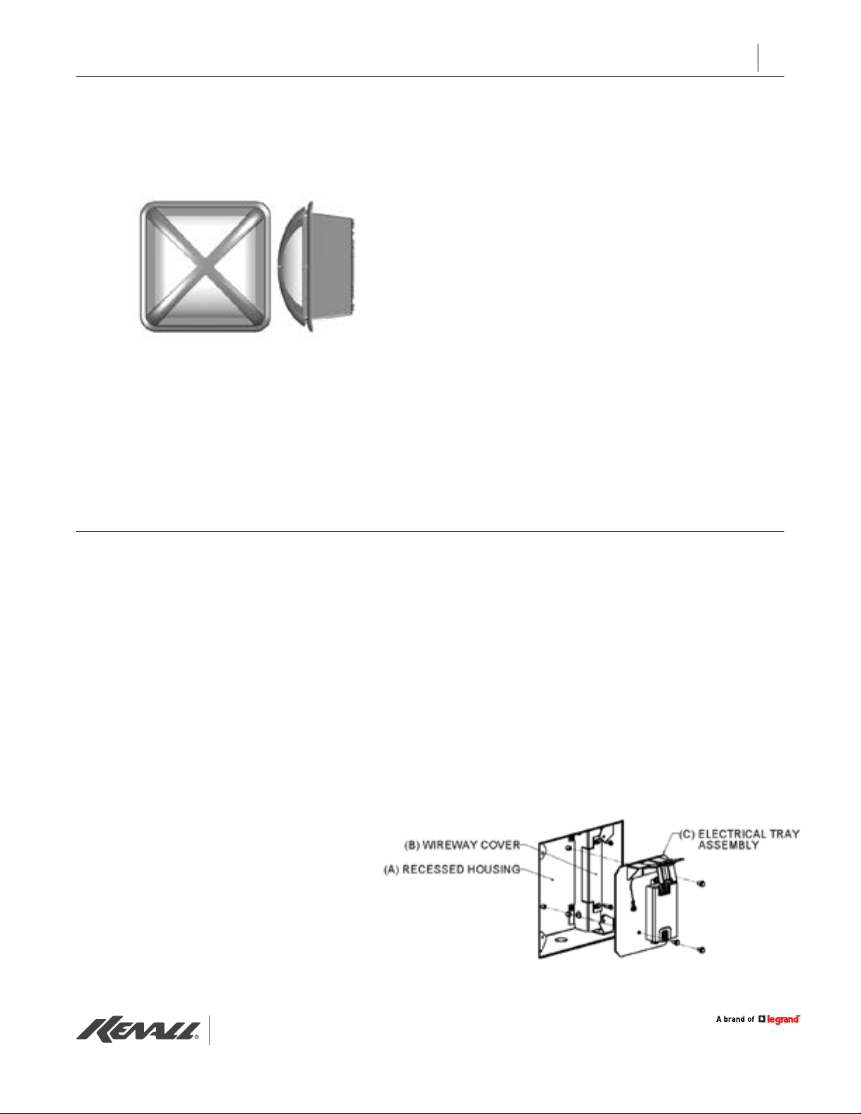
NOTE: This instruction sheet applies to wiring the
electrical tray provided for semi-recessed xtures of
type NL (non-IC low prole) and CC (Closed Canopy)
mounting styles.
1. Disconnect power to the circuit before wiring
xture(s).
2. Read all markings and labels to ensure correct
installation of xture. Additional information may
be located on the xture components, separate
from this instruction sheet, regarding orientation
and mounting restrictions.
3. Before installing electrical tray assembly, make
sure recessed housing (A) is clean, dry and free
of debris.
4. Unpack electrical tray assembly (C)
NOTE: Appearance of electrical tray will vary
depending on the model ordered.
5. Mount electrical tray assembly into recessed
housing using the three (3) supplied 10- 32 screws
(located in plastic bag). Use all screws provided.
6. Remove wireway cover (B).
7. Make electrical connections. Install in compliance
with the National Electrical Code, any applicable
local codes, and any specic instructions provided
on the luminaire labels. Supply wire must be rated
for 90°C minimum.
8. Replace wireway cover (B). Make sure all supply
wire connections are inside splice compartment.
www.kenall.com | P: 800-4-Kenall | F: 262-891-9701 | 10200 55th Street Kenosha, Wisconsin 53144, USA
This product complies with the Buy American Act: manufactured in the United Stateswith more than 50% of the component cost of US origin It may be covered by patents
found at www.kenall.com/patents. Content of specication sheets is subject to change; please consult www.kenall.com for current product details. ©2019 Kenall Mfg.Co.
MS_SR_090418
Page 2
INSTALLATION INSTRUCTIONS
2
9. Discard any screws installed in corner posts of
recessed sheet metal housing (A) (screws were
used to secure debris shield).
10. Remove lens or lens/eyelid assembly by loosening
®
the four (4) Torx
tamper-resistant screws. Screws
only need to be loosened enough to disengage
lens.
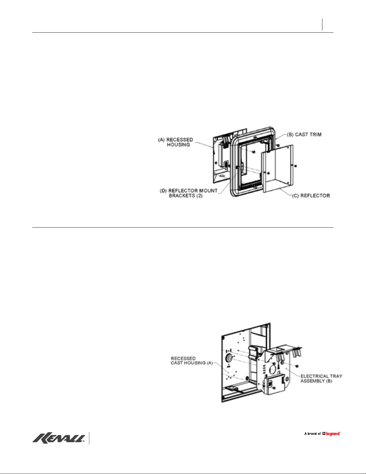
11. Prepare cast trim (B) for mounting to the recessed
sheet metal housing (A). For wet locations, caulk
backside of cast trim perimeter. This is necessary to
ensure wet location listing. Mount cast trim using
the four (4) 10-32 screws provided.
IMPORTANT: When wall mounting; attach cast trim
(B) so that reector-mount brackets (D) are aligned
to correctly position the reector (C) in relation to the
lamp socket.
12. Mount reector assembly (C). Install lamp and lens
or lens/eyelid assembly. Tighten the four (4) lens
retention screws. Check that lens or lens/eyelid is
fully secure.
PP, ND & CO INSTALLATION INSTRUCTIONS
NOTE: This instruction sheet applies to wiring the
electrical tray provided for semi-recessed xtures of
type PP (pour-in-place/masonry), ND (non-IC deep
prole) and CO (Open Canopy) mounting styles.
1. Disconnect power to the circuit before wiring
xture(s).
2. Read all markings and labels to ensure correct
installation of xture. Additional information may
be located on the xture components, separate
from this instruction sheet, regarding orientation
and mounting restrictions.
3. Before installing electrical tray assembly, make sure
recessed cast housing (A) is clean, dry and free of
debris.
4. Unpack electrical tray assembly (B)
5. Remove splice compartment cover (if supplied).
NOTE: Appearance of electrical tray will vary depending
on the model ordered.
6. Mount electrical tray assembly into recessed cast
housing using the supplied 10-32 screws (located
in plastic bag). Use all screws provided.
7. Make electrical connections. Install in compliance
with the National Electrical Code, any applicable
local codes, and any specic instructions provided
on the luminaire labels. Supply wire must be rated
for 90°C minimum.
8. If supplied, replace splice compartment cover. Make
sure all supply wire connections are inside splice
compartment.
www.kenall.com | P: 800-4-Kenall | F: 262-891-9701 | 10200 55th Street Kenosha, Wisconsin 53144, USA
This product complies with the Buy American Act: manufactured in the United Stateswith more than 50% of the component cost of US origin It may be covered by patents
found at www.kenall.com/patents. Content of specication sheets is subject to change; please consult www.kenall.com for current product details. ©2019 Kenall Mfg.Co.
MS_SR_090418
Page 3
INSTALLATION INSTRUCTIONS
3
9. Discard any screws installed in corner posts of
recessed cast housing (screws were used to
secure debris shield.
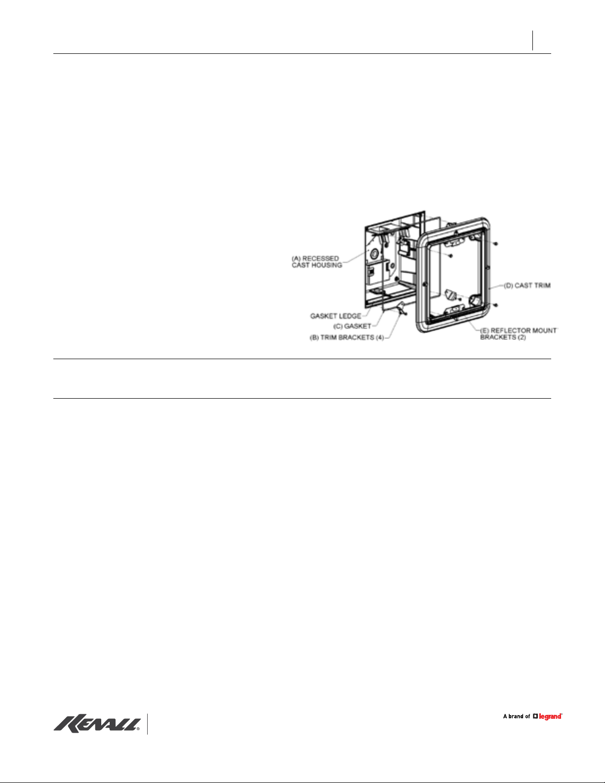
10. Attach four (4) trim brackets (B) to recessed cast
housing (A) using the 8-32 screws provided in
plastic bag.
11. Install O-ring gasket (C) into recessed cast
housing. Make sure gasket ledge is free of debris.
Stretch gasket around four corner screw posts
and seat onto gasket ledge.
12. Remove lens or lens/eyelid assembly by loosening
®
the four (4) Torx
tamper-resistant screws. Screws
only need to be loosened enough to disengage
lens.
CUSTOMER SERVICE
13. Prepare cast trim (D) for mounting to the recessed
cast housing. For wet locations, caulk backside of
cast trim perimeter. This is necessary to ensure wetlocation listing. Mount cast trim to trim brackets (B)
using the four (4) 10-32 screws provided.
IMPORTANT: When wall mounting; attach cast trim (D)
so that reector-mount brackets (E) are at 12 o’clock
and 6 o’clock positions.
14. Mount reector assembly. Install lamp and lens
or lens/eyelid assembly. Tighten the four (4) lens
retention screws.
For technical assistance, call 1-800-4KENALL (1-800-453-6255).
WARRANTY
For warranty information visit www.kenall.com/Resources/Certied-Performance-Warranties
www.kenall.com | P: 800-4-Kenall | F: 262-891-9701 | 10200 55th Street Kenosha, Wisconsin 53144, USA
This product complies with the Buy American Act: manufactured in the United Stateswith more than 50% of the component cost of US origin It may be covered by patents
found at www.kenall.com/patents. Content of specication sheets is subject to change; please consult www.kenall.com for current product details. ©2019 Kenall Mfg.Co.
MS_SR_090418
 Loading...