

Page 1

X8 MIG Welder
OPERATING MANUAL
Page 2

Contents
1 Read first......................................................................................................4
1.1 Disclaimer...........................................................................................................................................................4
1.2 Documentation symbols.............................................................................................................................. 4
1.3 Kemppi symbols.............................................................................................................................................. 4
2 X8 MIG Welder............................................................................................8
2.1 Disclaimer...........................................................................................................................................................8
2.2 System introduction.......................................................................................................................................8
2.2.1 Introduction to WeldEye for welding procedure and qualification
management........................................................................................................................................10
2.3 System structure........................................................................................................................................... 10
2.3.1 X8 Power Source..........................................................................................................................11
2.3.2 X8 Wire Feeder............................................................................................................................. 15
2.3.3 X8 MIG Guns..................................................................................................................................21
2.3.4 Control Pad.....................................................................................................................................23
2.4 Installation....................................................................................................................................................... 26
2.4.1 Before installation........................................................................................................................ 26
2.4.2 Power Source installation......................................................................................................... 27
2.4.3 Wire Feeder installation.............................................................................................................35
2.4.4 Cables installation........................................................................................................................51
2.4.5 Control Pad installation............................................................................................................. 55
2.4.6 Welding gun installation........................................................................................................... 60
2.4.7 Lifting X8 MIG Welder............................................................................................................... 89
2.4.8 Purchasing and managing welding software....................................................................90
2.4.9 Optional accessories...................................................................................................................90
2.5 Operation.........................................................................................................................................................93
2.5.1 X8 MIG Welder control devices............................................................................................. 93
2.5.2 Preparing welding system for use...................................................................................... 108
2.5.3 How to use welding system..................................................................................................117
2.6 Troubleshooting..........................................................................................................................................156
2.6.1 Error codes................................................................................................................................... 159
2.7 Maintenance.................................................................................................................................................159
2.7.1 Daily maintenance.....................................................................................................................159
2.7.2 Periodic maintenance of power source and wire feeder........................................... 161
2.7.3 Service workshops.....................................................................................................................162
2.8 Technical data..............................................................................................................................................162
2.8.1 X8 Power Source 400 A.......................................................................................................... 162
2.8.2 X8 Power Source 500 A / 500 A MV................................................................................. 164
2.8.3 X8 Cooler...................................................................................................................................... 166
2.8.4 X8 Wire Feeder...........................................................................................................................167
2.8.5 X8 Control Pad........................................................................................................................... 168
2.8.6 X8 MIG Gun 200-g................................................................................................................... 169
2.8.7 X8 MIG Gun 300-g................................................................................................................... 170
2.8.8 X8 MIG Gun 400-g................................................................................................................... 171
ii
Page 3

2.8.9 X8 MIG Gun 400-w...................................................................................................................172
2.8.10 X8 MIG Gun 500-w................................................................................................................ 174
2.9 Ordering codes...........................................................................................................................................175
2.10 Disposal of unit........................................................................................................................................178
iii
Page 4

X8 MIG WELDER 1.1 Disclaimer
1 Read first
Kemppi takes special care in informing its customers about the safety of our products. We also
mind the environment and aspire to disposing of our products according to specified European
Directives.
1.1 Disclaimer
While every effort has been made to ensure that the information contained in this guide is
accurate and complete, no liability can be accepted for any errors or omissions. Kemppi reserves
the right to change the specification of the product described at any time without prior notice. Do
not copy, record, reproduce or transmit the contents of this guide without prior permission from
Kemppi.
1.2 Documentation symbols
Items in the manual that require particular attention, to minimize damage and personal harm, are
indicated with a three-level notification and warning system.
Convention Used for
Note:
Note text here.
Caution:
Caution text here.
Warning:
Warning text here.
Gives the user a piece of information of particular importance.
Describes a situation that may result in damage to the
equipment or system.
Describes a potentially dangerous situation that may result in
personal damage or fatal injury.
1.3 Kemppi symbols
Table 1: Kemppi symbols used in this documentation
Symbol Description
CE mark
OPERATING MANUAL | EN 4
©
KEMPPI 2017 | 1817
Page 5

X8 MIG WELDER 1.3 Kemppi symbols
Symbol Description
EMC Class A
This symbol indicates that the waste of electrical and electronic
equipment must not be disposed as unsorted municipal waste
and must be collected separately. Contact an authorized
representative of the manufacturer for information concerning the
decommissioning of your equipment.
Coolant input
Coolant output
#
Gas input
Gas output
High voltage
Protective earth
1-MIG
Double Pulse MIG
'
OPERATING MANUAL | EN 5
©
KEMPPI 2017 | 1817
Page 6

X8 MIG WELDER 1.3 Kemppi symbols
Symbol Description
Carbon arc gouging
8
MIG
!
MMA
5
Pulse MIG
%
,
*
+
WiseRoot
WiseThin
WiseFusion
WiseSteel
WisePenetration+
Creep Start
P
OPERATING MANUAL | EN 6
©
KEMPPI 2017 | 1817
Page 7

X8 MIG WELDER 1.3 Kemppi symbols
Symbol Description
Hot Start
S
Upslope
R
Crater Fill with Downslope
T
Crater Fill with Downlevel
U
Ö
Õ
O
2T
4T
User manual
OPERATING MANUAL | EN 7
©
KEMPPI 2017 | 1817
Page 8
X8 MIG WELDER 2.1 Disclaimer
2 X8 MIG Welder
These instructions describe the use of Kemppi's X8 MIG Welder, the top-class welding system
for demanding industrial use. The system consists of a power source, wire feeder, welding gun,
Control Pad and various welding software components and connectivity to Kemppi cloud services.
Read the instructions through carefully.
2.1 Disclaimer
While every effort has been made to ensure that the information contained in this guide is
accurate and complete, no liability can be accepted for any errors or omissions. Kemppi reserves
the right to change the specification of the product described at any time without prior notice. Do
not copy, record, reproduce or transmit the contents of this guide without prior permission from
Kemppi.
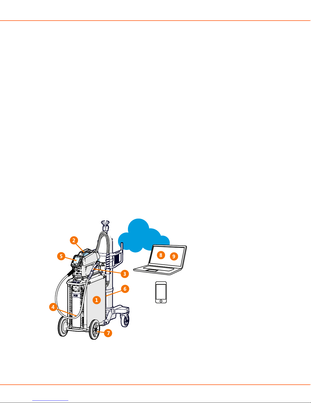
2.2 System introduction
X8 MIG Welder is a multi-process welding equipment intended for demanding professional use in
general or heavy fabrication. The welding system is suitable for various MIG/MAG processes (MIG,
1-MIG, Pulse, DPulse, WiseRoot+, WiseThin+ ) as well as MMA welding and gouging, cladding
and brazing.
1. X8 Power Source 400/500/600
• Includes all the software, welding programs and memory channels for the welding system
OPERATING MANUAL | EN 8
©
KEMPPI 2017 | 1817
Page 9

X8 MIG WELDER 2.2 System introduction
• Connects to one or two X8 Wire Feeders
2. X8 Wire Feeder
• Operates with several wire spool types (some of which require an adapter)
• Connects to an external wire drum
• Contains a control panel for basic adjustment of welding parameters, memory channels
and settings
3. X8 MIG Gun 200/300/400-g, 400/500
• Connects to the wire feeder with Kemppi Gun Adapter
• Gas-cooled models feature a rotating, changeable neck
• Remote control for selecting memory channels and adjusting settings (optional)
• Ergonomic pistol grip handle
4. X8 Cooler (optional)
• Optionally included in the power source delivery
• Can also be purchased separately
• Essential for welding with a current over 400 A
5. Control Pad
• Wireless remote interface for operating X8 MIG Welder
6. Interconnection Cable 70/95-w/-g (several options)
• Bundle of cables connecting the wire feeder to the power source
• Transfers the welding current, control signals, shielding gas and coolant from the power
source to the wire feeder
7. X8 Wheel Set (several options)
• The wheel set is included in the power source delivery
• The gas cylinder cart is optionally included in the power source delivery
8. My Fleet web service
• Cloud-based service for viewing and managing various information about your X8 MIG
Welder
• Provides manufacturer's validation certificate
9. WeldEye (optional)
• Cloud-based service for creating and managing digital WPS documents and other weldingrelated information
In addition:
• Several accessories (optional)
• Several welding software products (optional)
OPERATING MANUAL | EN 9
©
KEMPPI 2017 | 1817
Page 10

X8 MIG WELDER 2.3 System structure
2.2.1 Introduction to WeldEye for welding procedure and
qualification management
Welding procedure and qualification management
WeldEye for Welding procedure and qualification management is a cloud-based tool for creating,
managing and storing various welding-related documents and qualification certificates. WeldEye
is an end-to-end solution for handling pWPS, WPQR and WPS documents as well as welder
qualification certificates. The software contains procedure and certificate templates to match all
major welding standards. Together with its integrated drawing tool, WeldEye is swift and easy to
use.
The software enables you to keep track of qualification certificates and their expiration dates,
and to easily extend their validity. Revision history helps you track the changes made to the
documents. With a flexible search functionality, you can easily find the welding procedures,
personnel, and certificates you need. You can print out documents or, for example, a list of
welders with a certain qualification certificate. Attachments can be added to any document.
Discover WeldEye – universal welding management software
WeldEye is your primary tool and storage space for keeping your welding-related documents in
order.
There is even more to WeldEye than welding document management. WeldEye is a universal
solution for managing welding production. Fitting any size and type of organization that performs
welding within the requirements of international welding standards like ISO, ASME and AWS,
WeldEye provides control in all processes - including welding procedures, welder and inspector
qualifications, documentation, reporting and administration. Most importantly, you get 100%
traceability for every weld you ever make.
WeldEye's modular structure is based on various useful functions that serve the needs of wideranging industries and welding-related tasks:
Welding procedures
Includes the digital library and management of pWPS, WPQR and WPS templates according to
the most important welding standards.
Personnel and qualifications
Includes the management and renewal processes of all personnel - welders and inspectors qualification certificates.
Quality management
Includes quality verification functionalities with digital WPS and qualification compliance
control against automatically collected digital welding data.
Welding management
Includes document register functionalities and features for comprehensive welding project
documentation and management.
For more information on the full system and other modules, see www.weldeye.com.
2.3 System structure
OPERATING MANUAL | EN 10
©
KEMPPI 2017 | 1817
Page 11
X8 MIG WELDER 2.3 System structure
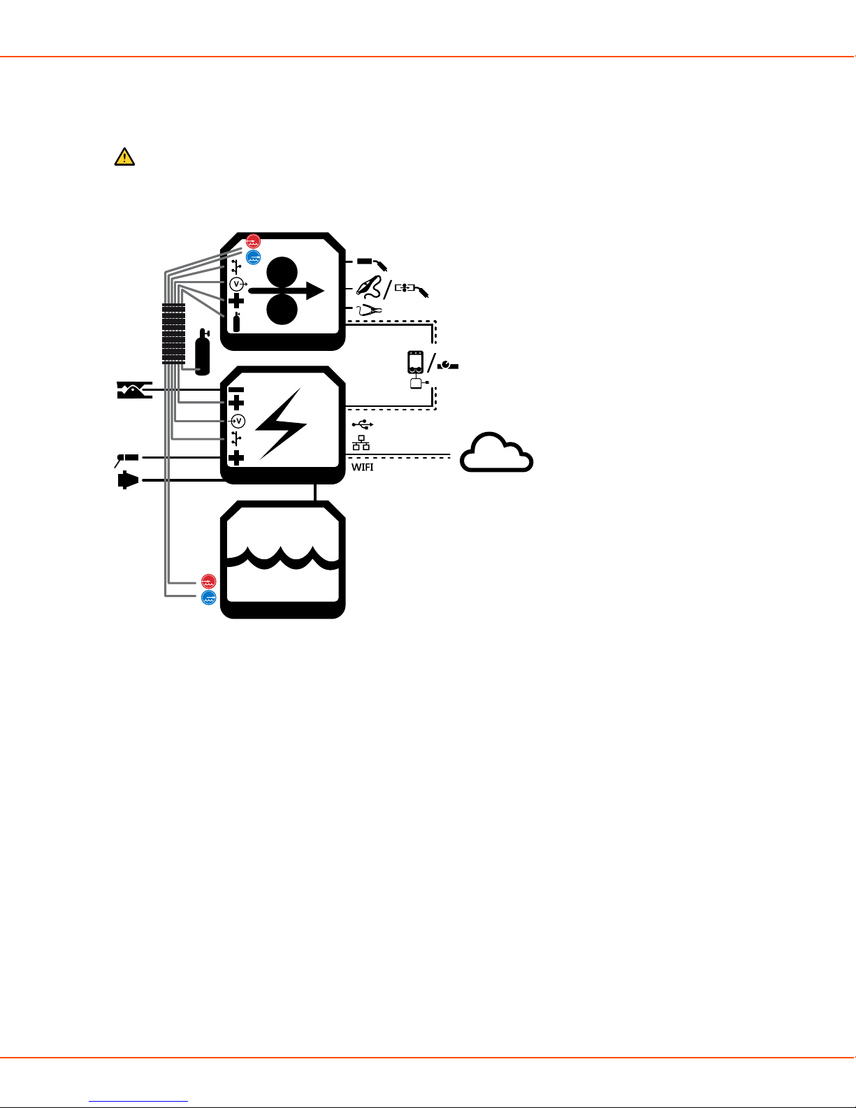
The parts of X8 MIG Welder are in close co-operation with each other. The information transfer is
efficient and quick, and the different functions, for example, the use of displays, follow the same
principles.
Caution:
Do not modify the welding equipment in any way, except for the changes and
adjustments covered in the manufacturer’s instructions.
Figure 1: A chart of the connections between the different parts of X8 MIG Welder
2.3.1 X8 Power Source
This section describes the X8 Power Source structure.
OPERATING MANUAL | EN 11
©
KEMPPI 2017 | 1817
Page 12

X8 MIG WELDER 2.3 System structure
Front
1
6
7
5
42 3
1. Indicator panel
2. Transportation handle
3. USB connector
Connect a USB memory stick to upload the welding procedures (WPS) or Wise features to the
power source or update firmware if a wireless connection is unavailable.
4. Control Pad connector
Connect Control Pad to the power source with a cable to charge its battery or to use it in
wired mode.
5. Front panel
6. Front panel latch
Pull to open the front panel and reveal the coolant container.
7. Coolant circulation button
Press to pump the coolant through the system.
OPERATING MANUAL | EN 12
©
KEMPPI 2017 | 1817
Page 13

X8 MIG WELDER 2.3 System structure
Rear
1
12
3
3
2
2
4
5
6
8
9
4
5
7
10
11
1. Transportation handle
2. Welding current cable connectors (positive pole)
3. Earth return cable connectors (negative pole)
4. Measurement cable connectors
Connectors for wire feeder 1 on the left, wire feeder 2 on the right side of the power source.
5. Control cable connectors
Connectors for wire feeder 1 on the left, wire feeder 2 on the right side of the power source.
6. Ethernet connector
7. Power switch
8. Coolant outlet hose connector
9. Coolant inlet hose connector
10. Rear panel
11. Mains cable
12. Strain relief holder
OPERATING MANUAL | EN 13
©
KEMPPI 2017 | 1817
Page 14

X8 MIG WELDER 2.3 System structure
Indicator panel
1. Power indicator
The LED is green when the unit is on.
2. Voltage Reduction Device (VRD) indicator
The LED is green when VRD is working normally.
The LED is red when the no load voltage is above 35 V.
3. Overheat indicator
The LED is yellow when the unit is overheating.
Caution:
If the power source overheats, a thermal cutoff switches the unit off and does not
allow it to be used until it has cooled down.
4. Kemppi cloud connection
The LED is blue when the wire feeder or power source is connected to Kemppi cloud services.
The LED is blinking blue when the wire feeder or power source is connecting to Kemppi cloud
services.
5. Coolant level warning
The LED is yellow when the coolant level is too low.
6. Coolant temperature warning
The LED is yellow when the cooler is overheating.
Caution:
If the coolant liquid overheats, a thermal cutoff switches the welding system off and
does not allow it to be used until the coolant liquid has cooled down.
7. Coolant circulation warning
The LED is green when the coolant circulation is working normally.
The LED is red when there is a problem in the coolant circulation.
The LED blinks green and red in turns when the circulation of the coolant liquid has been
obstructed too long.
OPERATING MANUAL | EN 14
©
KEMPPI 2017 | 1817
Page 15
X8 MIG WELDER 2.3 System structure
Caution:
If the circulation of the coolant liquid is obstructed, a thermal cutoff switches the
welding system off. Check and fix the error before using the welding system again.
If the error was caused in an unsuccessful filling of the cooler, refill the cooler. In
other cases, the error disappears automatically in 30 seconds.
8. Wireless pairing button
To pair the wire feeder or power source with Control Pad, press the button. If the power source
is connected to wire feeder(s), the wire feeder(s) pairs with Control Pad. If the power source is
not connected to a wire feeder, the power source pairs with Control Pad.
The LED is blue when the wire feeder or power source is wirelessly connected to Control Pad.
The LED is blinking blue when the wire feeder or power source is pairing with Control Pad.
Interconnection cable
4
3
2
1
1. Shielding gas hose
2. Coolant inlet hose
3. Coolant outlet hose
4. Welding current cable
7
65
5. Control cable
6. Measurement cable
7. Strain relief pin
2.3.2 X8 Wire Feeder
This section describes the X8 Wire Feeder structure.
OPERATING MANUAL | EN 15
©
KEMPPI 2017 | 1817
Page 16

X8 MIG WELDER 2.3 System structure
Main parts
1. Top cover
Caution:
Keep the wire feeder top cover closed during welding to reduce the risk of injury
or an electric shock. Keep the top cover closed also at other times to keep the wire
feeder insides clean.
2. Handle
Caution:
The handle is only intended for short distance manual carrying. Use Wire Feeder
Hanger for Boom for lifting or hanging the wire feeder.
3. Top cover latch
4. Cable cabinet door
5. Cable cabinet latch
6. Control panel
7. Strain relief
8. Strain relief latch
9. Gun holder mount
OPERATING MANUAL | EN 16
©
KEMPPI 2017 | 1817
Page 17

X8 MIG WELDER 2.3 System structure
1011
13
15
12
14
Figure 2: The warning sticker inside the wire feeder
10. Wire spool
11. Wire spool locking cover
12. Feed rolls
13. Pressure handle
14. Wire guide
15. Inside control buttons
OPERATING MANUAL | EN 17
©
KEMPPI 2017 | 1817
Page 18

X8 MIG WELDER 2.3 System structure
Control panel
The control panel on the front of the wire feeder enables easy control of the wire feeder's basic
features. Although Control Pad is the main control of the welding system, you can also use the
wire feeder control panel or the welding gun remote control.
2
2
4
4
1
1
6
6
3
3
5
5
The wire feeder control panel parts are:
1. Locking button
Press and hold for 2 seconds to lock or release the display and buttons.
2. Channel button
The button lights up blue, when the view is activated.
OPERATING MANUAL | EN 18
©
KEMPPI 2017 | 1817
Page 19
X8 MIG WELDER 2.3 System structure
3. Settings button
The button lights up orange, when the view is activated.
4. Left control knob
5. Right control knob
6. Left and right button
For more information on the use and features of the control panel, see Wire feeder views on page
106.
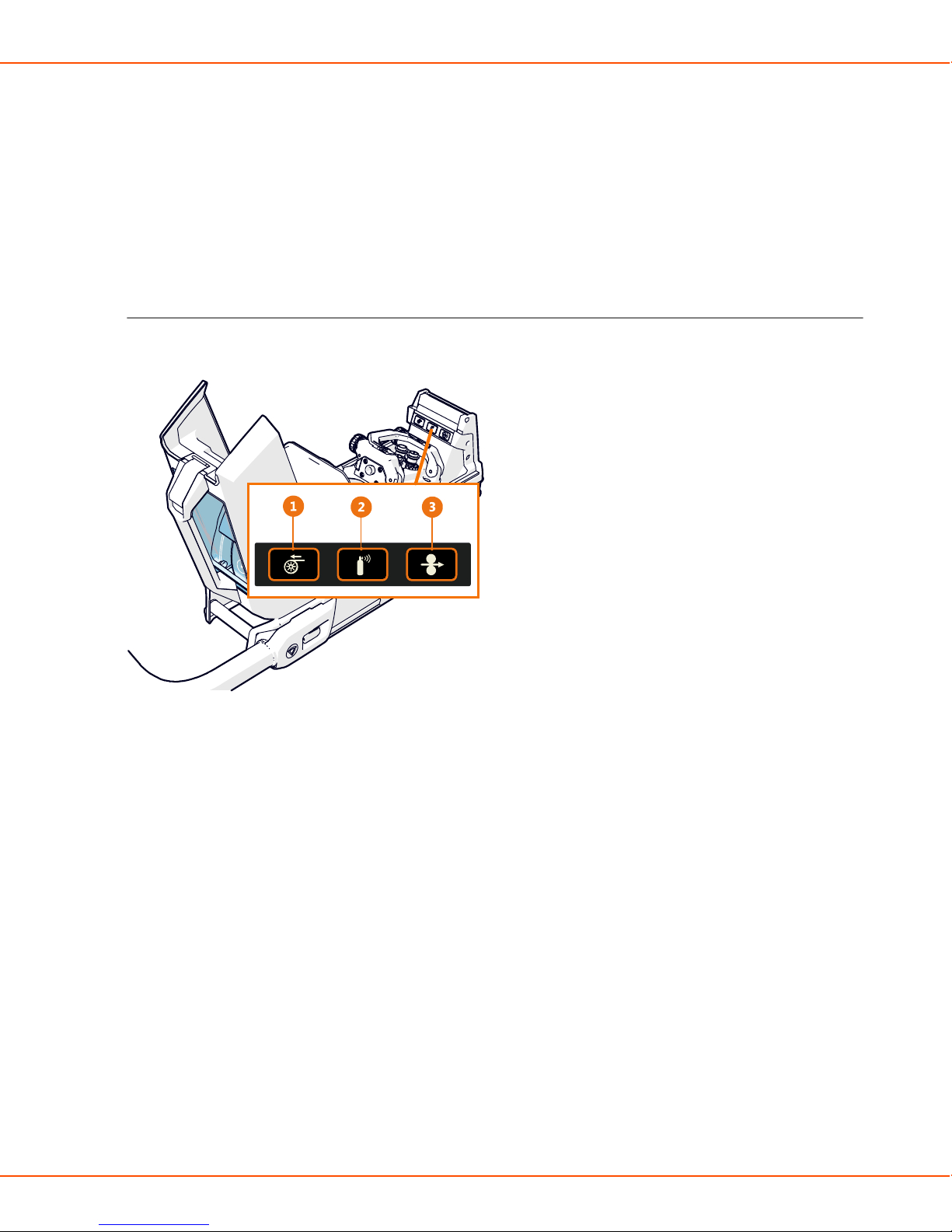
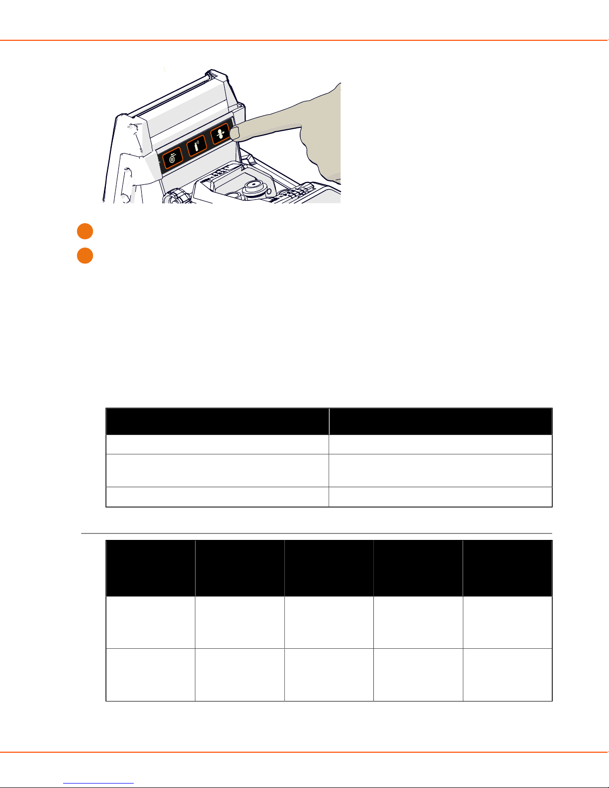
Control buttons on the inside
The wire feeder has control buttons inside the wire cabinet.
1. Wire retract button
Drive the filler wire backward with arc off.
2. Gas test button
Test the shielding gas flow, or flush out the remainder of the previous gas.
3. Wire inch button
Drive the filler wire forward with arc off.
OPERATING MANUAL | EN 19
©
KEMPPI 2017 | 1817
Page 20

X8 MIG WELDER 2.3 System structure
Interconnection cable connectors
1. Welding current
Supplies current from the power source to the wire feeder.
2. Shielding gas
Supplies shielding gas to the welding gun.
3. Measurement
Supplies the welding parameters measured during welding.
4. Control
Supplies data and operating voltage to the wire feeder.
5. Coolant outlet and inlet
Circulates coolant to and from the welding gun.
For information on the installation of the cables, see Cables installation on page 51.
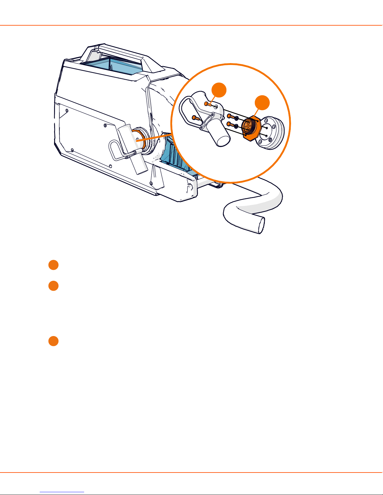
External component connectors
1. Kemppi Gun Adapter
Connects to the welding gun.
Note:
The wire feeder is supplied with Kemppi Gun Adapter.
2. Subfeeder
Provides control to optional SuperSnake subfeeder or a motorized welding gun.
OPERATING MANUAL | EN 20
©
KEMPPI 2017 | 1817
Page 21

X8 MIG WELDER 2.3 System structure
3. Remote control
Connects to remote control devices (Control Pad). Supplies power and data connection with
12 V voltage.
4. Voltage sensing
Connects to the welding piece and measures arc voltage in real time.
5. Coolant outlet
Delivers cold coolant to the welding gun.
6. Coolant inlet
Receives heated coolant from the welding gun.
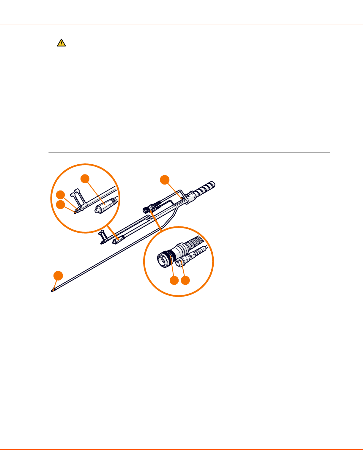
2.3.3 X8 MIG Guns
This section describes the structure of X8 MIG guns.
Gas-cooled gun
754 6 8
3
2
1
1. Gas nozzle
2. Contact tip
9
10
11
3. Contact tip adapter
4. Neck
5. Neck tightener
OPERATING MANUAL | EN 21
©
KEMPPI 2017 | 1817
Page 22

X8 MIG WELDER 2.3 System structure
6. Work light
Press the trigger lightly to switch on the light.
7. Place for X8 Gun Remote Control
The remote control will become available in a later release.
8. Trigger
9. Trigger on the pistol grip handle
10. Pistol grip handle
Quick to attach and detach.
11. Kemppi Gun Connector
Water-cooled gun
1. Gas nozzle
2. Insulating bush
3. Contact tip
4. Contact tip adapter
5. Gas diffuser
6. Neck
OPERATING MANUAL | EN 22
©
KEMPPI 2017 | 1817
Page 23
X8 MIG WELDER 2.3 System structure
7. Work light
Press the trigger lightly to switch on the light.
8. Place for X8 Gun Remote Control
The remote control will become available in a later release.
9. Trigger
10. Trigger on the pistol grip handle
11. Pistol grip handle
Quick to attach and detach.
12. Kemppi Gun Connector
13. Coolant inlet hose
14. Coolant outlet hose
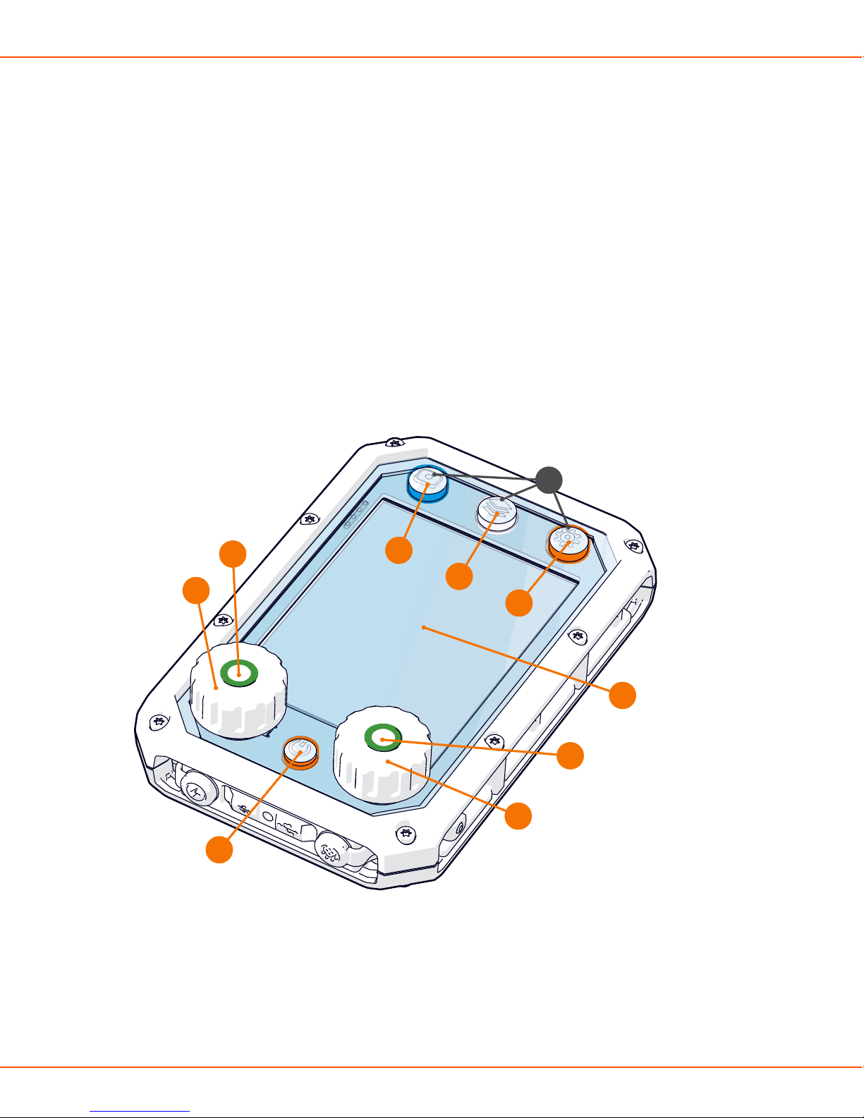
2.3.4 Control Pad
This section describes the Control Pad structure.
6
6
7
4
4
2
2
1
1
7
8
8
9
9
5
5
4
4
3
3
1. Power button
The button lights up orange, when you switch Control Pad on.
2. Left control knob
3. Right control knob
OPERATING MANUAL | EN 23
©
KEMPPI 2017 | 1817
Page 24

X8 MIG WELDER 2.3 System structure
4. Left and right button
When the button lights up green, you can press the button to confirm an action.
5. Display
6. View buttons
7. Channel button
The button lights up blue, when the view is activated.
8. Menu button
The button lights up white, when the view is activated.
9. Settings button
The button lights up orange, when the view is activated.
10. NFC reader
13
12
11
10
14
11. Bar code reader
12. ON/OFF button for NFC and bar code readers
13. Loop for a sling
14. Hook
When you connect or disconnect the charger, Control Pad shows you the charge level.
OPERATING MANUAL | EN 24
©
KEMPPI 2017 | 1817
Page 25

X8 MIG WELDER 2.3 System structure
When Control Pad is charging, green leds on the left side of the display indicate ongoing
charging. The lowest led turns red when the charge level is low.
OPERATING MANUAL | EN 25
©
KEMPPI 2017 | 1817
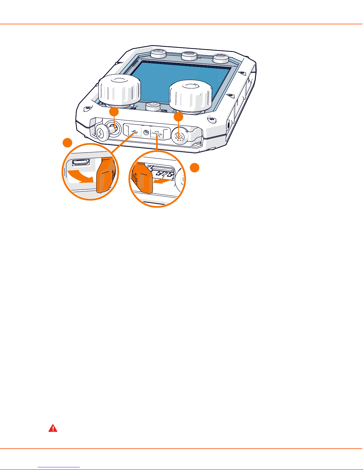
Page 26
X8 MIG WELDER 2.4 Installation
15
16
18
17
15. Charger cable port
A stopper shields the charger cable port.
16. Micro USB port
A cover shields the micro USB port and the USB cable port.
17. USB cable port
18. Combo cable port
Combo cable port transfers both data and power. A stopper shields the combo cable port.
2.4 Installation
Perform this installation procedure to prepare your X8 MIG Welder for use.
Read the instructions carefully and follow them closely.
2.4.1 Before installation
Make sure to acknowledge and follow the local and national requirements on installation and the
use of high voltage units.
Before installation, check the contents of the packages and make sure the parts are not damaged.
Before you remove the power source completely from its packaging, install the wheel set.
Before you install the power source on the site, see the following requirements regarding the
mains cable type and fuse rating.
Warning:
OPERATING MANUAL | EN 26
©
KEMPPI 2017 | 1817
Page 27

X8 MIG WELDER 2.4 Installation
The mains cable must be installed by an authorized electrician.
Warning:
Provided that the public low voltage short circuit power at the point of common coupling
is higher than or equal to 5.1 MVA, this equipment is compliant with IEC 61000-3-11
and IEC 61000-3-12 and can be connected to public low voltage systems. It is the
responsibility of the installer or user of the equipment to ensure, by consultation with the
distribution network operator if necessary, that the system impedance complies with the
impedance restrictions.
Table 2: Cable type and fuse rating requirements
Unit amperage
High voltage version (380-460 V) Multi-voltage version
(220-230 /380-460V)
Cable type Fuse rating Cable type Fuse rating
400 A 6 mm
500 A 6 mm
600 A 6 mm
2
2
2
25 A - -
32 A 16 mm
35 A 16 mm
2
2
63 A
63 A
2.4.2 Power Source installation
For power source cable connections, see Installing interconnection cable and Installing or
replacing mains cable. For operating the power source, see Preparing welding system for use.
2.4.2.1 Installing wheels
To have turning wheels in the front and the back, install the front wheel assembly to the front of
the unit. To have fixed wheels in the front, install the rear wheel assembly to the front of the unit.
See also .
Proceed as follows:
Install the rear wheels.
1.
a) Remove the packaging from the sides but leave the power source resting on the pallet.
OPERATING MANUAL | EN 27
©
KEMPPI 2017 | 1817
Page 28

X8 MIG WELDER 2.4 Installation
b) Push the rear axle through the opening in the bottom of the rear side of the unit and set
the axle in the middle.
c) Slide the two wheel spacers (1) onto the axle.
d) Slide the two wheels (2) onto the axle.
e) Slide the two washers (3) onto the axle.
f) Slide the two retaining rings (4) on the axle, until they lock into the groove on the axle.
OPERATING MANUAL | EN 28
©
KEMPPI 2017 | 1817
Page 29
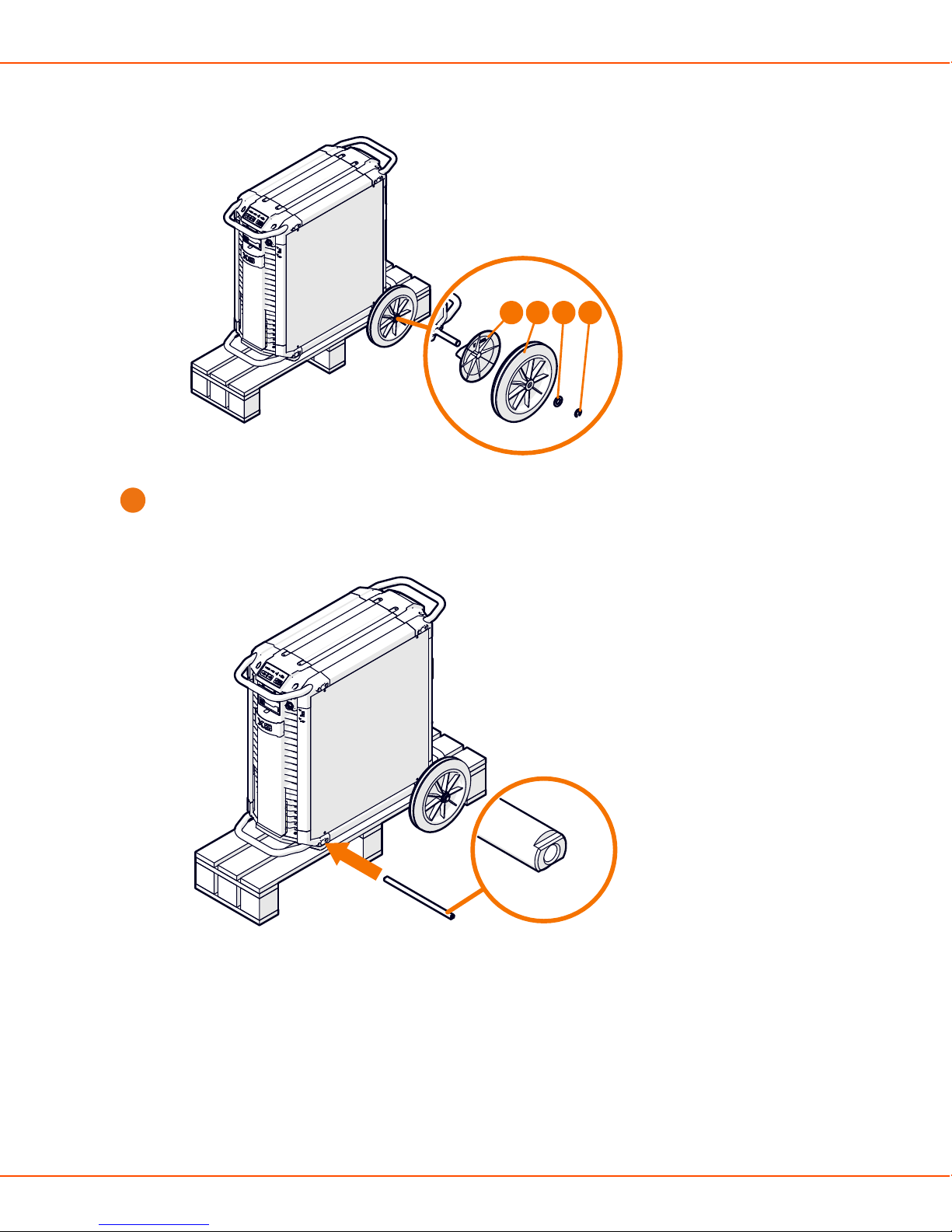
X8 MIG WELDER 2.4 Installation
1 2 3 4
Install the front wheels.
2.
a) Push the front axle through the opening in the bottom of the front side of the unit and set
the axle in the middle.
b) Place the transportation handle over the ridge in the wheel assembly and align the holes
in the wheel assembly with the ends of the axle.
c) Attach the front wheel assembly to the end of the axle with a bolt (1) and washer (2) from
both sides.
OPERATING MANUAL | EN 29
©
KEMPPI 2017 | 1817
Page 30
X8 MIG WELDER 2.4 Installation
Max. 20 Nm
21
d) When the wheels are attached, lift the power source off the pallet.
Note:
If your setup includes X8 Gas Cylinder Cart, proceed to Installing optional gas cylinder
cart.
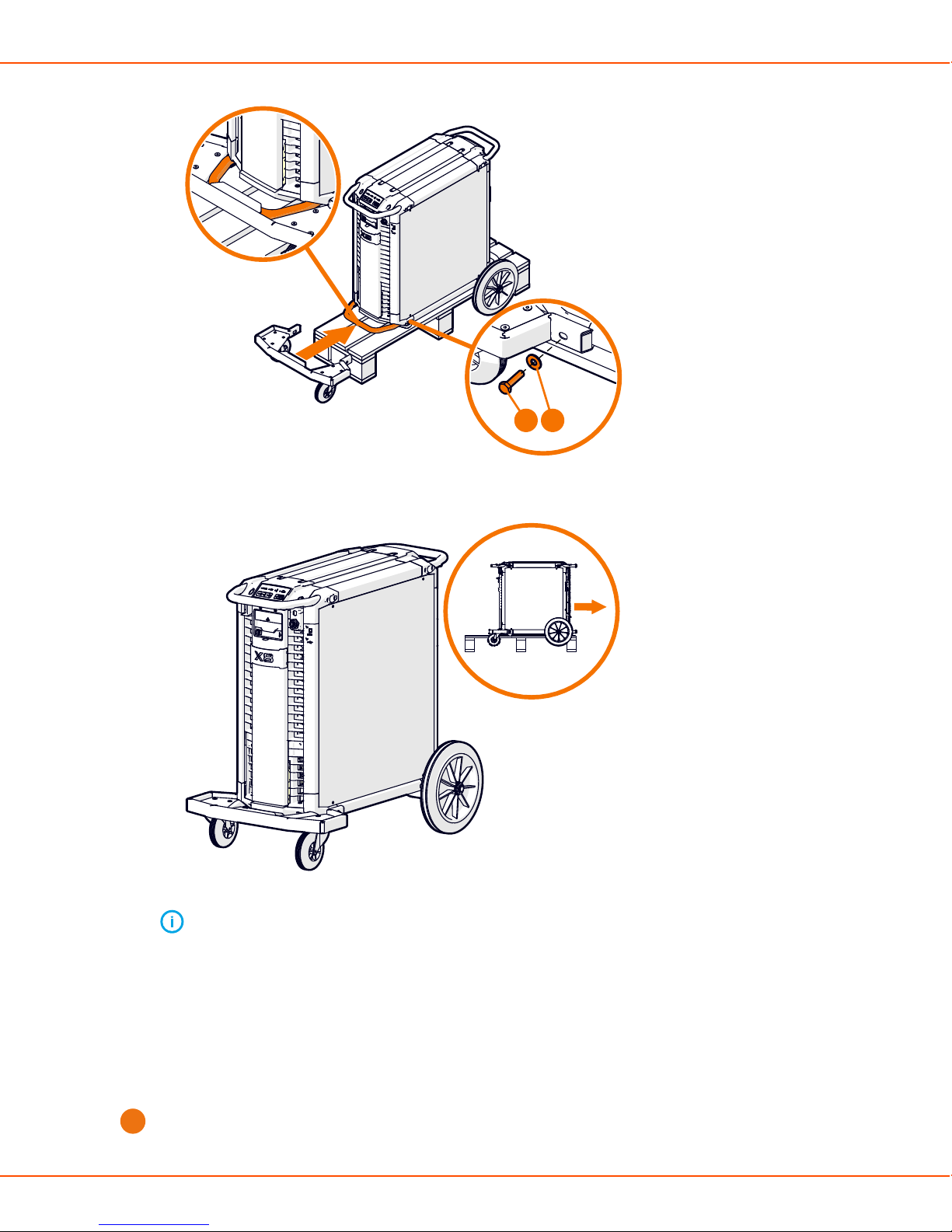
2.4.2.2 Installing optional gas cylinder cart
To transport a larger gas cylinder with the power source, install X8 Gas Cylinder Cart. For detailed
instructions, see X8 Gas Cylinder Cart Mounting Instructions. If your setup does not include the
gas cylinder cart, proceed to Installing optional X8 Cooler.
Remove the packaging from the sides but leave the power source resting on the pallet.
1.
OPERATING MANUAL | EN 30
©
KEMPPI 2017 | 1817
Page 31
X8 MIG WELDER 2.4 Installation
Attach a wheel set to the front of the unit.
2.
• To have turning wheels in the front and the back, install the front wheel assembly to the
front of the unit.
For more information, see Installing wheels on page 27.
• To have fixed wheels in the front, install the rear wheel assembly to the front of the unit.
For more information, see Installing wheels on page 27.
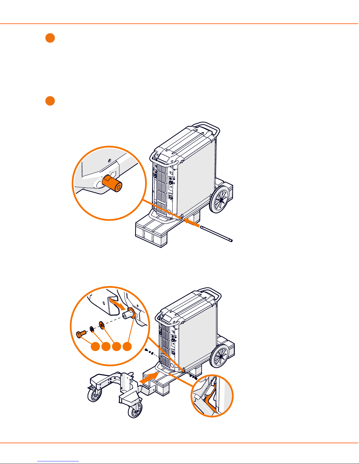
Attach the gas cylinder cart to the rear of the unit.
3.
a) Push the axle through the opening in the bottom of the rear side of the unit.
b) Attach the wheel set of the gas cylinder cart to the axle with a bolt (1) and washers (2, 3, 4)
from both sides.
4321
OPERATING MANUAL | EN 31
©
KEMPPI 2017 | 1817
Page 32

X8 MIG WELDER 2.4 Installation
c) Insert cover plugs to the open ends of the wheel set.
d) Place the upper part of the gas cylinder cart on the wheel set, and push it down until the
claw fastens over the transportation handle.
3 2 1
e) Attach the upper part of the gas cylinder cart to the wheel set with two bolts (1) and
washers (2, 3) from both sides.
f) Attach the bottom of the gas cylinder cart to the wheel set with six bolts (1) and washers
(2, 3).
The gas cylinder cart bottom has two alternative settings (the lower setting described in
the figure). The higher setting gives a better ground clearance, but you must lift the gas
cylinder higher.
OPERATING MANUAL | EN 32
©
KEMPPI 2017 | 1817
Page 33

X8 MIG WELDER 2.4 Installation
Max. 20 Nm
3 2 1
g) Place the gas cylinder on the cart.
h) Fasten the straps in the cart around the gas cylinder.
2.4.2.3 Installing optional X8 Cooler
If your setup does not include X8 Cooler, you can skip these instructions.
Caution:
X8 Cooler must be installed by authorized service personnel. Do not open the covers of
X8 Power Source.
OPERATING MANUAL | EN 33
©
KEMPPI 2017 | 1817
Page 34

X8 MIG WELDER 2.4 Installation
2
3
1
64 5
1. Front panel
2. Front panel latch
3. Coolant circulation button
4. Cooler
5. Coolant container
6. Connectors for the liquid cooling unit
Proceed as follows:
Detach the two screws in the front panel of the power source.
1.
OPERATING MANUAL | EN 34
©
KEMPPI 2017 | 1817
Page 35

X8 MIG WELDER 2.4 Installation
Pull the front panel outwards from the lower edge.
2.
Remove the lower left cover from the rear of the power source.
3.
Push the cooler inside the power source from the opening in the front.
4.
Note:
Do not use force, but make sure the connectors on the cooler and the power source
are properly connected.
Fill the coolant container with applicable coolant solution. For more information, see Filling
5.
cooler on page 111.
Attach the two screws in the front panel of the power source.
6.
2.4.2.4 Installing or replacing mains cable
The power source is supplied with a 5-meter mains cable without a plug installed.
Warning:
The mains cable must be installed by an authorized electrician.
For high voltage versions, install the 6 mm2 cable. For multi-voltage versions, install the 16 mm
cable.
2
The mains cable includes the following wires:
1. Brown: L1
2. Black: L2
3. Grey: L3
4. Yellow-green: Protective earth
2.4.3 Wire Feeder installation
This chapter describes the wire feeder installation.
For wire feeder cable connections, see Installing interconnection cable. For information on
operating the wire feeder, see Wire feeder control panel on page 106.
2.4.3.1 Installing wire feeder
The installation of the Wire Feeder Rotating Plate and Double Wire Feeder Rotating Plate is
identical, as is installing one or two wire feeders.
Install the wire feeder on the power source with a Wire Feeder Rotating Plate. To install two wire
feeders, use a Double Wire Feeder Rotating Plate.
Proceed as follows:
Place the wire feeder rotating plate or double rotating plate on top of the power source, with
1.
the orange claw at the rear of the unit.
OPERATING MANUAL | EN 35
©
KEMPPI 2017 | 1817
Page 36

X8 MIG WELDER 2.4 Installation
Pull the release lever at the front of the wire feeder rotating plate, and turn the top sideways
2.
to allow access to the bottom half.
Attach the bottom of the wire feeder rotating plate to the power source with four screws (1)
3.
and washers (2).
OPERATING MANUAL | EN 36
©
KEMPPI 2017 | 1817
Page 37

X8 MIG WELDER 2.4 Installation
5 Nm
1
2
With the control panel facing the same way as the power source front panel, place the wire
4.
feeder in the corresponding grooves on the wire feeder rotating plate.
Slide the wire feeder from front to back until the bar in the back of the unit locks to the
5.
orange claw at the back of the wire feeder rotating plate.
2.4.3.2 Installing welding gun holder
Install the welding gun holder to either side of the wire feeder.
OPERATING MANUAL | EN 37
©
KEMPPI 2017 | 1817
Page 38
X8 MIG WELDER 2.4 Installation
2
121
Proceed as follows:
Install the welding gun holder mount to the wire feeder with 2 screws going to the
1.
corresponding holes on the wire feeder upper cover hinge.
Attach the welding gun holder to the mount with 2 screws.
2.
2.4.3.3 Replacing feed rolls
Replace the feed rolls when the material and diameter of the filler wire changes.
Proceed as follows:
Open the top cover and lift the pressure handle.
1.
OPERATING MANUAL | EN 38
©
KEMPPI 2017 | 1817
Page 39

X8 MIG WELDER 2.4 Installation
Push the collars on the mounting pins of the feed rolls up to pull the mounting pins off.
2.
OPERATING MANUAL | EN 39
©
KEMPPI 2017 | 1817
Page 40

X8 MIG WELDER 2.4 Installation
Note:
The mounting pins are different: The drive rolls' mounting pins have a circular mark
on the top, while the pressure rolls' mounting pins have no marks. The pressure rolls'
mounting pins have central axles attached to them, so the drive and pressure rolls'
mounting pins cannot be confused with each other.
Pull the drive rolls upwards (1) and the pressure rolls out of their slots (2).
3.
OPERATING MANUAL | EN 40
©
KEMPPI 2017 | 1817
Page 41

X8 MIG WELDER 2.4 Installation
1
2
Select the feed rolls according to the tables below.
4.
Wire feed rolls, plastic
Filler wire
material
Feed roll
profile
Filler wire
diameter
(mm)
Fe, Ss (Al,
V-groove
0.6 W001045 W001046
Mc, Fc)
0.8−0.9 W001047 W001048
1.0 W000675 W000676
Feed roll
identification
Drive roll
code
Pressure roll
code
OPERATING MANUAL | EN 41
©
KEMPPI 2017 | 1817
Page 42
X8 MIG WELDER 2.4 Installation
Wire feed rolls, plastic
1.2 W000960 W000961
1.4 W001049 W001050
1.6 W001051 W001052
2.0 W001053 W001054
Fc, Mc (Fe) V-groove,
knurled
2.4 W001055 W001056
1.0 W001057 W001058
1.2 W001059 W001060
1.4−1.6 W001061 W001062
2.0 W001063 W001064
2.4 W001065 W001066
OPERATING MANUAL | EN 42
©
KEMPPI 2017 | 1817
Page 43

X8 MIG WELDER 2.4 Installation
Wire feed rolls, plastic
Al (Fc, Mc,
U-groove
Ss, Fe)
Wire feed rolls, metal
Filler wire
material
Fe, Ss (Al,
Feed roll
profile
V-groove
Mc, Fc)
1.0 W001067 W001068
1.2 W001069 W001070
1.6 W001071 W001072
Filler wire
diameter
Feed roll
identification
Drive roll
code
Pressure roll
code
(mm)
0.8−0.9 W006074 W006075
1.0 W006076 W006077
See the text
on the roll
1.2 W004754 W004753
1.4 W006078 W006079
Fc, Mc (Fe) V-groove,
knurled
1.0 W006080 W006081
1.2 W006082 W006083
1.4−1.6 W006084 W006085
2.0 W006086 W006087
Al (Fc, Mc,
U-groove
Ss, Fe)
Place the feed rolls back to their places. Align the cut on a drive roll's bottom with the pin on
5.
1.0 W006088 W006089
1.2 W006090 W006091
1.6
W006092 W006093
the drive shaft.
OPERATING MANUAL | EN 43
©
KEMPPI 2017 | 1817
Page 44

X8 MIG WELDER 2.4 Installation
Reattach the mounting pins to lock the drive and pressure rolls to their places. Align one of
6.
the cuts on the bottom of the pressure rolls' mounting pin with the stud on the mount.
Lower the pressure handle on the feed rolls and close the top cover.
7.
2.4.3.4 Replacing wire guides
The wire feed mechanism includes two wire guide tubes. Replace them when the filler wire
diameter grows or the material changes.
2
1
OPERATING MANUAL | EN 44
©
KEMPPI 2017 | 1817
Page 45

X8 MIG WELDER 2.4 Installation
1. Inlet tube
Pull out the inlet tube and insert a new one. There is no additional locking.
2. Middle tube
A metal piece locks the middle wire guide tube in its place. Turn the piece aside to free the
middle wire guide tube for replacement. Turn it back to lock down the new middle wire guide
tube.
2.4.3.5 Changing wire spool
Note:
Install the welding gun to the wire feeder before installing the wire spool.
Caution:
If you change the filler wire to a different diameter or material, change the feed rolls
accordingly.
Proceed as follows:
Remove the wire spool.
1.
1
2
5
6
4
3
7
a) Open the top cover latch (1).
b) Lift the top cover up (2).
c) Cut and file the tip of the filler wire (3).
OPERATING MANUAL | EN 45
©
KEMPPI 2017 | 1817
Page 46

X8 MIG WELDER 2.4 Installation
Note:
The sharp cut tip of the filler wire may cause damage to the wire liner, if not filed.
d) Press Wire retract to pull back the remaining filler wire from the welding gun (4).
e) Push the wire spool locking cover aside (5).
f) Lift the wire spool from the wire feeder (6).
g) Pull or screw the wire spool brake halves apart (7).
Install a new wire spool.
2.
1
2
3
4
a) Attach the wire spool brake halves to the new wire spool by pushing or screwing them
together inside the wire spool (1). Ensure that the wire spool brake is firmly attached to
the wire spool.
b) Open the top cover and push the wire spool locking cover aside (2).
c) Lower the wire spool to its socket (3).
Note:
OPERATING MANUAL | EN 46
©
KEMPPI 2017 | 1817
Page 47

X8 MIG WELDER 2.4 Installation
Ensure that the wire spool is facing the right direction, the filler wire running from
the top of the spool to the feed rolls.
d) Lift the pressure handle off of the feed rolls (4).
11
10
8
B
A
6
9
5
7
e) Release the pressure arms to move the feed rolls apart. This opens a gap between the feed
rolls (5).
f) Release the filler wire end from the spool and cut off any deformed section so that the end
is straight (6).
Note:
Ensure that the filler wire does not spill from the spool when it is released.
g) File the tip of the filler wire smooth (7).
Caution:
Sharp edges on the filler wire tip may damage the wire liner.
h) Guide the filler wire through the inlet tube and middle wire guide tube to the outlet, which
feeds the filler wire to the welding gun (8). Push the filler wire by hand inside the gun so
that the wire reaches the wire liner (about 20 cm).
i) Close the pressure arms so that the filler wire is locked between the feed rolls (9). Ensure
that the filler wire sits in the feed roll grooves.
j) Lower the pressure handle on the feed rolls (10).
k) Adjust the pressure of the feed rolls with the pressure adjustment wheels (11). The
pressure is the same for both feed roll pairs.
OPERATING MANUAL | EN 47
©
KEMPPI 2017 | 1817
Page 48

X8 MIG WELDER 2.4 Installation
The graduated scales on the pressure handle indicate the pressure applied to the feed
rolls. Adjust the pressure of the feed rolls according to the table below.
Filler wire
material
Feed roll
profile
Filler wire
diameter (mm)
Fe/Ss solid V-groove 0.8−1.0
≥ 1.2
Metal and flux
cored
Self-shielded V-groove,
V-groove,
knurled
≥ 1.2 1.0−2.0
≥ 1.6 2.0−3.0
knurled
Aluminium U-groove 1.0
1.2
Adjustment
(x100N)
1.5−2.0
2.0−2.5
0.5 1.0
1.0−1.5
1.4
≥ 1.6
1.5−2.0
2.0−2.5
Caution:
Excessive pressure flattens the filler wire and may damage coated or cored filler
wires. Excessive pressure also unnecessarily wears the feed rolls and increases
gearbox load.
l) Press Wire inch to drive the filler wire to the welding gun's contact tip. To speed up the
wire feed speed, turn the left control knob on the control panel.
OPERATING MANUAL | EN 48
©
KEMPPI 2017 | 1817
Page 49
X8 MIG WELDER 2.4 Installation
Note:
The control panel shows how much the filler wire has run.
m) Select the shielding gas and attach the gas cylinder to the wire feeder.
n) Press Gas test to flush the former shielding gas from the system.
Note:
You can also use this button to test that the gases flow through the system
properly.
o) Close the top cover.
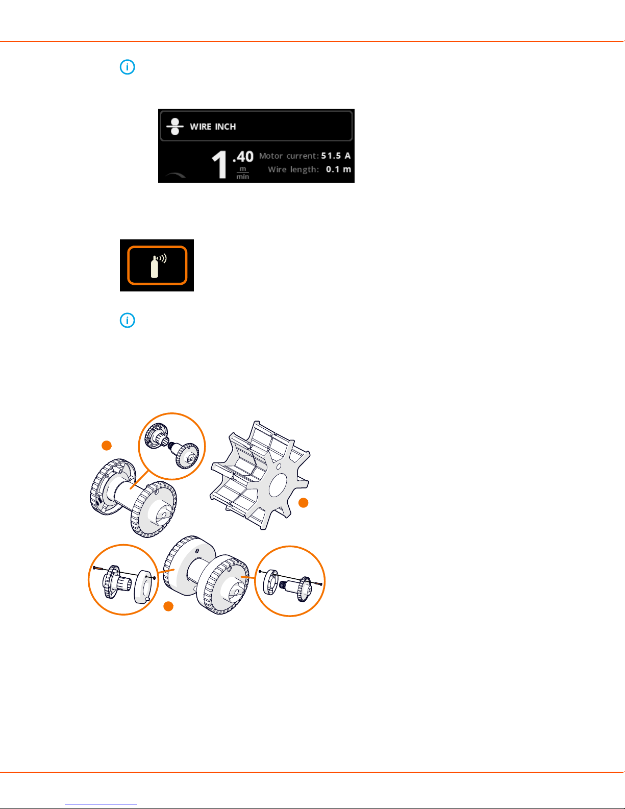
Wire spools
A
B
C
X8 MIG Welder has three different wire spool hub options available for different wire spools:
A. Standard spool
B. Spool hub for the small wire spool
Attach the extension pieces to the standard spool halves with a screw.
C. Spool hub for the wire spool with a large center hole
OPERATING MANUAL | EN 49
©
KEMPPI 2017 | 1817
Page 50

X8 MIG WELDER 2.4 Installation
All parts are delivered with the wire feeder.
Pull the spool halves to detach them. There is also a screw in the center of the hub that you can
use.
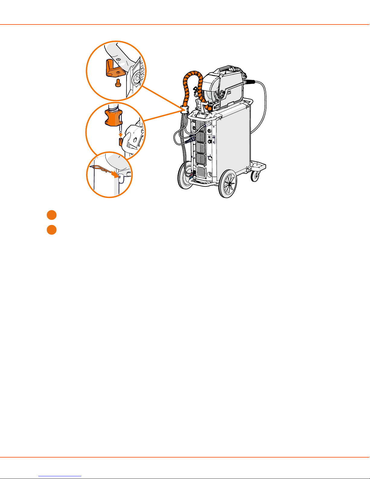
2.4.3.6 Attaching interconnection cable to strain relief
To ease the installation of the interconnection cable and to prevent any unnecessary strain on the
cable connectors, attach both ends of the interconnection cable bundle to a strain relief.
Proceed as follows:
Attach the strain relief holder to the transportation handle at the rear of the power source.
1.
Fasten the strain relief holder with a bolt from below.
Take the power source end of the interconnection cable and insert the strain relief pin to the
2.
strain relief holder.
Note:
If the wire feeder is detached from the power source, insert the strain relief pin to the
holder from below.
Note:
If the wire feeder is on the power source, insert the strain relief pin to the holder
from above.
OPERATING MANUAL | EN 50
©
KEMPPI 2017 | 1817
Page 51
X8 MIG WELDER 2.4 Installation
Insert the supplied locking pin through the hole in the strain relief pin.
3.
Route the cable bundle from the back of the power source and attach the strain relief in the
4.
other end of the cable to the left-hand side of the wire feeder. For more information, see .
2.4.4 Cables installation
For a detailed description of the power source and wire feeder cabling, see Installing
interconnection cable. For a full overview of the cabling, see Cabling diagram.
2.4.4.1 Installing interconnection cable
Install the interconnection cable first to the the wire feeder and then to the power source.
Proceed as follows:
OPERATING MANUAL | EN 51
©
KEMPPI 2017 | 1817
Page 52

X8 MIG WELDER 2.4 Installation
Connect the interconnection cable to the wire feeder
1.
a) Lift the cable cabinet latch to reveal the connectors.
b) Connect the welding current cable to the wire feeder. Push the cable as far as it goes and
turn the connector clockwise to tighten the cable to its place.
Caution:
Tighten the welding current cable as much as you can by hand. If the welding
current cable connection is loose, it may overheat.
c) Push the shielding gas hose towards the shielding gas hose connector base until it locks
down.
d) Attach the strain relief to the slot on the wire feeder.
e) Lock the strain relief latch to secure the strain relief.
f) Connect the control cable to the connector. Rotate the collar clockwise to lock it in place.
g) Connect the measurement cable to the connector. Rotate the collar clockwise to lock it in
place.
h) If you have the optional cooler, pull the cover over the cooling water hoses' slot to remove
it.
OPERATING MANUAL | EN 52
©
KEMPPI 2017 | 1817
Page 53

X8 MIG WELDER 2.4 Installation
i) Connect the cooling water hoses to the slot.
j) Close and lock the cable cabinet door.
Note:
When connecting the cables to the wire feeder, route the cables neatly so that the
cable cabinet door closes properly.
Connect the interconnection cable to the power source.
2.
a) Connect the welding current cable to the plus (+) side connector (1) on the power source.
The interconnection cable crosses from the wire feeder to the power source connector
diagonally.
Note:
If two wire feeders are connected to a power source, connect the interconnection
cable upright: from the wire feeder on the left to the connector (1) on the left.
b) Connect the earth return cable to the minus (-) side connector (2).
c) Connect the measurement cable to the measurement cable connector (4).
d) Connect the control cable to the control cable connector (3) on the same side as the
measurement cable.
e) If the water cooler is present, use the red connector (5) for the hose that goes to the
cooler.
OPERATING MANUAL | EN 53
©
KEMPPI 2017 | 1817
Page 54

X8 MIG WELDER 2.4 Installation
f) If the water cooler is present, use the blue connector (6) for the hose that comes from the
cooler.
g) If you need shielding gas, connect the shielding gas hose to the gas cylinder.
The power source can be connected to two wire feeders at the same time.
Caution:
Ensure that you have connected and tightened all the cables properly.
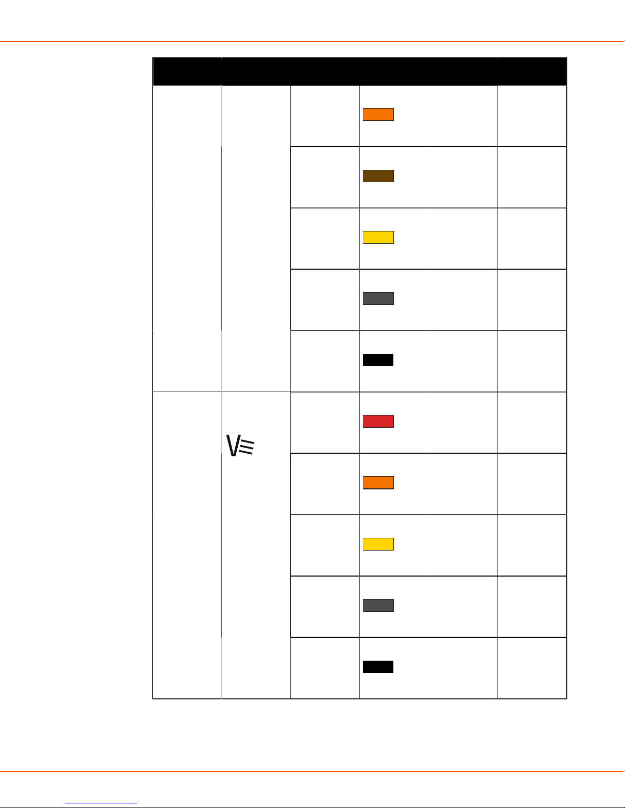
2.4.4.2 Cabling diagram
Connect the interconnection cables to power source and wire feeder. The figure below shows the
cables with colors to facilitate the identification.
Figure 3: Interconnection cabling for power source and wire feeder
Table 3: Color codes
Welding current cable
Shielding gas hose
Control cable
OPERATING MANUAL | EN 54
©
KEMPPI 2017 | 1817
Page 55

X8 MIG WELDER 2.4 Installation
Measurement cable
Coolant input and output hoses
Earth return cable
2.4.5 Control Pad installation
This chapter describes the control pad installation.
For information on operating Control Pad, see Control Pad on page 94.
2.4.5.1 Wireless connection
Control Pad connects wirelessly to X8 Wire Feeder. If there are two wire feeders in the system,
choose which one to connect to. Control Pad can be connected to X8 Power Source in
applications where no wire feeder is needed, such as stick welding or gouging.
To set up a wired connection between Control Pad and the power source or the wire feeder, see
Wired connection on page 58.
If Control Pad is not connected, you see this info message on the display.
OPERATING MANUAL | EN 55
©
KEMPPI 2017 | 1817
Page 56

X8 MIG WELDER 2.4 Installation
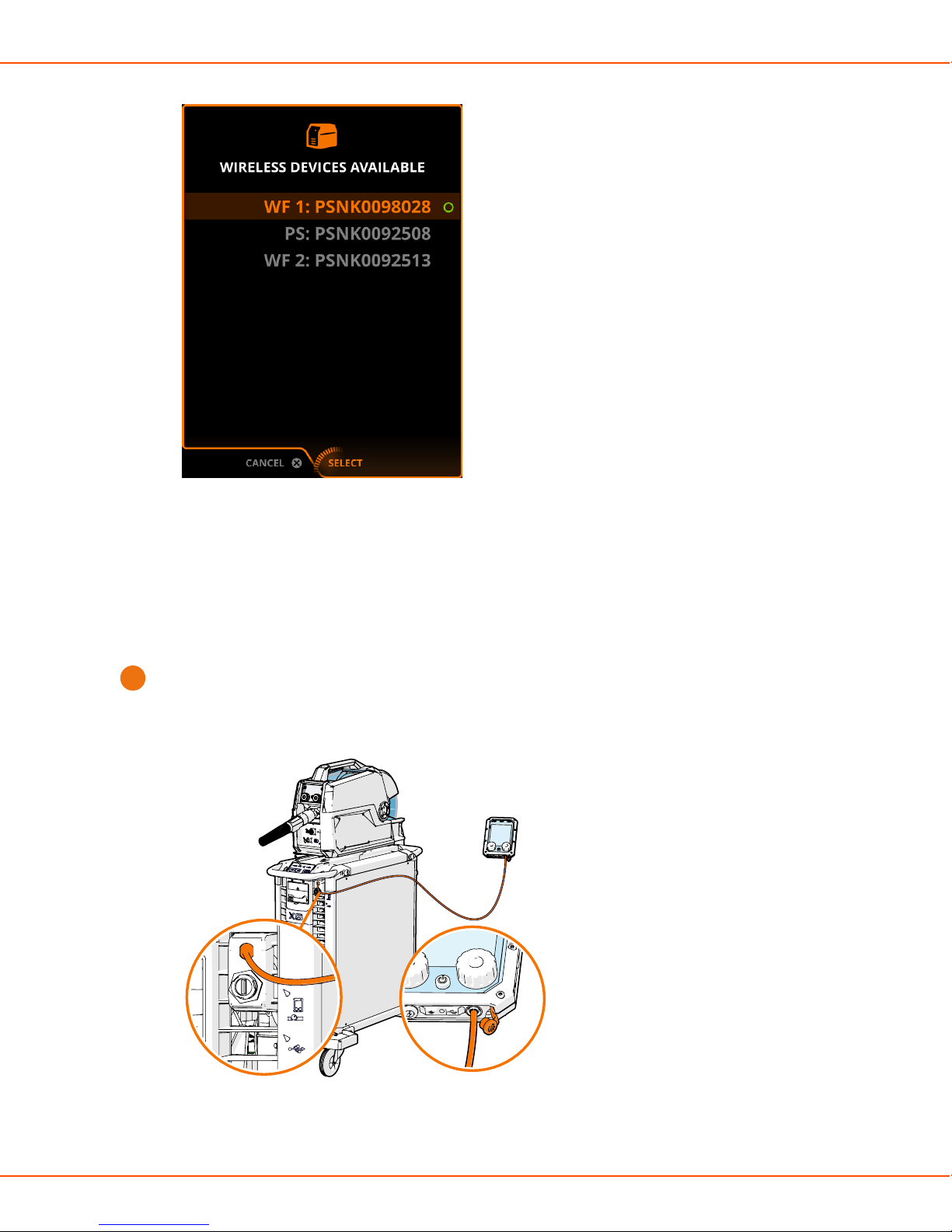
Proceed as follows:
To connect Control Pad wirelessly to a wire feeder or power source:
1.
a) Press the wireless pairing button on the power source indicator panel.
The led on the power source begins to blink when it is searching for Control Pad.
The serial numbers of the nearby available wire feeders or power sources appear on
Control Pad's display.
Note:
When there are wire feeders connected to the welding system, pressing the
wireless pairing button allows you to connect Control Pad to a wire feeder. When
there are no wire feeders connected to the system, Control Pad allows you to
connect to a power source.
OPERATING MANUAL | EN 56
©
KEMPPI 2017 | 1817
Page 57

X8 MIG WELDER 2.4 Installation
Figure 4: Connecting to wire feeder Figure 5: Connecting to power source
b) Move focus to select the connection and press the green button.
Note:
The connection list shows the serial numbers of the available wire feeders and a
power source. Check the serial number on the device rating plate.
A connection forms between the wire feeder or power source and Control Pad. The led on
the power source lights up permanently.
Note:
Once you have created the connection, Control Pad tries to reconnect if you take
it out of the connection distance. Select Disconnect on Control Pad to disconnect
the connection.
You can also connect Control Pad to the wire feeder through the wire feeder control panel if
2.
the wire feeder is far from the power source.
a) Go to Settings > Wireless devices > Connect.
The wire feeder connects automatically to Control Pad.
If the buttons of the power source and wire feeder are unreachable:
3.
a) Go to Settings > WirelessDevicesAvailable in Control Pad.
OPERATING MANUAL | EN 57
©
KEMPPI 2017 | 1817
Page 58
X8 MIG WELDER 2.4 Installation
b) Move focus to a wire feeder or a power source.
c) Press the green button.
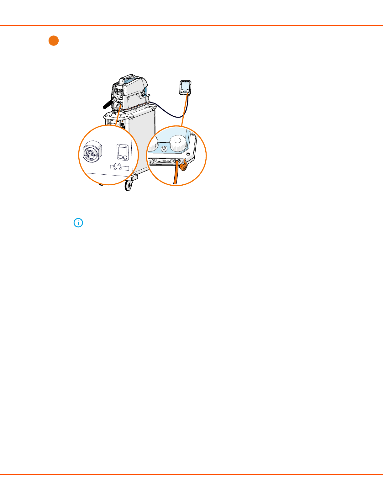
2.4.5.2 Wired connection
Control Pad makes a wired connection with X8 Power Source and X8 Wire Feeder. Connect
Control Pad to a wired connection, when wireless connection is unavailable.
Proceed as follows:
To make a wired connection between Control Pad and the power source:
1.
a) Plug the combo cable to the Control Pad connector of the power source.
The connector is marked with a Control Pad icon.
b) Plug the combo cable to the combo cable port on the bottom of Control Pad.
OPERATING MANUAL | EN 58
©
KEMPPI 2017 | 1817
Page 59
X8 MIG WELDER 2.4 Installation
To make a wired connection between Control Pad and the wire feeder:
2.
a) Plug the combo cable to the remote control connector of the wire feeder.
The connector is marked with a Control Pad icon.
b) Plug the combo cable to the combo cable port on the bottom of Control Pad.
Note: Use mainly the external charger to charge Control Pad.
2.4.5.3 Suspending Control Pad
Control Pad has a hook, which you can use to suspend it on the welding machine or other
suitable place. Control Pad also has a loop in each corner, which you can use for a sling.
OPERATING MANUAL | EN 59
©
KEMPPI 2017 | 1817
Page 60

X8 MIG WELDER 2.4 Installation
2.4.6 Welding gun installation
Connect the welding gun to the wire feeder, prepare it for use, and change consumable parts.
2.4.6.1 Preparing and connecting welding gun
The X8 MIG Gun has been preassembled by the manufacturer: the wire liner, contact tip and gas
nozzle are premounted. To start using the gun, proceed as follows:
Check that the wire liner, contact tip, gas nozzle are suitable for the job. Change if needed. If
1.
your setup includes a gas-cooled gun, you can also change the neck.
Attach the pistol grip handle, if suitable for the job.
2.
Attach X8 Gun Remote Control, if suitable for the job (optional, later release).
3.
Connect the welding gun to the wire feeder: Push the welding gun connector into the wire
4.
feeder gun adapter, and hand-tighten the collar.
OPERATING MANUAL | EN 60
©
KEMPPI 2017 | 1817
Page 61

X8 MIG WELDER 2.4 Installation
Note:
X8 MIG Guns connect to X8 Wire Feeder with a special Kemppi Gun Adapter that
enables, among other things, accurate measurement of the actual arc voltage and
the usage of the remote control (available in a later release). Therefore, X8 MIG Guns
are only compatible with X8 Wire Feeder.
If your setup includes a water-cooled gun, connect the cooling hoses to the wire feeder. The
5.
coolant inlet hose is marked with blue and the coolant outlet hose with red.
Dress the sharp filler wire tip before loading to improve wire loading and consumables life.
6.
Load the filler wire by pressing the Wire inch button.
7.
OPERATING MANUAL | EN 61
©
KEMPPI 2017 | 1817
Page 62
X8 MIG WELDER 2.4 Installation
Trim the excess filler wire at a slight angle to improve ignition.
8.
Check the gas flow rate.
9.
The welding gun is now ready for use. When not using the gun, you can keep it in the gun holder
on the side of the wire feeder.
2.4.6.2 Replacing consumable parts of welding gun
Select a suitable contact tip, gas nozzle, neck and wire liner according to the job. See also how to
change the feed rolls of the wire feeder accordingly: Replacing feed rolls on page 38.
Compatibility of welding gun parts and models
Table 4: Codes used in the tables
Code Meaning
Standard Part of the standard delivery
X
- Not compatible
Compatible, but not part of the the standard
delivery
Contact tips for water-cooled guns
Contact tip
W007919
0.8/D10 M8 /
CEP
X8300403500
X8 MIG Gun
400-W 3.5m
X X X X
X8300405000
X8 MIG Gun
400-W 5.0m
X8300503500
X8 MIG Gun
500-W 3.5m
X8300505000
X8 MIG Gun
500-W 5.0m
W007920
0.9/D10 M8 /
CEP
OPERATING MANUAL | EN 62
X X X X
©
KEMPPI 2017 | 1817
Page 63
X8 MIG WELDER 2.4 Installation
Contact tip
X8300403500
X8 MIG Gun
400-W 3.5m
X8300405000
X8 MIG Gun
400-W 5.0m
W006826
1.0/D10 M8 /
Standard Standard X X
CEP
W006518
1.2/D10 M8 /
X X Standard Standard
CEP
W010309
1.4/D10 M8 /
X X X X
CEP
W007921
1.6/D10 M8 /
X X X X
CEP
Contact tip adapters for water-cooled guns
X8300503500
X8 MIG Gun
500-W 3.5m
X8300505000
X8 MIG Gun
500-W 5.0m
Contact tip
adapter
X8300403500
X8 MIG Gun
400-W 3.5m
W006182
Standard Standard - -
M8 PMT42W
W004508
- - Standard Standard
M8 PMT52W
Gas diffusers for water-cooled guns
Gas diffuser X8300403500
X8 MIG Gun
400-W 3.5m
W006146
PMT42W
modified
W004505
PMT42 modified
Standard Standard - -
- - Standard Standard
X8300405000
X8 MIG Gun
400-W 5.0m
X8300405000
X8 MIG Gun
400-W 5.0m
X8300503500
X8 MIG Gun
500-W 3.5m
X8300503500
X8 MIG Gun
500-W 3.5m
X8300505000
X8 MIG Gun
500-W 5.0m
X8300505000
X8 MIG Gun
500-W 5.0m
OPERATING MANUAL | EN 63
©
KEMPPI 2017 | 1817
Page 64

X8 MIG WELDER 2.4 Installation
Gas nozzles for water-cooled guns
Gas nozzle X8300403500
X8 MIG Gun
400-W 3.5m
W012528
Relicool400
Standard Standard - -
insulated
W012540
Relicool500
- - Standard Standard
insulated
Wire liners for water-cooled guns
Wire liner X8300403500
X8 MIG Gun
400-W 3.5m
W012611
X8 liner RED
3.5m
Standard - Standard -
X8300405000
X8 MIG Gun
400-W 5.0m
X8300405000
X8 MIG Gun
400-W 5.0m
X8300503500
X8 MIG Gun
500-W 3.5m
X8300503500
X8 MIG Gun
500-W 3.5m
X8300505000
X8 MIG Gun
500-W 5.0m
X8300505000
X8 MIG Gun
500-W 5.0m
W012612
X8 liner RED
5.0m
W012613
X8 liner YE 3.5m
W012614
X8 liner YE 5.0m
W012622
X8 liner 3.5m
Ø1,5/5,9 DL-Chili
W012623
X8 liner 5.0m
Ø1,5/5,9 DL-Chili
W012624
X8 liner 3.5m
Ø2,0/5,9 DL-Chili
- Standard - Standard
X - X -
- X - X
X - X -
- X - X
X - X -
W012625
X8 liner 5.0m
- X - X
Ø2,0/5,9 DL-Chili
OPERATING MANUAL | EN 64
©
KEMPPI 2017 | 1817
Page 65

X8 MIG WELDER 2.4 Installation
Wire liner X8300403500
X8300405000
X8 MIG Gun
400-W 3.5m
W012626
X8 liner 3.5m
X - X -
Ø2,5/5,9 DL-Chili
W012627
X8 liner 5.0m
- X - X
Ø2,5/5,9 DL-Chili
Liner guide tubes for water-cooled guns
Liner guide
tube
W009276
Guide tube out
0.6 LTGY Plastic
X8300403500
X8 MIG Gun
400-W 3.5m
X X X X
X8300405000
X8 MIG Gun
400-W 5.0m
X8 MIG Gun
400-W 5.0m
X8300503500
X8 MIG Gun
500-W 3.5m
X8300503500
X8 MIG Gun
500-W 3.5m
X8300505000
X8 MIG Gun
500-W 5.0m
X8300505000
X8 MIG Gun
500-W 5.0m
W011867
Guide tube out
0.8-0.9 WH
Plastic
W011868
Guide tube out
1.0 RD Plastic
W011869
Guide tube out
1.2 OG Plastic
W011870
Guide tube out
1.4 BN Plastic
W011871
Guide tube out
1.6 YE Plastic
W011886
Guide tube out
0.6 LTGY Metal
X X X X
Standard Standard X X
X X Standard Standard
X X X X
X X X X
X X X X
OPERATING MANUAL | EN 65
©
KEMPPI 2017 | 1817
Page 66

X8 MIG WELDER 2.4 Installation
Liner guide
tube
W011887
Guide tube out
0.8-0.9 WH
Metal
W011888
Guide tube out
1.0 RD Metal
W011889
Guide tube out
1.2 OG Metal
W011890
Guide tube out
1.4 BN Metal
W011891
Guide tube out
1.4-1.6 YE Metal
X8300403500
X8 MIG Gun
400-W 3.5m
X X X X
X X X X
X X X X
X X X X
X X X X
X8300405000
X8 MIG Gun
400-W 5.0m
X8300503500
X8 MIG Gun
500-W 3.5m
X8300505000
X8 MIG Gun
500-W 5.0m
Contact tips for gas-cooled guns
Contact tipX8301203500
X8 MIG
Gun 200-
G 3.5m
W012130
Bored 0.8/
X X X X X X
M10X1
W012131
Bored 0.9/
X X X X X X
M10X1
W012132
Standard Standard Standard Standard X X
Bored 1.0/
M10X1
W012134
Bored 1.2/
X X X X Standard Standard
M10X1
X8301205000
X8 MIG
Gun 200-
G 5.0m
X8301303500
X8 MIG
Gun 300-
G 3.5m
X8301305000
X8 MIG
Gun 300-
G 5.0m
X8301403500
X8 MIG
Gun 400-
G 3.5m
X8301405000
X8 MIG
Gun 400-
G 5.0m
OPERATING MANUAL | EN 66
©
KEMPPI 2017 | 1817
Page 67

X8 MIG WELDER 2.4 Installation
Contact tipX8301203500
X8 MIG
Gun 200-
G 3.5m
X8301205000
X8 MIG
Gun 200-
G 5.0m
X8301303500
W012135
Bored 1.4/
X X X X X X
M10X1
W011758
Bored 1.6/
X X X X X X
M10X1
Contact tip adapters for gas-cooled guns
Contact tip
adapter
W006182
M8
PMT42W
X8301203500
X8 MIG
Gun 200-
G 3.5m
- - - - - -
X8301205000
X8 MIG
Gun 200-
G 5.0m
X8301303500
X8 MIG
Gun 300-
G 3.5m
X8 MIG
Gun 300-
G 3.5m
X8301305000
X8 MIG
Gun 300-
G 5.0m
X8301305000
X8 MIG
Gun 300-
G 5.0m
X8301403500
X8 MIG
Gun 400-
G 3.5m
X8301403500
X8 MIG
Gun 400-
G 3.5m
X8301405000
X8 MIG
Gun 400-
G 5.0m
X8301405000
X8 MIG
Gun 400-
G 5.0m
W004508
M8
- - - - - -
PMT52W
W011483
Standard Standard Standard Standard Standard Standard
G8
Gas nozzles for gas-cooled guns
Gas nozzle X8301203500
X8 MIG
Gun 200-
G 3.5m
W011478
Standard Standard Standard Standard - -
G8 200,
300
Gasnozzle
W011472
- - - - Standard Standard
G8 400
Gasnozzle
X8301205000
X8 MIG
Gun 200-
G 5.0m
X8301303500
X8 MIG
Gun 300-
G 3.5m
X8301305000
X8 MIG
Gun 300-
G 5.0m
X8301403500
X8 MIG
Gun 400-
G 3.5m
X8301405000
X8 MIG
Gun 400-
G 5.0m
OPERATING MANUAL | EN 67
©
KEMPPI 2017 | 1817
Page 68

X8 MIG WELDER 2.4 Installation
Gas nozzle X8301203500
X8 MIG
Gun 200-
G 3.5m
W011958
X X X X - -
X8301205000
X8 MIG
Gun 200-
G 5.0m
X8 200,
300 Root
gasnozzle
W011953
X X X X - -
X8 200, 300
Narrow gap
gasnozzle
Wire liners for gas-cooled guns
Wire liner X8301203500
X8 MIG
Gun 200-
G 3.5m
W012361
Standard - Standard - Standard -
X8301205000
X8 MIG
Gun 200-
G 5.0m
X8301303500
X8 MIG
Gun 300-
G 3.5m
X8301303500
X8 MIG
Gun 300-
G 3.5m
X8301305000
X8 MIG
Gun 300-
G 5.0m
X8301305000
X8 MIG
Gun 300-
G 5.0m
X8301403500
X8 MIG
Gun 400-
G 3.5m
X8301403500
X8 MIG
Gun 400-
G 3.5m
X8301405000
X8 MIG
Gun 400-
G 5.0m
X8301405000
X8 MIG
Gun 400-
G 5.0m
X8
Changeable
neck liner
RED 3.5m
W012362
X8
Changeable
neck liner
RED 5.0m
W012363
X8
Changeable
neck liner
YE 3.5m
W012364
X8
Changeable
neck liner
YE 5.0m
- Standard - Standard - Standard
X - X - X -
- X - X - X
OPERATING MANUAL | EN 68
©
KEMPPI 2017 | 1817
Page 69

X8 MIG WELDER 2.4 Installation
Wire liner X8301203500
X8 MIG
Gun 200-
G 3.5m
W012355
X - X - X -
X8
Changeable
neck
CHliner
1,5/5,9
3.5m
W012351
- X - X - X
X8
Changeable
neck
CHliner
1,5/5,9
5.0m
W012356
X - X - X -
X8
Changeable
neck
CHliner
2,0/5,9
3.5m
X8301205000
X8 MIG
Gun 200-
G 5.0m
X8301303500
X8 MIG
Gun 300-
G 3.5m
X8301305000
X8 MIG
Gun 300-
G 5.0m
X8301403500
X8 MIG
Gun 400-
G 3.5m
X8301405000
X8 MIG
Gun 400-
G 5.0m
W012352
X8
Changeable
neck
CHliner
2,0/5,9
5.0m
W012357
X8
Changeable
neck
CHliner
2,5/5,9
3.5m
W012353
X8
Changeable
neck
CHliner
2,5/5,9
5.0m
- X - X - X
X - X - X -
- X - X - X
OPERATING MANUAL | EN 69
©
KEMPPI 2017 | 1817
Page 70

X8 MIG WELDER 2.4 Installation
Wire liners for gas-cooled guns
Wire liner X8301203500
X8 MIG
Gun 200-
G 3.5m
W012361
Standard - Standard - Standard -
X8
Changeable
neck liner
RED 3.5m
W012362
- Standard - Standard - Standard
X8
Changeable
neck liner
RED 5.0m
W012363
X - X - X -
X8
Changeable
neck liner
YE 3.5m
W012364
- X - X - X
X8301205000
X8 MIG
Gun 200-
G 5.0m
X8301303500
X8 MIG
Gun 300-
G 3.5m
X8301305000
X8 MIG
Gun 300-
G 5.0m
X8301403500
X8 MIG
Gun 400-
G 3.5m
X8301405000
X8 MIG
Gun 400-
G 5.0m
X8
Changeable
neck liner
YE 5.0m
W012355
X8
Changeable
neck
CHliner
1,5/5,9
3.5m
W012351
X8
Changeable
neck
CHliner
1,5/5,9
5.0m
X - X - X -
- X - X - X
OPERATING MANUAL | EN 70
©
KEMPPI 2017 | 1817
Page 71

X8 MIG WELDER 2.4 Installation
Wire liner X8301203500
X8 MIG
Gun 200-
G 3.5m
W012356
X - X - X -
X8
Changeable
neck
CHliner
2,0/5,9
3.5m
W012352
- X - X - X
X8
Changeable
neck
CHliner
2,0/5,9
5.0m
W012357
X - X - X -
X8
Changeable
neck
CHliner
2,5/5,9
3.5m
X8301205000
X8 MIG
Gun 200-
G 5.0m
X8301303500
X8 MIG
Gun 300-
G 3.5m
X8301305000
X8 MIG
Gun 300-
G 5.0m
X8301403500
X8 MIG
Gun 400-
G 3.5m
X8301405000
X8 MIG
Gun 400-
G 5.0m
W012353
- X - X - X
X8
Changeable
neck
CHliner
2,5/5,9
5.0m
Wire liners for gas-cooled guns
Wire liner X8301203500
X8 MIG
Gun 200-
G 3.5m
W012361
Standard - Standard - Standard -
X8
Changeable
neck liner
RED 3.5m
X8301205000
X8 MIG
Gun 200-
G 5.0m
X8301303500
X8 MIG
Gun 300-
G 3.5m
X8301305000
X8 MIG
Gun 300-
G 5.0m
X8301403500
X8 MIG
Gun 400-
G 3.5m
X8301405000
X8 MIG
Gun 400-
G 5.0m
OPERATING MANUAL | EN 71
©
KEMPPI 2017 | 1817
Page 72

X8 MIG WELDER 2.4 Installation
Wire liner X8301203500
X8 MIG
Gun 200-
G 3.5m
W012362
- Standard - Standard - Standard
X8
Changeable
neck liner
RED 5.0m
W012363
X - X - X -
X8
Changeable
neck liner
YE 3.5m
W012364
- X - X - X
X8
Changeable
neck liner
YE 5.0m
X8301205000
X8 MIG
Gun 200-
G 5.0m
X8301303500
X8 MIG
Gun 300-
G 3.5m
X8301305000
X8 MIG
Gun 300-
G 5.0m
X8301403500
X8 MIG
Gun 400-
G 3.5m
X8301405000
X8 MIG
Gun 400-
G 5.0m
W012355
X8
Changeable
neck
CHliner
1,5/5,9
3.5m
W012351
X8
Changeable
neck
CHliner
1,5/5,9
5.0m
W012356
X8
Changeable
neck
CHliner
2,0/5,9
3.5m
X - X - X -
- X - X - X
X - X - X -
OPERATING MANUAL | EN 72
©
KEMPPI 2017 | 1817
Page 73
X8 MIG WELDER 2.4 Installation
Wire liner X8301203500
X8 MIG
Gun 200-
G 3.5m
W012352
- X - X - X
X8
Changeable
neck
CHliner
2,0/5,9
5.0m
W012357
X - X - X -
X8
Changeable
neck
CHliner
2,5/5,9
3.5m
W012353
- X - X - X
X8
Changeable
neck
CHliner
2,5/5,9
5.0m
X8301205000
X8 MIG
Gun 200-
G 5.0m
X8301303500
X8 MIG
Gun 300-
G 3.5m
X8301305000
X8 MIG
Gun 300-
G 5.0m
X8301403500
X8 MIG
Gun 400-
G 3.5m
X8301405000
X8 MIG
Gun 400-
G 5.0m
Liner guide tubes for gas-cooled guns
Liner
guide tube
W009276
Guide tube
out 0.6
LTGY Plastic
W011867
Guide tube
out 0.8-0.9
WH Plastic
W011868
Guide tube
out 1.0 RD
Plastic
X8301203500
X8 MIG
Gun 200-
G 3.5m
X8301205000
X8 MIG
Gun 200-
G 5.0m
X X X X X X
X X X X X X
Standard Standard Standard Standard X X
X8301303500
X8 MIG
Gun 300-
G 3.5m
X8301305000
X8 MIG
Gun 300-
G 5.0m
X8301403500
X8 MIG
Gun 400-
G 3.5m
X8301405000
X8 MIG
Gun 400-
G 5.0m
OPERATING MANUAL | EN 73
©
KEMPPI 2017 | 1817
Page 74

X8 MIG WELDER 2.4 Installation
Liner
guide tube
W011869
Guide tube
out 1.2 OG
Plastic
W011870
Guide tube
out 1.4 BN
Plastic
W011871
Guide tube
out 1.6 YE
Plastic
W011886
Guide tube
out 0.6
LTGY Metal
X8301203500
X8 MIG
Gun 200-
G 3.5m
X X X X Standard Standard
X X X X X X
X X X X X X
X X X X X X
X8301205000
X8 MIG
Gun 200-
G 5.0m
X8301303500
X8 MIG
Gun 300-
G 3.5m
X8301305000
X8 MIG
Gun 300-
G 5.0m
X8301403500
X8 MIG
Gun 400-
G 3.5m
X8301405000
X8 MIG
Gun 400-
G 5.0m
W011887
Guide tube
out 0.8-0.9
WH Metal
W011888
Guide tube
out 1.0 RD
Metal
W011889
Guide tube
out 1.2 OG
Metal
W011890
Guide tube
out 1.4 BN
Metal
W011891
Guide tube
out 1.4-1.6
YE Metal
X X X X X X
X X X X X X
X X X X X X
X X X X X X
X X X X X X
OPERATING MANUAL | EN 74
©
KEMPPI 2017 | 1817
Page 75
X8 MIG WELDER 2.4 Installation
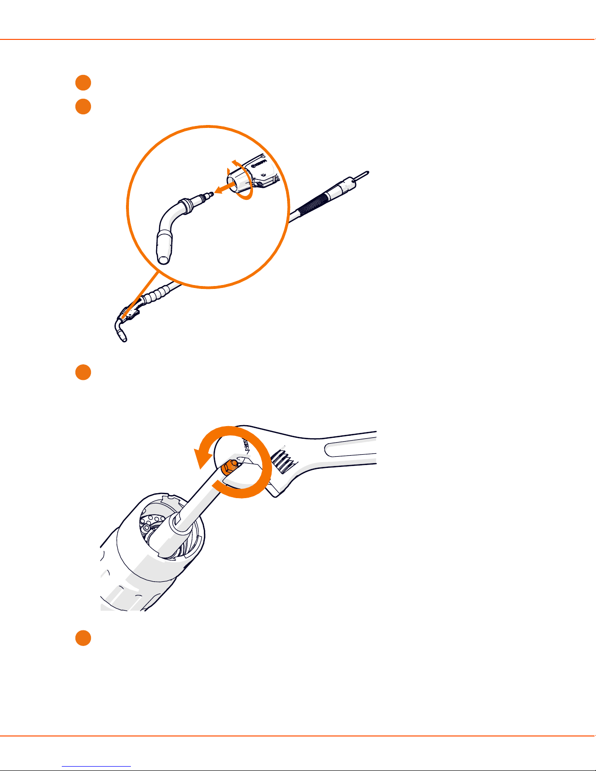
Changing liner (gas-cooled gun)
Lay the welding gun cable straight on a flat surface.
1.
Loosen the neck tightener by rotating it half a turn, and remove the neck.
2.
Remove the guide nut from the tip of the sleeve.
3.
Remove the sleeve and pull out the liner. Make sure the cone and the seal slide out with the
4.
liner.
OPERATING MANUAL | EN 75
©
KEMPPI 2017 | 1817
Page 76

X8 MIG WELDER 2.4 Installation
1 2
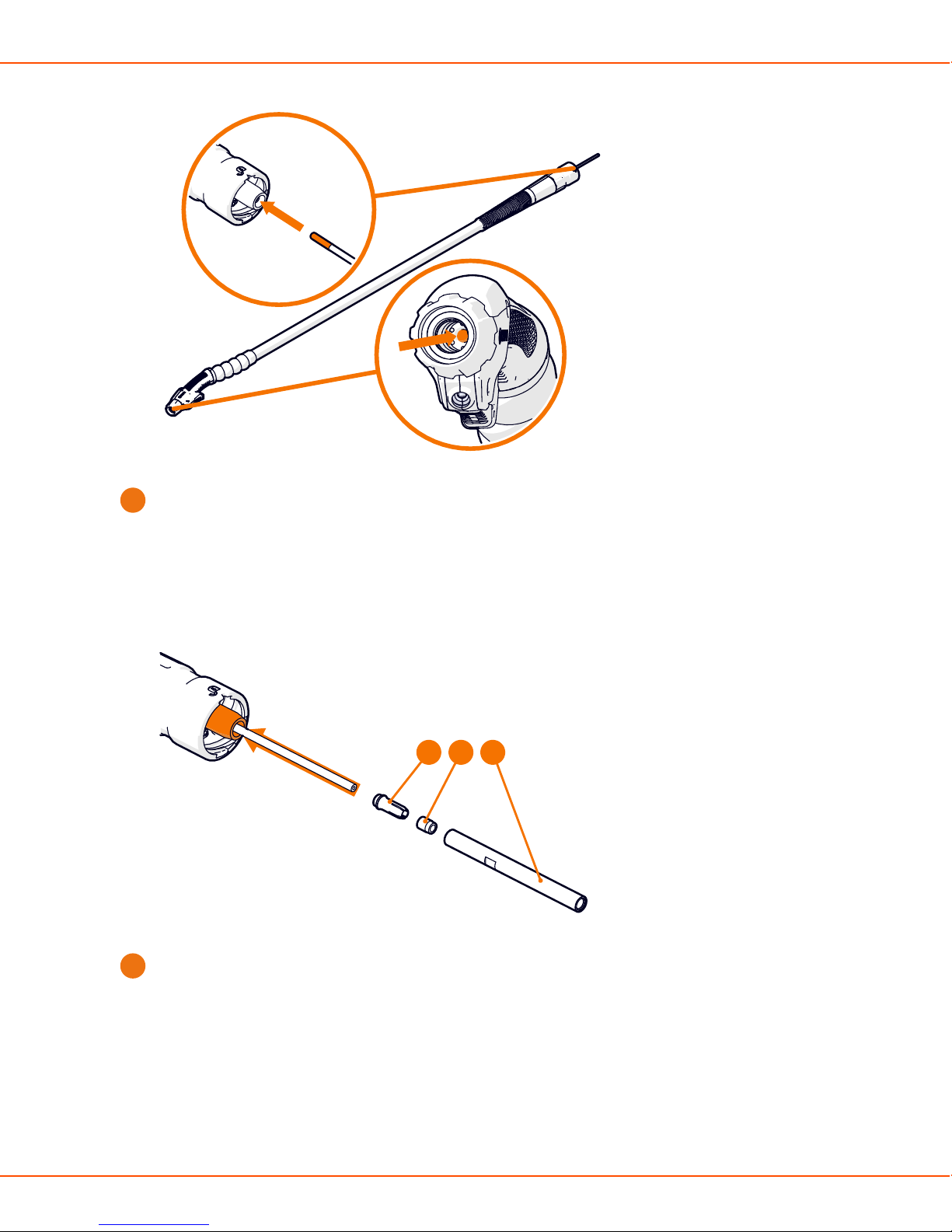
Load the new liner through the welding gun connector as far as you can push it. Check that
5.
you have pushed the liner far enough: the liner must be visible at the tip of the gun.
OPERATING MANUAL | EN 76
©
KEMPPI 2017 | 1817
Page 77
X8 MIG WELDER 2.4 Installation
Assemble the cone (1), seal (2) and sleeve (3) (supplied with the new liner) over the liner
6.
protruding from the welding gun connector. Tighten the sleeve as tight as possible with a
spanner.
1 2 3
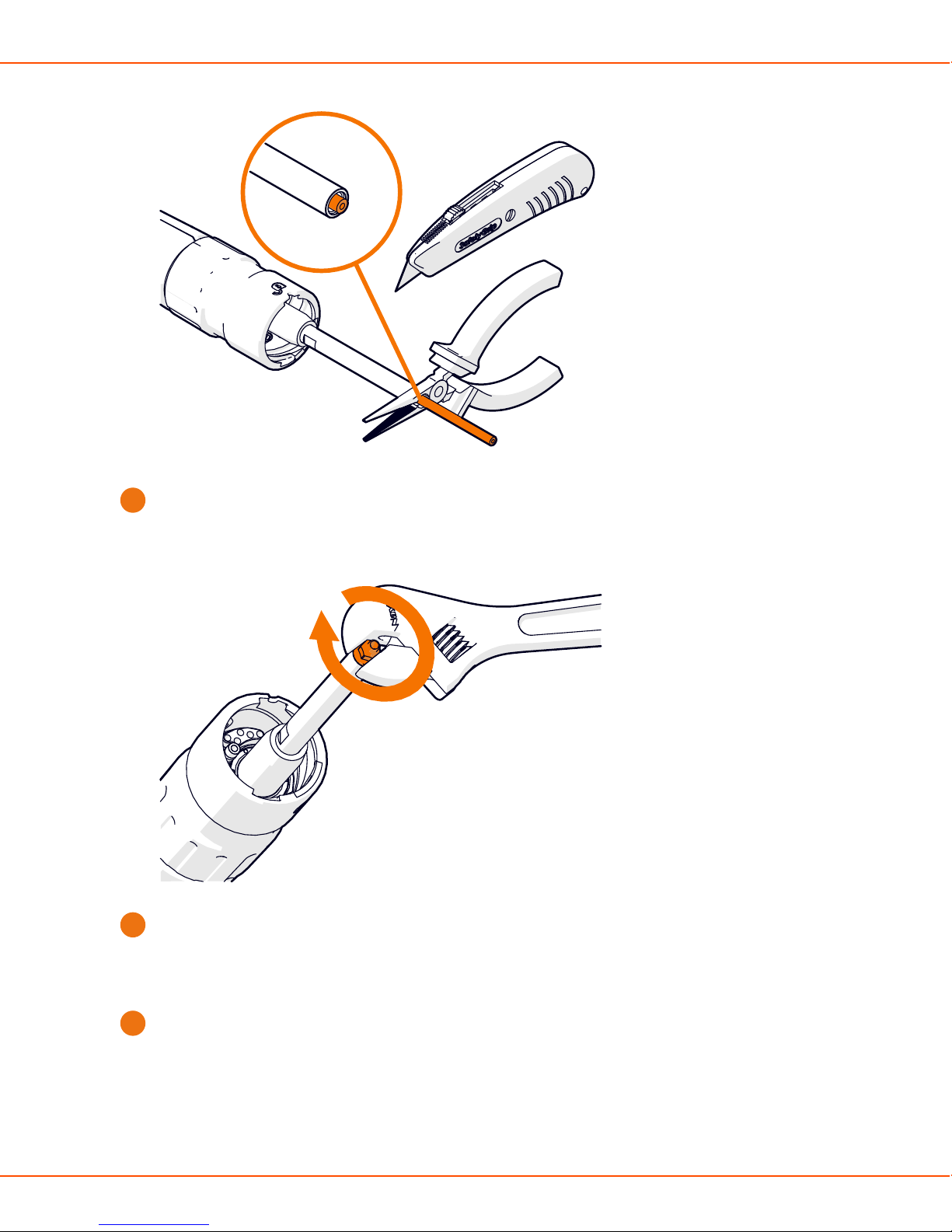
Cut the excessive liner (spiral liner with side cutting pliers, DL Chili liner with a carpet knife)
7.
leaving 1 - 2 mm.
OPERATING MANUAL | EN 77
©
KEMPPI 2017 | 1817
Page 78
X8 MIG WELDER 2.4 Installation
1-2 mm
Attach the guide nut at the tip of the sleeve.
8.
Re-assemble the neck and tighten the neck tightener to secure.
9.
Changing neck (gas-cooled gun)
You can change the neck easily, without tools.
Turn the neck tightener half a turn counter-clockwise to loosen it, and pull the neck out.
1.
OPERATING MANUAL | EN 78
©
KEMPPI 2017 | 1817
Page 79

X8 MIG WELDER 2.4 Installation
Push in the new neck and turn the neck tightener half a turn clockwise to secure it. Make sure
2.
you push the neck deep enough: When the neck is correctly inserted, the groove on the neck
is completely hidden under the neck tightener.
Note:
You can rotate the neck into different positions without loosening the neck tightener.
Changing gas nozzle (gas-cooled gun)
Screw the gas nozzle into its place.
OPERATING MANUAL | EN 79
©
KEMPPI 2017 | 1817
Page 80
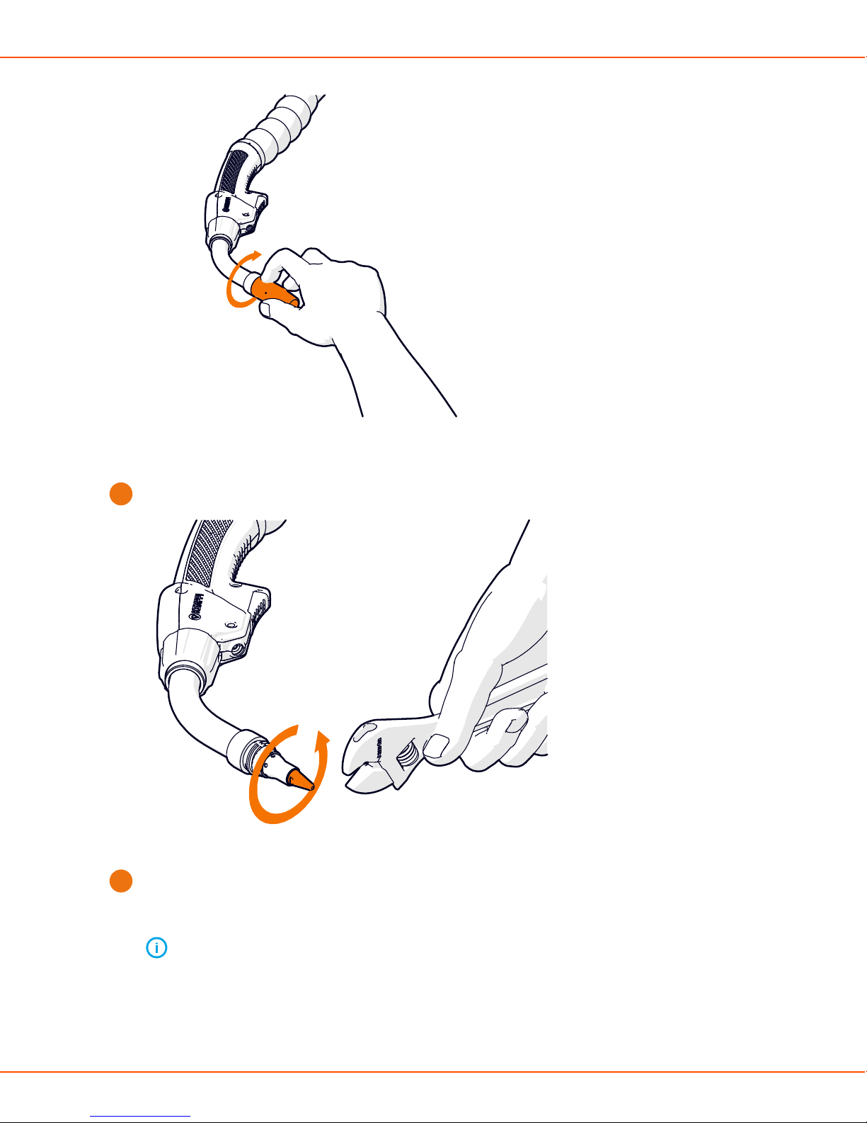
X8 MIG WELDER 2.4 Installation
Changing contact tip (gas-cooled gun)
Remove the contact tip.
1.
Replace the contact tip adapter / gas diffuser, if needed. Screw in and hand-tighten the new
2.
adapter as tight as possible (no tool is needed). Make sure there is no gap between the
contact tip adapter and the black plastic bushing.
Note:
It is important to tighten the adapter properly to enable a tight connection of the
contact tip to the gun.
OPERATING MANUAL | EN 80
©
KEMPPI 2017 | 1817
Page 81

X8 MIG WELDER 2.4 Installation
Screw in a new contact tip and tighten it with an appropriate tool. Some thread grooves on
3.
the contact tip remain visible when the contact tip is properly connected to the gun.
Changing wire liner (water-cooled gun)
Caution:
Use the correct wire liner. The tip of the filler wire may damage an incorrect liner.
Lay the welding gun cable straight on a flat surface.
1.
OPERATING MANUAL | EN 81
©
KEMPPI 2017 | 1817
Page 82

X8 MIG WELDER 2.4 Installation
Remove the guide nut from the tip of the sleeve.
2.
Remove the sleeve and pull out the liner together with the cone (1) and the seal (2).
3.
OPERATING MANUAL | EN 82
©
KEMPPI 2017 | 1817
Page 83

X8 MIG WELDER 2.4 Installation
1 2
Load the new liner through the welding gun connector until enough liner protrudes from the
4.
neck. Adjust the length according to the contact tip adapter.
Note:
Make sure the liner is properly inside the contact tip adapter before you cut the liner
at the connector end.
OPERATING MANUAL | EN 83
©
KEMPPI 2017 | 1817
Page 84

X8 MIG WELDER 2.4 Installation
Assemble the cone (1), seal (2) and sleeve (3) (supplied with the liner) over the liner
5.
protruding from the welding gun connector. Tighten the sleeve with a spanner to secure.
1 2 3
OPERATING MANUAL | EN 84
©
KEMPPI 2017 | 1817
Page 85
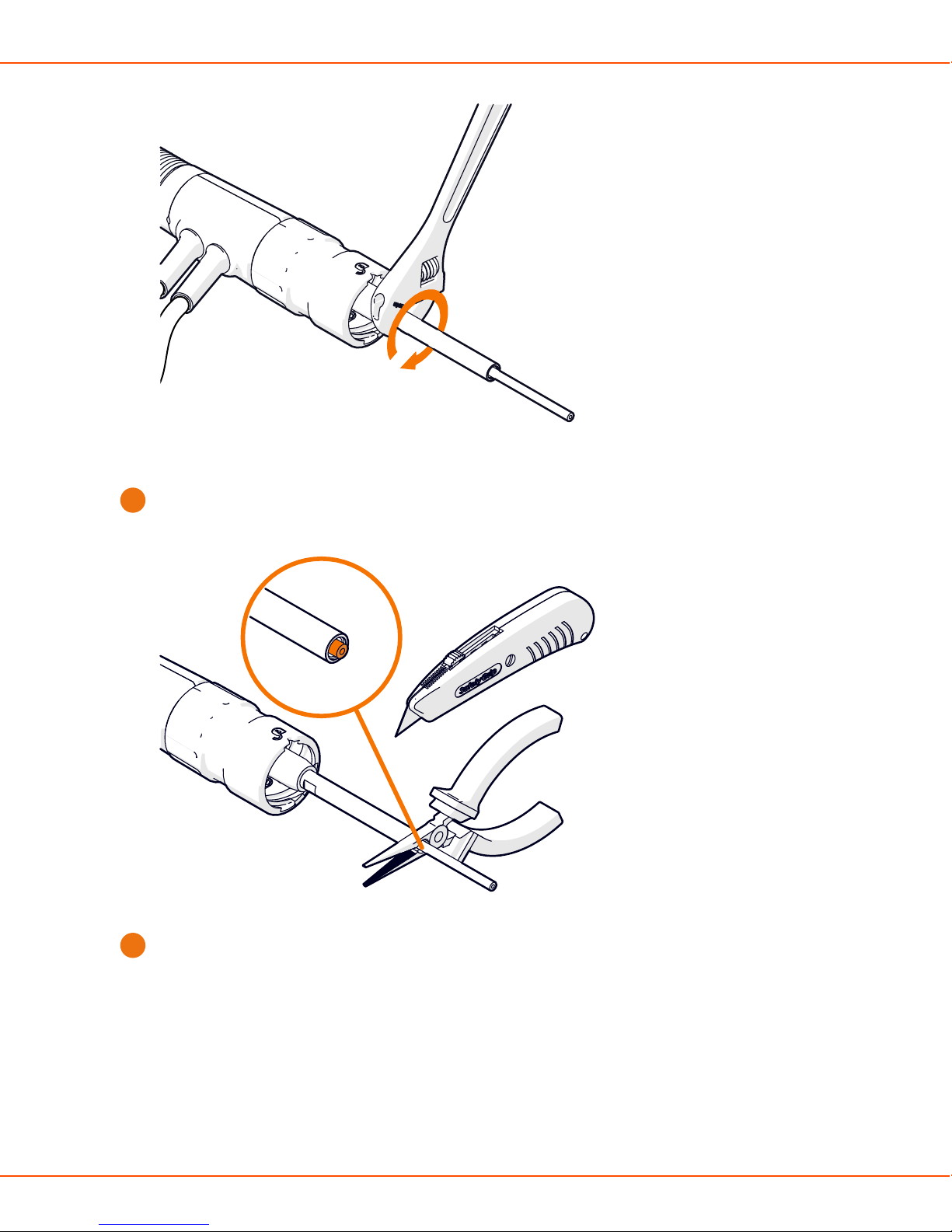
X8 MIG WELDER 2.4 Installation
Cut the excessive liner (spiral liner with side cutting pliers, DL Chili liner with a carpet knife)
6.
leaving 1 - 2 mm.
1-2 mm
Attach the guide nut at the tip of the sleeve.
7.
OPERATING MANUAL | EN 85
©
KEMPPI 2017 | 1817
Page 86

X8 MIG WELDER 2.4 Installation
Changing gas nozzle (water-cooled gun)
To remove the old gas nozzle, turn the nozzle slightly anti-clockwise and pull.
1.
Push the new nozzle in until it clicks firmly into place.
2.
OPERATING MANUAL | EN 86
©
KEMPPI 2017 | 1817
Page 87

X8 MIG WELDER 2.4 Installation
Changing contact tip (water-cooled gun)
Remove the gas nozzle and the contact tip.
1.
Replace the contact tip adapter (1) and gas diffuser (2), if needed. Screw in and tighten the
2.
new adapter with a tool.
Note:
It is important to tighten the adapter properly to enable a tight connection of the
contact tip to the gun.
OPERATING MANUAL | EN 87
©
KEMPPI 2017 | 1817
Page 88

X8 MIG WELDER 2.4 Installation
1 2
Screw in a new contact tip and tighten it properly with a tool.
3.
2.4.6.3 Installing pistol grip handle
The pistol grip handle is suitable for all X8 MIG Guns. The handle improves the ergonomics of
many welding positions.
To attact the pistol grip handle, align the grooves and pull the handle forward to attach the front
side (1), and then push the handle back to snap-lock it into its place (2).
OPERATING MANUAL | EN 88
©
KEMPPI 2017 | 1817
Page 89

X8 MIG WELDER 2.4 Installation
1
2
To detach the pistol grip handle, press the lock button at the back of the handle.
2.4.7 Lifting X8 MIG Welder
If you need to lift X8 MIG Welder, pay special attention to the safety measures. Follow the local
regulations.
Warning: Do not lift the welder with the gas cylinder.
Proceed as follows:
OPERATING MANUAL | EN 89
©
KEMPPI 2017 | 1817
Page 90
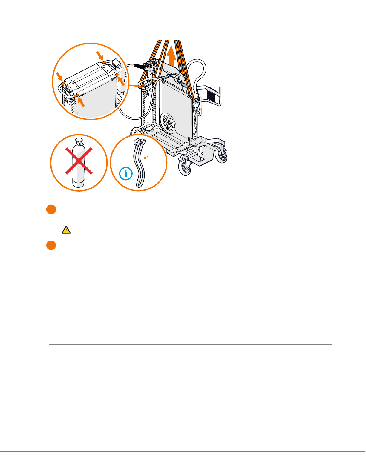
X8 MIG WELDER 2.4 Installation
Loop two lifting straps through the handle at the front and two straps through the handle at
1.
the back of the power source.
Caution: Place the straps as close to the power source as possible.
Lift steadily straight up.
2.
2.4.8 Purchasing and managing welding software
You can purchase Kemppi welding software licenses to X8 MIG Welder. Installed licenses can be
viewed with Control Pad.
For more information, visit www.kemppi.com.
2.4.9 Optional accessories
X8 MIG Welder has several accessories to facilitate its use and improve welding quality.
Wire Drum Kit
To use the wire drum kit, drill a hole at the back of X8 Wire Feeder's transparent cover.
OPERATING MANUAL | EN 90
©
KEMPPI 2017 | 1817
Page 91

X8 MIG WELDER 2.4 Installation
Wire Feeder Hanger for Boom
The wire feeder hanger for boom facilitates welding where it is difficult to bring the full X8 MIG
Welder welding system. The hanger allows more fluent transitions in constricted spaces.
Caution:
Do not hang the wire feeder from the handle. Use the wire feeder hanger for boom
instead.
OPERATING MANUAL | EN 91
©
KEMPPI 2017 | 1817
Page 92

X8 MIG WELDER 2.4 Installation
Wire Feeder Counterbalance Arm
The wire feeder counterbalance arm reduces the weight of the cable bundle over the working
area.
Wire Feeder Cabinet Heater
OPERATING MANUAL | EN 92
©
KEMPPI 2017 | 1817
Page 93
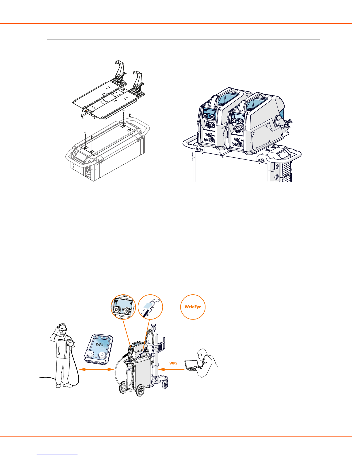
X8 MIG WELDER 2.5 Operation
Double Wire Feeder Rotating Plate
The double wire feeder rotating plate allows the use of two wire feeders on one power source.
2.5 Operation
Follow these operating instructions carefully to have full advantage of your X8 MIG Welder and to
minimize the risk of malfunctions.
2.5.1 X8 MIG Welder control devices
Welding with X8 MIG Welder can be controlled through three different control panels, which offer
slightly different features for adjusting the welding parameters.
The actual features vary according to the functions and usability of the control panel.
OPERATING MANUAL | EN 93
©
KEMPPI 2017 | 1817
Page 94
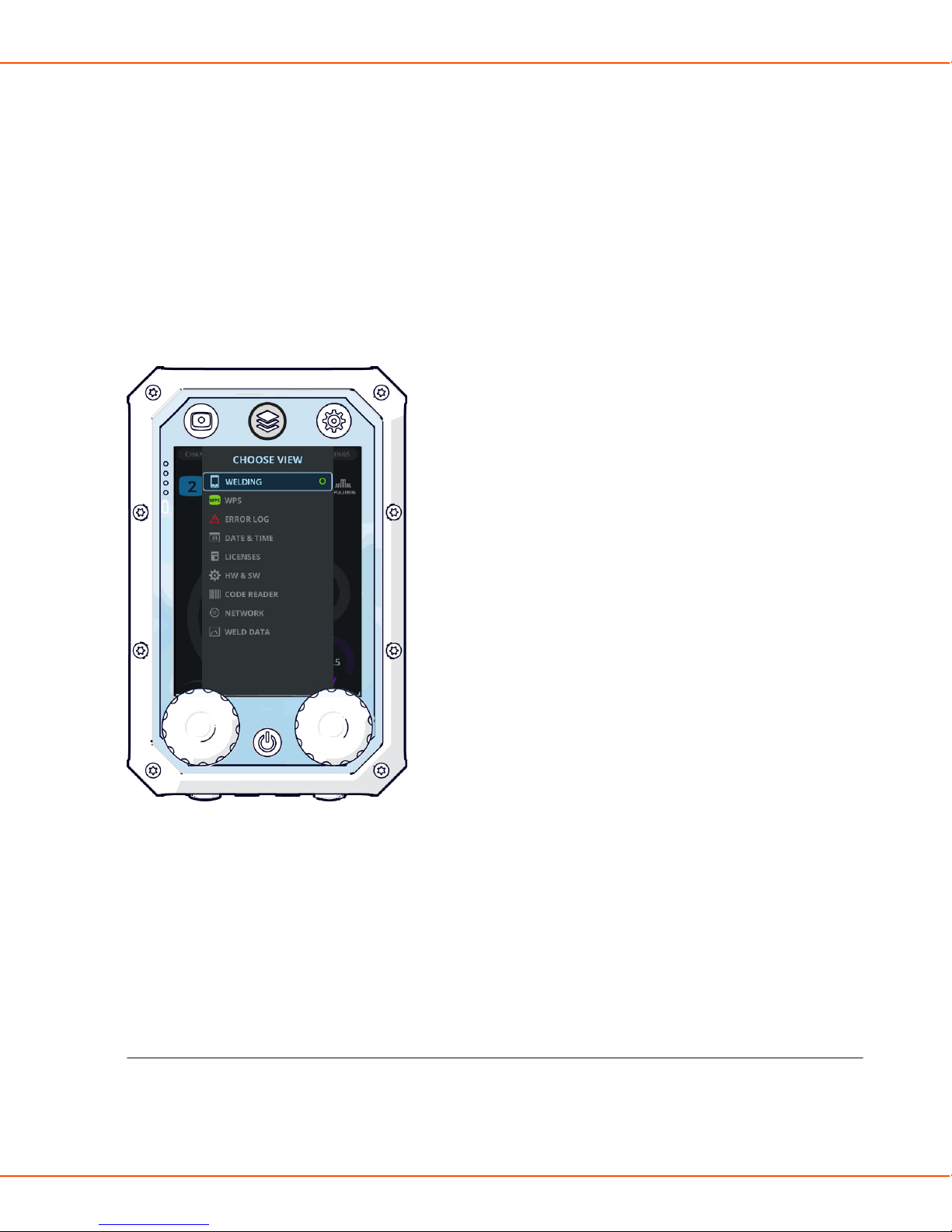
X8 MIG WELDER 2.5 Operation
2.5.1.1 Control Pad
Control Pad is a window to X8 MIG Welder: Control Pad shows you all the settings and licenses
installed in the welding system.
You can adjust the welding parameters and their values remotely with the one-knob navigation,
and connect Control Pad to any X8 MIG Welder nearby.
Navigation
Above the display, Control Pad has three view buttons. Press these buttons to change the view on
Control Pad's display. Press the Menu button twice to open the View menu.
Use the knobs under the display to move in the display and to adjust the values. When there is a
green light in the center of the knob, the knob also functions as a push button.
Figure 6: The View menu
In the Welding view, adjust the welding power with the left knob and the fine tuning with the
right knob. In most welding processes, this secondary parameter is voltage.
In all other views, move up and down in the menus with the right knob. Press the green button in
the center of the knob to open an item.
If you need to perform a reversing action, such as Cancel or Default, press the green button to
accept.
Header and footer
Control Pad's header displays the serial number of the welding machine, the selected wire feeder,
and the name of the user:
OPERATING MANUAL | EN 94
©
KEMPPI 2017 | 1817
Page 95
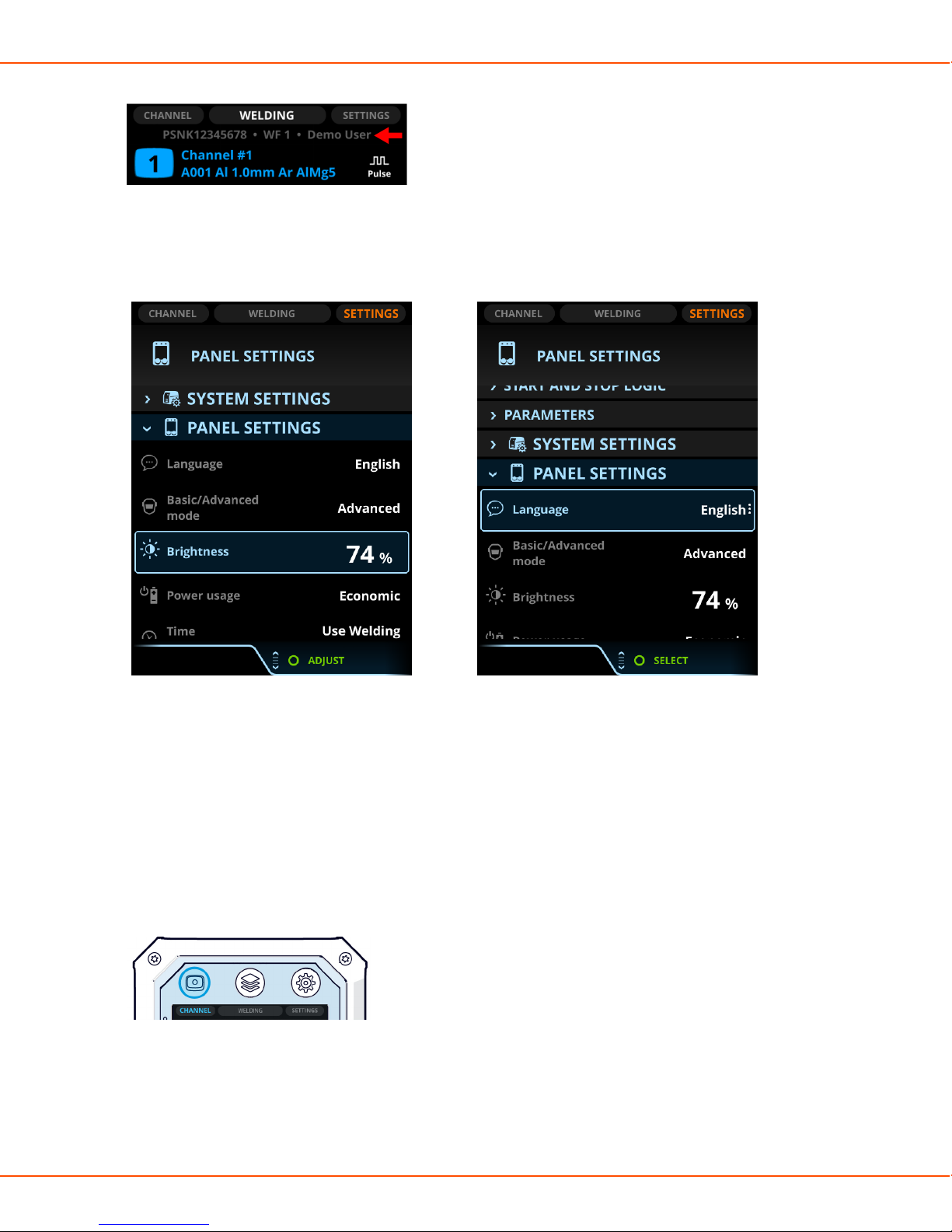
X8 MIG WELDER 2.5 Operation
There is an instruction on the footer above the knob, when the knob has a specific function. A
green circle in the footer prompts the push of the button on the control knob. The adjustable
parameter or value in focus is highlighted with orange.
Figure 7: Control Pad display with the Adjust
footer
Figure 8: Control Pad display with the Select footer
If the selection of the toggle button comes into effect right away, the footer command is Close. If
the change comes into effect after pressing the green button, the footer command is OK.
Control Pad views
There are three main views on Control Pad display: Channel (memory channels), Welding, and
Settings. Toggle between the views with the view buttons. The View menu inside Welding
opens, when you press the middle view button again in the Welding view.
Figure 9: The Channel view button
OPERATING MANUAL | EN 95
©
KEMPPI 2017 | 1817
Page 96
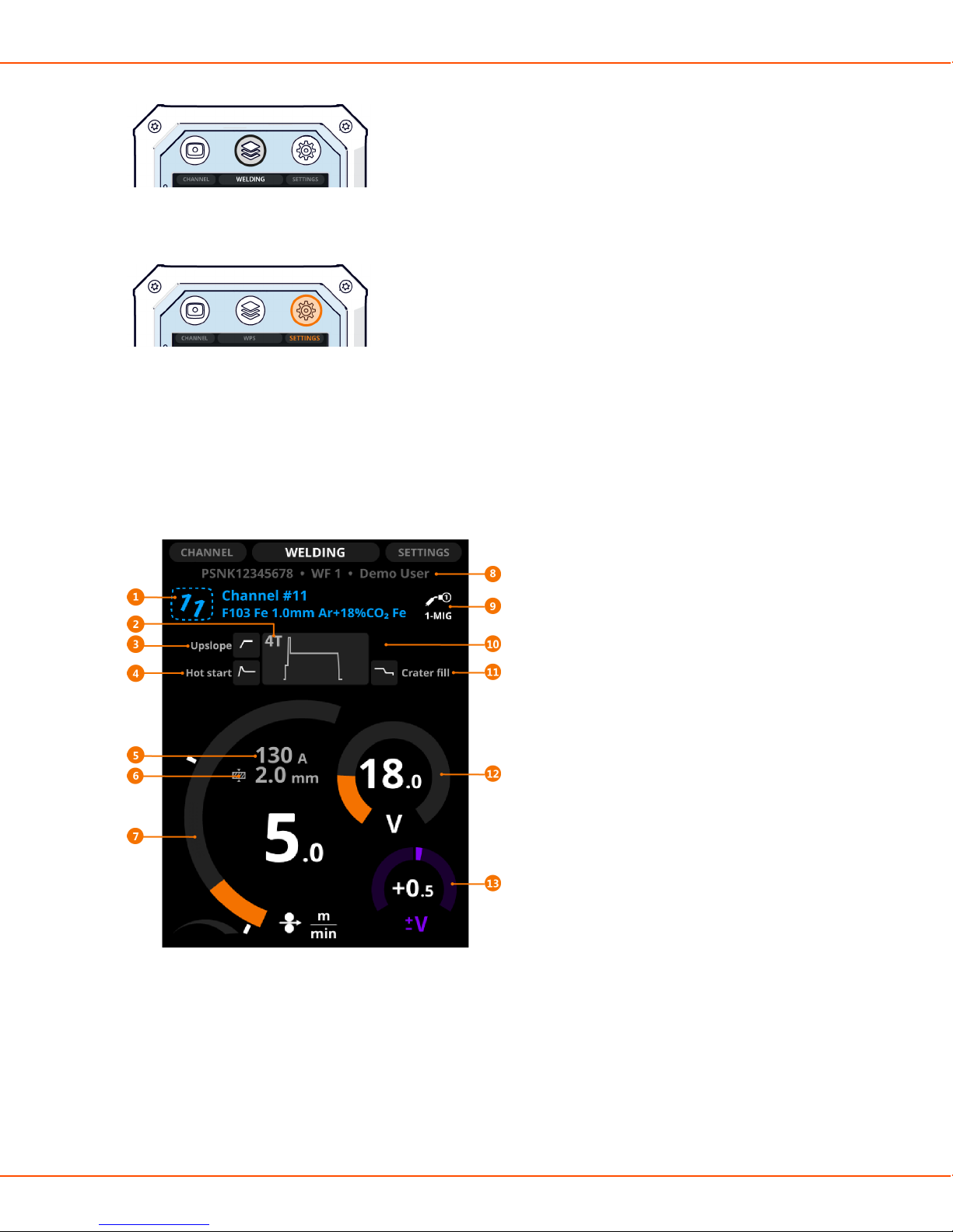
X8 MIG WELDER 2.5 Operation
Figure 10: The Welding view button
Figure 11: The Settings view button
Welding view
In the Welding view, you can:
• See an overview of the settings of the selected welding program
• Adjust the main parameters (welding power and fine tuning)
Depending on the selected welding process, function and program, some or all of the following
information is shown:
1. Memory channel, its number and the welding program
The first row shows the memory channel's name.
The second row shows the welding program's name, which consists of the filler wire material
and diameter and the shielding gas.
OPERATING MANUAL | EN 96
©
KEMPPI 2017 | 1817
Page 97

X8 MIG WELDER 2.5 Operation
If you have modified the welding settings, the channel number tilts to the right. To save
changes, press and hold the Channel button until the number returns to its normal position.
2. Operation mode of the welding gun (trigger logic)
3. Upslope
The selected start and stop logics.
4. Hot start
The selected start and stop logics.
5. Estimated welding current
6. Estimated plate material thickness
7. Wire feed speed
8. Serial number of the power source, wire feeder's number (1 or 2) and user name
9. Welding process
10. WP Switch
The WP Switch symbol is displayed in this field when WP Switch trigger logic is
in use. For more information, see Trigger logic functions on page 152.
11. Crater fill
The selected start and stop logics.
12. Voltage
13. Voltage/Fine tuning
Adjust the welding power with the left control knob.
Fine tune the secondary welding parameter with the right control knob. The adjustable secondary
parameter varies according to the welding process and function.
The welding power graph shows with grey raster pattern the area, where the selected values
result in globular transfer.
OPERATING MANUAL | EN 97
©
KEMPPI 2017 | 1817
Page 98

X8 MIG WELDER 2.5 Operation
Figure 12: Raster pattern in the wire feed arc
In DPulse and WP Switch, you can adjust two value sets: the first level and the second power level.
Press the left green button to toggle between them. Adjust the values with the control knobs. The
other power level is shown with gray line on the wire feed speed diagram.
Figure 13: Toggling DPulse (1) Figure 14: Toggling DPulse (2)
You can specify the minimum and maximum values of the wire feed speed. They are displayed as
white stoppers beside the wire feed speed diagram.
OPERATING MANUAL | EN 98
©
KEMPPI 2017 | 1817
Page 99

X8 MIG WELDER 2.5 Operation
Figure 15: The minimum and maximum stoppers
The value range of the welding power and voltage graphs specified by the Welding Procedure
Specification (WPS) are displayed with a green arc between the stoppers. The stoppers are
by default at the top and bottom of the specified WPS area, but you can adjust them to your
preferences: to narrow the area or to weld outside the specified area.
Figure 16: The minimum and maximum stoppers for WPS
If you adjust the wire feed speed or voltage to a level outside the WPS range, the parameter
graph turns red and a warning symbol appears on the display.
OPERATING MANUAL | EN 99
©
KEMPPI 2017 | 1817
Page 100

X8 MIG WELDER 2.5 Operation
Note:
If you have installed WeldEye, it saves the data as unsuitable use, even if the welding job
requires such values.
Figure 17: Values outside the range specified by WPS
Settings view
Settings displays all the welding parameters and other settings of the selected program. The
contents under the titles are collapsed by default. Press the green button to expand the columns.
There are two modes, Basic and Advanced. This section describes the Settings view in the
Advanced mode.
OPERATING MANUAL | EN 100
©
KEMPPI 2017 | 1817
 Loading...