

Page 1

1920840
1814
A7 MIG WelderX3 MIG Welder
EN
OPERATING MANUAL
Page 2

2
X3 MIG Welder© Kemppi Oy 2018 1814
OPERATING MANUAL
CONTENTS
1. Read rst .................................................................................................3
1.1 General ......................................................................................................3
1.2 About X3 MIG Welder product series .......................................................3
2. X3 MIG Welder structure ..................................................................4
2.1 System introduction ..................................................................................4
2.2 X3 Power Source........................................................................................4
2.3 X3 Wire Feeder ...........................................................................................5
3. Installation .............................................................................................5
3.1 Before use ..................................................................................................5
3.2 Positioning of the machine .......................................................................5
3.3 Distribution network .................................................................................6
3.4 Connecting cables .....................................................................................6
3.4.1 Mains connection ...................................................................................6
3.4.2 Wire feeder connection ...........................................................................7
3.4.3 Earth return cable connection ...................................................................7
3.5 Optional accessories .................................................................................8
3.5.1 Wheel sets.............................................................................................8
3.5.2 Undercarriage ........................................................................................8
3.5.3 Wire feeder mounting plate ......................................................................8
3.5.4 Gas heater .............................................................................................8
4. Operation ...............................................................................................9
4.1 Loading the ller wire ...............................................................................9
4.1.1 Mounting and locking the wire spool .........................................................9
4.1.2 Adjusting the spool brake ........................................................................9
4.1.3 Adjusting the pressure arms .....................................................................9
4.1.4 Feeding the ller wire ............................................................................10
4.1.5 Wire feed mechanism DuraTorque 400 .....................................................10
4.2 Controlling the welding system..............................................................12
4.2.1 Setup panel .........................................................................................12
4.2.2 Starting the power source ......................................................................12
4.2.3 LCD display .........................................................................................12
4.2.4 LED indicators ......................................................................................12
4.2.5 Settings menu parameters .....................................................................13
4.2.6 Wire feeder control panel .......................................................................14
4.3 Selecting shielding gas ...........................................................................14
4.4 Gas test ....................................................................................................14
4.5 Trigger logic and Crater ll function .......................................................14
4.6 Calibrating wire feed speed ....................................................................16
5. Troubleshooting ................................................................................17
6. Maintenance .......................................................................................17
6.1 Regular maintenance ..............................................................................17
6.2 Disposal of the machine .........................................................................17
7. Technical data ....................................................................................18
8. Ordering codes ..................................................................................20
Page 3

3
X3 MIG Welder© Kemppi Oy 2018 1814
OPERATING MANUAL
1. READ FIRST
1.1 General
Congratulations on choosing the X3 MIG Welder series
power source. Used correctly, Kemppi products can signicantly increase the productivity of your welding, and
provide years of economical service.
This operating manual contains important information
on the use, maintenance and safety of your Kemppi
product. The technical specications of the device can
be found at the end of the manual.
Please read the manual carefully before using the equipment for the rst time. For your own safety and that of
your working environment, pay particular attention to
the safety instructions in the manual.
For more information on Kemppi products, contact
Kemppi Oy, consult an authorised Kemppi dealer, or visit
the Kemppi web site at www.kemppi.com.
The specications presented in this manual are subject to
change without prior notice.
Important notes
Items in the manual that require particular attention in
order to minimize damage and harm are indicated by the
symbols below. Read these sections carefully and follow
their instructions.
Note: Gives the user a useful piece of information.
Caution: Describes a situation that may result in dam-
age to the equipment or system.
Warning: Describes a potentially dangerous situation.
If not avoided, it will result in personal damage or fatal
injury.
Disclaimer
While every eort has been made to ensure that the information contained in this guide is accurate and complete,
no liability can be accepted for any errors or omissions.
Kemppi reserves the right to change the specication of
the product described at any time without prior notice.
Do not copy, record, reproduce or transmit the contents
of this guide without prior permission from Kemppi.
1.2 About X3 MIG Welder product series
X3 MIG Welder is a set of inverter-based welding equipment intended for professional use in industrial MIG/MAG
welding applications. It can be connected to a 3-phase
mains power supply.
The X3 MIG Welder contains either a 400- or 500-ampere
X3 Power Source and the X3 Wire Feeder 300 unit for wire
feeding.
The system is equipped with gas type selection buttons.
It automatically presets the welding dynamic characteristic according to your gas selection choice.
Enjoy welding with your Kemppi product!
Page 4

4
X3 MIG Welder© Kemppi Oy 2018 1814
OPERATING MANUAL
2. X3 MIG WELDER STRUCTURE
2.1 System introduction
• X3 Power Source
• X3 Wire Feeder 300: The wire feeder can be
installed as stand-alone, or it can be mounted on
top of the power source with an optional X3 Wire
Feeder Mounting Plate.
• X3 Wheel Set / X3 Four Wheel Set (optional). The
power source can be equipped with large rear
wheels and/or a set of turning front wheels.
• P20 undercarriage (optional)
• Power supply for external gas heater
2.2 X3 Power Source
3
1
4 5 6
2
FRONT
1. ON/OFF switch
2. LCD display
3. Fan grill
4. Earth return cable connector ( – )
5. Control cable connection
6. Wire feeder cable connector ( + )
10
8
9
7
BACK
7. Mains cable
8. Power source fuse, 6.3 A
9. Shielding gas heater fuse, 2 A
10. Connector for shielding gas heater
Page 5

5
X3 MIG Welder© Kemppi Oy 2018 1814
OPERATING MANUAL
2.3 X3 Wire Feeder
1
2
3
4
5
1. Control panel
2. Welding gun connection
3. Shielding gas connection
4. Control cable connection
5. Welding current cable connection
3. INSTALLATION
3.1 Before use
Always make sure before use that the products have not
been damaged during transportation.
Check also that you have received the components you
ordered and the instruction manuals needed. Product
packaging material is recyclable.
When moving the welding machine, always lift it from
the handle, never pull it from the welding gun or other
cables.
Operating environment
This machine is suitable for both indoor and outdoor
use. Always make sure that the air ow in the machine is
unrestricted. The recommended operating temperature
range is –20…+40 °C.
Please read also the Safety Instructions concerning the
operating environment.
3.2 Positioning of the machine
Place the machine on a sturdy, level surface that is dry
and does not allow dust or other impurities to enter the
machines cooling air ow. Preferably site the machine to
a suitable carriage unit so it is above oor level.
Notes for positioning the machine
• The surface inclination may not exceed
15 degrees.
< 15°
• Ensure the free circulation of the cooling air.
There must be at least 20 cm of free space in
front of and behind the machine for cooling air
circulation.
• Protect the machine against heavy rain and
direct sunshine.
The machine is not allowed to be operated in the rain
as the protection class of the machine, IP23S, allows
preserving and storing outside only.
Never aim the spray of sparks from a grinding ma-
chine toward the equipment.
Page 6

6
X3 MIG Welder© Kemppi Oy 2018 1814
OPERATING MANUAL
3.3 Distribution network
All regular electrical devices without special circuits generate harmonic currents into distribution network. High
rates of harmonic current may cause losses and disturbance to some equipment.
X3 Power Source 400 / 400 AU
This equipment complies with IEC 61000-3-12 provided
that the short-circuit power Ssc is greater than or equal to
4.7 MVA at the interface point between the user’s supply
and the public supply network. It is the responsibility
of the installer or user of the equipment to ensure, by
consultation with the distribution network operator
if necessary, that the equipment is connected only to
a supply with a short-circuit power Ssc greater than or
equal to 4.7 MVA.
X3 Power Source 500
This equipment complies with IEC 61000-3-12 provided
that the short-circuit power Ssc is greater than or equal to
5.2 MVA at the interface point between the user’s supply
and the public supply network. It is the responsibility
of the installer or user of the equipment to ensure, by
consultation with the distribution network operator
if necessary, that the equipment is connected only to
a supply with a short-circuit power Ssc greater than or
equal to 5.2 MVA.
3.4 Connecting cables
3.4.1 Mains connection
The X3 Power Source is connected to a 380 – 440 V threephase network. On the back side of the machine, there
is a mains cable that does not hava a plug. Before use,
check the mains cable and install a suitable mains plug.
If the cable does not comply with the local electrical
regulations, replace it with a compliant cable.
L1 L2 L3
Replacement of the mains cable:
1. Unscrew the mounting screws on the cover plate
of the machine, and remove the case by lifting it.
2. Disconnect the phase leads from connectors L1,
L2, and L3, and disconnect the protective earth
lead.
3. Pass the cable to the machine through the mains
cable inlet ring at the rear of the machine, and
secure the cable with a cable clamp.
4. Connect the cable’s phase leads to connectors L1,
L2, and L3.
5. Connect the yellow-green protective earth lead to
its connector
6. Screw the cover plate back in place.
The mains cable or wall plug may be installed or replaced only by an electrical contractor or installer authorised to perform such operations.
Page 7

7
X3 MIG Welder© Kemppi Oy 2018 1814
OPERATING MANUAL
3.4.2 Wire feeder connection
On the front side of the power source, there are connectors for the interconnection cable
and the control cable for connecting the power source to the wire feeder.
To connect the wire feeder to the power source, complete the following steps:
1 2
3
1. Attach the wire feeder’s welding current cable to the plus (+) connector of the
power source. Hand tighten the connector with a clockwise push and twist action to
lock.
2. Attach the wire feeder control cable plug to the control socket of the power source.
3. Connect the shielding gas hose to the gas bottle or to the shielding gas distribution
system.
Normally the wire feeder should be connected to the plus (+) pole. However, with
some ller wires and shielding gases, you should connect it to the minus (-) pole, and the
earth return cable to the plus pole.
3.4.3 Earth return cable connection
Attach the earth return cable to the minus (–) connector. Hand tighten the connector
with a clockwise push and twist action to lock.
Attach the other end of the earth return cable to the workpiece before welding.
When attaching the earth return clamp to the work piece, remember to clean the
work piece surface so as to achieve safe and undisturbed operation.
Page 8

8
X3 MIG Welder© Kemppi Oy 2018 1814
OPERATING MANUAL
3.5 Optional accessories
3.5.1 Wheel sets
The X3 Power Source can be tted with wheels for easy
movement of the unit.
There are two dierent wheel sets available, one with
big rear wheels only and another with big rear wheels
and turning front wheels. Installation instructions are
delivered with the wheel set package.
x 4
x 4
3.5.2 Undercarriage
To enable easy movement of the unit, the power source
can be mounted on the P20 undercarriage. Installation
instructions are delivered with the undercarriage
package.
3.5.3 Wire feeder mounting plate
If you are using wheels or undercarriage, you can attach
the wire feeder on top of the power source using the X3
Wire Feeder Mounting Plate to create a compact welding
unit that is easy to move around.
To mount the wire feeder on top of the power source,
follow the instructions delivered with the mounting plate.
1 2
x 5
x 4
3.5.4 Gas heater
When using CO₂ shielding gas, a 110 V gas heater can be
connected to the power supply located at the back of the
X3 MIG Welder power source.
Page 9
9
X3 MIG Welder© Kemppi Oy 2018 1814
OPERATING MANUAL
4. OPERATION
4.1 Loading the ller wire
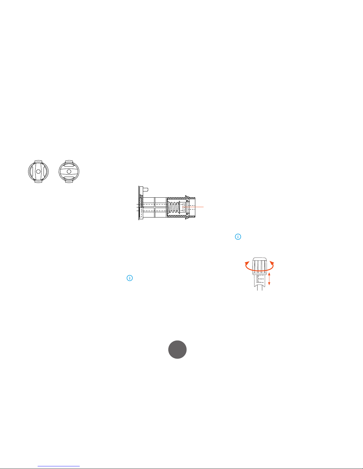
4.1.1 Mounting and locking the wire spool
LOCKED OPEN
• Release locking nails of wire spool hub by
turning locking knob a quarter round.
• Mount the spool at its place. Note rotating
direction of spool!
• Lock the spool with locking knob, locking nails
of hub remain to outside position and will lock
the spool.
4.1.2 Adjusting the spool brake
Brake force is adjusted through the hole behind the
locking clip. Remove the locking clip by hand, and adjust
the tension and pressure to the friction pads mounted
inside with a screw driver. See diagram and location A.
A
The load applied varies depending on the size and weight
of the ller wire and spool, but also on the wire feed
speed. The heavier the wire spool and the faster the feed
speed, the greater the need to increase the braking load.
Adjust the pressure, secure the locking clip, set the wire
feed speed and check that the braking force is enough
to ensure the ller wire does not spill from the spool on
overrun.
Too much or unnecessary loads can impact welding
quality, load and wear to the wire feed system.
4.1.3 Adjusting the pressure arms
Adjust the drive pressure to the ller wire with the thumb
screws mounted over the pressure arms. Notice the graduated scales indicating load. The load applied should be
sucient to overcome a light braking force applied by
hand to the ller wire, as it exits the welding gun contact
tip.
For smaller diameter and soft ller wires, less feed pressure is required. It should be possible to apply a light
breaking force to the ller wire by hand, as it exits the gun
contact tip. But slightly more wire ow restriction should
render the drives rolls to slip slightly over the ller wire
without deforming the wire.
Excessive pressure causes attening of the ller wire
and damage to coated or cored ller wires. It also causes
undue wear of the feed rolls and increases gearbox load, so
reducing service life.
Page 10

10
X3 MIG Welder© Kemppi Oy 2018 1814
OPERATING MANUAL
4.1.4 Feeding the filler wire
Ensure that the groove of the feed roll matches the diameter of ller wire used. Release
the wire end from the spool and cut o any deformed section. Be careful the wire does
not spill from the spool sides
1. Connect the welding gun and tighten the collar.
2. Straighten about 20 cm of ller wire and ensure the tip has no sharp edges. File if
necessary, as a sharp wire edge may damage the wire gun liner – particularly softer
plastic liners.
3. Present the ller wire tip to the back of the wire feed rolls and press the wire inch
switch on the wire feed panel. Feed the wire to the gun contact tip and prepare to
weld.
4. Press the Wire Inch button and allow the ller wire to feed through the gun cable to
the contact tip.
4.1.5 Wire feed mechanism DuraTorque 400
Wire guide tubes
ø mm colour outlet tube middle tube inlet tube
Ss, Al,
(Fe, Mc, Fc)
plastic
0.6 SP007437 SP007429 SP007293
0.8 – 0.9 SP007438 SP007430 SP007294
1.0 SP007439 SP007431 SP007295
1.2 SP007440 SP007432 SP007296
1.4 SP007441 SP007433 SP007297
1.6 SP007442 SP007434 SP007298
2.0 SP007443 SP007435 SP007299
2.4 SP007444 SP007436 SP007300
Fe, Mc, Fc
metal
0.8 – 0.9 SP007454 SP007465 SP007536
1.0 SP007455 SP007466 SP007537
1.2 SP007456 SP007467 SP007538
1.4 – 1.6 SP007458 SP007469 SP007539
2.0 SP007459 SP007470 SP007540
2.4 SP007460 SP007471 SP007541
Page 11

11
X3 MIG Welder© Kemppi Oy 2018 1814
OPERATING MANUAL
Wire feed rolls, plastic
ø mm colour lower upper
Fe, Ss,
(Al, Mc, Fc)
V-groove
0.6 W001045 W001046
0.8 – 0.9 W001047 W001048
1.0 W000675 W000676
1.2 W000960 W000961
1.4 W001049 W001050
1.6 W001051 W001052
2.0 W001053 W001054
2.4 W001055 W001056
Fc, Mc, (Fe)
V-groove, knurled
1.0 W001057 W001058
1.2 W001059 W001060
1.4 – 1.6 W001061 W001062
2.0 W001063 W001064
2.4 black W001065 W001066
Al, (Fc, Mc, Ss, Fe)
U-groove
1.0 W001067 W001068
1.2 W001069 W001070
1.6 W001071 W001072
Wire feed rolls, metal
ø mm lower upper
Fe, Ss,
(Al, Mc, Fc)
V-groove
0.8 – 0.9 W006074 W006075
1.0 W006076 W006077
1.2 W004754 W004753
1.4 W006078 W006079
Fc, Mc, (Fe)
V-groove, knurled
1.0 W006080 W006081
1.2 W006082 W006083
1.4 – 1.6 W006084 W006085
2.0 W006086 W006087
Al, (Fc, Mc, Ss, Fe)
U-groove
1.0 W006088 W006089
1.2 W006090 W006091
1.6 W006092 W006093
Mount the lower feed roll, ensuring that the pin on the shaft ts in the cut on the
feed roll.
Page 12

12
X3 MIG Welder© Kemppi Oy 2018 1814
OPERATING MANUAL
4.2 Controlling the welding system
4.2.1 Setup panel
Use the Setup panel on the X3 Power Source to change
the settings of your welding system.
1
Gas test button
Press to test the shielding gas ow.
X3
MIG
Welder
1
4
5
2
3
6
2
Gas select button
Press to select either CO₂ or mixed
shielding gas (MAG).
3
Press to select between 2T and 4T gun
trigger modes.
4
Crater ll button
Press to select the Crater ll mode ON
or OFF.
5
Wire feed speed adjustment knob
Turn to set the wire feed speed value for
the Crater ll mode.
6
Voltage adjustment knob
Turn to set the welding voltage value for
the Crater ll mode.
4.2.2 Starting the power source
To start the power source, turn the main switch to position ‘I’. Initially, the rmware version number is displayed
in the LCD display. After that, the rmware number is replaced with the parameter display, and the machine is
ready for setup.
4.2.3 LCD display
The X3 MIG Power Source is equipped with an LCD display. Welding parameter settings
are made through the X3 Wire Feeder control panel for wire feed speed (A) and voltage
(V). During welding the display always shows the welding current (A) used.
The average welding values remain on display for 10 seconds after you stop welding.
The upper part of the display shows wire feed speed, the selected welding voltage and
gas type selection. The lower part of display shows the Crater ll values.
4.2.4 LED indicators
There are two LED indicator lights on the top of the control panel.
1 2
1. The ON light indicates that the power source is turned on.
2. The second light indicates that the machine is over heated.
The machine stops automatically when it reaches its maximum operating temperature. If the heat indicator led is on, the machine has exceeded its normal maximum operating temperature. Stop welding and wait until the led turns o. The machine is then ready
for welding to continue.
Page 13

13
X3 MIG Welder© Kemppi Oy 2018 1814
OPERATING MANUAL
4.2.5 Settings menu parameters
In Settings menu you can enable or disable welding parameters and adjust their
values.
Parameter Values
CrE Creep start 1 = On / 0 = O
PrE Pre gas 1 = On / 0 = O
Pre gas Pre gas 1 = On / 0 = O
Pos Post gas 1 = On / 0 = O
Ign Hard ignition
Makes the arc ignition stronger by increasing welding
voltage at the start of the weld.
1 = On / 0 = O
HSt Hot stop
Enhances the end of the weld in certain applications
by delaying the arc extinction and raising the welding
voltage at the end of welding. Especially useful in tack
welding.
1 = On / 0 = O
BUr Burn back time
Time that torch will be live after welding has stopped
to prevent ller wire from sticking to the work piece.
(-01 = Use defaults from welding program.
Integer (ms):
-01…999
LOC Panel Lock
Locks the setup panel and prevents welding
parameters from being changed.
‘LOC’ ashes on the screen on attempt to change
parameters. Setting is remembered on the next
startup.
1 = enabled with
code 769
0 =disabled with
code 769
FAC Fact ory re set
Resets the user interface and special settings to
factory defaults on menu exit.
1 = On / 0 = O
To enable or disable welding parameters
1. Open Settings menu by pressing Crater ll and Gas test buttons
simultaneously.
2. Use Gas select and 2T/4T buttons to navigate to the desired parameter.
3. Press Crater ll button to toggle the the state of the parameter (On or O ).
4. Exit the menu and save the changes by pressing Crater ll and Gas test buttons
simultaneously.
To set values for Burn back time or Panel lock code
1. Open Settings menu by pressing Crater ll and Gas test buttons
simultaneously.
2. Use Gas select and 2T/4T buttons to navigate to BUr or LOC menu item.
3. Press Crater ll button to activate a single digit so that it starts to blink.
4. Use Gas select and 2T/4T buttons to increase and decrease the value of the
digit.
5. Press Crater ll to activate another digit.
6. Press Crater ll and Gas test simultaneously to exit the menu and save the
changes.
To use carbon arc gouging
+
Press Crater ll and 2T/4T to enter the gouging
mode.
+
Adjust the voltage with Gas select and 2T/4T
buttons.
Activate another digit by pressing Crater ll
button.
+
Exit gouging mode by pressing Crater ll and
2T/4T simultaneously.
Output terminals are live in carbon arc gouging mode.
Page 14

14
X3 MIG Welder© Kemppi Oy 2018 1814
OPERATING MANUAL
4.2.6 Wire feeder control panel
Use the Control panel on the X3 Wire Feeder to adjust the
welding parameters.
1
2
3
1. Wire feed speed
Turn to adjust the wire feed speed. The amperage
level is automatically changed to match the wire
feed speed setting. See the value tables at the end of
this manual.
2. Welding voltage
Turn to adjust the welding voltage level. The voltage
level determines the arc length.
3. Wire inch
Press to feed the ller wire into the welding gun.
4.3 Selecting shielding gas
Press the shielding gas selection button to set the shielding gas type to either CO₂ or mixed gas according to the
gas you are using.
Select CO₂ if you are using carbon dioxide. Select Ar + CO₂
(MAG) if you are using mixed gas.
X3 MIG Welder has a factory set Pre gas time of 0.2 s
and a Post gas time of between 2 – 4 s, depending on the
welding power settings.
4.4 Gas test
To test the shielding gas ow, press the gas test button
once. The shielding gas starts to ow and stops automatically after 20 seconds.
To interrupt the gas test, press the button again.
4.5 Trigger logic and Crater ll function
The purpose of Crater ll is to facilitate controlled nishing
of welding and to reduce the welding faults caused by
the nal crater. The Crater ll parameters can be specied
in the Setup panel.
2T mode
MIG welding with 2T mode of the gun trigger.
• Push the trigger – welding starts after preset Pre
gas time.
• Release the trigger – welding ends. Post gas
ows for preset time.
1. 2.
1. Pre gas time
2. Post gas time
Page 15

15
X3 MIG Welder© Kemppi Oy 2018 1814
OPERATING MANUAL
2T mode and Crater ll function
• Push the trigger – welding starts after preset Pre
gas time.
• Release the trigger – values drop to preset Crater
ll level and welding ends after preset time. Post
gas ows for preset time.
1. 2. 3.
1. Pre gas time
2. Crater ll time
3. Post gas time
4T mode
MIG welding with 4T mode of the gun trigger.
• Trigger pushed down – ow of shielding gas
starts.
• Trigger released – welding starts.
• Trigger pushed down – welding ends and shielding gas ow continues.
• Trigger released – ow of shielding gas ends.
Post gas time at least preset minimum.
1. 2.
1. Pre gas time
2. Post gas time
4T mode and Crater ll function
• Trigger pushed down – ow of shielding gas
starts.
• Trigger released – welding starts.
• Trigger pushed down – welding values change
to Crater ll level.
• Trigger released – welding ends. Post gas time
ows for preset time.
1. 2. 3.
1. Pre gas time
2. Crater ll time
3. Post gas time
Page 16
16
X3 MIG Welder© Kemppi Oy 2018 1814
OPERATING MANUAL
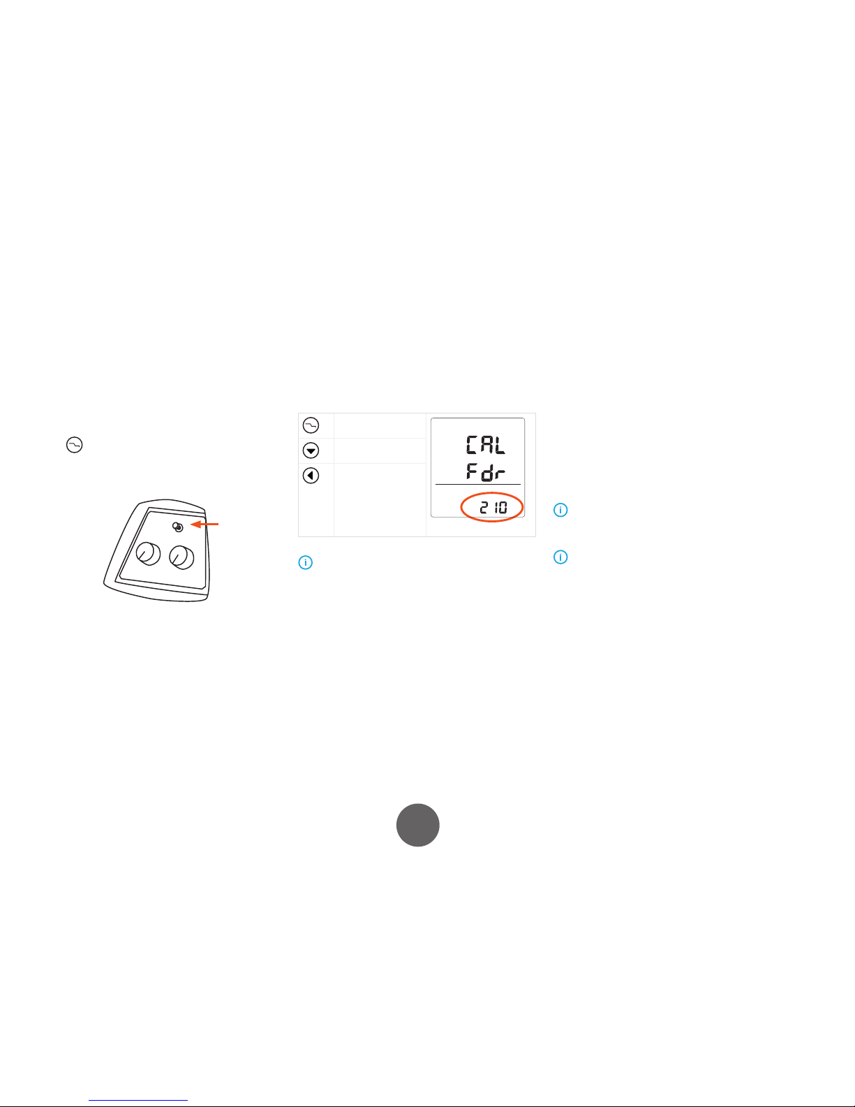
4.6 Calibrating wire feed speed
To ensure that the pre-sets and meter displays work as
planned, you must calibrate the wire feed speed on your
X3 MIG Welder.
To calibrate the wire feed speed
1. At the power source control panel, press the Crater
ll button for 3 seconds.
2. Cut the ller wire at the contact tip.
3. Press Wire Inch button at the wire feeder. Wire feed
starts and continues for 12 seconds.
4. When wire feed stops, cut the wire at the contact tip
and measure the length of the fed wire in mm.
5. At the power source control panel, enter the length
of the wire using the following buttons.
Toggle between the
digits of the number
Increase the digit by
one
Decrease the digit
by one
If you enter a value that does not t in, the machine
forces the value within the acceptable limits. .
6. Press Wire Inch button again. Wire feed starts and
continues for 2 seconds.
7. When wire feed stops, cut the wire and measure its
length.
8. At the power source control panel, enter the length
of the wire.
9. Press Wire Inch button.
To skip the calibration, do one of the following:
• Exit the calibration mode by pressing Crater ll
button for 3 seconds.
• Exit the calibration mode by leaving the machine
idle for 5 minutes.
• Turn o the machine before the step 9 to exit the
calibration mode and keep the old calibration
values.
The X3 Wire Feeder 300 must always be calibrated
before the rst use and if combined with a dierent X3
Power Source.
Check the wire feeder’s calibration regularly. Correctly
calibrated wire feeder ensures quality welds.
Page 17
17
X3 MIG Welder© Kemppi Oy 2018 1814
OPERATING MANUAL
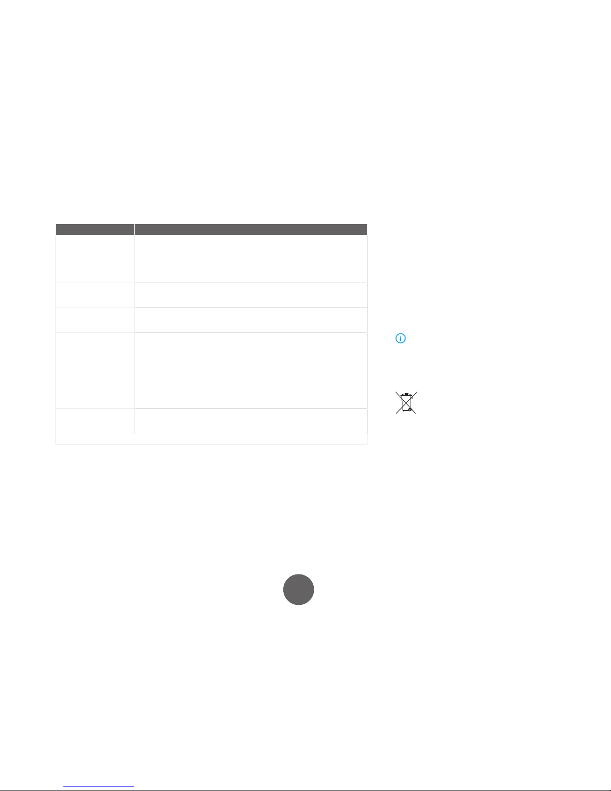
5. TROUBLESHOOTING
Problem Cause
The machine stops
working. Overheating
indicator is lit, and Err 4 is
displayed.
The machine has overheated.
• Ensure that cooling air has unrestricted ow.
• The machine’s duty cycle has been exceeded.
If no other damage is caused, the fan starts working and the machine recovers
within a couple of minutes.
If the problem persists, please contact Kemppi service representative.
Machine stops working.
Err 2 or Err 3 is displayed.
The mains voltage is either too low (Err 2) or too high (Err 3). *
The machine recovers automatically, when the mains voltage is in the
recommended range (342 – 484 V).
Machine stops working.
Err 43 is displayed.
The wire feeder motor is overloaded.
Check that you are using the right wire type and that the wire feed route is
unobstructed.
Poor welding result Several factors aect the welding quality.
• Check wire feed calibration.
• Check that the ear th return clamp is properly attached, the point of contact is
clean and that the cable and its connectors are intact.
• Check the voltage and wire speed settings on the control panel are correct for the
given wire size and type.
• Check that the shielding gas ow rate at the gun nozzle is correct.
• Check that the shielding gas is suitable for the ller wire used.
• Check that the wire feed is constant, and adjust if necessary.
• Check that the mains voltage is not too irregular.
Main switch indicator does
not switch on
The machine has no mains voltage
• Check the mains fuses
• Check the mains cable and the wall plug
* Contact Kemppi service in case of Err 2 and Err 3 without mains voltage cause.
6. MAINTENANCE
6.1 Regular maintenance
Check regularly the electrical connections of the machine. Clean any oxidised connections, and tighten the
loosened cable connections.
Let authorised Kemppi service workshop make periodic
service to your machine. Appropriate use and regular
service guarantee trouble-free use of the machine. This
allows you to avoid interruptions and increase the productivity of the machine.
NOTE! Remember that the machine may be repaired
only by an electrical contractor or installer authorised to
perform such operations.
6.2 Disposal of the machine
Do not dispose of electrical equipment with normal
waste!
In observance of European Directive 2002/96/EC on
waste electrical and electronic equipment, and its implementation in accordance with national law, electrical
equipment that has reached the end of its life must be
collected separately and taken to an appropriate environmentally responsible recycling facility.
The owner of the equipment is obliged to deliver a decommissioned unit to a regional collection centre, per
the instructions of local authorities or a Kemppi representative. By applying this European Directive you will
improve the environment and human health.
Page 18

18
X3 MIG Welder© Kemppi Oy 2018 1814
OPERATING MANUAL
7. TECHNICAL DATA
X3 Power Source 400 / 400 AU 500
Mains connection voltage 3~, 50/60 Hz 380 – 440 V (–10 %…+10 %) 380 – 440 V (–10 %…+10 %)
Mains connection cable H07RN-F 4 G4 4 G4
Rated power at max. current 60 % ED 17.6 kVA 24.5 kVA
100 % ED 12.5 kVA 17 kVA
Supply current (maximum) I
1max
27 A 37 A
Supply current (eective) I
1e
19 A 29 A
Idle power Pi < 20 W < 20 W
Open circuit voltage U
av
52 – 57 V 57 – 62 V
No-load voltage, U
0
U
0
47 – 57 V 51 – 62 V
Fuse 25 A 35 A
Output 60 % ED 400 A / 34 V 500 A / 39.0 V
100 % ED 310 A / 29 V 390 A / 33.5 V
Welding current and voltage range 25 A/15 V – 400 A/38V 25 A/15 V – 500 A/43 V
Power factor at max current λ 0.88 0.90
Eciency at max current η 89 % 90 %
Operating temperature range –20...+40 °C –20...+40 °C
Storage temperature range –40...+60 °C –40...+60 °C
EMC class A A
Minimum short-circuit power SSC of supply network 4.7 MVA 5.2 MVA
Degree of protection IP23S IP23S
External dimensions L x W x H 629 x 230 x 414 mm 629 x 230 x 414 mm
Weight 32 kg 36 kg
Power supply for auxiliary devices U
aux
110 V/150 W 110 V/150 W
Standards IEC 60974-1
IEC 60974-10
IEC 60974-1
IEC 60974-10
The equipment complies with the requirements for the CE mark.
Page 19

19
X3 MIG Welder© Kemppi Oy 2018 1814
OPERATING MANUAL
X3 Wire Feeder 300
Operating voltage U
1
24 V
Gun connection Euro
Wire feed mechanism 4-roll
Filler wires Fe 0.6 – 1.6 mm
MC/FC 0.8 – 2.0 mm
Wire feed speed 0 – 25 m/min
Wire spool weight (max) 20 kg
Wire spool diameter (max) 300 mm
Operating temperature range –20...+40 °C
Storage temperature range –40...+60 °C
Degree of protection IP23S
External dimensions LxWxH 590 x 240 x 445 mm
Weight
Standards IEC 60974-5
IEC 60974-10
The equipment complies with the requirements for the CE mark.
Page 20

20
X3 MIG Welder© Kemppi Oy 2018 1814
OPERATING MANUAL
8. ORDERING CODES
X3 Power Source 400 X31004000
X3 Power Source 400 (AU) X31004000AU
X3 Power Source 500 X31005000
X3 Wire Feeder 300 X31003000
Welding guns
MMT 42 3.0 m 6254213MMT
MMT 42 4.5 m 6254214MMT
Interconnection cables
Interconnection cable 50-1.8-G 50 mm², 1.8 m, max. 300 A 6260508
Interconnection cable 70-1.8-GH 70 mm², 1.8 m 6260518
Interconnection cable 50-5-GH 50 mm², 5 m, max. 300 A 6260500
Interconnection cable 70-5-GH 70 mm², 5 m 6260501
Interconnection cable 50-10-GH 50 mm², 10 m, max. 300 A 6260513
Interconnection cable 70-10-GH 70 mm², 10 m 6260514
Interconnection cable 50-15-GH 50 mm², 15 m, max. 300 A 6260515
Interconnection cable 70-15-GH 70 mm², 15 m 6260516
Interconnection cable 70-20-GH 70 mm², 20 m 6260523
Interconnection cable 70-30-GH 70 mm², 30 m 6260633
Optional extensions
Extension cable 50-10-G 50 mm², 10 m, max. 300 A 6310510
Extension cable 50-15-G 50 mm², 15 m, max. 300 A 6310515
Extension cable 70-10-G 70 mm², 10 m 6310710
Extension cable 70-15-G 70 mm², 15 m 6310715
Earth return cables
Earth return cable, X3 MIG Welder 50 mm², 5 m, max. 300 A 6184511
Earth return cable, X3 MIG Welder 70 mm², 5 m 6184711
Accessories
X3 Wheel Set X37000001
X3 Four Wheel Set X37000002
X3 Wire Feeder mounting kit X37000003
P20 undercarriage 6185261
Fe 0.8 mm,
CO₂
N
mm
1 1.5 2 3 4 6 8 10
:
m/min
2.8 4.0 5.0 8.0 11.5 14.0 16.0 18.0
<
V
14.5 17 18 21 24 26.5 29 31.5
;
A
45 60 80 110 140 160 170 190
Fe 0.8 mm,
Ar + 15 –
25% CO₂
N
mm
1 1.5 2 3 4 6 8 10
:
m/min
2.8 4.0 5.0 8.0 11.5 14.0 16.0 18.0
<
V
14.5 16.5 17.5 20 22.5 25.3 28 30
;
A
50 70 90 120 150 160 180 200
Fe 1.0 mm,
CO₂
N
mm
1.2 1.5 2 3 4 6 8 10 12
:
m/min
2.2 3.0 4.3 6.0 7.3 9.7 12.0 15.0 18.0
<
V
16.5 18.0 19.5 22.2 24.0 27.3 31.0 35.0 38.0
;
A
60 85 120 150 170 200 230 260 285
Fe 1.0 mm,
Ar + 15 –
25% CO₂
N
mm
1.2 1.5 2 3 4 6 8 10 12
:
m/min
2.2 3.0 4.3 6.0 7.3 9.7 12.0 14.5 18.0
<
V
15.6 17.2 18.8 19.8 21.4 25.9 31.5 33.8 35.0
;
A
60 90 125 155 170 205 240 280 300
Fe 1.2 mm,
CO₂
N
mm
1 1.5 2 3 4 6 8 10 12 16 20
:
m/min
1 2 3 3 4.5 6 8.5 10 11 12.5 14
<
V
14.2 17 19 19.8 22 24 29.5 32 34 37 39
;
A
40 90 120 140 155 185 230 265 280 300 330
Fe 1.2 mm,
Ar + 15 –
25% CO₂
N
mm
1 1.5 2 3 4 6 8 10 12 16 20
:
m/min
1 2 3 3.6 4.5 6 8.5 10 11 12.5 14
<
V
13 15.7 17.5 18.8 20 21.5 27.5 31.5 32.8 35.5 37
;
A
50 95 125 145 165 200 245 285 300 330 345
Fe 1.6 mm,
CO₂
N
mm
1.2 1.5 2 3 4 6 8 10 12 16 20
:
m/min
1.0 1.3 1.8 2.8 3.0 3.5 5.0 5.5 6.0 7.0 13.0
<
V
16.0 17.5 19.6 21.5 22.5 24.5 30.0 31.5 33.0 36.0 40.0
;
A
75 95 130 185 195 215 275 295 315 350 500
Fe 1.6 mm,
Ar + 15 –
25% CO₂
N
mm
1.2 1.5 2 3 4 6 8 10 12 16 20
:
m/min
1.0 1.3 1.8 2.8 3.5 4.3 5.0 5.8 6.5 7.5 13.0
<
V
13.2 14.6 16.8 20.0 22.0 24.6 27.0 30.4 33.5 36.0 40.0
;
A
85 105 135 195 225 250 280 330 370 400 500
Page 21

And you know.
userdoc.kemppi.com
Declarations of Conformity – Overensstemmelseserklæringer –
Konformitätserklärungen – Declaraciones de conformidad –
Vaatimustenmukaisuusvakuutuksia – Déclarations de conformité –
Dichiarazioni di conformità – Verklaringen van overeenstemming –
Samsvarserklæringer – Deklaracje zgodności –
Declarações de conformidade – Заявления о соответствии –
Försäkran om överensstämmelse – 符合性声明
 Loading...