

Kemper KHS Mini Control System MASTER 2.0, KHS Mini Control System SLAVE Installation And Operating Instructions Manual
Page 1

Installation and Operating instructions
KEMPER KHS Mini Control System
KHS Mini Control System MASTER 2.0 Figure 686 02 008
KHS Mini Control System SLAVE Figure 686 02 006
Page 2

K410068602008-00 / 09.2018 2
TABLE OF CONTENTS
INFORMATION ....................................................................................... 3
1.1 Precautions ................................................................................................. 3
1.2 Important advice to the operator ................................................................... 3
1.3 Technical Data............................................................................................. 4
1.4 Scope of delivery | Accessories ...................................................................... 5
INSTALLATION ....................................................................................... 6
2.1 Wall mounting ............................................................................................. 6
2.2 Electrical installation .................................................................................... 7
2.3 Bus system overview .................................................................................. 11
COMMISSIONING ................................................................................. 14
3.1 Menu navigation ......................................................................................... 14
3.1.2.1 System settings ........................................................................................ 16
3.1.2.2 CAN bus setup .......................................................................................... 18
3.1.2.3 Device settings .......................................................................................... 19
3.1.2.4 Operating modes ....................................................................................... 23
3.1.2.5 Logbook ................................................................................................... 27
3.1.2.6 Change Program........................................................................................ 27
3.1.2.7 Valve manual mode ................................................................................... 28
ACKNOWLEDGE ERROR ......................................................................... 30
USB INTERFACE .................................................................................... 30
WEB BROWSER ..................................................................................... 31
6.1 Basic menu operation and functions .............................................................. 31
6.2 System settings .......................................................................................... 33
6.3 Device settings ........................................................................................... 35
6.4 Operating modes ........................................................................................ 50
6.5 Overview ................................................................................................... 60
6.6 Current values ............................................................................................ 61
6.7 Data transfer.............................................................................................. 62
6.8 E-Mail administration .................................................................................. 67
ERROR DESCRIPTION AND ERROR HANDLING ..................................... 69
ACCESSORIES | SPARE PARTS .............................................................. 71
KHS CABLE LIST ................................................................................... 73
APPENDIX ............................................................................................ 74
10.1 Valve technologies ...................................................................................... 74
10.2 Overview for system commissioning .............................................................. 76
Page 3

K410068602008-00 / 09.2018 3
INFORMATION
For installation, maintenance and operation
Installation and operation
Read the manual and follow the instructions
before installation!
Installation and maintenance must be carried
out by qualified plumbers.
Provide the manual to the plant operator and
keep on hand for further reference!
Make sure that the installation location is
frost-proof and not prone to flooding.
Priority must be given to the national
standards and provisions on sanitary
installations and accident prevention.
Warranty
No warranty in case of:
- Non-compliance with the manual.
- Damage due to incorrect installation.
- Unauthorised modification of the product.
Use
Thanks to the MASTER/SLAVE technology,
KHS Mini Control System can be used to
implement specific water exchanging
measures to maintain drinking water
hygiene. For each individual water
exchange group, time or temperaturecontrolled water exchange can be
configured individually or according to a
specified water volume.
Only skilled professional personnel are
permitted to operate electrical systems in
accordance with DIN EN 50110-1.
Do not use the device for other purposes
than described above in non-freezing
interiors. Any other uses constitute misuse.
Warnings used in the manual:
Warning!
Highlights risks that may result
in injury, material damage or
contamination of drinking
water.
Note!
Highlights risks that may result
in damage to the plant or
dysfunction.
▪ The reliability of the supplied unit is
only ensured when used as intended.
Never exceed the limits stated in this
documentation under any circumstances
▪ During assembly and maintenance,
make sure that the control is not
switched on.
▪ Use only original/approved spare parts
otherwise no warranty claims will be
recognized.
▪ Be sure to comply to local regulations
on waste recycling and disposal.
Page 4

K410068602008-00 / 09.2018 4
Technical Data
Operating voltage
230V, AC, 50 / 60Hz
Power input for the unit
10 W
Relay flushing valve output
230 V, 2 A
Relay alarm output
max. 230 V, 2 A
CAN bus subscribers
max. 62
Logbook entries
max. 50,000
Datalogging entries
max. 12 million
Ambient temperature range
0 °C to + 50 °C
Degree of protection
IP 54
Dimensions
200 x 130 x 60 [mm]
Integrated user interface (display + 4 keys)
▪ Settings
▪ Configuration
▪ System overview
▪ Data transfer
Network interface for web-based user
interface
▪ Settings
▪ Configuration
▪ System overview
▪ Data transfer
▪ E-mail management (fault message)
USB interface for USB mass storage
▪ Firmware update
▪ Web server update
▪ Reading out the flushing log
▪ Reading out the logbook
▪ Reading the configuration in and out
Language menu
▪ German
▪ English
▪ Dutch
Operating modes
Time controlled water exchange
Temperature controlled water exchange
Volume controlled water exchange
Routine
Datalogging
Backup
External switch function
▪ Change program
▪ System lock / Maintenance operation
Page 5

K410068602008-00 / 09.2018 5
Art.-No.
H1
[mm]
L1
[mm]
T1
[mm]
6860200800
120
200
58
Fig.
686 04
686 05
688 00
628 0G
138 4G
685 15
689 06 001
689 06 002
Page 6

K410068602008-00 / 09.2018 6
Installation
Allow only certified electricians to assemble and install electrical equipment.
Danger of fatal electric shock.
Rigid leads must form a loop for wiring so that there is no pressure on the
terminals and the housing closes without resistance.
Ill. 1 Illustration of the mounting holes for wall installation
Disturbance
space
Please pay attention to the disturbance space when installing the Control
System.
Left-hand side: Serial number of the KHS Mini Control System
Right-hand side: USB slot
Page 7

K410068602008-00 / 09.2018 7
Page 8

K410068602008-00 / 09.2018 8
2.2.1 Connection of the components
Terminal
characters
Meaning
1
Flushing valve – Switching output 230V
2
L (+)
Flushing valve – Voltage output 230V
3
N (-)
Flushing valve – N
4
L (+)
Power supply – L1 230V
5
N (-)
Power supply – N
6
SW IN
External input - 230V (MASTER only)
7
PE
Protective earth conductor – PE
8
H
A CAN bus – High
9
L
A CAN bus – Low
10
GND
A CAN bus – Ground
11
H
B CAN bus – High
12
L
B CAN bus – Low
13
GND
B CAN bus – Ground
14
+ 5V
Flow measurement valve – Voltage output 5V
15
FLOW
Flow measurement valve – Flow input
17
GND
Flow measurement valve – Ground
18
Input 1 Pt1000
19
Input 1 Pt1000
20
Input 2 Pt1000
21
Input 2 Pt1000
22
IN
Free drain / water sensor (conductors interchangeable)
23
IN
Free drain / water sensor (conductors interchangeable)
24
Alarm relay – External voltage input
25
Monitoring of ext. voltage = Fault
26
Monitoring of ext. voltage = Operation
24
25
26
1
2
3
4
5
6
7
8
9
10
11
12
13
14
15
17
18
19
20
21
22
23
Page 9

K410068602008-00 / 09.2018 9
KHS isolating valve + spring reset (Fig. 686 05)
KHS isolating valve (Fig. 686 04)
KHS CONTROL-PLUS (Fig. 138 4G)
[4] → bn (BN) = L
[5] → bu (BU) = N
[7] → ye/gn (YE/GN) = PE
L N PE
230V 230V +/- 10% AC 50/60Hz
Back-up fuse max. 16A
[6] → bn (BN) = L
Switch
230V 230V +/- 10% AC 50/60Hz
Back-up fuse max. 16A
[1] → bn (BN)
[2]
[3] → bu (BU)
bn bu
[1] → bn (BN)
[2] → bl (BK)
[3] → bu (BU)
bn bl bu
[14] → bn (BN)
Pt 1000 (optional) [15] → bu (BU)
[17] → bl (BK)
[18]
bn bu bl gy wh [19] → gy (GY) = Pt 1000 (optional)
[20] → wh (WH) = Pt 1000 (optional)
[21]
If the temperature is measured
using the CONTROL-PLUS, the
jumper on the board must be
changed from 4-wire to 2-wire.
Page 10

K410068602008-00 / 09.2018 10
KHS temperature measurement valve
(Fig. 628)
KHS Free Drain (Fig. 688 00)
Water sensor for leaks (Fig. 620 00)
Potential-free alarm relay
[22] → ws (WH)
[23] → br (BN)
ws br
In the as-delivered state, a
cable bridge is plugged
between Terminals 22 and
23. This must be removed
before connecting the KHS
Free Drain.
[22] → wh (WH)
[23] → bn (BN)
wh bn
In the as-delivered state, a cable
bridge is plugged between
Terminals 22 and 23. This must
be removed before connecting the
KHS water sensor.
[24] → 230V (2A) / 24V
[25] → OUT (fault)
[26] → OUT (operation)
230V (2A)
24V
Monitoring example: Faults and
mains voltage failures are reported
with external voltage to the
network warning lamp, the
warning horn or to the BMS.
ws
rt
BMS
Warning lamp
Signal horn
Page 11

K410068602008-00 / 09.2018 11
2.3.1 CAN bus cable
Bus cables for the wiring of CAN bus systems (controller area network) in accordance with
ISO 11898 must be used for bus systems with 120 Ω nominal impedance. Only when such
cables are used can a high level of data transfer security be guaranteed.
Recommended properties for the CAN bus cable
Cable type
CAN bus cable
Conductor material
Kupfer
Conductor cross-section and number of
wires
Cross-section Length
1 x 2 x 0,34 mm²
1 x 2 x 0,50 mm²
1 x 2 x 0,75 mm²
300 m
500 m
1000 m
Shielding
Braiding of tinned copper wires
Impedance at f ≥ 1Hz
120 Ω ± 15 %
2.3.2 CAN-Bus-Anschluss
Components
Designation
Number
of subscribers
per component
Max. number of
components per
-MASTER-
Control System SLAVE
1
62
KHS HS2 Hygiene
flushing box with one
connection
+
Can bus connection set
1
60
KHS HS2 Hygiene
flushing box with two
connections
+
Can bus connection set
2
30
The KHS Mini Control System has two
integrated CAN bus connections with
which up to 62 CAN bus participants can
be addressed. A maximum of 31 bus
subscribers can be connected to each
CAN bus connection.
max. 31 CAN
bus subscribers
max. 1000 m
(in total)
max. 31 CAN bus
subscribers
max. 1000m (in
CAN bus
Connection B
CAN bus
Connection A
2
1
Page 12

K410068602008-00 / 09.2018 12
KHS HS2
KHS HS2
KHS HS2
2.3.3 CAN bus subscriber arrangement
2.3.4 CAN bus cable connection
Wrong topology! Only line
topology allowed!
RIGHT
RIGHT
WRONG
Device 1
Device 2
CAN bus cable 1
CAN bus cable 2
Page 13

K410068602008-00 / 09.2018 13
2.3.5 Terminal resistor
The 120 Ω terminal resistor may only be installed in the last control component of a CAN bus
cable. The MASTER does not require a terminal resistor.
2.3.6 Connection of terminal resistor
All KHS Mini Controls
-SLAVE- are supplied with a
120 Ω terminal resistor.
For non-terminal SLAVE
controls, the resistor must
be removed!
Page 14

K410068602008-00 / 09.2018 14
Commissioning
Before commissioning, make sure the
connections have been made properly and
professionally and that the system is
properly protected. The pertinent
regulations (EN, VDE, etc.) and the
regulations of the local energy utility must
be complied with. After finishing the wall
installation and the electrical installation,
apply the mains voltage of 230V.
Allow only certified electricians to assemble and install electrical equipment.
Danger of fatal electric shock.
To simplify configuration and to guarantee correct installation, fill in the
system commissioning overview of the KHS Mini Control System (see supply
pressure, Chapter 10.2) before making the settings.
It is mandatory to fill in the form to be able to take advantage of the
optional factory support.
All menus have a "rolling" structure, i.e.,
pressing the "↓ key" on the last menu item
jumps back to the first menu item.
Keys
Description
Esc
Exit the menu / switch between overview and main menu
Roll backwards
OK
Confirm key
Roll forwards
The menu navigation of the KHS Mini Control System –MASTER 2.0– is divided in two types of
windows.
Window types
Description
General plan
The "General plan" window is used only for visualising the current
states. Viewing possible without password.
Main menu
Preset parameters can be viewed, changed and saved. Viewing not
possible without password.
14
Page 15

K410068602008-00 / 09.2018 15
3.1.1 General plan
The following illustrations explain the symbols of the "General
plan" menu interface of the KHS Mini Control System -MASTER
2.0-.
Symbol
Meaning
MAS
Overview -Master-
SLXX
Overview -SLAVE- with the number XX
HSXX
Overview KHS HS2 with the number XX
KHS VAV maximum flow isolating ball valve with servo drive created
KHS VAV maximum flow isolating ball valve opened
CAN bus of the Control System active
Fault detected
Leakage monitoring of Control System active
Flow sensor created (symbol flashes: flow control is active)
Symbol flashes: Time control activated
Temperature sensor created (symbol flashes: temperature control is
active)
P1 / P2
Activated program for the program switchover
1/8
Sheet 1 of 8
Detailed overview
*: A frame appears around the entry of the first
controller on the selected sheet (see 1). Pressing the
OK key once more opens the "Detailed overview" (see
2) of the selected control. Alternatively, press the ↑ or
↓ key to select another controller. The following table
describes the possible content of the detailed views.
Symbol
Meaning
Safety device
Safety valve closed or open
Temperature
Current value of the connected temperature sensor
Flow
Current value of the connected volume flow sensor
Volume
Volume of the last or current water exchange
Flushing duration
Volume of the forthcoming or current water exchange
SNo:
Serial number of the selected Control System
1x „OK“ Selects control (frame*)
2x "OK" Changes into detailed overview
2
1
Page 16

K410068602008-00 / 09.2018 16
3.1.2 Main menu
Main menu item
Function
System settings
Basic system settings (language; time; etc.)
CAN bus setup
Assignment of the Control System to the CAN bus
network
Device settings
Assignment of the actuators and sensors
Operating modes
Setting the operating modes for each water exchange
group
Logbook
Access to the event log
Program switchover
Settings for the program switchover
Manual valve operation
Specific manual operation of certain valves
Network setup
Settings for integration into an existing network
3.1.2.1 System settings
Language
Time
Date
S/W automatic
Alarm buzzer
Page 17

K410068602008-00 / 09.2018 17
Key press signal
Display contrast
Display illumination
Password
To protect the controller from unauthorised
external influences, a password can be
configured. If a password has been stored,
the password will be queried before every
setting.
Factory settings
Reboot the MASTER
All previous configurations will be lost!
The password "0000"
is the factory default
setting.
Page 18

K410068602008-00 / 09.2018 18
3.1.2.2 CAN bus setup
Before device settings can be made, the
Control System or KHS HS2 hygiene
flushing boxes, which are connected to
the -MASTER 2.0- by the CAN bus
cable, must be added to the CAN bus
network using the menu item "CAN Bus
Setup". The serial numbers of
connected devices are automatically
listed, and are assigned to a SLAVE in
the system.
Adding devices
Term
Meaning
SL XXXXXX
KHS Mini Control System -SLAVE- including serial number
HS XXXXXX V1 / V2
KHS HS2 hygiene flushing box including serial number
HS XXXXXX V1 / V2
Valve of the KHS HS2 hygiene flushing box (V2 = left; V1 =
right)
Deactivated
No device is added to the selected SLAVE
Serial number
Serial number KHS Mini Control System -SLAVE-
Serial number KHS HS2 Hygiene flushing box
Even if the KHS HS2
has two valves, it
only has one serial
number.
Ser.Nr.: XXXXXX
S/N: XXXXXX
Page 19

K410068602008-00 / 09.2018 19
Main view
When all the devices have been added,
they are displayed in the main view, as
shown below. The individual devices can
then be configured in Device settings.
3.1.2.3 Device settings
In the "Device settings" submenu, the
individual Control System are logically
assigned to the integrated actuators
and sensors. The valve control type is
also determined.
Control type
Description
B valve
Terminal flushing valve, with several A valves hydraulically
preconnected.
A valve
Flushing valve which switches the water exchange for one line.
C valve
Terminal flushing valve for one line.
Safety device
Valve which protects a distribution line.
Only
measurement
Slave for the acquisition and long-term monitoring of sensor
values.
Configuration of the B Valve
Device selection Control type
Valve
See Miscellaneous settings
Check to see if the antenna icon can always be
seen and if the LEDs light up green on all KHS
Mini Control System. Only then has a proper
connection been established.
When using A/B valve technology, always make sure that the B valve is
configured first. A valves can then be assigned to the B valve. The assignment
of the A valves is shown in the following. For information on valve technology,
please see Chapter 10.1.
Page 20

K410068602008-00 / 09.2018 20
See Miscellaneous settings
Configuration of the A Valve
Device selection Control type
B valve
See Miscellaneous settings
Configuration of the C Valve
Device selection Control type
Valve
See Miscellaneous settings
Configuration of the safety device
Device selction Control type
Valve
You are recommended not to link more than 5 A valves to one B valve.
Page 21

K410068602008-00 / 09.2018 21
Configuration of flow measurement
Device selection Control type
Select sensor
Select sensor
See Miscellaneous settings
Configuration of volume flow sensor
Select sensor
Configuration of temperature sensor
Select sensor
Medium Frsot protection limit Target temperature
see Configuration
of volume flow
sensor
See Configuration
of temperature
sensor
The measuring range of the sensor can be determined by means of a sticker
on the installed flow measurement valve.
Page 22

K410068602008-00 / 09.2018 22
Miscellaneous settings
Alarm relay setting
Operating cylce reset
Software version
HS2 Simultaneous opening of V1/V2
Alarm in the event of the Control System own
faults, or in the event of system faults.
After 20,000 operating cycles of a flushing valve,
a maintenance request is generated. After
maintenance, the operating cycles of the actuator
should be reset.
Overview of the software version of the selected
Control System.
Setting for the simultaneous opening of two
valves in a KHS HS2.
Depending on the flow rate, the following
instructions apply with regard to sound protection
and free discharge.
V1 V2 V1 V2
OK OK OK
OK OK OK OK
OK OK OK OK
4 l/min
> 15 l/min
15 l/min
10 l/min
Page 23

K410068602008-00 / 09.2018 23
3.1.2.4 Operating modes
In the "Operating modes" submenu, programs and times are added to the actuators and
sensors.
Mode
Description
Time Control
Triggers a water exchange of defined duration at a certain
point in time.
Temperature control
Triggers a water exchange when a predefined start
temperature is reached, until a predefined stop temperature
is reached.
Volume control
Triggers a water exchange with a defined flush volume at a
certain point in time.
Backup
Backs up a distribution line by means of a water sensor in a
predefined time window.
Datalogging
Acquires sensor values in a predefined time window with a
predefined sampling rate.
Routine
Triggers a water exchange for a predefined duration or
quantity if a temperature control has not actuated for a
certain time.
If two or more valves are simultaneously opened in a drinking water
system, under certain circumstances pressure fluctuations or a large
pressure drop can occur in the system. For that reason, make sure
beforehand that the required flow pressure is continuously guaranteed at
all tapping points. You are recommended not to perform simultaneous
water exchanging measures.
If the program switch is "Activated" (see Chapter
3.1.2.6), a query is presented during the operating
modes configuration to determine the program this
applies to (see right). The two mentioned flushing
programs can be switched using an external
manual switch. The electrical connection is shown
in Chapter 2.2.
Configuration of time control
Page 24

K410068602008-00 / 09.2018 24
Configuration of volume control
Configuration of temperature control
Configuration of the safety device
Page 25
K410068602008-00 / 09.2018 25
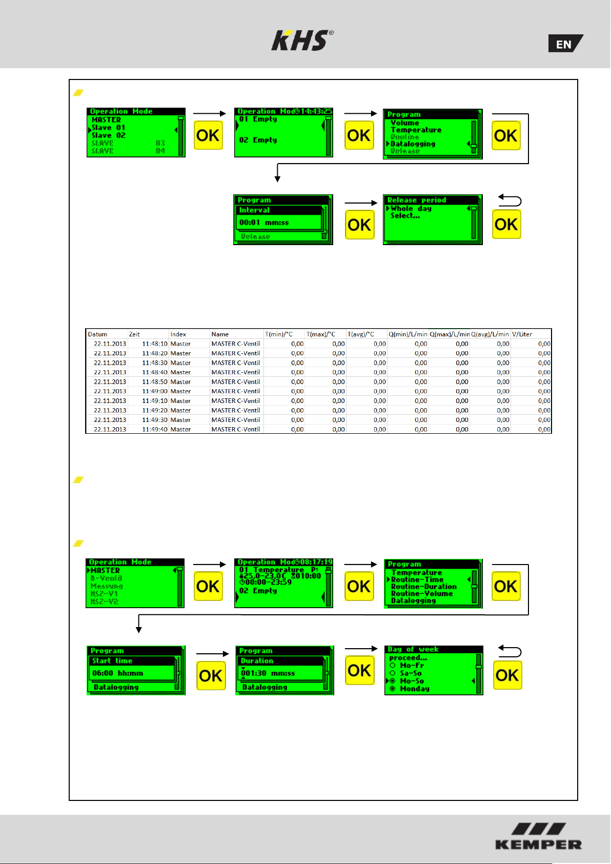
Configuration of datalogging
The following shows an exemplary
extract from a CSV log file. In the written
log file you can find a detailed listing of
the entire measured data. They are
sorted by date, time, index, name and
the measured data of the connected
measurement valve. Up to 12 million
lines can be saved.
Routines
If temperature flushing is configured, a
routine duration is automatically
activated. Generally speaking, it is
possible to choose between the following
routines:
Routine time
Page 26

K410068602008-00 / 09.2018 26
Routine Duration
Routine Volume
After your Control System have been successfully configured, you are
recommended to save the configuration as a backup file. If the KHS Mini Control
System -MASTER 2.0- is defective it can be quickly replaced and the
configuration can be read in. This saves having to configure everything again.
Page 27

K410068602008-00 / 09.2018 27
The two mentioned flushing programs can be switched using an external
manual switch. The electrical connection is shown in Chapter 2.2.
3.1.2.5 Logbook
The "Logbook" submenu provides a
facility for opening event logging. Press
the "↑" and "↓" keys to change between
the individual logbook entries. The
event log documents the water
exchange operations, error messages
and configuration changes made by the
Kemper KHS Mini Control System (see
the following illustration).
Up to 50,000 logbook entries can be
saved.
... ....
Ill: Illustration of a logbook entry index 9-10, configuration change
3.1.2.6 Change Program
With the KHS Mini Control System MASTER 2.0- it is possible to switch
between two flushing programs or to
block them using an external switch. The
programs can also be activated or
deactivated in the "Switch program"
submenu. The "External input" or
"External switch" can be assigned to a
program switch in this submenu.
Progr. Switchover Progr. Deactivate switchover
Block system/select program
Select external input action
The stored logbook entries can be saved through the USB interface on a USB
memory stick. This function is explained in detail in Chapter 5.
Page 28

K410068602008-00 / 09.2018 28
3.1.2.7 Valve manual mode
With the KHS Mini Control System MASTER 2.0-, it is possible to run a
function test of the valves using the
"Valve manual mode" submenu.
Furthermore, the valves can be
individually addressed during
maintenance. The functions are shown in
the following illustration.
Maintenance:
A function test is recommended after configuring the "Device settings"
submenu to rule out possible errors immediately.
Valve manual mode Select system crtl. Automatic mode
Open
Closed
3.1.2.8 Network setup
To establish a connection between the PC
and the KHS Mini Control System MASTER 2.0-, the required network
configurations can be set up in the
"Network setup" submenu.
Connection
Description
PC ↔ MASTER
The IP addresses of the two devices should not differ greatly
from each other.
PC ↔ LAN ↔ MASTER
You can obtain the appropriate parameters for integration
into your network from your system administrator
The following parameters are configured as factory defaults:
IP-Adresse: 10.1.23.150
Subnet: 255.255.255.0
Gateway: 10.1.23.1
Page 29

K410068602008-00 / 09.2018 29
Nework setup Setting the IP address
Setting the gateway
Setting the network mask
Prim. DNS Server einstellen
Setting the sec. DNS server
Setting the http user name
Tiggering a test email
Page 30

K410068602008-00 / 09.2018 30
Acknowledge error
All the errors that occur in the system are
sent to the KHS Mini Control System MASTER 2.0- and are signalled
acoustically by means of a buzzer. It is
possible to integrate an alarm relay (see
Chapter 2.2). In normal operation, the
alarm relay is energized ("pulled") with
voltage. If there is an error, the voltage
drops and an acoustic signal reports the
error. Here it does not matter what
different effect the error has on the
system. The control goes into alarm
latching and has to be acknowledged by
the user after the malfunction has been
repaired.
USB interface
Data can be transmitted comfortably with
the USB interface of the KHS Mini Control
System MASTER 2.0-. Data can be
imported by the device and also exported
from the device. It is also possible to use
the USB stick to install updates not only
for the Control System but also for the web
browser.
The USB menu is not visible in normal
mode. The menu is automatically
activated when a USB memory stick is
connected to the KHS Mini Control System
-MASTER 2.0-.
Max. storage capacity of the USB stick
16 GB
File system FAT32
1
2
3
A detailed list of
possible errors and
their corrections is
given in chapter 7.
Page 31

K410068602008-00 / 09.2018 31
USB menu
Meaning
Copy logbook to USB stick
All saved events are stored on the USB stick in
the form of a CSV file.
Copy flushing log to USB stick
All saved flushing processes are stored on the
USB stick in the form of a CSV file.
Copy configuration to USB stick
All settings are stored on the USB stick in the
form of a CFG file.
Read configuration from USB
stick
A saved configuration can be written from the
USB stick into the controls.
Copy data log to USB stick
When the "Datalogging" mode is activated, the
measured values recorded can be copied onto
the USB stick.
Software update from USB stick
Control System software update by means of a
UPE file, using the USB stick.
Copy web server from USB stick
Web browser update using the USB stick.
Web browser
The KHS Mini Control System -MASTER
2.0- is a web-based Control System. Using
a web browser, basic settings,
configurations and changes can be carried
out easily.
Chapter 6 concerns only the web browser interface. You can find the
complete operating instructions on the web browser with the button and
Downloads, or through the Service/ Download section of our website,
www.kemper-olpe.de.
To use the web browser, the following minimum system requirements must
be met:
Java script must be activated
Mozilla Firefox Version 22.0.1 or higher
Google Chrome Version 31.0 or higher
Windows Explorer Version 10.0 or higher
or an alternative browser Safari, etc.
Please note Chapter 3.1.2.8 and make sure you know which network
settings of the Control System are stored.
Page 32

K410068602008-00 / 09.2018 32
The WEB browser is subdivided into seven
menu interfaces. They can be selected
through the web browser tabs shown in
Fig. 6.1.1. In the individual menu
interfaces, you can make the basic
settings, the configurations and changes.
Use the WRITE TO CONTROL button to
save your parameters. If you do not want
to store the changes in the system, use
the
DISCARD CHANGES
button.
Ill. 6.1.1 Menu tab of the web browser
The web browser interface can also be used with a tablet PC or a
mobile phone. Here, the input interfaces are changed slightly. When
using with a mobile phone, the menu tabs can be seen over the
button (see below). The modes of functioning of the individual menu
interfaces remain unchanged; merely the graphics of the components
are not displayed.
The username “KHS”
and password "0000"
is the factory default.
Page 33

K410068602008-00 / 09.2018 33
In the "SYSTEM SETTINGS" menu
interface you can make settings for user
data, date / time, network, external switch
function and other settings.
User data
To
create a user for the web browser of your KHS Mini Control
System, choose a user name and a suitable password. To save the
settings, click the WRITE TO CONTROL button. After the settings
have been saved, you must identify yourself every time the web
browser is started. To do this, enter the user name you have just
chosen and the relevant password in the input dialogue that then
opens, as shown in Fig. 6.2.1. Use by several users is not possible.
Ill. 6.2.1 Input dialogue Identification
The username “KHS”
and password "0000"
is the factory default.
Page 34

K410068602008-00 / 09.2018 34
Date / Time
The
current time and current date of the KHS Mini Control System
-MASTER 2.0- are displayed in the grey boxes. To set the Control
System time, click the APPLY DATE/TIME button. This causes the
Control System to apply the date and time settings of your PC, for
example. The KHS Mini Control System -MASTER 2.0- can switch
automatically between daylight saving and standard time. If you do
not want this setting, click the button. If the button is showing
, the switchover between daylight savings and standard time is
not automatic
Netzwork
To
establish a connection between the PC and the KHS Mini Control
System -MASTER 2.0- using a web browser, the required network
configurations can be entered in the boxes IP address, Subnet,
Gateway, prim. DNS and sec. DNS.
You can obtain the appropriate parameters for
integration into your network from your system
administrator.
The following parameters are configured as factory
defaults:
IP address: 10.1.23.150
Subnet: 255.255.255.0
Gateway: 10.1.23.254
The network settings can only be loaded when the configuration
is loaded using a USB stick. They are not imported when the
configuration is loaded using the web server.
Program switch
With the KHS Mini Control System -MASTER 2.0- it is possible to
switch between two flushing programs. The programs can be
configured in the Operating modes menu interface and the individual
Control System can be added (see Chapter 6.2).
If the button for the program switchover is set to , the external
program switching is deactivated. If the button for the program
switchover is set to , the external program switching is active.
The names of the flushing programs can be changed with an entry
in the related box. Use the "Current operating mode" drop-down list
to manually switch the flushing programs in the web server and to
block them for maintenance purposes. Use the "External input"
drop-down list to set the operating mode of the external input.
Maintenance:
The two flushing programs mentioned above can
be switched using the web browser and can be
blocked for maintenance purposes.
Page 35

K410068602008-00 / 09.2018 35
Other settings
The
KHS Mini Control System -MASTER 2.0- can activate an internal
buzzer in case of faults. If the related button displays , the alarm
buzzer is activated.
If the related button displays , the alarm buzzer is not activated.
Using the drop-down menu you can also customise the language
setting of the control.
In the "DEVICE SETTINGS" menu
interface, the individual KHS Mini Control
System with integrated actuators and
sensors are logically linked to each other.
Selection interface
The "DEVICE SETTINGS" menu interface is a dynamic interface.
The selection interface of the installed KHS Mini Control System
are shown on the left-hand side. Click on the desired KHS Mini
Control System to open the relevant input box.
The changes must be written into the control after
every change in the input box. If another KHS Mini
Control System is selected immediately after a
change in the selection interface, the changes are
automatically discarded.
Page 36

K410068602008-00 / 09.2018 36
Input box
If a KHS Mini Control System is selected in the selection
interface, the input box appears on the right-hand side.
Use this box to allocate the related actuators and sensors
to the KHS Mini-Control System.
If an error occurs in the Control System, it can be
reported across the entire system. To do this, set the
button to . The remaining input options of the input
box are explained in the following.
Adding devices
Configuration (B valve)
Select control type
Choose the available control
types that can be used by the
selected KHS Mini Control
System from a drop-down list.
The KHS Mini Control System MASTER 2.0 - should control a B
valve in this sample project.
Select valve
The possible valves are selected from
a drop-down list. In this sample
project, the KHS Mini Control System
-MASTER 2.0- should actuate a KHS
VAV maximum flow isolating ball valve
with spring reset and servo drive.
Alarm relay reports system-wide error
Page 37

K410068602008-00 / 09.2018 37
Select sensor
The possible sensors are selected from
a drop-down list. In this sample
project, the KHS Mini Control System MASTER 2.0- should actuate a KHS
CONTROL PLUS
Save settings
To
allow the new parameters of the
input box to become effective, the
settings must by saved by clicking the
WRITE TO CONTROL button.
Page 38

K410068602008-00 / 09.2018 38
Configuration of the A valve
Select control type
Choose the available control types that
can be used by the selected KHS Mini
Control System from a drop-down list.
The KHS Mini Control System should
actuate an A valve in this sample
project.
Select the relevant B valve
Each A valve must be assigned to
a B valve. The available KHS Mini
Control System that are linked to
a B valve can be selected from a
drop-down list. The KHS Mini
Control System in this sample
project should be assigned to the
B valve of the KHS Mini Control
System -MASTER 2.0-.
Page 39

K410068602008-00 / 09.2018 39
Select valve
The possible valves are selected
from a drop-down list. In this
sample project, the KHS Mini
Control System should actuate a
KHS VAV maximum flow isolating
ball valve with servo drive.
Select sensor
The possible sensors are selected
from a drop-down list. The KHS
Mini Control System in this
sample project should actuate a
KHS temperature sensor Pt
1000.
Page 40

K410068602008-00 / 09.2018 40
Select the medium to be
monitores
Select the medium to be monitored
from a drop-down list. In this sample
project, it is cold water.
The temperature ranges are then
configured.
Save settings
For
the new parameters of the input
box to become effective, the settings
must be saved by clicking WRITE TO
CONTROL.
Page 41

K410068602008-00 / 09.2018 41
Configuration oft he C valve
Select control type
Choose the available control
types that can be used by the
selected KHS Mini Control
System from a drop-down list.
The KHS Mini Control System
should actuate a C valve in this
sample project.
Select valve
Die möglichen Ventile werden
mittels einer Dropdownliste
gewählt. Die KHS Mini Systemsteuerung soll im gegebenen
Musterprojekt ein KHS VAVVollstromabsperrventil mit Federrückzug und Stellantrieb ansteuern.
Page 42

K410068602008-00 / 09.2018 42
Select sensor
The possible sensors are selected from
a drop-down list. The KHS Mini Control
System in this sample project should
actuate a KHS temperature sensor Pt
1000.
Page 43

K410068602008-00 / 09.2018 43
Select the medium to be
monitored
Select the medium to be monitored
from a drop-down list. In this sample
project, it is cold water.
The temperature ranges must then be
configured.
Select sensor
The possible sensors are selected from
a drop-down list. In this sample
project, the KHS Mini Control System
should actuate a KHS CONTROL PLUS
Page 44

K410068602008-00 / 09.2018 44
Save settings
For
the new parameters of the input
box to become effective, the settings
must be saved by clicking WRITE TO
CONTROL
Configuration of the safety device
Select control type
Choose the available control types
that can be used by the selected KHS
Mini Control System from a drop-down
list. In this sample project, the KHS
Mini Control System should function
as a safety valve
Page 45

K410068602008-00 / 09.2018 45
Select valve
The possible valves are selected from a
drop-down list. In this sample project,
the KHS Mini Control System should
actuate a KHS VAV maximum flow
isolating ball valve with servo drive.
Save settings
For
the new parameters of the input
box to become effective, the settings
must be saved by clicking WRITE TO
CONTROL.
Page 46

K410068602008-00 / 09.2018 46
Configuration of measurement
Select control type
Choose
the available control types that
can be used by the selected KHS Mini
Control System from a drop-down list.
The KHS Mini Control System -SLAVEin this example should act as a
measurement SLAVE.
Select sensor
The
possible sensors are selected
from a drop-down list. The KHS Mini
Control System - SLAVE - should be
assigned to a KHS CONTROL PLUS.
Page 47

K410068602008-00 / 09.2018 47
Save settings
For
the new parameters of the input
box to become effective, the settings
must by saved by clicking the WRITE
TO CONTROL button.
Configuration of the KHS HS2 Hygiene flushing box V1
Change Name
…V1 Connection right
…V2 Connection left
Use the APPLY NAME button to transmit
the selected system name
.
The KHS HS2 hygiene flushing box is displayed visually
.
Page 48

K410068602008-00 / 09.2018 48
Select control type
A control type (C valve) is assigned to
the KHS HS2 hygiene flushing box by
means of a drop-down list.
Select sensor
The
possible sensors are selected from
a drop-down list. A KHS temperature
sensor Pt 1000 can be assigned to the
KHS HS2 hygiene flushing box.
Select the medium to be
monitores
Select
the medium to be monitored
from a drop-down list. In this sample
project, it is cold water. The
temperature ranges are then
configured.
Page 49

K410068602008-00 / 09.2018 49
Select valve
An internal volume flow sensor can be
added to the KHS HS2 hygiene flushing
box by means of a drop-down list.
Save settings
For
the new parameters of the input
box to become effective, the settings
must by saved by clicking the WRITE
TO CONTROL button.
Page 50

K410068602008-00 / 09.2018 50
In the "OPERATING MODES" menu
interface, the control-specific TIMERS are
configured for the KHS Mini Control System.
Depending on the control type, a TIMER
defines flushing times, measurement
intervals, backup times, routine intervals,
temperature flushing etc.
Selection interface
In the "OPERATING MODES" menu interface, you will
find the selection interface of the added KHS Mini
Control System on the left-hand side. Click the desired
KHS Mini Control System to open the input box.
1
2
The changes must be written into the
control after every change in the
input box. If another KHS Mini
Control System is selected
immediately after a change in the
selection interface, the changes are
discarded.
1
Page 51

K410068602008-00 / 09.2018 51
Input box
If a KHS Mini Control System is selected in
the selection interface, the relevant input
box appears on the right-hand side.
Click the ADD LINE button to add up to 16
lines to the TIMER. Press the button to
delete the line in question from the TIMER.
Click the RESORT TIMER button to delete
all deactivated lines and to push empty
lines to the back. The remaining input
options in the lines are explained below.
Ill. 6.3.1 Overview of system commissioning for the sample project
The
selected times and temperatures serve as examples. The values must
always be set for each building and for each type of use and medium so that
representative measurement values are generated and intended use is
maintained for the system.
2
2
Page 52

K410068602008-00 / 09.2018 52
Configuration of time control (A valve)
Select type
After
a line has been added using ADD
LINE, the line type is selected. The KHS
Mini Control System in this sample
project is connected to an A valve. To
time control the water exchange, the
"Time flushing" line type must be
selected from a drop-down list.
Define times
Af
ter a line type has been selected,
define the times. In the "Time control"
line type, a starting time and the
duration of the water exchange must be
stated. Furthermore, the desired
weekday can be selected from a dropdown list. Click the box of the weekday
in question to activate it with a check
mark.
Page 53

K410068602008-00 / 09.2018 53
Save settings
the new parameters of the input box to
become effective, the settings must by
saved by clicking the WRITE TO
CONTROL button.
Configuration of volume flushing (A valve)
Select type
After
a line has been added using ADD
LINE, the line type is selected. To volume
control the water exchange, the "Volume
flushing" line type has to be selected
from a drop-down list.
Page 54

K410068602008-00 / 09.2018 54
Define times
Ist
er a line type has been selected,
define the times. In the "Volume control"
line type, a starting time, the duration
and the volume of the water exchange
must be specified. Furthermore, the
desired weekday can be selected from a
drop-down list. Click in the box of the
weekday in question to activate it with a
check mark.
Save setting
For
the new parameters of the input
box to become effective, the settings
must by saved by clicking the WRITE TO
CONTROL button.
Page 55

K410068602008-00 / 09.2018 55
Configuration of temperature flushing (A valve)
Select type
(Temperature flushing)
After
a line has been added using ADD
LINE, the line type is selected. The KHS
Mini Control System in the sample
project is linked to a temperature
measurement valve. To temperature
control the water exchange, the
"Temperature control" line type has to be
selected from a drop-down list.
Define times
I
a line type has been selected, define
the times. A starting and stopping time
has to be specified for the "Temperature
flushing" line type. Furthermore, the
desired weekday can be selected from a
drop-down list. Click in the box of the
weekday in question to activate it with a
check mark.
Page 56

K410068602008-00 / 09.2018 56
Routine time
In
this sample project, it is cold water.
The cold water temperature in winter
could always be below the starting
temperature. Nevertheless, to prevent
stagnation, routine water exchanges can
simulate operation for the intended
purpose. The "Routine" line type can be
selected from the drop-down list.
The desired weekday can also be
selected from a drop-down list. Click in
the box of the weekday in question to
activate it with a check mark.
Routine time
If there is no temperature flushing within 7
days, water exchange is guaranteed
through the "Routine time" operating mode.
In the "Routine time" operating mode, the
starting time, the duration and the
weekdays of the water exchange can be
defined.
Routine duration
If there is no temperature flushing within
the configured interval, the water exchange
is guaranteed through the "Routine
duration" operating mode. To accomplish
that, the decisive interval (max. 168 h) and
the duration of the water exchange can be
stored in the "Routine duration" operating
mode.
Routine volume
If there is no temperature flushing within
the configured interval, the water exchange
is guaranteed through the "Routine volume"
operating mode. To accomplish this, the
decisive interval (max. 168 h), the volume
and the maximum flushing time of the water
exchange can be assigned to the "Routine
volume" operating mode.
Save settings
For the new parameters of the input
box to become effective, the settings
must by saved by clicking the WRITE
TO CONTROL button.
Page 57

K410068602008-00 / 09.2018 57
Configuration of a KHS HS2 Hygiene flushing box V1 (interval flushing)
Select interval
After
a line has been added using ADD
LINE, the line type is selected. The
"Routine duration" line type is selected
from the drop-down list.
Here, the "Routine duration" line type
corresponds to one interval flushing
operation.
Define times
After
a line type has been selected,
define the times. In the "Routine
duration" line type, the duration and
the interval of the water exchange must
be specified.
Save settings
Fo
r the new parameters of the input
box to become effective, the settings
must by saved by clicking the WRITE
TO CONTROL button.
Page 58

K410068602008-00 / 09.2018 58
Configuration of the safety device
Select type
After a line has been added using ADD
LINE, the line type is selected. The
"Release" line type is selected from the
drop-down list.
Define time
Af
ter a line type has been selected,
define the times. A starting and stopping
time has to be specified for the "Release"
line type. Furthermore, the desired
weekdays can be selected from a dropdown list. Click in the box of the weekday
in question to activate it with a check
mark.
Configuration of measurement (datalogging)
Select type
Na
er a line has been added using ADD
LINE, the line type is selected. The KHS
Mini Control System in this sample
project is connected to a KHS Control
Plus flow measurement valve. To record
the flow measurement valve
measurement data at the same time, the
"Datalogging" line type must be selected
from a drop-down list.
Page 59

K410068602008-00 / 09.2018 59
Define times
After a line type has been selected,
define the times. A starting and stopping
time has to be stated for the
"Datalogging" line type. Furthermore,
the desired weekdays can be selected
from a drop-down list. Click in the box of
the respective weekday to activate it with
a check mark. The interval time states
the storage rate of the measurement
values
.
Save settings
For the new parameters of the input
box to become effective, the settings
must by saved by clicking the WRITE
TO CONTROL button.
Page 60

K410068602008-00 / 09.2018 60
In the „OVERVIEW“ menu interface, the
configured valves and the linked sensors
are shown in an overview. Pure
measurement valves are not listed in the
“OVERVIEW”.
Overview
The overview merely shows the
current states. No configurations can
be carried out on this interface.
Click a valve to open the input box of
the "SYSTEM SETTINGS" menu
interface of the selected component.
If a valve is highlighted in black, this
means it is closed. If the valve is
highlighted in grey, it is open. If the
valve is highlighted in red, there is a
fault.
Manual mode / Automatic
The actuators can be triggered
manually. Click the button to open a
selection window. Use the selection
window to choose between three
settings (C valve) or five settings (A/B
valve) from a drop-down list. The
button indicates a fault in the system.
Automatic = Standard setting
Manual OPEN = Opens valve
Manual CLOSE = Closes valve
Group OPEN = With the A valve, the B
valve also opens
Group CLOSE = both close again
After
a setting has been selected, the
duration of the setting can be defined.
Use the APPLY button to apply the
setting. Press the CANCEL button to
cancel the action.
60
Page 61

K410068602008-00 / 09.2018 61
The „CURRENT VALUES“ menu interface
shows the current values oft he connected
KHS Mini Control System and their sensors.
Click
the button to open the
input box of the "DEVICE SETTINGS"
menu interface of the selected KHS
Mini Control System.
Page 62

K410068602008-00 / 09.2018 62
You can use the "DATA TRANSFER"
menu interface to load
configurations, software updates,
logbook entries and the created
datalogging files.
Page 63

K410068602008-00 / 09.2018 63
Software update
The "Software update" function can be
used to install a software update on the
connected KHS Mini Control System. To
do this, click the Search button. The
UPE files open in the window that then
opens, see Fig. 6.7.1. After the LOAD
UPDATE button has been pressed, a
confirmation appears as shown in Fig.
6.6.2. Click the OK button to load the
selected setup into the Control System.
Ill. 6.7.1 Selection dialogue „Upload setup file“
Ill. 6.7.2 „Delete software update“ confirmation
As a precautionary measure, please backup your configuration before
making an update.
Page 64

K410068602008-00 / 09.2018 64
Configuration
Loading a configuration from a file
The "Configuration" function can be
used to install an existing configuration
in the connected KHS Mini Control
System. To do this, click the Search
button. The CFG file opens in the
window that then opens, see Fig. 6.7.3.
After the LOAD CONFIGURATION FROM
FILE button has been clicked, the
selected configuration is then loaded
into the Control System.
The network and e-mail settings can
only be loaded when the configuration
is loaded using a USB stick. They are
not imported when the configuration
is loaded using the web server.
Backing up the configuration
You can use the "Configuration"
function to backup parameterised
configurations of the connected KHS
Mini Control System to your PC. To do
this, click the WRITE CONFIGURATION
TO FILE button. In this window, see Fig.
6.7.4, you can back up the CFG file to
the desired folder on your PC.
Ill. 6.7.4 Selection dialogue „Back up configuration file“
After successfully configuring your Control System, you are
recommended to save the configuration as a backup file. If the
KHS Mini Control System -MASTER 2.0- is defective, it can be
quickly replaced and the configuration can be read in. This
saves having to configure everything again.
Ill. 6.7.3 Selection dialogue „Upload configuration file“
Page 65

K410068602008-00 / 09.2018 65
Logbook
You can use the "Logbook" function to
open and save the event log as a CSV
file. The event log documents the water
exchange operations, error messages
and configuration changes made by the
Kemper KHS Mini Control System.
Based on the documentation about the
location, duration of the water
exchange and the temperatures,
recordings can be made across a
defined time period to verify the state
of hygiene of the drinking water
system. To open the CSV file, click
OPEN LOGBOOK AS CSV. A dialogue
window then opens, where you can
select whether the flushing log should
be saved or if it should be immediately
opened (see Fig. 6.7.5).
The KHS Mini Control System have a facility
to be used as measuring instruments. To do
this, the Control System that are connected
to a sensor, as described in Chapter 6.3, are
configured. Use the "Datalogging" function
to generate, delete and save the recorded
measurement data records in the form of a
CSV file on the PC. Up to 12 million lines can
be backed up. Click the
CREATE LOGFILE button to generate the
current CSV file, which is not yet completely
full. Click the CSV file to open a dialogue as
shown in Fig. 6.7.6. Here you can select
whether the flushing log should be saved or
immediately opened. Use the button to
open a query as shown in Fig. 6.7.7. Click
OK to delete the selected file.
Ill. 6.7.5 Opening the CSV log file dialogue
Page 66

K410068602008-00 / 09.2018 66
Ill. 6.7.6 Openeing the CSV data log file dialogue
Ill. 6.7.7 „Delete file“ confirmation
Ill. 6.7.8 shows an extract of a CSV log file.
In the log file you will find a detailed list of
the entire measured data; sorted by date,
time, index, name and the measured data of
the connected measuring valve.
Ill. 6.7.8 Illustration of an extract of a CSV log file
As described in Chapter 6.3, the sampling interval of the measured
values can be set using the "OPERATING MODES" menu interface.
Page 67

K410068602008-00 / 09.2018 67
If errors or warning messages occur, the
KHS Mini Control System -MASTER 2.0- can
send them directly to the plant operating
organisation by e-mail.
In the "EMAIL ADMINISTRATION" menu
interface, a selection of error and warning
messages can be individually configured.
Furthermore, the e-mail configuration is set
with the user, server and login information
functions.
Page 68
K410068602008-00 / 09.2018 68
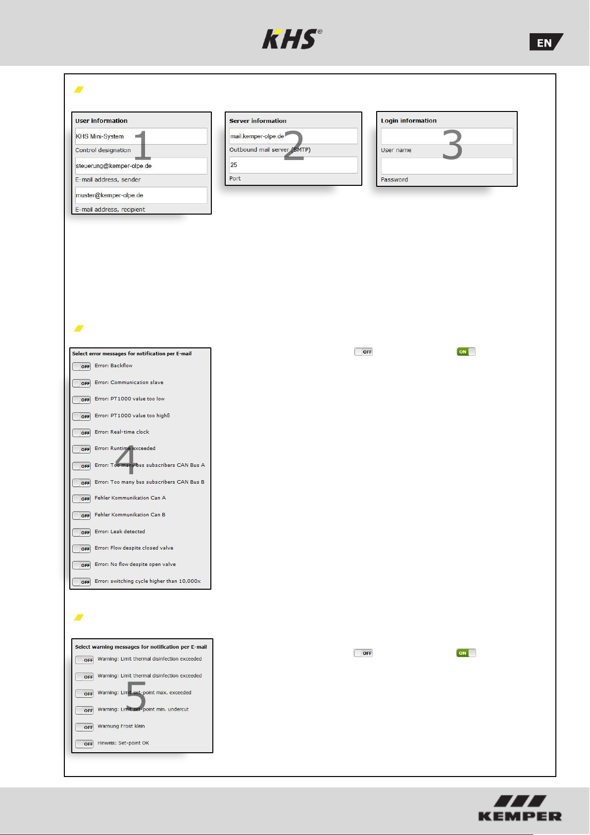
User information | Server information | Login information
To enable the KHS Mini Control System MASTER 2.0- to send error and warning
messages to the plant operating
organisation, the e-mail settings have to be
configured. Here, an internal company e-
mail account can be created, or an
independent provider can be used if he
works without encryption. The control name
can be used to allocate a location, e.g.
Cologne Gymnastics Hall.
Select error messages for notification per email
If the button is set to , the relevant
notification about a possible error is
activated. If an error occurs, an error
message is sent to the plant operator by email.
Select warning messages for notification per email
If the button is set to , the relevant
notification about a possible warning is
activated. If a warning occurs, an error
message is sent to the plant operating
organisation by e-mail.
Page 69

K410068602008-00 / 09.2018 69
Error description and error handling
Error description / Error handling
Status
LED
Status LED
Status LED
Status LED
Status LED
General error
Flashes red
Backwater in drain
Drain is clogged or cannot accept
the flushing volume.
Check the drain
channel, channel
acceptance capacity.
Error message!
Defective control will be
completely blocked
Backwater in drain
Float switch on the drain has a
cable break
Replace cable / switch
Error message!
Defective control will be
completely blocked
Temperature flushing
switched off during
runtime
Medium did not reach the switch-
off temperature in the set time
Check the installation
setup and the
maximum flushing
time.
Error message!
Temperature operating
mode is blocked in the
defective control.
Volume flushing
switched off during
runtime
Set volume not reached
Check the installation
setup and the
maximum flushing
time.
Error message!
Volume operating mode is
blocked in the defective
control.
PT1000 value too
high
Sensor defective / No sensor
available
Replace sensor / Check
inputs on the MASTER
Error message!
Temperature flushing
operating mode is blocked
in the defective control.
PT1000 value too low
Sensor defective / No sensor
available
Replace sensor / Check
inputs on the MASTER
Error message!
Temperature flushing
operating mode is blocked
in the defective control.
Leak on sensor
Pipe failure, moisture on the
sensor
Check the local area
and remove the
moisture
The safety valve is
blocking the system.
Real-time clock data
inconsistent
Data in the clock are not
consistent
Check the time & date
and adjust if necessary.
Check battery/replace
if applicable
All time-based services
are running on incorrect
time/date.
Flow detected with
valve closed"
Flow is detected by the flow
measurement valve when the
valve is closed
Check the function of
the flushing valve
Error message! The
involved valve will be
blocked.
"No flow detected
despite open valve"
No flow is detected during a
flushing process.
Check the flushing line
and the flushing valve
Error message! The
involved valve will be
blocked.
Page 70

K410068602008-00 / 09.2018 70
Error description / Error handling
Status
LED
Status LED
Status LED
Status LED
Auswirkung
Bus error
Flashes orange
No response from the
SLAVE
Cable break, incorrect installation,
interference fields
Check CAN bus cables
and installation
Faulty SLAVE does not
function
No response from the
SLAVE
SLAVE does not have voltage
Restore SLAVE power
supply
Faulty SLAVE does not
function
No response from the
SLAVE
SLAVE with its corresponding
serial number no longer part of
the plant (e.g., after a
replacement)
Assign the correct
serial number to the
SLAVE or delete the
device from the system
Faulty SLAVE does not
function
CAN bus line fault
Cable break, incorrect installation,
interference fields
Check CAN bus cables
and installation
CAN bus and all SLAVEs
do not function.
Too many bus
subscribers
CAN bus A
More than 31 SLAVEs are
connected to
CAN bus A
Rewire the BUS
subscribers or change
the position of the
MASTER in the bus
system.
CAN bus A faulty.
Communication and
functions can be impaired.
Too many bus
subscribers
CAN bus B
More than 31 SLAVEs are
connected to
CAN bus B
Rewire the BUS
subscribers or change
the position of the
MASTER in the bus
system.
CAN bus B faulty.
Communication and
functions can be impaired.
Communication error
CAN bus A
Cable break, incorrect installation,
interference fields
Check CAN Bus A
cables and installation
Affected SLAVEs do not
function
Communication error
CAN bus B
Cable break, incorrect installation,
interference fields
Check CAN Bus B
cables and installation
Affected SLAVEs do not
function
Page 71

K410068602008-00 / 09.2018 71
Description of warnings / notices
Status
LED
Status LED
Status LED
Status LED
Status LED
Warnings
flashes
red
Operating cycles
exceed 20,000
The VAV on the defective SLAVE
has performed more than 20,000
operating cycles
Replace VAV bonnet in
accordance with the
maintenance manual
and reset the operating
cycles.
The warning message
cannot be confirmed.
SLAVE continues to
operate normally.
No influence
Thermal disinfection
limit exceeded
The monitored temperature has
exceeded the set limit value.
Check to see if it needs
to be set otherwise.
Entry in logbook and
optional message via
email.
Set-point max. limit
exceeded
The monitored temperature has
exceeded the set limit value.
Check to see if it needs
to be set otherwise.
Entry in logbook and
optional message via
email.
Set-point min. limit
undercut
The monitored temperature has
undercut the set limit value.
Check to see if it needs
to be set otherwise.
Entry in logbook and
optional message via
email.
Frost protection limit
undercut
The monitored temperature has
undercut the set limit value.
Prevent danger of
valves freezing up.
Entry in logbook and
optional message via
email.
Notes
No
influen
ce
Set-point OK
Notice that the monitored
temperature is in the target
range.
No action needed!
Entry in logbook and
optional message via
email.
Lights
up
green
Control in standby
No flushing pending. Control in
standby
No action needed!
No influence
Flash
es
gree
n
Flushing is running
The valve on the involved control
is flushing / is open.
No action needed!
Entry in logbook.
Accessories | Spare parts
Optionally available accessories
FIGURE
KHS VAV with servo drive 230 V
686 04
KHS VAV plus with spring-reset servo drive (230 V)
686 05
KHS drain with overflow monitor
688 00
KHS temperature sensor fitting Pt 1000
628 0G / 629 0G
KHS flow measurement valve
638 4G / 138 4G
Leakage water sensor
620 00 001
Page 72

K410068602008-00 / 09.2018 72
Spare parts
Pos.
Art.-No.
Designation
Note
Installation advice
(1)
6260201900
Network cable for KHS
Mini Control System
MASTER 2.0;
hardware stand 2.0
For Master
hardware stand
2.0
(2)
6860202000
Network cable for KHS
Mini Control System
MASTER 2.0;
hardware stand 2.01
For Master
hardware stand
2.01
(3)
6860202100
Network cable for KHS
Mini Control System
MASTER 2.0;
For hardware
stand 2.0
additionally cable
6860202000 is
required.
Service department application technology
Tel. +49 2761 891-0
(4)
6860202200
Micro SD card for
network module in KHS
Mini Control System
MASTER 2.0
---
Service department application technology
Tel. +49 2761 891-0
1 2 3
4
Page 73

K410068602008-00 / 09.2018 73
KHS cable list
This list of cables only shows examples
of applications. The exact design of the
cables in questions must be carried out
on site by the planner on the basis of
Designation Art.-No.
[-] [-] [mm²] [mm] [m] [-]
KHS quarter turn stop
valve PLUS with spring
reset servo drive (24 V)
KHS quarter turn stop
valve with servo drive
(24 V)
KHS quarter turn stop
valve PLUS with spring
reset servo drive (230V)
KHS quarter turn stop
valve with servo drive
(230 V)
KHS free drain with
overflow sensor
686 01 015…032
686 00 015…032
686 05 015…032
685 15 032…050
686 04 015…032 5 x 1.50 mm² 1000 NYM-J
688 00 020...032 2 x 2 x 0.80 mm **
the ambient conditions (temperature,
frequency, routing type, mechanical
load).
Cable cross-section /
diameter
3 x X mm²
(power supply)
+
2 x 2 x 0.80 mm **
(position feedback)
5 x X mm²
(power supply)
+
2 x 2 x 0.80 mm **
(position feedback)
3 x 1.50 mm² 1000 NYM-J
Max. cable
length
700 (X=1,50)
10
00 (X=2,50)
250 (X=1,50)
450 (X=2,50)
1000
Cable type*
NYM-J
+
J-Y(ST)Y
NYM-J
+
J-Y(ST)Y
J-Y(ST)Y
Kemper CONTROL PLUS
flow measurement valve
Vortex principle
Kemper CONTROL PLUS
flow measurement valve
Vortex principle
KHS flow and
temperature sensor
Pt 1000
Leakage water sensor 620 00 00100 2 x 2 x 0.80 mm ** 500 J-Y(ST)Y
CAN bus cable
The application is based on
the ISO 11898 international
standard.
138 4G 015…050
138 6G 015…050 4 x 2 x 0.80 mm ** 300 J-Y(ST)Y
628 0G 015...050
629 0G 015...050
4 x 2 x 0.80 mm **
2 x 2 x 0.80 mm ** 1000 J-Y(ST)Y
1 x 2 x 0.34 mm² **
1 x 2 x 0.50 mm² **
1 x 2 x 0.75 mm² **
300 J-Y(ST)Y
300
500
1000
CAN bus cable
* Possible cable type for fixed routing, without mechanical load
** Shielded cable lead
According to VDE 0815: The specification of signal transmission cables with
respect to the diameter is specified in mm.
Page 74

K410068602008-00 / 09.2018 74
Appendix
The following chapter shows the various
valve technologies based on exemplary
illustrations.
10.1.1 A-/B Valve technology
In A/B valve technology,
several riser branches or
distribution lines are connected
to a common flushing line.
Here, one A valve and the B
valve are successively opened
and closed together. This
guarantees that there is no
idling in the flushing lines and
there is no water exchange
between the pipelines to be
flushed.
Example of a flushing process:
A1 and B1 open in accordance
with the specifications, A1 and
B1 close
A2 and B1 open in accordance
with the specifications, A2 and
B1 close
A3 and B1 open in accordance
with the specifications, A3 and
B1 close
A4 and B1 open in accordance
with the specifications, A4 and
B1 close
Please note:
If valve A1 is flushing, the
pending flushing processes of
other valves are blocked. With
temperature flushing, these
are then carried out
successively by the system.
A Valve
B Valve
KHS maximum flow isolation
ball valve with servo drive
Figure 686 04 230 V AC
KHS PLUS maximum flow isolation ball
valve with servo drive and spring reset
Figure 686 05 230 V AC
Page 75

K410068602008-00 / 09.2018 75
10.1.2 C valve technology
KHS PLUS maximum flow isolation ball
valve with servo drive and spring reset
Figure 686 05 230 V AC
C valve technology makes it
possible to exchange the water of
an individual riser branch or of
one individual distribution line
independent of the other water
exchanging valves.
Page 76

K410068602008-00 / 09.2018 76
You can find the write-in form at: www.kemper-olpe.de at "Building Technology" in the
service download area.
Page 77

K410068602008-00 / 09.2018 77
Page 78

K410068602008-00 / 09.2018 78
K410068602008-00 / 09.2018
Gebr. Kemper GmbH & Co. KG
Harkortstraße 5
D-57462 Olpe
Service-Hotline +49 2761 891-800
info@kemper-olpe.de
www.kemper-olpe.de
 Loading...