

Page 1

Technology you can count on
Operator’s manual
Version B 0702
English
No. : 97441
ROTARY HARVESTING
UNITS
330
Maschinenfabrik KEMPER GmbH & Co. KG • D- 48694 Stadtlohn
P.O. Box 1352 • Tel.: +49 (0) 25 63 / 88-0
E-mail: Info@Kemper-Stadtlohn.de
Internet: www.kemper-stadtlohn.de
Page 2

Design and model
claims
The construction and function of our products are subject to technical continuous and
further development, which means information and data pertaining to a delivery are
not binding.
Maschinenfabrik KEMPER GmbH & Co. KG
Postfach 1352 – D-48694 Stadtlohn
Tel. +49(0) 2563 / 88-0
E-mail: Info@Kemper-Stadtlohn.de
web: www. Kemper-Stadtlohn.de
Page 3

0611
Introduction
Foreword
Carefully read this operating manual to
familiarise yourself with the correct operation
and maintenance of the machine and to
prevent injury and damage to the equipment.
This operating manual and the safety labels
attached to the machine are available in
various languages (contact your KEMPER
dealer for details).
This operating manual is an integral part of
the delivery. When the machine is sold, the
manual must be handed over with the
equipment to the new owner.
All dimensions in this operating manual are in
metric units. Use only fitting parts and screws.
The directions of "RIGHT" and "LEFT" are
indicated relative to the direction of forward
travel of the machine.
Enter the product identification codes in the
respective section. Please copy all digits and
check them to be sure that they are correct. In
the event of theft of the machine, these codes
might assist the police in their enquiries.
These codes are also required by the KEMPER
dealer for spare part orders. We recommend
noting the codes also in another document.
The machine has been thoroughly tested and
inspected by your dealer prior to delivery.
The attachment may only be used for its intended
purpose and in line with standard agricultural
work practices (see section "Proper use"). Any
other use is deemed improper. The manufacturer
shall not be liable for damage caused by improper
use. Proper use includes compliance with the
operating, maintenance and repair instructions
and schedules laid down by the manufacturer.
The attachment may only be operated, serviced
and repaired by persons who are fully familiar
with the device and have been instructed
regarding possible risks. Always adhere to all
relevant accident prevention regulations and other
safety practices. Also observe the relevant
occupational health and road traffic regulations.
Modifications to the attachment are forbidden.
The manufacturer shall not be liable for any
damage resulting directly or indirectly from
modifications made to the equipment.
0611
Page 4

0611
Introduction
Inspection completed prior to delivery
The following tests, inspections, settings and maintenance tasks have been
completed prior to the delivery of the machine:
0611
1. Attachment properly mounted
Visual inspection for damage
2.
caused during transportation.
3. Lubricant applied to all lubrication
.
points
4. Friction clutches released.
5. Transmission checked for leakage.
6. All moving parts tested for smooth
movement
7. All hydraulic lines and connections
tested for leakage - all lines and
connections are tight.
.
8. All adhesive labels are OK.
9. Customer instructed in the operation of
the device, with special reference to risks
and safety measures.
Operating manual handed over to
10.
customer
.
Date:
Signature of dealer/Kemper
specialist:
Page 5

0611
Introduction
0611
Page 6

0611
Table of contents
Page
Safety instructions............................................ 1
Permitted use................................................... 1.1
Identification of safety instructions.................... 1.2
Hazard symbols................................................ 1.3
Accident prevention regulations ....................... 1.4
Mechanical safety............................................. 1.5
Safety instructions for assembling and
removing the harvesting implement.................. 1.6
Safety instructions for working on equipment
containing fluids under high pressure...............1.8
Safety instructions for welding and for the
heating of components..................................... 1.9
EC declaration of conformity ........................ 2.0
Transfer of ownership of the equipment........... 2.1
Product liability – Obligation to provide
information........................................................ 2.2
General............................................................... 4
Description of the equipment............................ 4.1
Design of the harvesting implements with
description of the most important components. 4.2
Dimensions and weights of the implements ..... 4.3
Maintenance and testing .................................. 4.4
Tightening torques for metric bolts and screws 4.5
Transporting the equipment.............................. 4.6
Travelling on public highways........................... 4.7
Requirements made of forage harvesters ........ 4.8
Assisted steering.............................................. 4.9
Individual type approval.................................. 4.10
Hydraulic system............................................... 7
Valves............................................................... 7.1
Throttles ........................................................... 7.2
PTO..................................................................... 9
Description of interaction of the various
elements........................................................... 9.1
Description of the drives/transmissions with
inlet, drain and breather bores.......................... 9.2
Oil grades and capacities of the various
drives/transmissions......................................... 9.3
Lubricating schedule for the basic machine...... 9.4
Page
Clutches...........................................................10
Starting-off clutch (700 Nm) ...........................10.1
Starting-off clutch (800 Nm) ...........................10.2
Starting-off clutch (900 Nm), liquid-cooled .....10.3
Dismantling the clutches ................................10.4
Maintenance and service work ...................... 11
Star ratchet.....................................................11.1
Blades............................................................11.2
Maintenance of the crop intake and cutting
area................................................................11.3
Inspecting the crop guide track ......................11.4
Scrapers.........................................................11.5
Attachment frame........................................... 11.6
Faults and their causes..................................11.7
Operations Instructions..................................12
Starting, Turning, Reversing...........................12.1
Downed Maize, WPS .....................................12.2
Attaching and Detaching................................15
Attachment to John Deere forage
harvesters........................................................16
Make a note of serial number.........................30
All information, illustrations and specifications in this manual are based on the
latest information available at the time of publication. The right is reserved to
make changes at any time without notice.
0611
Page 7

Chapter 1 Chapter 1
Point 1.1/1.2 Point 1.1/1.2
0401
1
Safety instructions
Safety instructions
0401
1.1 Working with the
implement:
The Kemper harvesting implement with interface for selfpropelled forage harvesters is suitable for row-independent
harvesting of silage maize, whole crop silage, lucerne, oil seed
rape, field beans, sorghum, sunflowers and other stalk-type
crops.
This machine may only be used for the purpose for which it is
intended, in keeping with equipment safety regulations. Failure to
do so will nullify all liability in the event of any resulting injury or
damage. Use for the purpose for which it is intended also
includes the observation of our operating and maintenance
instructions and sole use of genuine Kemper replacement parts.
The harvesting unit may only be used, serviced and repaired by
persons who are familiar with the operation of this equipment or
who have been instructed regarding the hazards involved. (see
UVV 1.1 §1)
Important:
It is forbidden to work on the header (removal of blockages,
service and repair work) while the harvester engine is still
running.
The header has undergone CE testing and is marked
accordingly.
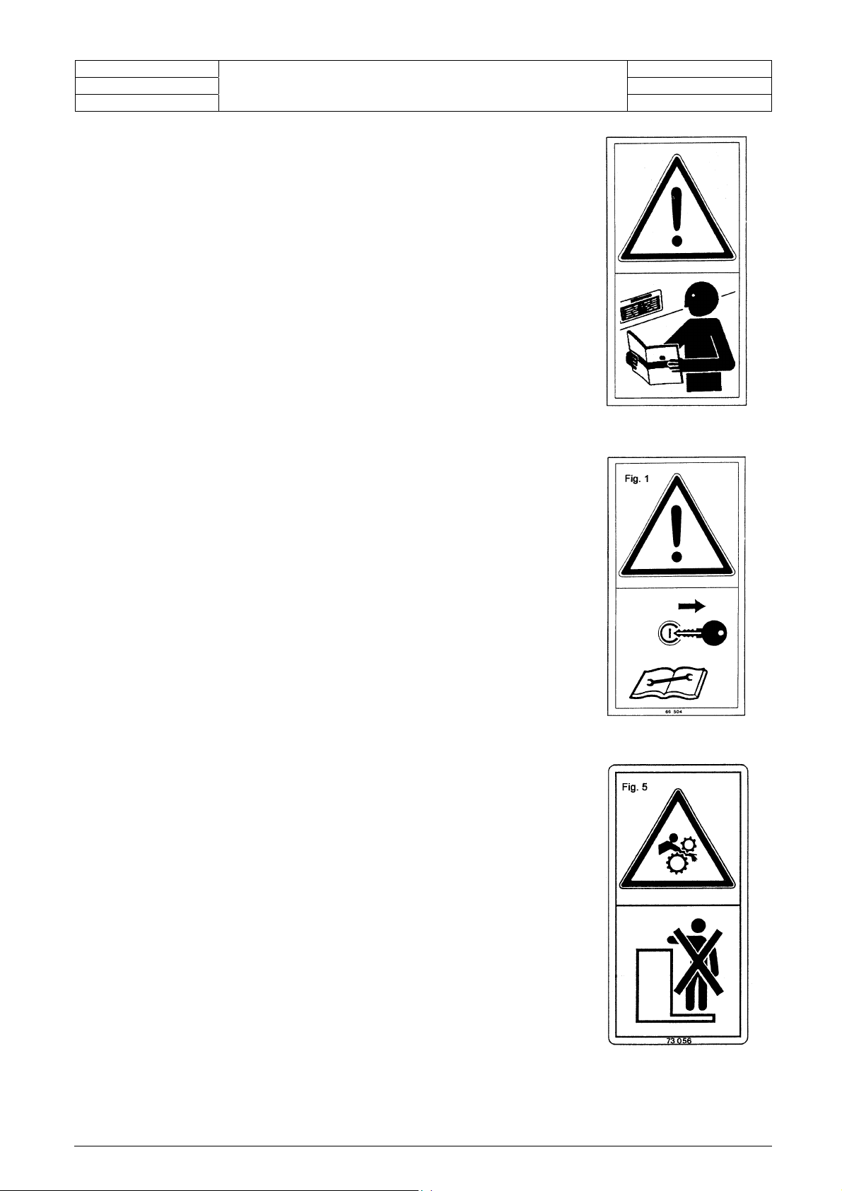
1.2 Recognising
warnings
This sign draws your attention to the safety
instructions mounted on the machine and
contained in the safety instructions.
You must observe all safety and general
accident prevention instructions.
Page 8
Chapter 1 Chapter 1
Point 1.3 Point 1.3
0401
Safety instructions
0401
1.3 Safety
instructions:
Read the safety instructions and warning
signs mounted on the machine and contained
in the operating instructions carefully.
Make sure that all signs can be easily read.
Replace any signs which cannot be clearly
read.
Before you start working with the machine,
make sure you are familiar with the overall
machine operation.
Always ensure the machine is in good
condition.
Unauthorised modifications will impair the
proper functioning of the machine.
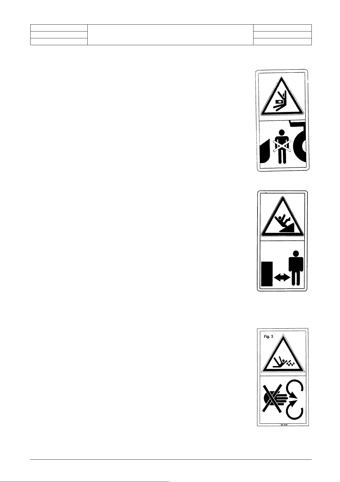
Switch off the engine and remove the
ignition key before commencing all
service and repair work.
Do not climb on to the machine before
the power system has cut out,
the engine has stopped and the
ignition key has been removed.
Page 9
Chapter 1 Chapter 1
Point 1.3 Point 1.3
0401
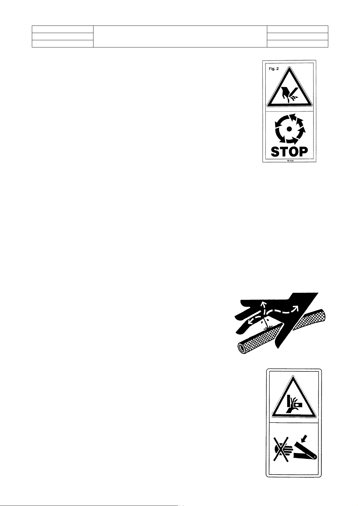
Do not enter the hazard area between
the header and the machine.
Safety instructions
0401
Never put your hands in the
auger while it is still turning.
Do not access the intake parts of the
implement before the power system has cut
out, the engine has stopped and the ignition
key has been removed.
Page 10
Chapter 1
p
Point 1.3 Point 1.3
0401
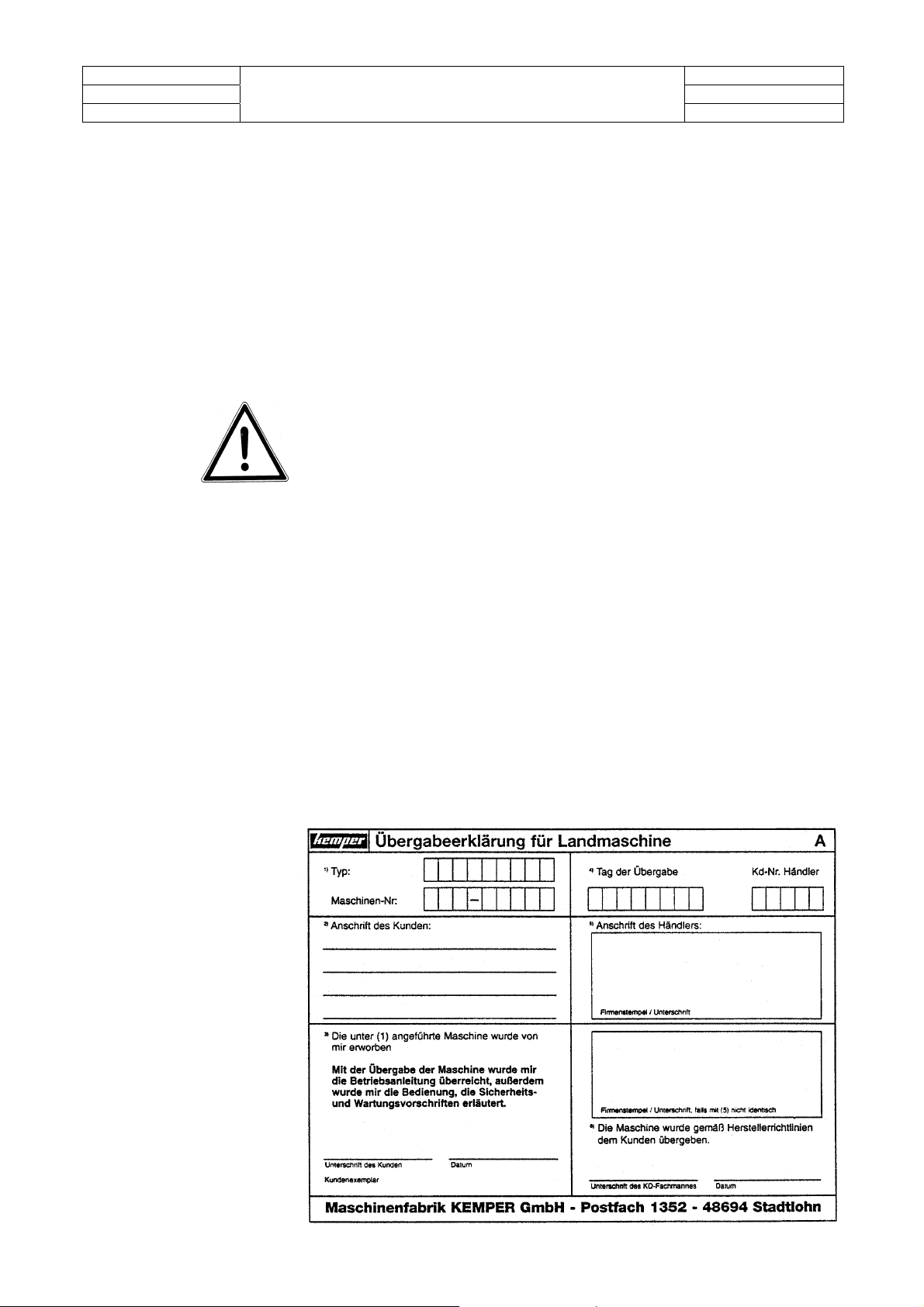
Do not touch any moving
Safety instructions
Chapter 1
0401
arts.
Beware of pressurised
fluids emitted from the
system!
Never place your hands in areas where
there is a crush hazard while it is still
possible for parts to move.
Page 11

Chapter 1 Chapter 1
Point 1.4 Point 1.4
0401
1.4
Accident
prevention
regulations
It is forbidden to stand or walk in the crop intake area.
Do not feed crop into the harvester using your hands. Do not
push crop further into the machine using your foot.
Exercise great care when connecting the jointed shafts.
The jointed shaft guard must be kept in good condition at all
Safety instructions
0401
times and the protecting tube must be secured against rotating.
Do not alter the number of fins on the protection on the jointed
shafts.
If necessary, attach counterweights in order to make the tractor
easier to steer, but be sure to observe maximum permitted axle
loads. Adhere to the stipulations made in the individual typeapproval or in the government inspection survey regulations.
Headers should only be detached and removed when the
equipment is standing on a level surface.
Whenever performing any work on the harvester the PTO lever
must be switched to the "off" position; the tractor engine should
be switched off and the ignition key removed.
Caution: The blade rotors are still rotating even after the intake
drums have come to a standstill!
Before investigating the equipment for foreign bodies: Switch off
all drive units; switch off the engine, and allow all moving parts to
come to a complete standstill.
The equipment should be securely supported whenever any work
is carried out underneath the machine.
Ensure that all blades are fixed securely.
Before carrying out any work on the header:
"Wait until the blade rotors have come to a complete
standstill"
Page 12

Chapter 1 Chapter 1
Point 1.4/1.5/1.6 Point 1.4/1.5/1.6
0401
When travelling on the public highway:
Safety instructions
0401
Observe all stipulations made in the extended individual
type-approval (document 'ABE') regarding statutory
highway regulations.
Attach the folding accident protection guard with covers
to the header.
Attach all additional side lamps and indicators.
The additional dipped headlamps should be switched on
when travelling during hours of darkness.
The reflecting hazard warning plates on the accident
protection guard must be in good condition.
The header must be raised so that the front accident
protection guard is approx. 300 mm above the road
surface.
Government inspection survey regulations regarding axle
loads, permitted gross vehicle weights and rear-end
weights must be observed.
Moreover, the general specifications contained in the accident
protection regulations for machinery, equipment, tools, technical
equipment and vehicles issued by the agricultural professional
associations, UVV 3.1 to 3.11 must be observed.
A measurement of the noise level was carried out during the CE
test: max. noise level reaching the driver's ears, in conformity
with regulation 86/188/EWG; measured in accordance with ISO
5131 with the cab closed = 80.0 dB (A).
Only genuine Kemper replacement parts should be used.
1.5 Mechanical safety
Do not place your hands or any other objects inside the
equipment while during operation or while the harvester engine is
still running.
Before carrying out repair and maintenance work, the harvester
engine must be switched off and the ignition key removed.
Safety devices may only be removed in order to perform repair
and maintenance work.
The permitted gross loads, axle loads and tyre pressures must
not be exceeded.
The statutory regulations of the highway code must be observed
when travelling on public highways.
1.6 Safety
instructions
for attaching and
removing the
header
The header may only be removed on firm, level ground.
When removing the header, ensure it is standing securely.
You may only enter the space between the harvesting attachment
and the machine when the engine is switched off and when you
have ensured it is not possible for the machine to roll forwards or
backwards.
Page 13

Chapter 1 Chapter 1
Point 1.8 /1.9 Point 1.8/1.9
0401
1.9 Safety guidelines
when welding and
Hazard from electrical current
Use only welding equipment with electrics which are in
working with
flame
Do not carry out welding where there is an increased
Safety instructions
0401
perfect condition
electrical hazard
(welder standing on a surface which will conduct
electricity, welding in a constrained position, welding in
confined spaces...)
Hazard from optical and UV radiation
Use a face screen with sight glasses appropriate to the
welding procedure in question
(welding goggles, hand or head guard with appropriate
glasses).
Protect your body by wearing clothing appropriate to the
welding procedure.
Hazard from build-up of gases
When components are subjected to heat, layers of paint
and deposits of contamination contained on the
components may combust. This will result in the formation
of noxious vapours.
It is therefore essential that layers of paint and
contamination are removed before heat is applied to the
components in the area to be welded.
(Quite apart from the hazard involved, contamination will
cause faults in the weld bead.)
Weld bead faults will also occur when welding is carried
out where a draft is present (stream of protective gas is
blown away), or when moisture is present (hydrogen
entering the weld bead).
Hazard from heat
Remember that a large amount of heat is applied to the
material when welding, making the parts extremely hot.
Make sure no combustible material is located within your
work area. Wait until all hot tools and equipment have
cooled down before touching them.
Page 14
Chapter 2 Chapter 2
Point 2.0/2.1/2.2 Point 2.0/2.1/2.2
0401
2.0 Declaration of
EC conformity
This product has been tested and marked in accordance with EU
directive 98/37/EC (Communauté européenne / European
Community). A 'Declaration of EC Conformity' is attached to the
Product liability
0401
instruction and should be delivered to the end-customer together
with the instruction.
2.1 Transfer of
ownership of the
equipment
Important! If the customer himself transfers ownership of the
equipment to another party at a later date, the instruction must
also be included in the transfer.
2.2 Obligation to
provide
information about
product liability
Product liability obliges the manufacturer and dealer to deliver the
instruction when equipment is sold and to instruct the customer in the
use of the equipment, referring to relevant operating, safety and
maintenance regulations.
A multi-copy form (A,B,C), as shown below, is attached to every copy
of the instruction. Written confirmation is required as proof of the fact
that the equipment and the instruction manual have been properly
delivered.
To this end, Document A must be signed and returned to Kemper.
Document B is retained by the dealer supplying the equipment, and
Document C is retained by the customer. This also ensure your
warranty rights.
Page 15
Chapter 4 Chapter 4
Point 4 Point 4
0401
4 General
Our patented cutting system enables you to approach the maize stems
from any direction you choose: parallel to the rows, perpendicular to the
rows, or at an angle.
Every single maize stem is fed automatically into a gap in the cutting
head.
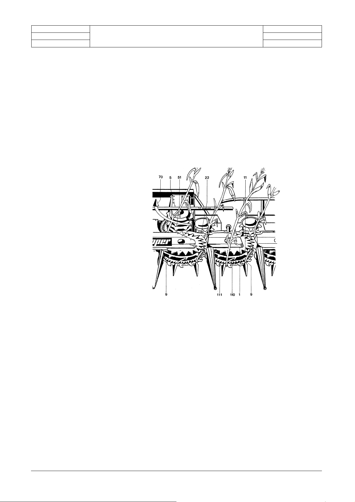
In open-cut mode, i.e. without return cut, the crop stem is cut along the
entire working width by the fast-action blade 9. The slow-action intake
drum 1 feeds the stem along the intake bars 110.
A row of teeth 111 grasp the stem securely.
The forward movement of the intake drum pushes the crop up against
the carrier teeth 11, thus allowing the crop to be transported safely past
the guides and scrapers 22 to the intake drum.
Here, the stem is placed against the carrier teeth 51 and is thus cleanly
and evenly gathered lengthways. It is then fed pre-pressed to the
header's pre-compression and intake rollers.
General
0401
Closely spaced rows - High crop yields
Maize cultivation methods have formed the subject of intensive debate
in recent times; there has also been a shift towards increasing crop
yields by placing the individual plants closer together.
However, if this new cultivation method is to be adopted, it is essential
that the existing seed drills be used, and harvest is only possible with a
row-independent harvesting system.
The new cultivation method does not allow us to work with double rows;
instead, the previous row distance of 75 cm must be reduced to 30 cm.
Maintaining the same cultivation density of 10 plants/m
greater distance between the plants in the individual rows.
The advantages of the new cultivation method:
■ More space for each individual plant.
■ Faster overgrowing between rows and hence earlier shading of soil.
■ Less soil erosion.
■ Improved utilisation of nitrogen in the soil.
■ Increased yields by approx. 12 - 17 %.
■ Improved quality.
2
produces a
Page 16
Chapter 4 Chapter 4
Point 4.1 Point 4.1
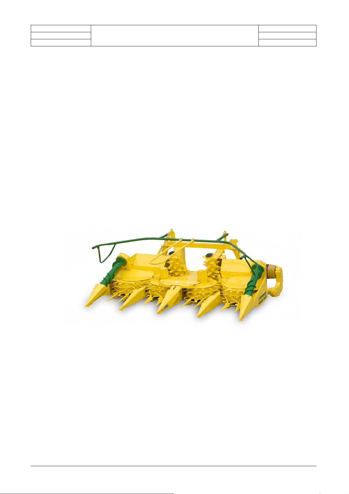
4.1 Description of
0401
the header
Harvesting implement with integrated interface for self-propelled
forage harvesters.
When fitted with the appropriate interface, the header is suitable
for attachment to a variety of self-propelled forage harvesters.
Power transmission is delivered by the SPFH drive line via oilimmersed transmission and safety clutches.
Row-independent cutting system with fast-running rotors and
freewheel mechanism.
Cutting across the entire working width by closed saw-type rotor
blades with replaceable segments.
Even crop intake to the chopping unit via slow-running intake
drums and clean gathering by two slanting intake drums. Two
mechanically driven crop separators for heavily laid crops, heightadjustable crop lifters.
General
0401
330
Working width = 3.0 m
Page 17
Chapter 4 Chapter 4
Point 4.2 Point 4.2
0401
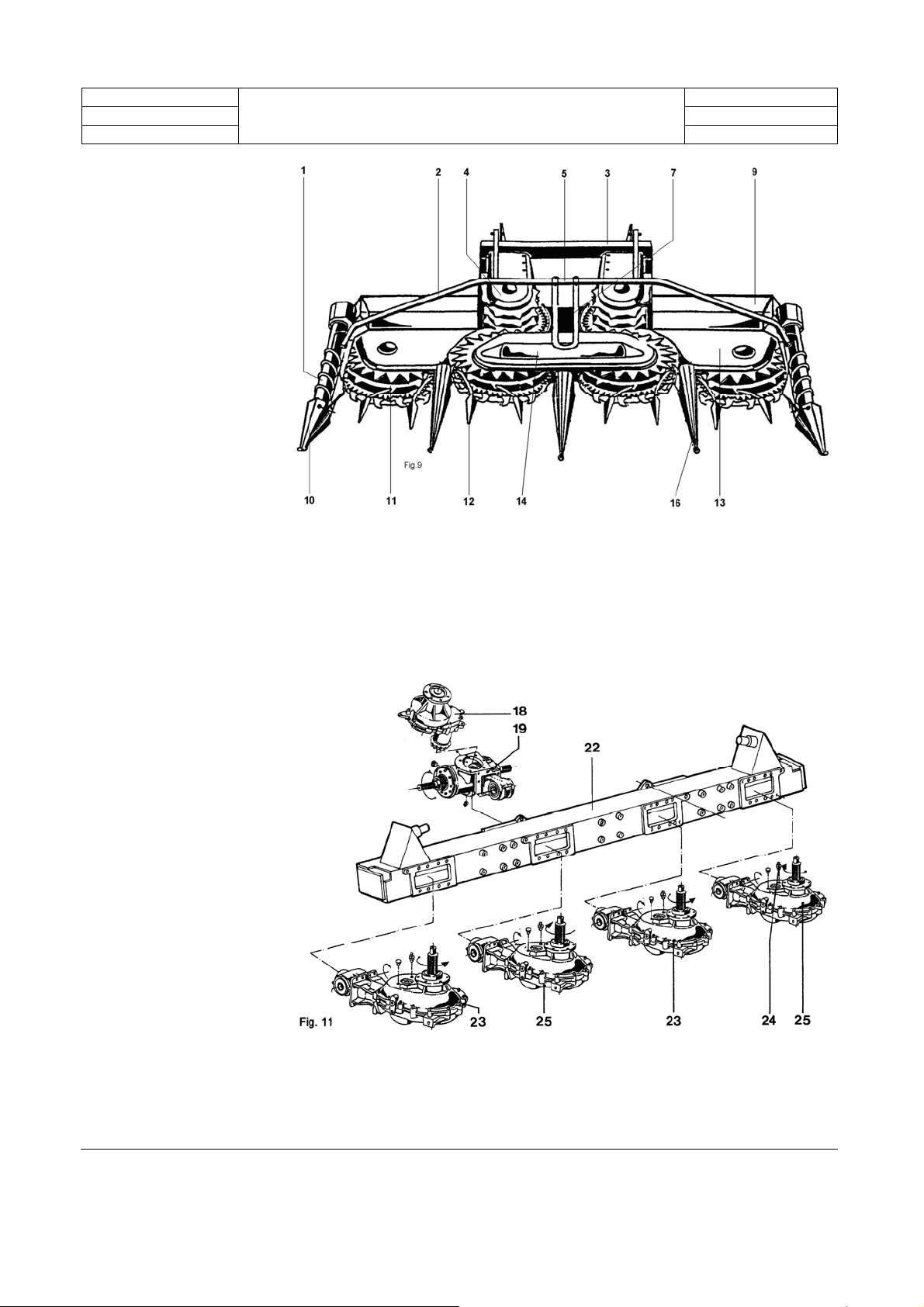
4.2
Design of the
General
0401
harvesting
attachments
with the major
sub-assemblies
Page 18

Chapter 4 Chapter 4
Point 4.2 Point 4.2
0401
Sub-assembly designations
1 Rotating lodged maize auger
2 Outer feed bar
3 Frame
4 Intake drum
5 Central feed bar
7 Centre guide
9 Rear guard
10 Outer crop separator
11 Intake drum, left or right-rotating
12 Small crop separators
13 Shield
14 Central covering plate
16 Large crop separators
18 Spur gear drives - Intake drum
19 Spur gear angle drive left and right
22 Basic frame
23 Spur gear angle drive - Intake drum, left-rotating.
24 Breather - always outside!
25 Spur gear angle drive - Intake drum, right-rotating.
General
0401
Page 19

Chapter 4 Chapter 4
Point 4.3 Point 4.3
0401
4.3 Header
dimensions and
weights
Length
Overall width
Height
Working width
Transport width
Weight of basic version
Height folded in - lowered
4.4 Maintenance
and testing
Maintenance at start of new season
The most important job to be performed before operating the header
General
Unit of
dimensio
n
m
m
m
m
m
Kg
m
0401
Harvester attachment type
330
2.06
3.00
1.36
3.00
3.00
1500
1.36
is to inspect the two friction clutches in the main power unit: remove
both clutches, dismantle, clean or replace.
(See appropriate instructions in the instruction manual)
Before commencing new operation, we recommend star ratchets K 43
in the intake drums be inspected. For lubrication of the star ratchet (1
x year) we recommend a lithium saponified grease, "GLEITMO 805
and 810" made by Gleitmolybdän. This is particularly suitable for
combating frictional corrosion.
Run the machine and check all bearings for overheating or excess
play.
Daily maintenance
Make sure scrapers (2 per rotor) beneath the rotor blade are intact.
This is important as blunt or deformed scrapers can cause blockages
and place an unnecessary strain on the power unit and friction
clutches.
Tighten the bolts after a few days' use when applying from new or
when replacing the blades or scrapers. Check all rotor blades. Heavily
worn blades should be replaced as they will create long stubble and
place unnecessary strain on the power unit.
The entire area surrounding the intake drums, rotor blades and
scraper must be cleaned of husks and stem remains every day.
Carry out a visual check of all transmissions every day to see if there
are any oil leaks.
Carrying out lubrication daily in accordance with the lubrication
schedule merely means greasing the two front bearings on the side
lodged maize augers, or, on certain models, greasing the jointed
shaft.
Weekly maintenance
All bolts and screws should be checked at regular intervals to ensure
they are firmly secured.
Foreign bodies in the cutting area can cause damage to or
deformation of the rotors, the carrier elements on the intake drums or
the crop separators. You should therefore check the entire area.
Page 20

Chapter 4 Chapter 4
Point 4.3 Point 4.3
0401
General
0401
4.5 Torques for
metric bolts
TORQUES FOR METRIC BOLTS in NM
Size
M6 4.8 6 9 11 13 17 15 19
M8 12 15 22 28 32 40 37 47
M10 23 29 43 55 63 80 75 95
M12 40 50 75 95 110 140 130 165
M14 63 80 120 150 175 225 205 60
M16 100 125 190 240 275 350 320 400
M18 135 175 260 330 375 475 440 560
M20 190 240 375 475 530 675 625 800
M22 260 330 510 650 725 925 850 1075
M24 330 425 650 825 925 1150 1075 1350
M27 490 625 950 1200 1350 1700 1600 2000
M30 675 850 1300 1650 1850 2300 2150 2700
M33 900 1150 1750 2200 2500 3150 2900 3700
M36 1150 1450 2250 2850 3200 4050 3750 4750
*“Lubricated“ means that the bolts are supplied with a lubricant such as engine oil, or that
phosphated or oiled bolts are used. "Dry“ means that normal or galvanised bolts without
any lubrication are used.
The torques specified in the table are guidelines only and do NOT apply
Grade 4.8 Grade 8.8 or 9.8
Lubricated
*
Nm Nm Nm Nm Nm Nm Nm Nm
Dry*
Lubrica-
*
ted
Dry* Lubricated* Dry*
Grade 10.9
where a different torque specification is given in this manual for certain
bolts and nuts.
Check that bolts and nuts are securely tightened.
Shearing bolts are designed to shear off when a specific load is applied.
Same grade bolts only should be used when replacing shearing bolts.
When replacing bolts and nuts, ensure that same grade parts or better
are used. Bolts and nuts of a higher grade should be tightened to the
same torque as the parts originally used.
Make sure that the threads engage properly and the bolts are correctly
applied.
This will prevent damage occurring when tightening.
Tighten locknuts (not the bolts) with a plastic insert and flanged steel
locknuts to approx. 50% of the 'dry' value given in the above table.
Tighten hinge / nuts to the full torque value.
Grade 12.9
Lubricated
*
Dry*
Page 21

Chapter 4 Chapter 4
Point 4.6 Point 4.6
0401
General
0401
4.6 Transporting the
equipment
Fold in the outer cutting units for transport (transport width 3.00 m)
Attach the folding accident prevention guard.
(The transport guard is fitted with flashing lights and position
lights.)
When folded, the cutting units may partially cover the headlamps
on some self-propelled forage harvesters.
In this case, it may be necessary to re-position the headlamps to
conform to the prevailing highway regulations, or to fit additional
headlamps.
When loading the equipment with the outer units folded, chains (or
rope) must be used as shown in Fig.7. This will prevent the
machine from toppling over. When loading in this way, you must
exercise great care and use additional securing chains if
necessary.
Fig.
7
Page 22

Chapter 4 Chapter 4
Point 4.7 Point 4.7
0401
4.7 Travelling on
the public
highway
Steering
To ensure proper steering is maintained, the steering axle on the
transport vehicle must be equipped with counterweights, paying
General
0401
due attention to the permitted axle loads.
Counterweight specifications are given in the appropriate
government inspection survey regulations.
Accident prevention
When travelling on public highways the entire area around the crop
separators must be covered with a folding guard.
Assembly sequence:
A After the rotors have come to a complete standstill, fold up
the side cutting units.
B Place the folding guard in a central position and insert the
rubber rings.
C Fold up the protective profiles on the side and insert rubber
rings.
D The runners, blades and other edges are covered with
protective cloths.
Ground clearance
When travelling on public highways the harvesting attachment
must be raised so that the front accident prevention device is
approx. 300 mm above the road surface.
Side lamps and indicators
As the side lamps and indicators on the transport vehicle are
usually covered by the intake drums in raised position, we have
mounted duplicates of these inside the accident protection device.
For the 12 V power supply a 7-pole plug is located on the right side
of the harvester.
Dipped headlamps Fig. 46 Fig. 48
The dipped headlamps (not to be confused with working
headlamps) must be duplicated at another position on the
harvester. This is because the road ahead is not adequately
illuminated when the outside intake drums are in the raised
position.
The TÜV, Germany's technical inspection authority, suggests the
following:
"Additional dipped headlamps "A" of approved design fitted (e.g.
Hella type 1 AB 004231-001, test mark HR HC/R E1 02 24461
R20) with two independent switches, for serial lighting when
travelling without the header and with standard cutting unit and
standard lighting plus additional headlamps when travelling with
Kemper harvesting implement.
The headlamp mountings are attached to the cab posts on the left
and right using appropriate drilled holes. The lower edge of the
headlamp should be approx. 3000 mm above the road surface".
See instructions in the appropriate government inspection survey
regulations.
Moreover, additional side indicators "B" should be mounted at the
front of the harvester on the right and left, in accordance with
statutory traffic regulations.
(e.g. Hella type 2 BM 006 692 - 011 or - 021)
Page 23

Chapter 4 Chapter 4
Point 4.7 Point 4.7
0401
General
0401
Page 24

Chapter 4 Chapter 4
Point 4.10 Point 4.10
0401
General
0401
4.10 Observe Public Road Legislation
CAUTION: Before transporting the machine on public roads, make
sure that the machine conforms to the legislation governing the use
of agricultural vehicles on the road.
Page 25

Chapter 9 Chapter 9
Point 9.0/9.1 Point 9.0/9.1
0501
9
Power transmission
Power transmission
Power is transmitted via jointed shafts, drive shafts and
transmission units.
0501
The individual oil levels have to be checked before
Initial start - up
9.1
Arrangement of
transmissions
330
the initial startup of the device. The header also
has to be subjected to a visual inspection.
How the drive elements interact
The harvesting implement is driven by jointed shafts from
the main chopping unit to the main drives (21 / 22) on the
implement.
The transmissions (20) for the transverse intake drums are
flanged directly to these transmissions.
Page 26

Chapter 9 Chapter 9
Point 9.1 Point 9.1
0401
Fig.
no.
20 Spur gear
21 Spur gear angle drive left
22 Spur gear angle drive right
Description
This gear is fitted with a ratchet clutch. It is filled with 0.5 l of
AVIATICON XRF liquid grease.
Transmission oil: 1.0 litres SAE 90
Transmission oil: 1.0 litres SAE 90
Power transmission
0401
Remarks
Before installing, we recommend you check the direction of
rotation. This is determined by the position of the rear bevel
gear shaft 100. On left-handed transmissions the bevel gear is
on the left. The bore in the bevel gear has one short and one
long projection to the hex form. The bevel gear is situated on
the short projection side.
Transmissions 1,5,6 and 7 = Freewheel for clockwise
Transmissions 2,3,4 and 8 = Freewheel for anticlockwise
Transmission 20 = Ratchet clutch 1150-1250 Nm
Page 27

Chapter 9 Chapter 9
Point 9.1 Point 9.1
Arrangement of
0401
Power transmission
0401
transmissions
330
Fig. 2
Page 28

A
Chapter 9 Chapter 9
Point 9.1 Point 9.1
0401
Direction of rotation
Power transmission
0401
When carrying out assembly and dismantling work on spur
gear angle drives 3-6 it is particularly important that you
observe the direction of rotation.
Freewheel
There are transmissions with anti-clockwise freewheel
and clockwise freewheel. (The number depends on the
type of harvesting implement.)
Basic principle: All transmissions have a fixing bolt
V M12x1.5 DIN 908
and a bleeding bolt E M12x1.5.
"The bleeding bolt is always assembled in the
direction of travel, facing outwards."
In the event of incorrect assembly, oil will escape from
the breather in the raised position!
There are essentially just 2 transmission versions:
Clockwise and
anticlockwise
transmission
L = anti-clockwise freewheel, transmissions items 4 ,6
R = clockwise freewheel, transmission items 3, 5
versions
Oil
The transmissions each have one oil supply system =
4.80 litres SAE 90.
n inspection screw P is located on the left and right
M22x1.5 and a magnetic drain bolt A M18x1.5 is located
at the bottom.
The threads are different to prevent confusion. Drain oil
Direction of rotation
before dismantling the transmissions 12 - 18!
We recommend you check the direction of rotation before
installing. This is determined by the position of the rear
bevel gear 190. On left-handed transmissions the bevel
gear is on the right. The bore in the bevel gear shaft has
one short and one long projection to the hex form. This
bevel gear is on the short projection side.
An additional mark is located on the raised casing area of
transmission 9: L or R at the top.
When assembling from new:
L, top = anti-clockwise transmission.
Split transmissions,
rear
R, top = clockwise transmission.
Transmissions 3-6 can be split to make for fast dismantling
in the event of service being necessary. The rear bevel
gear 9 remains in the basic frame.
Page 29

Chapter 9 Chapter 9
Point 9.1 Point 9.1
0401
Oil change intervals
Power transmission
First oil change after approx. 100 operating
hours, then every 500 operating hours
0401
Oil level check
Before checking the oil level, place the implement in a
horizontal position and open the check bolt.
Oil should reach the lower edge of the inspection aperture.
Transmissions with
grease lubrication
Item 20 = Spur gears. These two transmissions are each
filled with 0.65 litre of Aviaticon XRF liquid grease and are
lubricated for their entire service life.
Alternative grease options: Gresanat X00 made by
Westfalen or to norm: sodium transmission grease of
consistency grade NL GI 00, e.g. Shell special transmission
grease "H".
Transmission grease
- A comparison
Check interval
Made by Description
Westfalen Gresanat X00
Aral Aralub FDP 00
Shell Special transmission
grease
Esso Liquid transmission
grease
BP Energrease HT 00 EP
Texaco Starfak E 900
Antar Liquid transmission
grease
Daily visual check for oil leaks
H
EPEXELF 00
Page 30

Chapter 9 Chapter 9
Point 9.2 Point 9.2
0401
9.2
Position of openings
on the various
transmissions
Power transmission
0401
Filling, drainage bleeding bolts, grease nipples
A = Oil drainage bolt
E = Filler bolt
L = Bleed
N = Grease nipple
P = Oil level check bolt
Fig. 4
Page 31

Chapter 9 Chapter 9
Point 9.2 Point 9.2
0401
Power transmission
0401
9.3
Oil grade
Capacities, oil-filled
transmissions
Oil grades and capacities
SAE 90 transmission oil
Item 21 = Spur gear angle drive = 1.00 litre
Item 22 = Spur gear angle drive = 1.00 litre
Item 24 = Spur gear angle drive = 4.80 litres
Page 32

Chapter 9 Chapter 9
Point 9.3 Point 9.3
9.3 Oil grades and
0401
Power transmission
0401
capacities
Direction of rotation
When carrying out assembly and dismantling work on Spur
gear angle drive 4 it is particularly important that you
observe the direction of rotation.
We recommend you check the direction of rotation before
installing. This is determined by the position of the rear bevel
gear 100. On left-handed transmissions the bevel gear is on
the right. The bore in the bevel gear shaft has one short and
one long projection to the hex form. This bevel gear is on the
short projection side.
Ratchet clutch
Transmission 20 = Ratchet clutch
1150-1250 Nm
Transmission 24 = Ratchet clutch
570- 630 Nm
Fig.4
Description
no.
20 Spur gear drives 2
21 Spur gear angle drives Left-handed 1
Transmission oil: 1.0 L SAE 90
22 Spur gear angle drives Right-handed 1
Transmission oil: 1.0 L SAE 90
23 Spur gear angle drives Right-handed 2
Transmission for transverse intake drum - left-handed.
24 Spur gear angle drives Left-handed 2
Transmission for transverse intake drum - right-handed.
This gear is fitted with a ratchet clutch. It is filled with 0.5 l
of AVIATICON XRF liquid grease.
This transmission is fitted with a ratchet clutch.
Mark beneath transmission = 07
Transmission oil: 0.85 L SAE 90
This transmission is fitted with a ratchet clutch.
Mark beneath transmission = 08
Transmission oil: 0.85 L SAE 90
Parts
330
Remarks
Page 33

Chapter 9 Chapter 9
Point 9.4 Point 9.4
9.4
0401
Power transmission
0401
Basic machine lubrication schedule
Basic machine
Grease daily
1 = Grease nipple on lower bearing of
lodged maize auger
(left and right)
Grease annually
2 = Star ratchet in all eight intake drums.
We recommend lubrication using a lithium saponified
grease lithium-saponified grease
"GLEITMO 805 and 810" made by Gleitmolybdän.
This is particularly good against friction corrosion.
Page 34

Chapter 10 Chapter 10
Point 10.0 Point 10.0
0401
10 Clutches
Clutches
0401
General inspection of friction clutches
shortly before each new season begins
Page 35

Chapter 10 Chapter 10
Point 10.1 Point 10.1
0401
10.1 Starting clutch
Clutches
0401
800 Nm
Page 36

Chapter 10 Chapter 10
Point 10.1 Point 10.1
0401
The 700 Nm friction clutch in main drive
Clutches
0401
Protective
function
Fig. 55-58
The two friction clutches 50 in the main drive (beneath the
attachment frame) protect the entire machine from unnecessary
loads. Proper maintenance of both clutches and continuous
inspection of proper functioning are
absolutely essential!
Torque The torque setting is M = 800 Nm. The following two chapters
describe the maintenance work necessary to ensure this torque
value is retained. The friction clutch must be "bled" at regular
intervals.
Failure to observe these instructions will render your warranty
null and void!
Simple
inspection
Simple inspection before first time of using and following a
lengthy period out of service:
■ Dismantle protective tube 54.
■ Tighten nuts 12, thus relieving the friction disk,
slip clutch.
■ Loosen nuts 12 to end of thread.
■ Assemble protective tube.
General
Inspection
"bleeding"
General inspection before start of new season:
■ Dismantle protective tube 54 - Dismantle circlip 52 Push aside bushing 51 -
Remove clutch shaft 53 - Remove both friction clutches 50.
■ Tighten nuts 12, thus relieving friction disks 4 and setting ring
2.
■ Remove setting ring 2.
■ Remove spring pack, friction disks, drive plates and hub,
clean or replace if necessary.
In order to maintain torque at M = 800 Nm, the correct
installation of setting ring 2 is important, see Fig. 55
(cam 9 on setting ring 2 inside - cam 9 engages in
depression 1 on housing 8).
New linings When new friction disks have been fitted, the clutch will require
time to run-in before it achieves full torque.
■ Exercise care when driving off. Do not place the clutch under
unnecessary load.
■ Allow a running-in period before driving at full power.
Note on
assembly:
It is easier to assemble the friction clutch if all the nuts 12 are
tightened. Meshing on the clutch housing and the flange hub can
then be turned.
Page 37

Chapter 10 Chapter 10
Point 10.4 Point 10.4
0401
10.4 Dismantling
Clutches
0401
Page 38

Chapter 11 Chapter 11
Point 11.0 Point 11.0
0401
11
Pre-season
maintenance
Maintenance and inspection
The 'general inspection' of the two friction clutches in the
main drive is the most important task before commencing
Maintenance
0401
operation with the harvesting implement: remove the two
clutches, dismantle them, clean and replace if necessary.
Follow the instructions contained in the chapter "Friction
clutch in the main drive".
Before commencing operation at the start of a new season,
we also recommend the inspection of the star ratchets K 43
in the gathering drums. We recommend the use of a lithiumsaponified grease "GLEITMO 805 and 810" made by
Gleitmolybdän for lubrication of the star ratchet (1 x
annually); this is particularly effective against friction
corrosion.
With the machine running, check all bearings for overheating
and for excess clearance.
Daily maintenance
Make sure the scrapers (2 per rotor) beneath the blades are
intact, as blunt or bent scrapers will cause blockages and
place unnecessary load on the drive system and the friction
clutches.
After a few days' operation or when replacing the blades or
scrapers, the bolts should be re-tightened. Check all the
blades. Replace heavily worn blades, as these will cause
long stubble and place the drive system under unnecessary
load.
The entire area around the gathering drums, the blades and
scrapers must be cleared of husks and stem remnants on a
daily basis.
You should carry out a daily visual inspection of all
transmissions and check for oil leakage.
'Grease daily in accordance with lubrication schedule' simply
means you must grease the two front bearings on the side
lodged maize auger, or the jointed shaft on certain models.
Loose bolts on the blades and scrapers will quickly result in
major subsequent damage such as worn bores. A brief
inspection with the side cutting units raised takes very little
time.
Weekly maintenance
You should check regularly that all screws and bolts are
properly tightened. Torques in Nm:
Foreign bodies in the cutting area can cause damage or
deformations to the blades, the drives on the gathering drum
or on the crop separators. It is therefore essential that you
check the entire area.
Clean the clutches in the hinge.
Page 39

Chapter 11 Chapter 11
Point 11.0 Point 11.0
0401
Maintenance at the
end of the season
Clean and conserve before a lengthy period out of
service. Follow the instructions given on the equipment!
Maintenance
0401
Using high-pressure cleaner : water pressure max. 80 bar,
distance of nozzle from equipment min. 25 cm and water
temperature max. 50° C.
Important : Do not use jets with circular section!
Touch-in minor damage to paintwork immediately.
Clean all spaces 21 above the drum star ratchet K43.
Carry out the first transmission oil change after 100
operating hours, and then every 500 operating hours.
Grease in accordance with lubrication schedule.
Inspect all parts for general wear and tear and order
replacement parts in good time.
The use of replacement parts, accessories and additional
equipment which are not genuine KEMPER parts and have
not been tested and approved by KEMPER can have
negative effects on the design characteristics of the
KEMPER machine or impair its proper functioning, thus
impairing its active and/or passive safety when driving or
when working (accident prevention).
For any damage caused through the use of parts,
accessories and additional equipment which are not genuine
KEMPER parts, KEMPER declines all liability.
Page 40

Chapter 11 Chapter 11
Point 11.1 Point 11.1
0401
11.1
Star ratchet
Maintenance
0401
Information regarding
the star ratchet
The star ratchet as shown in Fig.85 can be removed by
removing the hex bolts S ( 8x ) without the need to
dismantle the gathering drum.
Page 41

Chapter 11 Chapter 11
Point 11.2 Point 11.2
0401
11.2
Blade wear
Blades
The blades have a limited service life. Fig. 94 shows:
Teeth 1 = New condition = 1:1
Teeth 2 = Condition after heavy duty
When the tips are fully worn, the crop may be pushed
forward. Cutting will then require greater power, which will
have a negative effect on the transmissions and clutches.
Maintenance
0401
Replacing the blades
When assembling the coated blades, you should ensure that
green and yellow blades are fitted alternately. Pay attention
to left and right rotation. The coating should face upwards.
The assembly sequence is a safety feature: when the rotor
is turning, a visual effect is created which shows that the
rotor is in operation.
Page 42

Chapter 11 Chapter 11
Point 11.3 Point 11.3
0401
11.3
Maintenance of the intake and cutting area
Maintenance
0401
Intake and cutting
area
The following functional parts are included in the intake and
cutting area:
Small crop separators T - Intake bars E
Driver teeth M - Row of teeth Z
Blades S - Blade scrapers SR
Rotor R - Rotor scrapers RR
The functional interaction of these parts is of major importance for
crop intake, for the safe grasping and cutting of the crop, and for
the further crop transport. Problems occurring in the cutting area
are usually easy to resolve, providing the following instructions
are observed.
Page 43

Chapter 11 Chapter 11
■
■
■
■
■
■
■
■
■
■
Point 11.3 Point 11.3
Small crop separators
0401
Fig. 93
The gap between the rear side of the small crop
separators T and the drive teeth M should be as small as
Maintenance
0401
possible (4-6 mm). The smaller the gap, the better lodged
crop will be picked up.
Drive teeth
For the reason mentioned above, please ensure that any
deformation of the drive teeth M, caused by the presence
of foreign bodies in the system, is rectified immediately.
Intake rods
The intake rods E perform the important task of pressing
the crop into the narrowly spaced row of teeth Z.
Wear to the intake rods E ( 18 ∅ ) can occur after a
lengthy period of use. This wear can be compensated for
by making re-adjustment; alternatively, the parts can be
replaced.
Blades
The blades must be assembled in the direction of cut.
The blades will continue to run after the harvesting
implement has been switched off. The different colour of
the blades provides a visual warning, and the clicking
sound made by the freewheels provides an audible
indication that the blades are still running.
Caution! Do not touch any parts while they are moving!
Wait until the rotors have first come to a complete
standstill.
Blade scrapers SR
Intact blade scrapers SR keep the cutting area free of
fowling by weeds and husks. They are secured on the rotor
by a fixing screw M 10 x 25 and a shearing screw M 8 x 25.
Both screws are special-type screws because of the degree
to which they are tightened ( 8.8 ).
Blunt or bent scrapers will cause blockages. We therefore
recommend they are inspected on a daily basis.
The tungsten carbide coating on the scrapers SR must
face forwards in the direction of rotation.
The two scrapers RR on each rotor keep the space between
rotor R and the transmission clear of husks and
contamination.
Rotor scrapers RR
Intact scrapers protect the drive system from overloading.
The front edge in the direction of rotation should be as
sharp as possible. We therefore recommend daily
inspection. By loosening the special nut 20 and
dismantling the blade scrapers SR, you can remove the
scraper RR and hone its leading edge using a right-angle
grinder.
Page 44

Chapter 11 Chapter 11
Point 11.4 Point 11.4
0401
Maintenance
0401
11.4
Inspecting the crop guide track
Page 45

Chapter 11 Chapter 11
Point 11.4 Point 11.4
0401
Scrapers and
guides
All the scrapers and guides inside the crop guide track require
special attention and should be carefully examined in the event of a
Maintenance
0401
fault occurring. Faults can occur (e.g.) when foreign bodies enter
this track.
Faults can also occur following assembly work in this area.
Should you notice any faults in the flow of the crop, you must
examine the entire scraper and guide track.
Scrapers 7
Fig.96
The basic setting is correct if all the teeth in the gathering drum 5
run through the centre of the slot.
The scraper ends A should also be as close as possible against the
wall of the gathering drum 5. The distance should not be greater
than 5 mm. The teeth on the gathering drum 5 should all pass at
the same height through the guide slot B.
Guide
Fig. 95
Here, too, two important points should be observed. The scraper
ends F should be set as close as possible to the wall of gathering
drum 6.
A maximum distance of 5 mm should not be exceeded.
The lower drive teeth G should not pass more than 4 mm away
from the guide plate.
Scraper 8
Fig.95
In connection with the intake plate 20, the scraper 8 can be turned
about the feed drum 9 depending on the channel width on the
harvester. You should ensure that the H are also set as close as
possible to the feed drum wall 9 (max. 5 mm distance).
Page 46

Chapter 11 Chapter 11
Point 11.5 Point 11.5
11.5
0401
Scrapers
Maintenance
0401
Scrapers
Fig. 98
Intake drum
Feed drum 9
Intake drum
Gathering
drum 6
The scrapers on the teeth of gathering drum 6 and feed drum 9
have the important task of keeping the scrapers 2,3,7 and 8 free
of husk accumulations.
Feed drum 9 is fitted with 5 scrapers.
The three rows of teeth on all the gathering drums are each fitted
with a scraper. One set of driver teeth M is also fitted with a
special flat scraper.
Fig.98
Page 47

Chapter 11 Chapter 11
Point 11.6 Point 11.6
0401
Inspection The scrapers are made of heavy-duty special steel. They are
11.6
subject to continuous wear and tear and should therefore be
inspected at regular intervals.
An accumulation of husks in the scrapers A is usually a sign of
incorrect adjustment or faulty scrapers.
Any wear of the cleaner points can be compensated by build-up
welding with steel electrodes.
Attachment frame
Maintenance
0401
Attachment
frame
Check for proper tightening of all screws after the first 10 hours of
service, and from then on at regular intervals.
When assembling the attachment frame 1, you should first tighten
the screws 14. Then tighten the screws on the struts 8 at top and
bottom.
Page 48

Chapter 11 Chapter 11
Point 11.7 Point 11.7
0401
11.7
Fault Possible cause Remedy
Fault - Causes
Heavy running cutting
rotors
Vibration of implement
Husks accumulate on
scrapers
Stubble is bent forwards
before it is cut Long stubble
Maintenance
Blunt blades Replace blades Greater power required
Faulty scrapers Replace scrapers
Blockage of leaves
beneath rotors
Contamination in rotor
area
Faulty scrapers Replace scrapers
Imbalance caused by
uneven blades
Scrapers torn off Replace scrapers
Imbalance caused by
contamination in rotor
Height at which blades
pass too great
Scrapers have moved See chapter
Small crop separators are
full of leaves
One scraper is torn off Replace both scrapers
Blunt blades Replace blades
0401
Clean rotor area daily
Clean rotor area
Replace blades in pairs
Clean rotor
Adjust – replace if
necessary
"maintenance and
inspection of scrapers"
Clean crop separators
Drives heat up
Intake drum or feed
drum stops
(Cutting rotor is running)
Intake drum and cutting
rotor stop
Entire right or left-hand
side stops
Backlog in hydraulic
system in outer folding
cutting unit
Faults upstream of precompression rollers
Too much oil in the drive Check oil level
Bunch or ball of crop
lodged in intake channel
Clutch transmits speed Repeat procedure if
Damage to drive Replace parts
Faulty claw clutch
(selector sleeve)
Left and right friction
clutch
Faulty (starting-off clutch)
Foreign bodies, e.g. grain
of sand in front of throttle.
Incorrect gear
combination
Springs on precompression rollers
incorrectly set
Reverse a short
distance
necessary
Replace faulty parts
See "Friction clutch in
main drive"
Clean throttle: located in
screwed joint at cylinder
input
Select new gear
combination in acc. with
table of cutting lengths.
Adjust:
Green maize = slacker
Dry maize = tighter
Page 49

Drum speed
40 – 44 min1−
38 - 44 min1−
48 - 52 min1−
Page 50

Starting
Driving into the
crop
fahren
Direction of travel
Driving speed
Turning
Changing the
forage wagon
Eliminating
problem
Working with the Harvesting Header
Starting – Turning – Changing Forage Wagon - Reversing
The header may only be used, serviced and repaired by
personnel familiar with the operation of the machine or trained and instructed
about the dangers and risks associated with the machine!
These instructions only serve to make some general recommendations. Your
experiences as well as compliance with the following instructi ons and
own
notes are certain help avoiding major problems.
• You should be familiar with the machine before you start!
Start the forage harvester, engage the chopping unit and the header as well as
reverse with the engine running at idling speed the engine running at idling
speed. Reversing causes the gathering drums to rotate in the opposite
direction. The cutting rotors stop. Switching the gathering drums to forward
movement should also take place at
of the friction clutches.
• Always start and shift into first at idling speed to save the
drive units!
When the chopping unit and the cutting blades have come up to speed, drive at
a sufficient speed into the crops to obtain from the beginning a compact stream
of fodder. This applies especially
handling short-stemmed maize.
• Always drive smoothly and steadily into the crops!
The row-independent harvesting system allows selection of any direction of
travel. In difficult conditions (e.g. down crops) there is always one direction
which provides better results. This must be determined by trial and error.
• Use the free choice of the travel direction for your advantage!
The driving speed is determined by the type and density/volume/mass of the
crops and the available engine power. The shorter the crop and the lower the
crop density, the faster you should drive to ensure satisfactory operation of the
gathering elements.
• The driving speed is based on the existing mass, the type of crops and the
harvester capacity.
• To protect the header drive, maintain your speed when turning and steadily
turn back into the crops when negotiating headlands.
• Maintain rpm when turning!
Due to the short conveyor distances of the header, it is not advantageous to
actuate the instantaneous stop at the forage harvester when changing the crop
wagon. Stopping and restarting the unit would only cause loss of time and
expose the drive units to unnecessary stresses.
• When changing the forage wagon, allow all drive units to continue to run!
To clear blockages in the channel openings caused by weed -infested crops or
long and sticky husks, stop and operate in reverse for a short period (idling
speed, repeat if necessary).
• It is important that the quick reversal process does not allow the cutting
blades to come to a stop!
Should you find it necessary to use your hands to remove any material, be sure
to switch off the combine harvester motor and turn the PTO shaft shift lever to
OFF.
Even though the gathering drum may have stopped rotating, the cutting blades
may still be rotating! Wait for all moving parts to come to a complete stop!
idling speed to avoid unnecessary slipping
in case of difficult crop conditions or when
Page 51

Down maize
Fig. 1
Fig. 2
Page 52

Down maize
Down crops vary widely, because the effects of nature differ greatly.
Despite the successful cultivation of new varieties and the use of new growing
methods, it will never be possible to overcome the problem of down crops. This is
why we have equipped the header with standard design features and technical
solutions, which allow contractors to offer a machine which can deal with any
situation. The most important requirement is here the row-independent operation
so that crops can be approached from the optimal side.
Standard equipment for the header consists of two driven maize augers for down
crops as well as height adjustable crop separators. With the aggressive toothed
element at the gathering drums, the stems frequently positioned crisscross on the
ground are pulled apart, lifted by the traverse auger for down crops and height
adjustable crop separators, and then safely rioted to the blades of the forage
harvester.
Here are some things to consider in spite of the standard universal equipment:
• Walk around the field to determine the best possible driving direction.
• In most cases, it is best to approach crops at a crosswise angle to the
• When starting the harvest, observe exactly how well the machine is handling
• Quickly drive at a very low rpm of the gathering drums into the crops so that
• In case of jams: stop, reverse briefly and repeat the process if necessary.
• Extensive reversing is usually always disadvantageous.
• Mount rigid stalk lifter (fig. 1, optional equipment); kit containing 4 lifters
330 = Sets of 2
Never use your hands or feet to "help"!
direction in which the stalks are positioned. See Fig. 2
the crops.
a material flow is created.
Renewable
resources
Ornamental
grasses
(Maiden Gras,
Zebra Gras,
Elephant Grass)
Always select a high forward speed to obtain an immediate flow of material when
harvesting short-stemmed maize. The feed bars also have to be lower so that the
maize stalks do not enter the compression rollers vertically.
• Drive quickly and apply more pre-pressure to the maize stalks.
The header is currently the only production machine which allows elephant grass
to be harvested and chopped in a single operation. The chopped crop has to
feature an even structure due to the subsequent further processing.
This is only possible with the unique lengthwise transport and bundling provided
by the header.
Page 53

Chapter 15 Chapter 15
Point 15 Point 15
0610
Attachment to forage harvester
0610
15 Attachment to forage harvester
Interface Rigid frame for firm attachment of header to harvester
Notes When attaching a header, always adhere to the following instructions:
• Slowly drive the forage harvester to the header.
• Attach the header to the pre-compression roller housing.
• Lift the header.
• Lock the support feet at the highest position.
• Ensure that the header is fully engaged in the receptacle so
that it cannot become dislodged.
• Close the locking mechanisms.
• Mount the safety devices.
For detailed mounting instructions, please refer to the
respective chapter in the section covering your forage harvester
model in this manual!
Page 54

Chapter 15 Chapter 15
Point 15 Point 15
0610
Attachment to forage harvester
0610
Removing header from forage harvester
.
2. 1.
1. Lower the header onto the level ground.
2. Pull out the two support feet and engage them.
3. Remove the jointed shaft.
4. Open the locking mechanism.
5. Disconnect the hydraulic hoses.
6. Slowly lower the mounting device of the forage harvester until
the frame is released and the harvester can be moved away
from the header.
7. Slowly drive the harvester away from the header.
Some header models require a third support foot below the centre
separator tip. For details, please refer to the section covering your
harvester model in this manual.
Page 55

Serial number The serial number identifying the harvesting header is engraved into
the type plate of the machine, which is attached at the position shown
below.
stamped number
Type plate Please enter here the serial number of your harvesting header.
 Loading...