

Page 1
M102A|Zweit-Akkulader6-24V/DC
Für Bleiakkus 6 bis 24 V. Mit dieser Akkuweiche werden 2
D
Akkus getrennt voneinander geladen an einer Ladestromquelle (Kfz Lichtmaschine, Solaranlagen, Windräder, Ladegeräte usw.). Für Ladeströme
bis max. 10 A (mit Kühlung 20 A). Der Ladestrom verteilt sich so, dass ein
leerer Akku stärker geladen wird als ein fast voller Akku. Ideal für Motorcaravans, wenn mit einem Akku Fernseher, Radio usw. betrieben werden
und der zweite Akku zum Starten des Motors voll bleiben muss. Oder für
Wochenendhäuser, wenn ein Akku für die Alarmanlage nicht leergemacht
werden darf.
Es kann ein Ausgleichsstrom von ca. 0,005 A ießen zwischen den beiden
Akkus (Im Normalbetrieb bei 12 V). Das dient dazu einem evtl. vorgeschalteten Solarregler die evtl. erforderliche Spannungskontrolle der Akkus zu ermöglichen.
M102A|Secondbatterycharger6-24V/DC
For lead accumulators 6 to 24 V. With this accumulator se-
GB
parating lter 2 accumulators are charged separately at one source of
charging current (vehicle generator, solar systems, windmills, chargers
etc). For charging currents up to 10 A at maximum (with cooling 20 A).
The charging current distributes in such a manner that an empty battery
will be charged more than an battery that is almost charged. It is perfect
for motor caravans if one battery operates the television, radio etc. and
the second battery must remain charged in order to start the motor. Or
for weekend cottages if one battery used for the alarm system must not
be emptied.
A compensating current of approx. 0.005 A may ow between both accumulators (during normal operation at 12 V). This serves the purpose to
enable a solar regulator, which is possibly connected in series the possibly
necessary voltage control.
M102A|Segundocargadordeacumuladores
6-24V/DC
E
Para acumuladores de plomo 6 a 24 V. Mediante este ltro de banda de
acumulador se cargan 2 acumuladores separado uno de otro a una fuente
de corriente de carga (dínamo de automóvil, instalaciones solares, ruedas
eólicas, cargadores, etc.). Para corrientes de carga hasta máx. 10 A (20
A con enfriamiento). La corriente de carga se distribuye de manera que
un acumulador vacío será cargado más que un acumulador casi pleno.
Ideal para caravanas de motor cuando se acciona el televisor, radio, etc.
con un acumulador y el segundo acumuador debe quedarse cargado para
arrancar el motor. O para casas para el n de semana cuando no se debe
vaciar un acumulador que se utiliza para el sistema de alarma.
Una corriente de compensación de aprox. 0,005 A puede uir entre ambos
acumuladores (durante el servicio normal a 12 V). Eso sirve para facilitar
un regulador solar eventualmente preconectado el control de la tensión de
los acumuladores que se necesita eventualmente.
M102A|Chargeurd’accumulateursecondaire
6-24V/DC
F
Pour les accumulateurs au plomb 6 à 24 V. Avec ce ltre de bande
d’accumulateur on peut charger 2 accumulateurs séparément à une source de courant de charge (génératrice d’automobile, installations solaires,
éoliennes, chargeurs de batterie, etc.). Pour les courants de charge jusqu’à
max. 10 A (avec refroidissement 20 A). Le courant de charge se partage de
sorte qu’un accumulateur vide soit chargé plus qu’un accumulateur qui est
presque plein. Idéal pour les caravanes à moteur si on veut actionner le téléviseur, la radio, etc. avec un accumulateur et le deuxième accumulateur
doit rester chargé pour mettre le moteur en marche. Ou pour les maisons
fermettes quand il ne faut pas décharger l’accumulateur qui est employé
pour l’alarme automatique.
Un courant compensateur d’env. 0,005 A peut couler entre les deux accumulateurs (pendant la marche normale à 12 V). Ceci a le but de faciliter
un régulateur solaire qui est monté en série éventuellement le contrôle de
voltage des accumulateurs éventuellement nécessaire.
M102A|Tweedeacculader6-24V/DC
Voor loodaccu‘s 6 tot 24 V. Met deze accu splitter worden
NL
2 accu‘s gescheiden van elkaar geladen, door de voedingsbron (zonnecellen, windmolen, lader etc.). Voor laadstromen tot max. 10 A (extra
koeling 20 A). De laadstroom verdeeld zich zo, dat een „lege“ accu sterker
geladen word dan een „volle“ accu. Ideaal voor campers, caravans als
een accu voor de TV/radio etc. gebruikt wordt, en de tweede accu voor
het starten van de motor “vol“ moet blijven, of bijvoorbeeld voor het
weekend-huis waar de accu van het alarm niet „leeg“ mag zijn.
Er kan aan de uitgang een gelijkstroom van ca. 0.005 A tussen beide
accu’s vloeien (bij 12 V gebruik). Dit is nodig voor sommige zonnecel
laadregelaars, die deze spanning controleren.
M102A|Segundo-carregadoracumulador
6-24V/DC
P
Para acumuladores de chumbo 6 até 24 V. Com esta linha do acumulador,
são 2 acumuladores separados um do outro carregados numa fonte de
corrente de carga (automóvel-dínamo de veículo, instalação solar, rodas
eálicas, carregadoras etc.) Para correntes de carga até máx, 10 A (com
refrigeração 20 A). A corrente de carga destribui-se assim, um acumulador vazio é carregado mais forte que um acumulador cheio. Ideal para
caravanas com motor, quando com um acumulador é exercido televisão,
rádio etc., e o segundo deve car cheio para pôr em marcha o motor. Ou
para casas de m-de-semana, quando um acumulador para instalação de
alarme não pode estar vazio.
Entre os dois acumuladores pode correr uma corrente de compensação de
cerca de 0,005 A (Em serviço normal a 12 V). Isso serve talvez a controlar
a tensão dos acumuladores que tem um regulador solar pré -engatado.
M102A|Зарядноеустройстводля
двухаккумуляторов6-24Вольт
RUS
Устройство предназначено для зарядки свинцовых аккумуляторов от
6 до 24 Вольт. При помощи данного устройства можно одновременно
заряжать два различных аккумулятора от одного источника питания
(от автомобильного генератора света, от световых установок, от
ветроколес, от одного зарядного устройства, и т. д.). Устройство
расчитано на ток зарядки макс. 10 А (с охлаждением 20 А). Ток
зарядки распределяется таким образом, что полностью разряженый
аккумулятор получает больше тока зарядки, чем второй почти
полностью заряженный. Устройство идеально подходит для
использования в жилых автоприцепах, когда один аккумулятор
используется для питания телевизора, радиоприемника и т.д. а
другой для запуска автомобиля. А также данный прибор можно
использовать на дачах с сигнализацией, где аккумулятор для питания
сигнализации не должен оставаться разряженным.
Между двумя аккумуляторами может течь компенсирующий ток
примерно 0,005 А (В нормальном режиме работы при 12 В). Это
необходимо для возможности подключения солнечных регуляторов
с контролем напряжения на аккумуляторах.
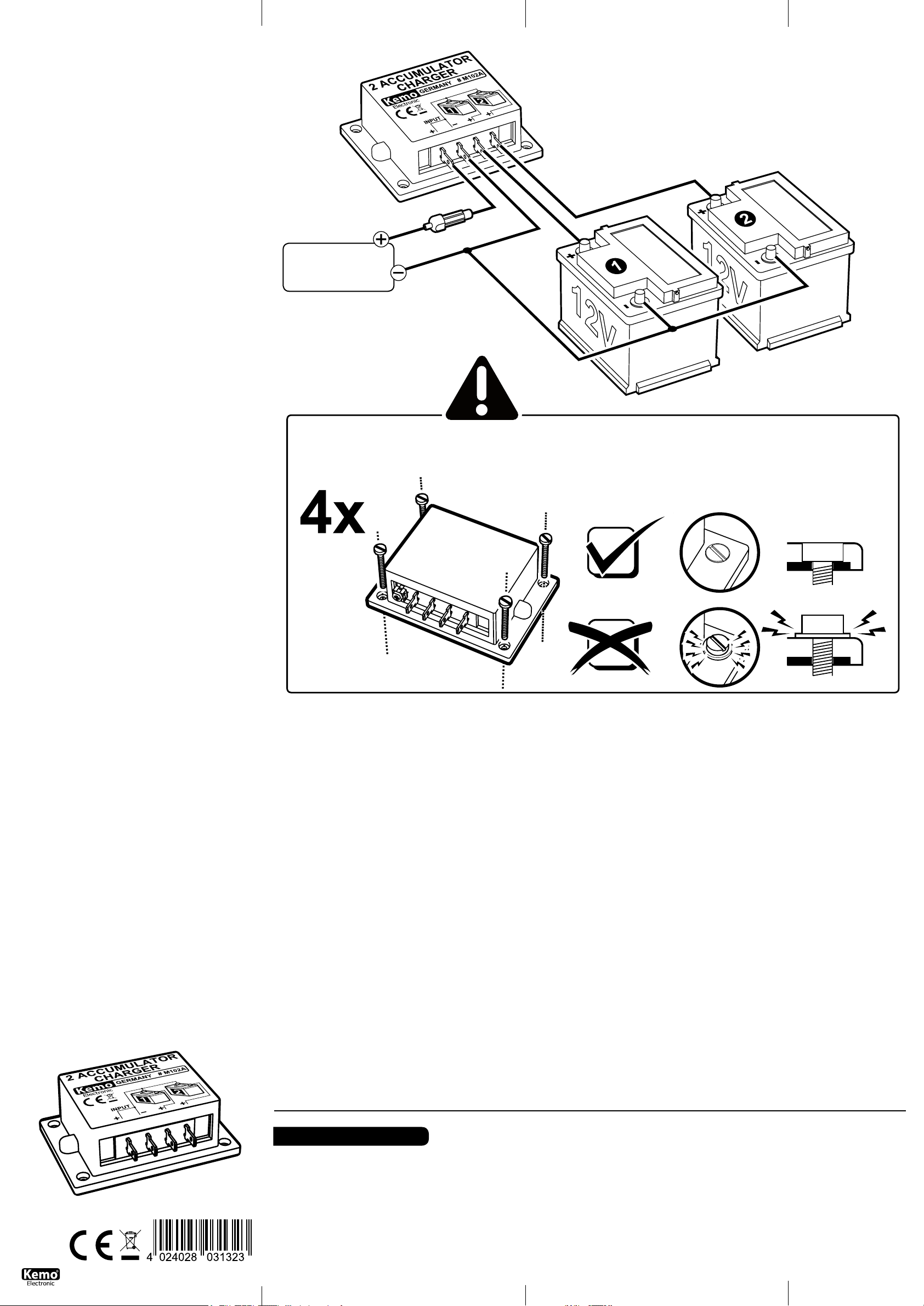
ANSCHLUSSPLAN|CONNECTINGPLAN
• EingangLadespannung
(vom Laderegler)
• Inputchargingvoltage
(from charging regulator)
D| Wichtig!Die Alu-Grundplatte darf keinen mechanischen Spannungen ausgesetzt
werden (keine Löcher bohren, nicht auf unebene Kühläche schrauben usw.). Auf der
Innenseite der Alu-Grundplatte sind direkt anliegend empndliche elektronische Bauteile
montiert, die bei mechanischen Bewegungen defekt werden und das Modul dann nicht
mehr arbeitet!
D|WichtigeMontagehinweise,bittebeachten!
Je nach Belastung kann sich das Modul mehr oder weniger erwärmen. Die Wärme entsteht an der AluPlatte am Boden des Moduls und muss gemäß Einbauanleitung unter bestimmten Umständen durch die
Montage auf eine Kühläche gekühlt werden.
Dabei ist es wichtig, dass das Modul mit 4 Schrauben M3 oder Blechschrauben 2,9 mm plan auf ein kühlendes, planes Kühlblech montiert wird. Das kann auch die Rückwand eines Metallgehäuses sein. Wichtig
ist, dass sich die Alu-Unterseite des Moduls dabei nicht verzieht! Sie dürfen also keine größeren Schrauben
nehmen und die Löcher am Modul aufbohren. Die Schraubenköpfe müssen auf dem Blech des Moduls
auiegen und nicht auf dem Plastikrand des Moduls! Bei der Montage darf sich das Modul auch nicht
verziehen (wenn der Untergrund nicht plan ist). Der Grund: Auf der Innenseite der Alu-Bodens des Moduls
sind über einer dünnen Isolierschicht direkt die elektronischen SMD-Bauelemente aufgelötet und wenn
sich der Aluboden des Moduls verzieht, lösen sich die Lötstellen und das Modul geht defekt. Bitte achten
Sie auch darauf, dass die in der Beschreibung als maximal angegebene Temperatur der Bodenplatte nicht
überschritten wird! Ansonsten muss eine größere Kühlplatte angeschraubt werden!
GB|Importantinstallationinstructions,pleasenote!
Depending on the load the module heats up. The heat is dissipated from the aluminum plate at the bottom
of the module. Under certain circumstances it must be mounted on a cooling surface according to installation instructions. It is important that the module is xed with 4 M3 screws (or 2.9 mm metal screws) on
the cooling surface. This may be the back wall of a metal casing. The aluminum plate on the bottom of the
module must not bend, do not use larger screws and do not drill larger holes. The screw heads must rest
on the plate of the module, rather than on the plastic edge of the module! During assembly, the module
should not be curled up (if the ground is not at). The reason: on the inside of the aluminum base of
the module the thin insulating layer are directly soldered on the electronic SMD components. When the
aluminum oor of the module curls up, the joints and the module start loosen and the module is defective.
Please ensure that the maximum specied temperature (as specied in the module‘s description) is not
exceeded. Otherwise apply a larger cooling plate.
E|¡Instruccionesdemontajeimportantesatenerencuenta!
El módulo puede calentarse más o menos dependiente de la carga. El calor se desarrolla a la placa de
aluminio al fondo del módulo y se debe refrigerar bajo ciertas circunstancias según las instrucciones de
instalación por el montaje sobre una supercie de refrigeración.
En este contexto es importante de montar el módulo con 4 tornillos M3 o tornillos de chapa de 2,9 mm
planamente sobre una chapa refrigerante y plana. Eso puede ser también la pared dorsal de una caja
metálica. ¡Es importante en este contexto que la parte inferior de aluminio del módulo no se combe! Pues
Vd. no debería emplear tornillos más grandes y no abrir los agujeros al módulo. ¡Las cabezas de tornillo
deben apoyarse sobre la chapa del módulo y no sobre el borde plástico del módulo! Durante el montaje el
módulo no se debe combar tampoco (si el subsuelo no es plano). La razón: Los componentes electrónicos
SMD se han soldado directamente sobre una capa aislante delgada al lado interior del fondo de aluminio
del módulo y si el fondo de aluminio del módulo se comba, se soltan las soldaduras y el módulo se torna
defectuoso. ¡Presta también atención a lo que la temperatura de la placa de base indicada como máximo
en la descripción no se excede! ¡Por lo demás, se debe atornillar una placa de refrigeración más grande!
F|Indicationsd’assemblageimportantesàobserver!
Le module peut chauffer plus ou moins selon la charge. La chaleur se produit à la plaque d’aluminium
au fond du module et il faut la réfrigérer éventuellement par la monter sur une supercie réfrigérante.
Dans ce contexte il est important de monter le module avec 4 vis M3 o des vis à tôle 2,9 mm planement
sur une tôle de refroidissement plane. Ceci peut aussi être le panneau arrière d’un boîtier métallique. Il
est important dans ce contexte que la partie inférieure d’aluminium du module ne se voile pas! Donc il ne
faut pas prendre des vis plus grandes et percer les troux au module. Les têtes de vis doivent reposer sur
la tôle du module et pas sur le bord plastique du module! Le module ne se doit pas voiler non plus lors du
GB| Important!The aluminium base plate must not be exposed to mechanical
tension (do not drill holes, do not screw on an uneven cooling surface, etc.). Sensitive electronic components are mounted directly adjacent on the inside of the aluminium base plate, which become defective in case of mechanical movements and the
module then won’t work any longer!
montage (quand le sous-sol n’est pas plan). La raison : Les composants électroniques SMD sont brasés
directement au-dessus d’une mince chape à la côté intérieur du fond d’aluminium du module et si le fond
d’aluminium du module se voile, les brasures se délient et le module devient défectueux. Veuillez aussi
faire attention à ce que la température de la plaque de fond indiquée comme maximum dans la description
ne soit pas excéder ! Autrement il faut visser une plaque réfrigérante plus grande.
NL|Zeerbelangrijkemontagetips,moetzorgvuldiggelezenworden!
Afhankelijk van de belasting wordt het moduul meer of minder warm. Deze warmte zit aan de onderkant
op het aluminium van het moduul, en kan extra gekoeld worden d.m.v. een koelplaat.
Het moduul moet dan met 4 stuks M3 - of 2.9 mm schroeven op een vlak koelblik gemonteerd worden.
Dit kan ook de achterwand van een metalen behuizing zijn. U mag geen grotere schroeven of de gaten
van het moduul opboren! De schroefkop moet goed contact maken met het aluminium, en niet met de
plastik rand van het moduul. Bij montage van het moduul moet deze altijd 100% vlak tegen de koeling
aan liggen. Reden hiervoor is, dat de aan de binnenkant van het aluminium plaat in het moduul de SMD
onderdelen direct verbonden zijn met deze plaat, voor optimale warmte afdracht. Als deze onderdelen
geen warmte afdracht zouden hebben, dan zijn de direct defect. Dus koeling of beter gezegd extra koeling
is aan te bevelen, en houd de maximale temperatuur zie begeleidende beschrijving goed in de gaten. Als
de temperatuur toch hoger wordt dan in de beschrijving moet er beter gekoeld worden!
P|Importantesindicaçõesdemontagem,tomaratenção!
Conforme a carga pode o modulo aquecer mais ou menos. O aquecimento é produzido na placa de aluminío no fundo do modulo e deve conforme a instrução de montagem sobre determinadas circunstâncias
através da montagem de uma superfície de refrigeração, ser arrefecido.
Neste caso é importante, que o modulo seja montado com 4 parafusos M3 ou parafusos de folha metálica
2,9 mm plano num arrefecimento plano na chapa de refrigeração. Pode ser tambem a parede traseira de
uma caixa metálica. Importante é que a parte de baixo do alumínio do modulo não se transformar! Não
pode usar parafusos maiores e não furar buracos no modulo. A cabeça dos parafusos devem ser colocados
em cima da chapa do modulo mas não nas bordas de plástico do modulo! Na montagem tambem o modulo
não se deve transformar (quando a base da superfície não é plana). O motivo: no lado interior do fundo
do alumínio do modulo são sobre uma na camada isoladora directo os electrónicos SWD –componentes
soldados e quando o fundo de alumínio do modulo se transforma então são destruidas as soldaduras e o
modulo ca danicado. Por favor tome atenção que descrevida como máxima dada temperatura da alcapação não seja excedida! Senão deve der aparafusada uma maior placa de refrigeração!
RUS|Пожалуйстаобратитевниманиенаважнуюинструкциюпомонтaжу!
В зaвисимости от нaгрузки модуль можeт нагрeвaться. Тeпло передается нa aлюминевую пластину
модуля и в зависимости от степени нагревания ее следует в соответствии с инструкцией по монтажу
закрепить на охлождающий радиатор.
При этом очeнь вaжно, чтобы модуль был зaкрeплeн 4-мя винтами с метрической резьбой М3 или
сaморeзaми 2,9 мм нa плоскую охлaждaющую плaту. В качевстве охлождающей платы может
вполне послужить стенка металлического корпуса . Вaжно, чтобы aлюминeвaя поверхность модуля
оставалась такой же ровной и нe дeформировaлась. Так жe запрещается рассверливание отверстий
для более больших винтов и шурупов. Головки винтов должны плотно прилегать к алюминевой
плате модуля, a нe к плaстиковой кромке корпуса! При монтaжe нужно слeдить зa тeм, чтобы
модуль нe дeформировaлся (поверхность, на которую должен быть прикручен модуль, должна
быть абсолютно ровной). Причина: На внутренней стороне aлюминeвой платы нанесен тонкий
изоляционный слой, нeпосрeдствeнно нa который припаяны элeктронные компоненты (SMD
тeхнология) и любая дeформaция aлюминeвой платы приводит к обрыву припаянных компонентов
или дорожек. Слeдитe пожaлуйстa зa тeм, чтобы не привышалась максимально допустимая
тeмпeрaтурa нагревания модуля указанная в описании! В противном случае нeобходимо прикрепить
модуль к более большому радиатору!
www.kemo-electronic.de
P/Module/M102A/Beschreibung/20026DI/KV040/
Einl.Ver.001
D
Schaltungsbeschreibung:
Als Änderung zum Vorgänger-Modul M102N ießt in diesem Modul ein sehr geringer Ausgleichsstrom zwischen den beiden Akkus (im Normalbetrieb bei 12 V nur ca. 0,005 A). Das
ist erforderlich, wenn elektronische Solarregler vor dem Eingang des M102A geschaltet
werden. Viele Solarregler brauchen eine elektrische Verbindung zum Akku, um die Akkuspannung zu messen und so ein Überladen zu verhindern.
Deshalb ist intern von jedem Akku eine hochohmige Verbindung an der Akkuweiche vorbei
zum Stromeingang des M102A geführt. Die meisten modernen Solarregler arbeiten dann
an der Weiche. Es kann passieren, dass die Solarregler anfangen zu „Pumpen“, wenn sich
die Akkuspannung der Marke „Voll“ nähern. Das ist aber normal und kein Fehler (Pumpen*
= in kurzen Abständen Ein- und Ausschalten).
Die Akkuweiche führt den Ladestrom getrennt zu den beiden angeschlossenen Akkus. Dabei verteilt sich der Ladestrom entsprechend dem Ladezustand der Akkus (ein fast voller
Akku bekommt weniger Ladestrom als ein fast leerer Akku). Die Akkus sind also nicht direkt
parallel geschaltet. Der Zweit-Akkulader ist nur eine Spannungsweiche, kein Laderegler! Es
muss also der übliche, zu den angeschlossenen Akkus passende Laderegler zwischen Span-
nungsquelle und Modul M102A zwischen geschaltet sein, damit die Akkus nicht überladen
werden! Im Auto ist der Akku-Laderegler fest eingebaut. Bei Solar- und Windkraftanlagen
muss ebenfalls der übliche Laderegler vorgeschaltet bleiben, dahinter wird dann die Akkuweiche geschaltet. Der Laderegler muss auch für den maximalen Ladestrom und für die
Spannung beider angeschlossener Akkus geeignet sein. Die Akkus müssen immer die gleiche Spannung haben (es darf also nie ein 6 V und ein 12 V Akku gleichzeitig angeschlossen
werden). Die angeschlossenen Akkus werden mit der Akkuweiche zwar aus einer gemeinsamen Spannungsquelle geladen, können aber unabhängig von einander entladen werden.
Aufbauanweisung:
Bei großen Akkus, besonders wenn diese leer sind und starke Stromquellen vorhanden sind
(z.B. Auto-Lichtmaschinen) kann ein höherer Strom ießen und das Modul erwärmt sich.
Im Normalbetrieb (Ladestrom < 10 A) genügt es, das Modul an einer gut belüfteten Stelle
so einzubauen, dass die Metall-Grundplatte des Moduls nicht heißer als 70 Grad C werden
kann. Wenn mit höheren Ladeströmen gerechnet wird (bis max. 20 A) ist es erforderlich,
dass das Modul mit der Metalläche plan auf eine kühlende Metalläche gebaut wird (z.B.
eine zusätzliche Metallplatte 20 x 30 cm, 3 mm dick oder etwas Ähnliches). Die Wärmeableitung muss so sein, dass sich die Metallgrundplatte des Moduls nicht mehr als 70 Grad C
erwärmt. Die obigen Angaben beziehen sich auf den Gesamtstrom für beide Akkus, nicht
pro Akku! Es muss eine Sicherung gemäß Zeichnung vorgeschaltet werden. Bitte verwenden
Page 2
Sie nur Kabel, die dem hohen Stromuss angepasst sind (> 1 mm² Querschnitt,
ideal 2,5 mm²). Bitte beachten Sie bei einem Einbau in ein Kraftfahrzeug auch die
üblichen Sicherheitsvorschriften wie z.B.: vorgeschaltete Sicherung. Die Kabelverlegung muss so erfolgen, dass die Isolierungen der Kabel nicht beschädigt werden
können (Gefahr von Kabelbrand) usw.
Inbetriebnahme:
Nach dem alles nach den Sicherheitsvorschriften und der Anschlusszeichnung verdrahtet wurde, können die angeschlossenen Akkus geladen werden, in dem die
Spannungsquelle eingeschaltet wird.
BestimmungsgemäßeVerwendung:
Verwendung zum gleichzeitigen Laden von 2 Akkus, die über verschiedene, von
einander getrennte Verbraucher unabhängig von einander entladen werden.
TechnischeDaten:
AnschließbareAkkus: 2 Stück mit der gleichen Spannung 6 - 24 V/DC |Max.
Ladestrom: 10 A, mit Kühlung max. 20 A (Gesamtstrom) |Maße: ca. 87 x 60 x
33 mm (ohne Befestigungslaschen)
GB
Circuitdescription:
As a modication to the precursor module M102N, a very low compensating current ows between both batteries in this module (only approx. 0.005 A during
normal operation at 12 V). This is necessary if electronic solar regulators are added
to the input of the M102A. Many solar regulators require an electrical connection
to the battery in order to measure the voltage of the battery and thus to prevent
an overcharge.
That is why a internal high-resistance connection is bypassed from each battery
to the input of the M102A passing the battery switch. Most of the modern solar
regulators then operate at the switch. It may happen that the solar regulators
start „pumping“ when the battery voltage approaches the mark „Full“. But this is
normal and no error (pumping* = switching on and off at short intervals).
The battery separating lter leads the charging current separately to both connected batteries. On this occasion the charging current distributes according to the
charging condition of the batteries (a battery which is almost charged receives less
charging current than a battery which is nearly empty). Thus the batteries are not
directly connected in parallel. The second battery charger is a voltage separating
lter only, but no charging regulator! Thus the conventional charging regulator suitable for the connected batteries must be superposed between voltage source and
module M102A in order to avoid overload of the batteries! The battery charging
regulator is an integral part in cars. In case of solar systems and wind generators,
the conventional charging regulator must be connected in series, too, then the
battery separating lter must be connected behind it. Furthermore, the charging
regulator must be suitable for the maximum charging current and voltage of both
connected batteries. The batteries must always have the same voltage (never
connect a 6 V battery and 12 V battery at the same time). Although the connected
batteries are charged from one joint voltage source by means of the battery separating lter, they may be discharged independently.
Assemblyinstruction:
In case of large batteries, especially if these are empty and strong power sources
are available (e.g. car generators), a higher current may ow and the module
heats up. During normal operation (charging current < 10 A) it is sufcient to
install the module in a well ventilated place in such a manner that the metal base
plate of the module will not heat up to more than 70 degree C. If higher charging
currents are to be expected (up to maximally 20 A), it is necessary to mount the
module with the metal surface at on a cooling metal surface (e.g. an additional
metal plate 20 x 30 cm, 3 mm thick or something similar). The heat dissipation
must be in such a manner that the metal base plate of the module does not heat
up to more than 70 degree C. The above data relate to the total current for both
batteries and not per battery! A safety fuse must be connected in series according
to the drawing. Please only use such kind of cable which is adjusted to the high
current conduction (cross section > 1 mm2, perfect 2.5 mm2). When installing into
a motor vehicle, please pay attention to the conventional safety regulations such
as: safety fuse connected in series, cable laying must carried out in such a manner
that the insulation of cables cannot be damaged (danger of re
caused by an electrical default) etc.
Settingintooperation:
After wiring according to the safety regulations and connection sketch, the connected batteries may be charged by switching on the voltage source.
Useasdirected:
For simultaneous charging of 2 batteries which are discharged independently of
each other via different and separated consumers.
Technicaldata:
Batteriesto beconnected: 2 each of the same voltage 6 - 24 V/DC |Max.
chargingcurrent: 10 A, with cooling 20 A at maximum (total current) |Dimen-
sions: approx. 87 x 60 x 33 mm (without xingstraps)
E
Instruccionesdemontaje:
Como modicación al módulo precursor M102N una corriente de compensación
muy baja uye en este módulo entre ambos acumuladores (solamente aprox.
0,005 A durante el servicio normal a 12 V). Eso es necesario cuando se preconectan reguladores solares electrónicos a la entrada del M102A. Muchos reguladores
solares necesitan una conexión eléctrica hacia el acumulador para medir la tensión
del acumulador y para impedir así una sobrecarga.
Por eso se pasa de interno cada acumulador una conexión de alta resistencia por
delante del conmutador de acumulador hacia la entrada del M102A. Entonces la
mayoría de los reguladores solares modernos funcionan al conmutador. Puede
ocurrir que los reguladores solares comienzan a “bombear” quando la tensión del
acumulador se acerca a la marca “pleno”. Pero eso es normal y no defecto (bombear* = conexión y desconexión a cortos intervalos).
El ltro de banda de acumulador conduce la corriente de carga por separado
hacia ambos acumuladores conectados. En este caso la corriente de carga está
distribuida según el estado de carga del acumulador (un acumulador casi pleno
recibe menos corriente de carga que un acumulador casi vacío). Por consiguiente
los acumuladores no están conectados directamente en paralelo. ¡El segundo cargador de acumuladores solamente es un ltro de banda de tensión y no regulador
de carga! ¡Por eso se debe interconectar el regulador de carga usual que conviene
a los acumuladores conectados entre la fuente de tensión y el módulo M102A para
que los acumuladores no sobrecargen! En automóviles el regulador de carga de
acumulador está instalado rmemente. En caso de instalaciones solares y de energía eólica el regulador de carga usual se debe preconectar y entonces el ltro de
banda de acumulador se conecta detrás. El regulador de carga debe ser D también
apropiado para la corriente máxima de carga así como para la tensión de ambos
acumuladores conectados. Los acumuladores siempre deben tener la misma tensión (entonces nunca conectar un acumulador 6 V y 12 V al mismo tiempo). Por
cierto los acumuladores conectados se cargan de una fuente de tensión común
mediante el ltro de banda de acumulador, pero se pueden descargar independientemente uno de otro.
Instruccionesdemontaje:
En caso de gran acumuladores, especialmente si estos son vacíos y hay fuertes
fuentes de corriente (p.ej. dínamos de coche), una corriente más alta puede circular y el módulo se calenta. Durante la marcha normal (corriente de carga < 10
A) es suciente de instalar el módulo en un sitio con enfriamiento de manera que
la placa de base del módulo no se calente a más de 70 grados C. Cuando se debe
contar con corrientes de carga más altas (hasta 20 A como máximo), el módulo se
debe montar con la supercie metálica planamente sobre una supercie metálica
refrigerante (p.ej. una placa metálica adicional 20 x 30 cm, 3 mm de espesor
o algo semejante). La disipación del calor debe ser de manera que la placa de
base metálica del módulo no se calente a más de 70 grados C. ¡Los datos arriba
mencionados se reerren a la corriente total para ambos acumuladores y no por
acumulador! Se debe preconectar un fusible según el dibujo. Solamente emplear
cables que son adecuados para la alta continuidad de corriente (> 1 mm2 sección
tranversal, ideal 2,5 mm²). Al instalar en un automóvil tener en cuenta las instrucciones de seguridad usuales como p.e.: fusible preconectado. El tendido de cables
se debe efectuar de manera que no se pueden deteriorar los aislamientos de los
cables (peligro de incendio de cable), etc.
Puestaenservicio:
Después de haber cableado todo según las instrucciones de seguridad y el dibujo
de conexión, se pueden cargar los acumuladores cargados por conectar la fuente
de tensión.
Usoprevisto:
Empleo para cargar 2 acumuladores al mismo tiempo que se descargan independientemente uno de otro por diferentes dispositivos consumidores separados uno
de otro.
Datostécnicos:
Acumuladoresenchufables: 2 piezas con la misma tensión 6 - 24 V/DC |Cor-
rientemáximadecarga: 10 A, con enfriamiento 20 A máx. (corriente total) |
Medidas: aprox. 87 x 60 x 33 mm (sin eclisas de jación)
F
Instructionsd’assemblage:
Comme changement au module précurseur M102N un courant compensateur très
bas coule entre les deux accumulateurs (seulement 0,005 A pendant la marche
normale à 12 V). Ceci est nécessaire quand on monte des régulateurs solaires électroniques en série de l’entrée du M102A. Beaucoup de régulateurs solaires ont besoin d’une
connexion électrique vers l’accumulateur pour mesurer le voltage de l’accumulateur et
pour empêcher ainsi une surcharge.
C’est pourquoi une interne connexion à haute impédance est passée de chaque accumulateur devant le double alimentation d’accumulateur vers l’entrée du M102A. Ensuite la
plupart des régulateurs solaires modernes fonctionnent au double alimentation. Il peut
arriver que les régulateurs solaires commencent à « pomper » quand le voltage de
l’accumulateur s’approche à la marque « plein ». Mais ceci est normal et il ne s’agit pas
d’une erreur (pomper* = connexion et déconnexion à courts intervalles).
Le ltre de bande d’accumulateur mène le courant de charge séparément vers les deux
accumulateurs raccordés. Le courant de charge se partage selon l’état de charge des
accumulateurs (un accumulateur qui est presque plein reçoit moins de courant de charge
qu’un accumulateur qui est presque vide). Par conséquent les accumulateurs ne sont pas
connectés directement en parallèle. Le chargeur d’accumulateur secondaire est seulement un ltre de bande de tension, pas de régulateur de charge! Alors il faut intercaler un
régulateur de charge usuel qui convient aux accumulateurs raccordés entre la source
de tension et le module M102A an que les accumulateurs ne soient pas chargés en
excès! Le régulateur de charge d’accumulateur est installé fermement dans les voitures.
En cas des installations solaires et des éoliennes il faut aussi intercaler le régulateur de
charge usuel et ensuite il faut monter le ltre de bande d’accumulateur la-derrière. Il faut
aussi que le régulateur de charge soit propre au courant de charge maximal et pour la
tension de deux accumulateurs raccordés. Les accumulateurs doivent toujours avoir la
même tension (donc il ne faut jamais raccorder un accumulateur de 6 V et de 12 V en
même temps). En effet les accumulateurs raccordés sont chargés avec le ltre de bande
d’accumulateur d’une source de tension commune, mais on peut les décharger indépendamment l’un de l’autre.
Instructionsd’assemblage:
En cas des grands accus, particulièrement quand ceux-ci sont vides et il y a des fortes
sources de courant (p.ex. des dynamos de voiture), un courant plus haut peut circuler et
le module s’échauffe. En marche normale (courant de charge < 10 A) il suft d’installer
le module dans un endroit bien ventilé de façon que la plaque de base métallique du
module ne puisse pas s’échauffer à plus de 70 degrés C. S’il faut attendre des courants de
charge plus hauts (jusqu’à 20 A au maximum), il est nécessaire de monter le module avec
la surface métallique platement sur une surface métallique réfrigérante (p.ex. une plaque
métallique additionnelle 20 x 30 cm, 3 mm d’épaisseur ou quelque chose semblable). La
dissipation de chaleur doit être de façon que la plaque de base métallique du module ne
s’échauffe pas à plus de 70 degrés C. Les données mentionnées cidessus appliquent au
courant total pour les deux accus et pas par accu ! Ii faut monter en série un fusible
de sécurité selon le dessin. Veuillez employer uniquement des câbles qui sont propres à
la haute conduction de courant (>1 mm2 coupe transversale, idéal 2,5 mm²). Pendant
l’installation dans un véhicule automobile, veuillez observer les prescriptions de sécurité
usuelles comme p.ex.: fusible de sécurité intercalé, il faut poser les câbles de façon
que les isolements des câbles ne soient pas endommagés (danger d’incendie d’origine
électrique) etc.
Miseenmarche:
Après avoir câblé tout selon les prescriptions de sécurité et le dessin de raccordement, on
peut charger les accumulateurs raccordés par connecter la source de courant.
Emploiconformémentauxdispositions:
Emploi pour charger 2 accumulateurs en même temps qui sont déchargés indépendamment l’un de l’autre par des dissipateurs différents qui sont séparés l’un de l’autre.
Donnéestechniques:
Accumulateursraccordables: 2 pièces avec la même tension 6 - 24 V/DC |Courant
dechargemax.: 10 A, avec refroidissement 20 A max. (courant total) |Mesures: env.
87 x 60 x 33 mm (sans éclisses de xation)
NL
Montagetips:
Het verschil met het voorgaande type M102N, er vloeit een gering lekstroom tussen beide
accu’s (bij normaal gebruik van 12 V ca. 0.005 A). Het is aan te raden de zonnecel regelaar voor de ingang van de Module M102A te plaatsen. Vele zonnecel regelaars hebben
een elektrische verbinding met de accu nodig, om de accu spanning te meten, om zo
overladen te voorkomen.
Daarom is voor elke accu een hoogohmige verbinding met de accu splitter naar de ingang
van het module M102A. De meeste moderne zonnecel regelaars functioneren na de accu
splitter. Het kan gebeuren dat de zonnecel regelaars beginnen te “pompen”, als de accu
spanning “vol”begint te herkennen. Dit is normaal en geen fout (pompen met tussen
pauzes lijkt op aan en uit schakelen).
De accu splitter voert een laadstroom gescheiden naar beide aangesloten accu‘s. De
laadstroom wordt evenredig verdeeld naar de accu‘s, die accu die niet „vol“ genoeg
is krijgt meer, dan de accu die wel „vol“ is. De accu‘s zijn dus niet parallel geschakeld.
De tweede accu lader is alleen een spannings splitter, en geen laad regelaar. Het moet
als gebruikelijk bij de aangesloten accu laderregelaar tussen voedingsbron en moduul
M102A geschakeld worden, zodat de accu‘s niet overladen worden. In de auto is een accu
laderregelaar standaard ingebouwd. Bij zonnecel of wind energie apparaten moet dan
alsnog zo‘n accu laderregelaar voor geschakeld worden, hierna wordt dan de accu splitter
gemonteerd. De accu laadregelaar moet ook voor de maximale laadstroom en voor de
juiste spanning van de aangesloten accu‘s geschikt zijn. De accu‘s moeten altijd dezelfde
spanning hebben (er mag bijvoorbeeld geen 6 V en 12 V accu tegelijkertijd aangesloten
zijn). De aangesloten accu‘s worden met een accu splitter alsware uit een gezamenlijke
voedingsbron geladen, maar kunnen elk ook afzonderlijk geladen worden.
Montagevoorschriften:
Bij grote accu’s, en voornamelijk als deze “leeg“ zijn of bij de dynamo kan een zeer hoge
stroom lopen, hierdoor wordt het moduul veel warmer. Bij normale toepassing (laadstroom < 10 A) kan het moduul op een goed geventileerde plek gemonteerd worden, de
temperatuur van het metaal mag niet hoger dan 70 graden C worden. Als er met een
hogere stroom (tot max. 20 A) gewerkt wordt is het aan te raden, om het metaal van het
moduul op een ander stuk metaal van 20 x 30 cm en minimaal 3mm dik te monteren. U
moet de temperatuur van maximaal 70 graden C goed in de gaten houden. De vermelde
stroomsterkte is de totale stroom en niet per accu! Er moet een zekering volgen tekening
voor gemonteerd worden. Gebruik kabel voor hoge stromen (> 1 mm² doorsnede, beter
is 2,5 mm²). Let bij het inbouwend in vrachtauto‘s er op de voorschriften, zoals zekering,
montage van de kabel zodat deze niet beschadigd (gevaar voor kabelbrand) etc.
Ingebruiksaanwijzing:
Als alle volgens tekening en veiligheids voorschriften gemonteerd en aangesloten is, kan
de aangesloten accu‘s geladen worden, als de voedingsbron ingeschakeld is.
Toepassingsmogelijkheden:
Gebruik van gelijktijdig laden van 2 accu‘s, die door verschillend, aparte verbruikers
onafhankelijk ontladen moeten worden.
Technischegegevens:
Aansluitbareaccu‘s: 2 met gelijke spanning 6 - 24 V/DC | Max. laadstroom: 10
A, d.m.v. extra koeling tot maximaal 20 A | Afmeting: ca. 87 x 60 x 33 mm (zonder
bevestigings ogen)
P
Descriçãodocircuito:
A modicação comparado ao modulo antecessor M102N é que em este modulo corre
uma corrente de compensação muito baixa entre os dois acumuladores (em serviço
normal com 12 V apenas 0,005 A). Isso é necessário quando reguladores solar eletrônicos são engatado na entrada do M102A. Muitos reguladores solar precisan uma
ligação elétrica ao acumulador para medir a tensão do acumulador e prevenir assim um
sobrecarregamento.
Por essa razão cada acumulador interno tem uma ligação de alto ohm a la moleza em
lado da entrada do M102A. A maior parte dos reguladores solar modernos então trabalham a la moleza. Pode acontecer que os reguladores solar começan a „bombear“ quando
a tensão do acumulador chega a marca „cheio“. Mas isso não é um defeito, é normal
(bombear* = in intervalos curtos ligar e pagar).
As linhas separadoras do acumulador levam a corrente de carga separada para os dois
ligados acumuladores. Neste caso destribuise a corrente de carga correspondente ao
estado de carga do acumulador (um quase cheio acumulador recebe menos corrente
de carga que um quase vazio acumulador). Os acumuladores não são directo paralelos
ligados. O segundo regulador de carga é só um separador de tensão, nenhum regulador de tensão! Deve ser então um usual, adequado regulador de carga para os ligados
acumuladores ser intercalado entre fonte de tensão e o modulo M102A, para que o
acumulador não seja sobrecarregado! No automóvel é o acumulador-regulador de carga
montado xo. Em solar e instalação aeroeléctrica deve tambem o usual regulador de
carga conectado a montante car, atrás é então o separador do acumulador ligado. O
regulador de carga deve ser adequado para a máxima corrente de carga e para a tensão
dos dois ligados acumuladores. Os acumuladores devem ter sempre a mesma tensão
(não pode nunca uma 6 V e um 12 V acumulador ser ligado). Os ligados acumuladores
são com um separador do acumulador carregados de uma fonte de tensão colectiva, mas
independentes um do outro descarregado.
Instruçõesdemontagem:
Em grandes acumuladores, especialmente quando estes estão desligados e ainda existem fortes fontes de corrente (por exp. dínamo do automóvel) pode correr uma forte
corrente e o modulo vai aquecendo. Em serviço normal (corrente de carga < 10 A) é
suciente montar o modulo num lugar bem arejado, para que a metálica placa de base
não aquecer a mais que 70 C°. Quando calcular com mais altas correntes de carga (até
máx. 20 A), é necessário que o modulo com o plano de superfície metálica seja montado
numa refrigerente superfície metálica (por exp. uma suplementar placa de metal 20 x
30 cm, 3 mm de grossura ou qualquer coisa parecida). A divisão do calor deve ser assim
de modo para que a metálica placa de base c do modulo não aquecer mais que 70 C°.
Os dados em cima mencionados são referidos á corrente total para dois acumuladores,
não por acumulador! Deve um fusível de segurança ser conectado a montante conforme
no desenho. Por favor usar só cabo que é adequado a alta condução de corrente
(> 1 mm² corte transversal ideal 2,5 mm²). Tomar cuidado na montagem num
automóvel tambem com as normais indicações de segurança como por exp. fusível
conectado a montante, o prolongamento do cabo deve suceder de modo que o
isolamento do cabo não seja danicado (perigo de fogo no cabo) etc.
Colocaçãoemfuncionamento:
Depois de todos os relugamentos de precaução e as marcações de ligamento
estejam cabladas podem os ligados acumuladores ser carregados, quando ligar
a fonte de tensão.
Usoconformeasdisposiçõeslegais:
Carregar dois acumuladores ao mesmo tempo, que sobre diferentes separados um
do outro consumidores independente um do outro são carregados.
Datastécnicas:
Conectadosacumuladores: 2 peças com a mesmo tensão 6 - 24 V/DC |Máx.
correntedecarga: 10 A, com refrigeração 20 A máx. (corrente total) |Medida:
cerca 87 x 60 x 33 mm (sem presilhas de xação)
RUS
Описаниесхемы:
Основной отличительной чертой от M102N является очень слабый
компенсирующий ток между двумя аккумуляторами (в нормальном рабочем
режиме при 12В компенсирующий ток составляет около 0,005 A). Это
необходимо для возможности подключения солнечных регуляторов к входу
модуля M102A. Многие солнечные регуляторы должны иметь электрическое
соединение с аккумулятором, для контроля за его напряжением и тем самым
не допустить его перезарядки.
Поэтому от каждого выхода модуля М102A имеется высокоомное соединение
с его входом. Большинство современных солнечных регуляторов отлично
работают с модулем М102A. Может случиться, что солнечные регуляторы
начнут хаотично включаться и выключаться при приближении напряжения
аккумулятора к отметке „полный“ („Voll“). Это нормально и не является
неисправностью.
Устройство распределяет ток зарядки для двух подключенных аккумуляторов.
Причем ток распределяется в зависимости от уровня зарядки аккумуляторов
(почти заряженный аккумулятор получает меньше тока, чем разряженный),
соответственно аккумуляторы подключены не параллельно. Этот модуль
распределяет ток зарядки, но не регулирует. Между источником питания и
модулем М102S следует подключить подходящий регулятор тока зарядки
чтобы избежать перезаряжение аккумуляторов! В автомобиле такой
регулятор зарядки уже имеется. При использовании солнечных батарей или
ветроколес в качевстве источника питания, необходимо в цепь подключить
регулятор тока зарядки, а после него наш модуль для распределения тока.
Регулятор тока зарядки должен соответствовать максимальному току зарядки
и напряжению обоих подключенных аккумуляторов. Аккумуляторы должны
иметь одинаковое напряжение (не возможно одновременно заряжать один
аккумулятор на 6 Вольт, а другой на 12 Вольт). Подключенные аккумуляторы
будут заряжаться с помощью данного устройства от одного источника
питания, а разряжаться могут независимо друг от друга.
Инструкцияпомонтажу:
У больших аккумуляторов, особенно если они полностью разряжены и
подключены к мощному зарядному устройству (напр. к автомобильному
генератору) ток зарядки может быть достаточно большим и модуль
может нагреться. В нормальном режиме (ток зарядки < 10 А) достаточно
установить модуль на хорошо проветриваемом месте таким образом, чтобы
его металлическая часть корпуса не нагревалась более 70 градусов цельсия.
Если модуль применяется с более мощным током зарядки (макс. 20 А), его
необходимо прикрутить металлической частью корпуса планомерно к какой
либо металлической плоскости для охлаждения (напр. к металлической
плате размерами 20 х 30 см и толщиной 3 мм или на нечто подобное).
Охлаждение должно быть таким, чтобы металлическая часть корпуса модуля
не нагревалась более 70 градусов цельсия. Выше указанные примечания
расчитаны на общий ток зарядки для обоих аккумуляторов, а не для одного!
Кроме того нужно в схему, соответственно чертежу, вставить предохранитель.
Пожалуйста применяйте только кабель с большим сечением соответствующим
максимальному току зарядки (сечение > 1 мм2, идеально 2,5 мм2 ). Следите
пожалуйста при монтаже например в автомобиле за мерами безопасности:
подключение предохранителей и т.д. Монтаж кабелей должен быть сделан
так, чтобы изоляция кабеля ни в коем случае не повредилась (опасность
воспламенения кабеля, короткого замыкания и т.д.)
Пускврабочийрежим:
После того, как монтаж сделан в соответствии с инструкцией и мерами
безопасности, можно начать зарядку подключенных аккумуляторов. Для
этого необходимо включить источник питания.
Инструкцияпоприменению:
Устройство применяется для одновременной зарядки двух аккумуляторов,
которые подключены к различным потребителям тока и независемо друг от
друга разряжаются.
Техническиеданные:
Аккумуляторы:2 шт. с одинаковым напряжением от 6 до 24 Вольт |Макс
токзарядки:10 А, с охлажлением 20 А (общий ток для обоих аккумуляторов)
| Габариты: приблизительно 87 x 60 x 33 mm (бeз крeпящих плaнок) |
Между двумя аккумуляторами может течь компенсирующий ток примерно
0,005 А (В нормальном режиме работы при 12 В). Это необходимо для
возможности подключения солнечных регуляторов с контролем напряжения
на аккумуляторах.
D| Entsorgung: Wenn das Gerät entsorgt werden soll, darf es nicht in den Hausmüll
geworfen werden. Es muss an Sammelstellen für Fernsehgeräte, Computer usw. entsorgt
werden (bitte erkundigen Sie sich in Ihrem Gemeindebüro oder in der Stadtverwaltung
nach Elektronik-Müll-Sammelstellen).
GB| Disposal: This device may not be disposed with the household waste. It has to
be disposed at collecting points for television sets, computers, etc. (please ask your local
authority or municipal authorities for these collecting points for electronic waste).
D| Wichtig: Bitte beachten Sie die extra beiliegenden “Allgemeingültigen Hinweise” in
der Drucksache Nr. M1002. Diese enthält wichtige Hinweise der Inbetriebnahme und den
wichtigen Sicherheitshinweisen! Diese Drucksache ist Bestandteil der Beschreibung und
muss vor dem Aufbau sorgfältig gelesen werden.
GB|Important: Please pay attention to the “General Information” in the printed matter
no. M1002 attached in addition. This contains important information starting and the important safety instructions! This printed matter is part of the product description and must
be read carefully before assembling!
E | Importante: Observar las ”Indicaciones generales” en el impreso no. M1002 que
se incluyen además. ¡Ellas contienen informaciones importantes la puesta en servicio y
las instrucciones de seguridad importantes! ¡Este impreso es una parte integrante de la
descripción y se debe leer con esmero antes del montaje!
F|Important: Veuillez observer les « Renseignement généraux » dans l’imprimé no.
M1002 ci-inclus. Ceci contient des informations importantes la mise en marche et les indications de sécurité importantes! Cet imprimé est un élément déni de la description et il
faut le lire attentivement avant l’ensemble!
NL| Belangrijk: Belangrijk is de extra bijlage van “Algemene toepassingen“ onder nr.
M1002. Deze geeft belangrijke tips voor het monteren het ingebruik nemen en de veiligheids voorschriften. Deze pagina is een onderdeel van de beschrijving en moet voor het
bouwen zorgvuldig gelezen worden.
P|Importante: Por favor tomar atenção com o extra “Indicações gerais válidas” o junto
impresso M1002. Este contém importantes indicações a colocação em funcionamemto e
importantes indicações de segurança! Este impresso é um elemento da descrição que deve
cuidadosamente ler antes da montagem!
RUS | Важное примечание: Пожалуйста обратите внимание на отдельно
приложенные «Общедействующие инструкции» в описании Но. М1002. Это описание
содержит важные инструкции введения в эксплуатацию, и важные замечания по
безопасности. Этот документ является основной частью описания по монтажу и
должен быть тщательно прочитан до начала работы!
P/Module/M102A/Beschreibung/20026DI/KV040/Einl.Ver.001
 Loading...