

Operation Manual
MKC-500 KF Moisture Titrator
Ver.04
#595-0006

Contents Page
1. SAFETY MEASURES........................................................................................................................................... 1
2. FOREWORD.......................................................................................................................................................... 2
3. MEASUREMENT PRINCIPLE............................................................................................................................. 3
4. SETTING UP THE SYSTEM................................................................................................................................ 4
4.1 Supplied parts...................................................................................................................................................4
4.2 Parts name and functions.................................................................................................................................. 5
4.3 Checking the operating voltage ........................................................................................................................8
4.4 Turning on the power........................................................................................................................................ 9
4.5 Initial display at start....................................................................................................................................... 10
4.6 How to confirm product version number........................................................................................................ 10
5. INSTALLING THE TITRATION CELL ............................................................................................... .............. 11
5.1 Installation 2-comoponent cell........................................................................................................................ 11
5.2 Installation 1-comoponent cell........................................................................................................................ 12
6. METHOD CONFIGURATION............................................................................................................................13
6.1 General............................................................................................................................................................ 13
6.1.1 Basic structure.......................................................................................................................................... 13
6.1.2 Structure of the parameter configuration ................................................................................................. 14
6.1.3 Initial parameters .....................................................................................................................................16
6.2 Titration parameters........................................................................................................................................ 17
6.2.1 t(stir)[s], t(wait)[s], t(max)[s]................................................................................................................... 18
6.2.2 Drift stop : (rel / abs / off)........................................................................................................................ 18
6.3 Calculation parameters ................................................................................................................................... 20
6.3.1 Calculation formula (by unit)................................................................................................................... 21
6.3.2 Weight : (fix / var)...................................................................................................................................22
6.3.3 Drift comp : (auto / off / manu)................................................................................................................ 22
6.3.4 Blank........................................................................................................................................................ 22
6.3.5 Factor....................................................................................................................................................... 22
6.4 Parameters for Report..................................................................................................................................... 23
6.5 Parameters for Sample.................................................................................................................................... 25
7. EXAMPLE OF ACTUAL OPERATION............................................................................................................. 27
7.1 Status diagram of titration............................................................................................................................... 27
7.2 Titration..........................................................................................................................................................28
7.3 Pretitration ...................................................................................................................................................... 29
7.4 Titration with Balance .................................................................................................................................... 31

8. SETUP.................................................................................................................................................................. 33
8.1 General............................................................................................................................................................ 33
8.2 Interface (Setup 0) .......................................................................................................................................... 35
8.3 Date & Time (Setup 1).................................................................................................................................... 39
8.4 User Name (Setup 2).......................................................................................................................................40
8.5 Serial No. (Setup 3) ........................................................................................................................................ 41
8.6 Cell Type (Setup 4)......................................................................................................................................... 42
9. FUNCTION.......................................................................................................................................................... 43
9.1 General............................................................................................................................................................ 43
9.2 For Reagent life control and Alarm setting (Function 0)................................................................................ 44
9.3 Recalculation (Function 1 )............................................................................................................................. 46
9.4 Factor value setup (Function 2)......................................................................................................................48
9.5 Initialize to default (Function 3).....................................................................................................................49
10. INITIALIZING PARAMETERS AND DEFAULT VALUES.......................................................................... 50
11. SPECIAL KEYS................................................................................................................................................. 51
11.1 The Stirrer Key.............................................................................................................................................51
11.2 The Esc. Key................................................................................................................................................. 51
11.3.The BS. Key.................................................................................................................................................. 51
11.4 The Clr. Key ................................................................................................................................................. 52
11.5 The -/Disp. Key.............................................................................................................................................52
11.6 The Print Key................................................................................................................................................ 52
11.7 The Reset Key............................................................................................................................................... 53
12. MAINTENANCE............................................................................................................................................... 54
12.1 Application of grease.................................................................................................................................... 54
12.2 Septum replacement...................................................................................................................................... 54
12.3 Silica gel replacement................................................................................................................................... 54
12.4 Anolyte replacement..................................................................................................................................... 54
12.5 Catholyte replacement .................................................................................................................................. 55
12.6 Long-term storage measures......................................................................................................................... 55
12.7 Cleaning detection electrode......................................................................................................................... 56
12.8 Cleaning inner burette................................................................................................................................... 56
12.8.1 Cleaning steps........................................................................................................................................ 56
12.8.2 Drying steps........................................................................................................................................... 57
12.8.3 Adjusting the length between anode and membrane.............................................................................. 57
12.9 Cleaning and drying the measuring cell........................................................................................................ 57
12.10 Replacement of power fuse......................................................................................................................... 58
12.11 Backup battery............................................................................................................................................ 58
13. KARL FISCHER REAGENT.............................................................................................................................59

14. TROUBLESHOOTING......................................................................................................................................61
14.1 Error messages and malfunction rectification............................................................................................... 61
14.2 Power switch failure.....................................................................................................................................62
14.3 Stirrer malfunction........................................................................................................................................ 63
14.4 Drift level excessive......................................................................................................................................64
14.5 Excess reagent consumption......................................................................................................................... 65
14.6 Endpoint not reached or reached too late...................................................................................................... 66
14.7 Poor reproducibility of measurement results................................................................................................67
14.8 Glass contact areas jammed.......................................................................................................................... 68
15. DISPLAY MESSAGES LIST............................................................................................................................69
16. PARTS LIST ...................................................................................................................................................... 72
17. SYSTEM CONNECTIONS ............................................................................................................................... 76
18. SPECIFICATIONS.............................................................................................................................................77
19. CONNECTION DIAGRAM..............................................................................................................................78
20. WARRANTY PROVISION FOR TERMS AND CONDITIONS..................................................................... 79

1. Safety measures
Measures for your safety
− Ensure that you plug the supplied power cable into a sock et which is grounded! In the
absence of grounding, a technical fault could be lethal.
− Switch the instrument off and disconnect the power cable if you change blown fuses!
An electrical shock could be fatal.
− Never work in a hazardous area! The housing of the titrator is not gastight (explosion
hazard through spark formation, corrosion by gas diffusion into the instrument).
Measures for operational safety
− Check the set operating voltage before you switch on the instrument (see chapter 4.2)!
The instrument will be damaged if the operating voltage does not match the line voltage.
− Use only fuses of the specified type if you need to change them!
− Let the titrator be opened and maintained by Service only!
− Exclude the following environmental influences:
⋅ Powerful vibrations
⋅ Direct sunlight
⋅ High atmospheric humidity
⋅ Temperatures below 5°C and above 35°C
⋅ Powerful electric or magnetic fields which influence the power supply through large
load fluctuations!
1

2. Foreword
Moisture in sugar or salt influences its pouring properties. Traces of moisture in brake fluid adversely affect the
function of the vehicle brakes. Small amounts of water in aircraft hydraulic oil increase the risk of an emergency.
Traces of moisture usually influence the quality of products and it is therefore often very important to know the
exact value of the moisture content. With the MKC-500 you can easily determine traces of water with a very high
degree of accuracy.
You can change the titration parameters and get the results from computer by RS-232C.
The MKC-500 offers the possibility of entering the sample weight before or after the titration; manually or
transferred automatically from the connected balance.
The MKC-500 has an automatic drift determination, which is reconciled in the result calculation.
The MKC-500 has two kinds of report format, Short/GLP. (Note: Printer is optional )
2
3. Measurement principle
In the Karl Fisher moisture content measurement, water reacts with iodine and sulfur dioxide in the presence of a
base and alcohol.
H
In the volumetric titration, iodine is added as a titrant. In the coulometric technique, iodine is electrolytically
generated in the anolyte, which contains iodide.
2I¯
As long as water is present in the titration cell the generated iodine reacts according to (1).
As soon as all the water has reacts, a small excess of iodine appears in the anolyte. This iodine is detected by the
double platinum pin electrode and the iodine production is stopped. According to Faraday's law, the quantity of
iodine produced is proportional to the current generated. In equation (1), I
proportion 1:1.
Therefore a mole of water (18 g) is equivalent to 296500 coulombs, or 10.72 coulombs/ 1 mg H
of moisture can thus be determined by measuring the total consumption of electricity.
O + I2 + SO2 + CH3OH + 3RN [RNH]SO4CH3 + 2[RNH]I (1)
2
→
I2 + 2 e ¯ (2)
and H2O react with each other in
2
O. The total amount
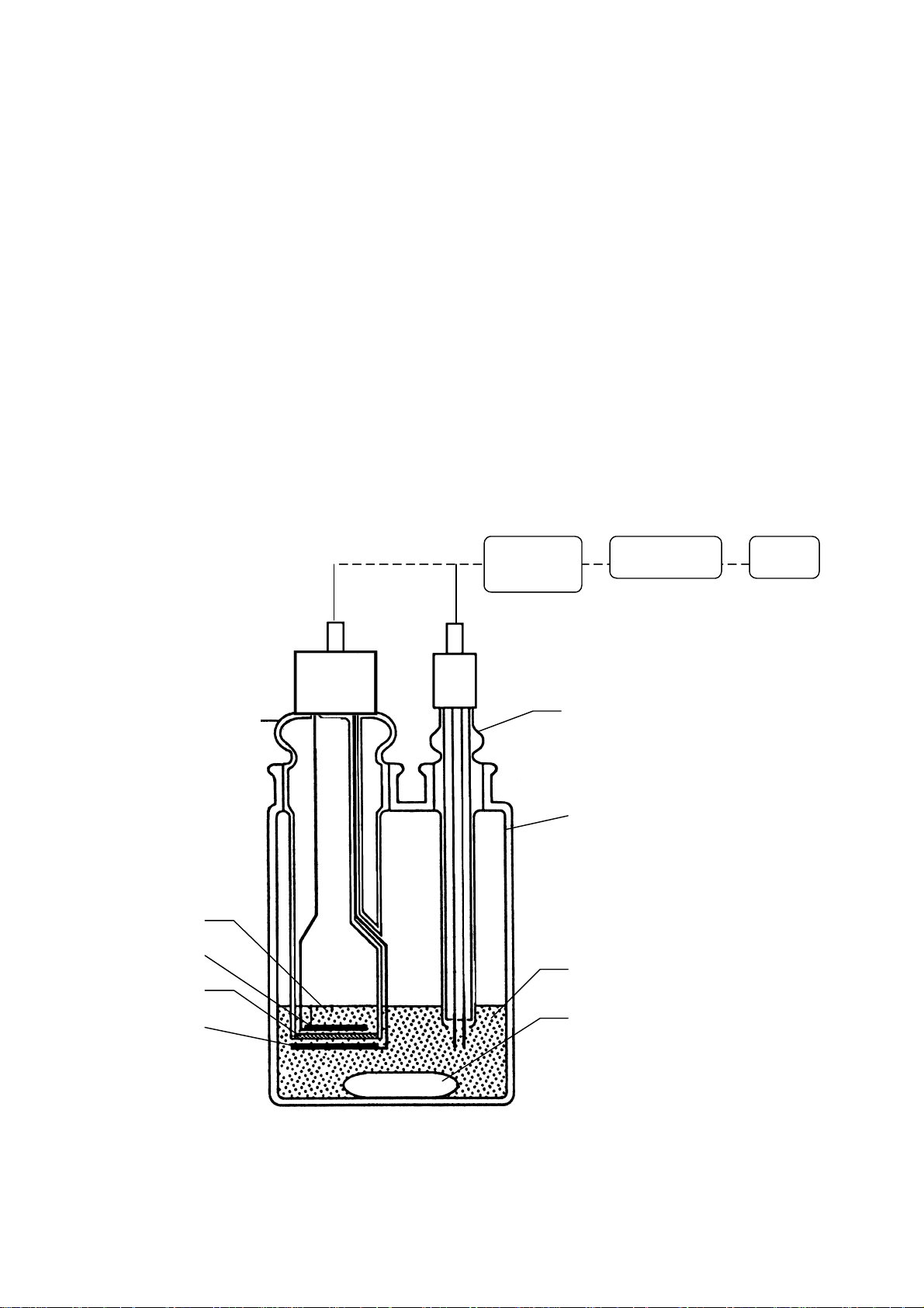
2
Catholyte
Cathode
Membrane
Detection/
Control unit
Microconputer Display
Detection electrode
(double platinum pin electrode)
Titration cell
Anolyte
Anode
Rotor
3

4. Setting up the system
4.1 Supplied parts
The carton box that has been delivered to you contains the MKC-500 and supplied parts including Operating
manual as per below list. Please identify the supplied parts with the list, and if you should find any part missing
or broken, contact your local dealer.
MKC-500 MKC-500
2-component cell 1-component cell
1. Main unit.................................................................................MKC-500 1 unit 1 unit
2. Power cord with earth wire (AC100/120V area) ....................#320-3198 1 pce 1 pce
(AC220/230/240 area)................#320-3461
(for UK)......................................#320-4199
3. AC 3-pin Adapter (AC100V only)..........................................#320-3199 1 pce 1 pce
4. Earth wire (AC100V only)......................................................#433-3331 1 pce 1 pce
5. Titration cell unit....................................................................#433-0005 1 set ⎯
6. Titration cell unit....................................................................#433-0071 ⎯ 1 set
7. Drain bottle.............................................................................#500-3134 1 pce ⎯
8. Funnel.....................................................................................#500-3159 1 pce ⎯
9. Stirrer spinner (35mm)...........................................................#500-3362 1 pce 1 pce
10. KF grease (5g)......................................................................#433-3138 1 pce 1 pce
11. Septum...................................................................................#523-3161S 10 pcs 10 pcs
12. Anode tool.............................................................................#075-3411 1 pce ⎯
13. Power fuse (T3.15A/250V for AC100/ 120V ).......................#338-5028 2 pcs 2 pcs
(T1.6A/250V for AC220/230/240V) ..................#338-3252 2 pcs 2 pcs
13. Operating manual..................................................................#595-0006 1 copy 1 copy
14. Warranty................................................................................ 1 copy 1 copy
15.Manual solvent exchanger......................................................MLC-500 ⎯ 1 unit
4

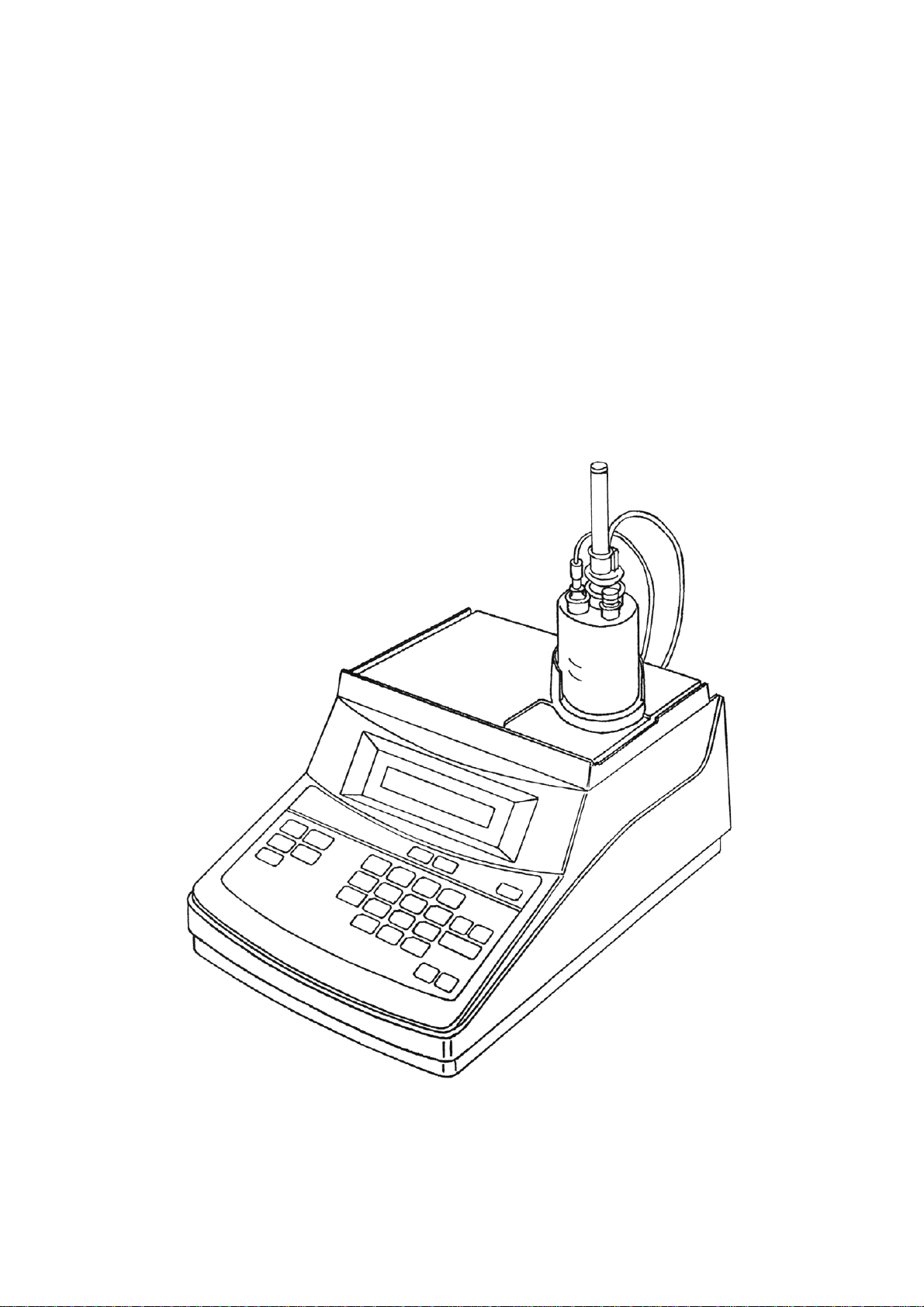
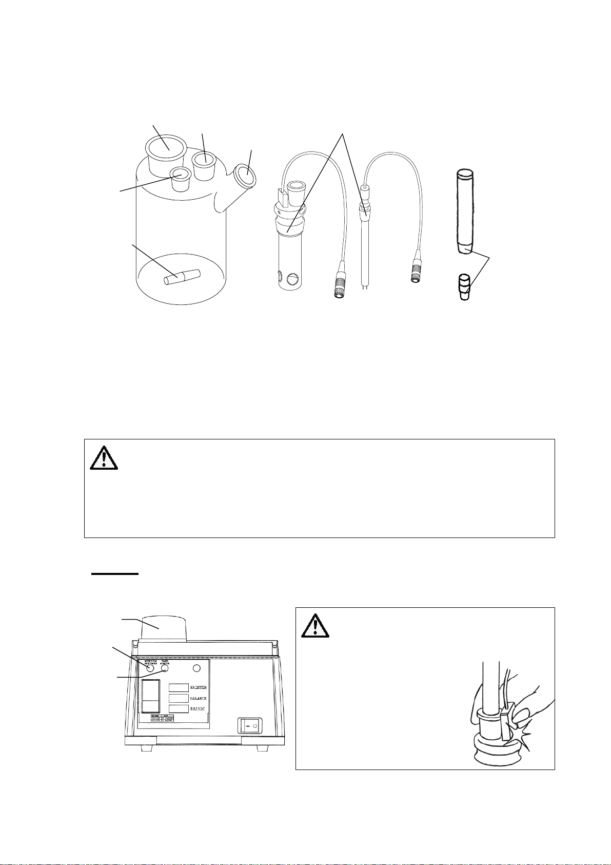
4.2 Parts name and functions
g
t
Detection electrode
measures potential
in the cell to detec
endpoint.
Fuse box
where power fuse is replaced
with new one.
Desiccator
keeps air dried.
Inner burette(anode and cathode
electrode combined into one unit)
generates iodine and titrates
moisture content.
Injection port(for syringe)
allows the sample injected into
the cell.
Titration cell
in which iodine and water react
for coulometric titration.
Cell holder
secures the titration cell.
Display screen
shows measurement results or
mode of the instrument.
Keypad
Enter desired parameters and
controls titration.
Input for inner burette
Plug in the connector from
inner burette.
Input for detection electrode
Plug in the cable end from the
electrode.
Port for Printer
Plug in the printer cable here.
Port for Balance
in the cable from Balance.
Plu
5
Voltage selector
Power switch
RS-232C connector
Interface for communication
with PC or other external
device.
Connector for power cable

Key to enter Titration parameter.
Press the key again when finishing parameter setting.
Key to enter parameters for Calculation or Report.
Press the key again when finishing parameter setting.
Key to enter Sample No., Lot No. or Sample weight.
Press the key again when finishing parameter setting.
Key to set up Function parameter.
Press the key when closing parameter setup.
0.Reagent Capacity
1.Recalculation
2.Factor
3.Memory clear
Key to enter Setup parameter.
Press the key when closing parameter setup.
0.Interface
1.Date & Time
2.Name
3.Serial No.
Key to activate Printer for printing.
Key to control Stirring speed.
Press the key again finishing rotating speed se tt i ng.
Key to perform Pre-titration.
Key to start Titration.
Key to turn the instrument into reset condition.
Key to select menu with ↑ mark or characters, and to show cell potential.
Key to select and reverse dot or character.
6

Key to select numerals.
~
Key to move the cursor.
Key to confirm the key entry.
Key to return the parameters on display to the previous screen.
Key to reverse a character or number by one space.
Key to clear the key entry that has been made.
7

4.3 Checking the operating voltage
Before switching on the instrument for the first time, make sure the voltage selector is set to the appropriate
line voltage. If it should be set to a wrong voltage, correct it by the following procedure:
(1) Open the cover of power inlet using a flat head screw driver.
(2) Pull out the voltage selector wheel, and put it back to the box so that the selected voltage can be seen when
the cover is closed.
(3) Close the cover and recheck the voltage display on the box.
Insert the driver and Pull out the voltage Close the cover.
open the cover. selector wheel.
Voltage selector
Make sure the power fuse conforms to the below rating chart.
For more details, see 12.10 Replacement of Power Fuse.
AC Line voltage Fuse Hz
100 V 90 - 120 V T3.15 A/250 V 50/60
120 V 103 - 132 V T3.15 A/250 V 50/60
220 V 198 - 242 V T 1.6 A/250 V 50/60
230 V 207 - 253 V T 1.6 A/250 V 50/60
240 V 216 - 264 V T 1.6 A/250 V 50/60
Voltage can be selected by the selector on the rear panel.
CAUTION
For continued protection against risk of fire,
replace only with same type and ratings of fuse.
Fuse
8
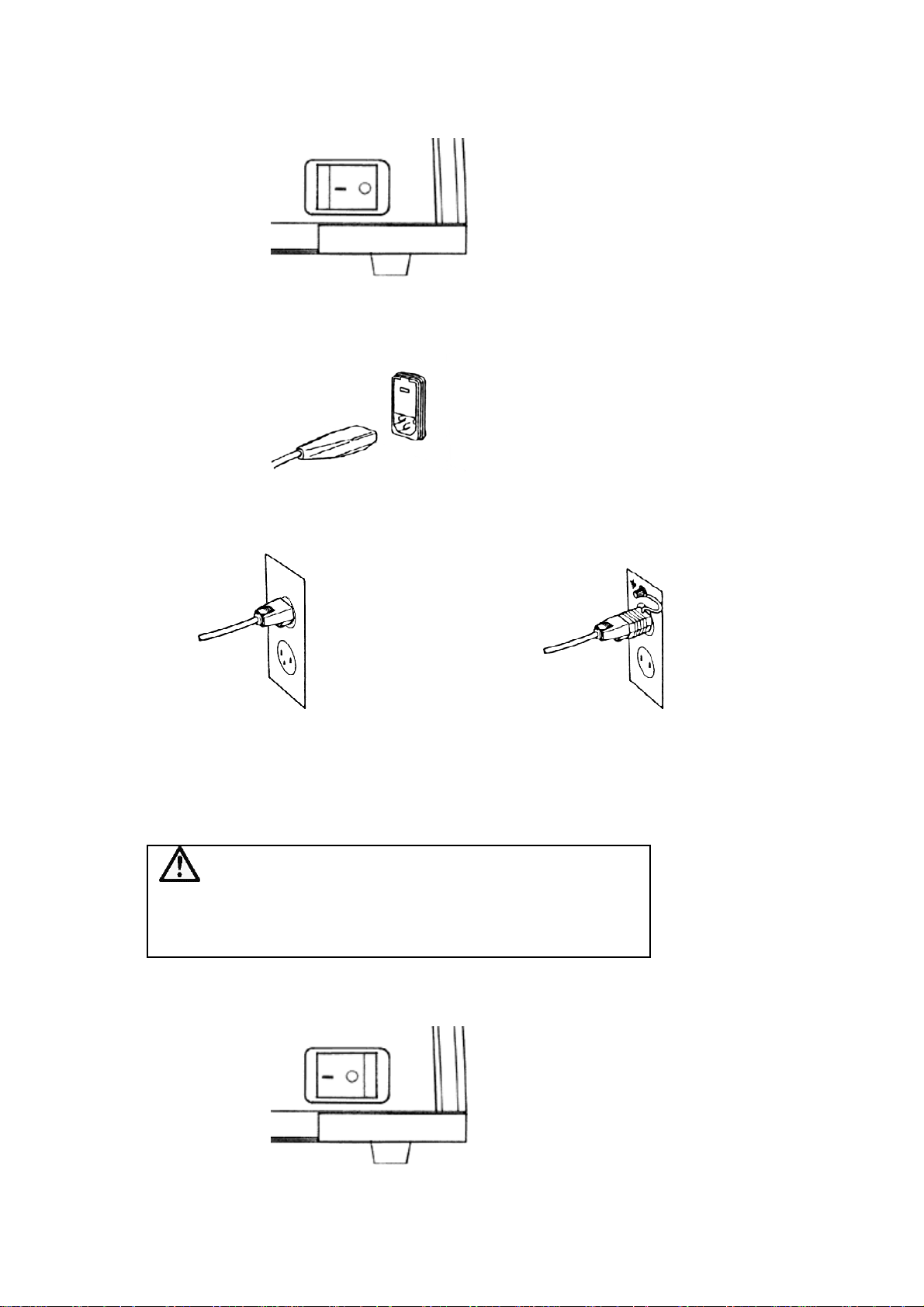
4.4 Turning on the power
(1) Make sure the power switch is in OFF position.
(2) Plug in the connector of supplied power cord to the unit.
(3) Plug in the other end of power cord to the power outlet.
<For 3-P consent> <For 2-P consent>
The 3-pin plug has an earth terminal First, plug in the AC-3P adapter to AC plug,
so that grounding by wire is not necessary. and then ground the green wire to the earth.
(4) Turn ON the power switch of the unit.
WARNING
Be sure to ground the earth line.
If not earthed, there will be danger of electric shock.
9

4.5 Initial display at start
When the power is turned on, the message (1) will appear on display for about two seconds. Then, the
message (2) on product version number will be shown for two seconds. Then, the message (3) will blink,
which keeps blinking until pre-titration starts.
(1)
(2)
(3)
C . M o i s t u r e T i t r .
V e r 1 .01
Pre-Tit r
4.6 How to confirm product version number
The product ver. number varies depending on what options and specifications you have selected for your
MKC-500.
Follow the below procedure to check its number:
With power turned on, make sure it shows Initial message or Main display.
Then, press [ 0 ], [ 0 ], [ 0 ] and press [ ↵ ] key.
The product number will appear for two seconds.
( 4.5 (2) )
Note!
This procedure must be worked on Initial display or main display.
10
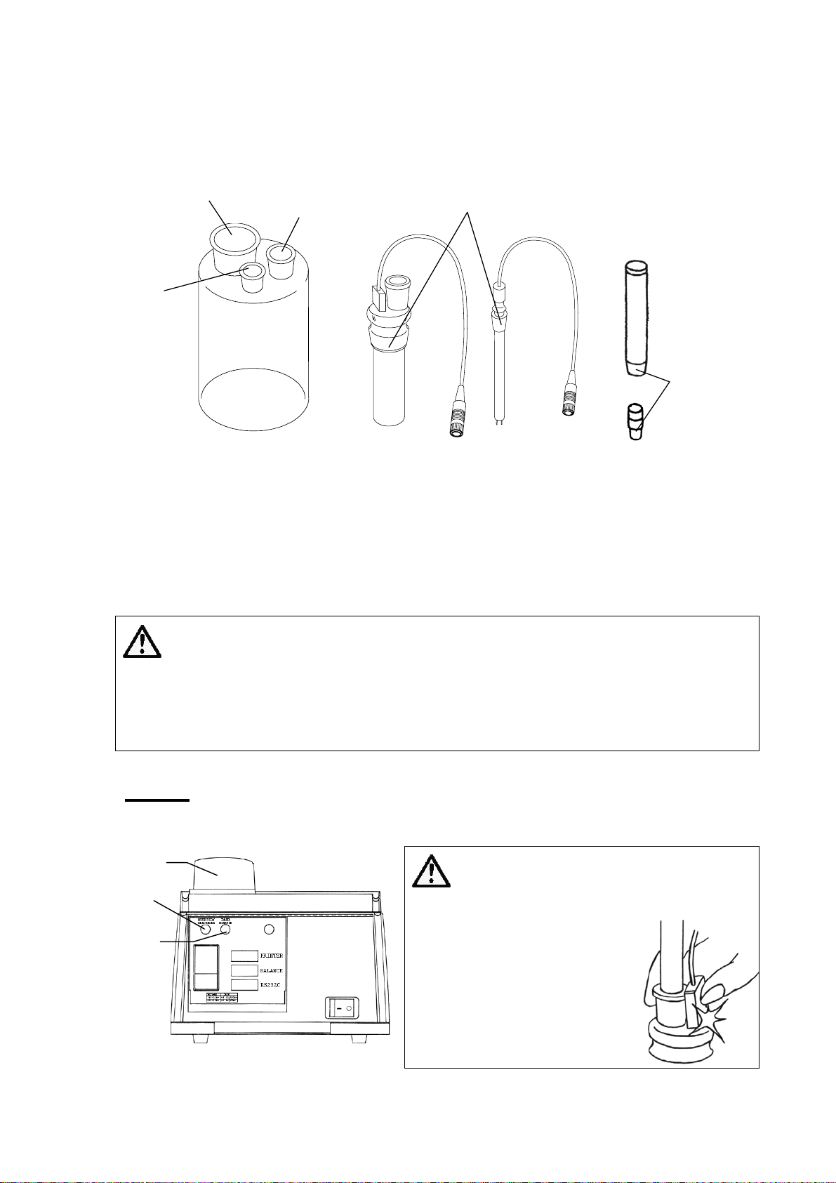
5. Installing the titration cell
5.1 Installation 2-comoponent cell
(1) Put the stirring spinner in the cell, and insert the inner burette and the detection electrode. Apply KF grease
around jointing parts.
Inner burette port
Detection
electrode port
Sample injection
port
Apply KF grease
Desiccator
Apply
KF grease
Titration cell
(2) Supply 100mL anolyte into Titration cell, and seal it after KF grease is applied around the injection p ort.
(The lower level line outside the titration cell shows 100mL line.)
(3) Supply 5mL catholyte into Inner burette, and seal it by the desiccant tube.
(4) Position the measuring cell in the cell holder.
Then, plug the cables of the electrode and the inner burette to the ports at the rear panel. (See next page)
Inner burette
(with diaphragm)
Detection electrode
Sample port
stopper
CAUTION
KF grease must be applied around all the jointed parts including the inner
burette, the detection electrode, sample port inlet and the low end of
desiccant tube. Check the jointed parts once a week. (See 12.1)
Neglegence of such maintenance will lead to solidification of those parts.
Note!
The protective seal on Desiccator must be peeled off.
Cell holder
Inner burette
holder
Detection
electrode
holder
CAUTION
To prevent the inner
burette from breaking by
handhold, do not snatch
the housing (black resin)
and desiccant tube by
fingers.
You may get hurt if it is
broken.
11
5.2 Installation 1-comoponent cell
(1) Put the stirring spinner in the cell, and insert the inner burette and the detection electrode. Apply KF grease
around jointing parts.
Inner burette port
Detection
electrode port
35mm spinner
Flask stopper port
Sample injection
port
Apply KF grease
Desiccator
Apply
KF grease
Titration cell
(2) Supply 150mL anolyte into Titration cell, and seal it after KF grease is applied around the injection p ort.
(The lower level line outside the titration cell shows 150mL line.)
(3) Position the measuring cell in the cell holder.
Then, plug the cables of the electrode and the inner burette to the ports at the rear panel. (See next page)
Inner burette
(Diaphragmless)
Detection electrode
Sample port
stopper
CAUTION
KF grease must be applied around all the jointed parts including the inner
burette, the detection electrode, sample port inlet and the low end of
desiccant tube. Check the jointed parts once a week. (See 12.1)
Neglegence of such maintenance will lead to solidification of those parts.
Note!
The protective seal on Desiccator must be peeled off.
Cell holder
Inner burette
holder
Detection
electrode
holder
CAUTION
To prevent the inner
burette from breaking by
handhold, do not snatch
the housing (black resin)
and desiccant tube by
fingers.
You may get hurt if it is
broken.
12

6. Method configuration
6.1 General
The MKC-500 has some parameters which are used for the titration, the calculation and the record of a titration.
These parameters can be modified to meet the requirements of individual titrations using the three function
keys, Titration, Result and Sample.
In a new MKC-500 parameters are initialized with default value (see 10.). With these parameters you can start
a titration without any change of parameter configuration.
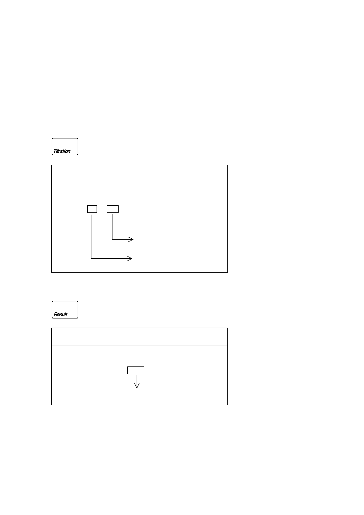
6.1.1 Basic structure
The parameters can be selected with the three function keys, Titration, Result and Sample.
Function key Description
Titration (parameters for controlling the titration)
Result (parameters for the result calculation)
(parameters for the result print out)
Sample (parameters for the sample)
13
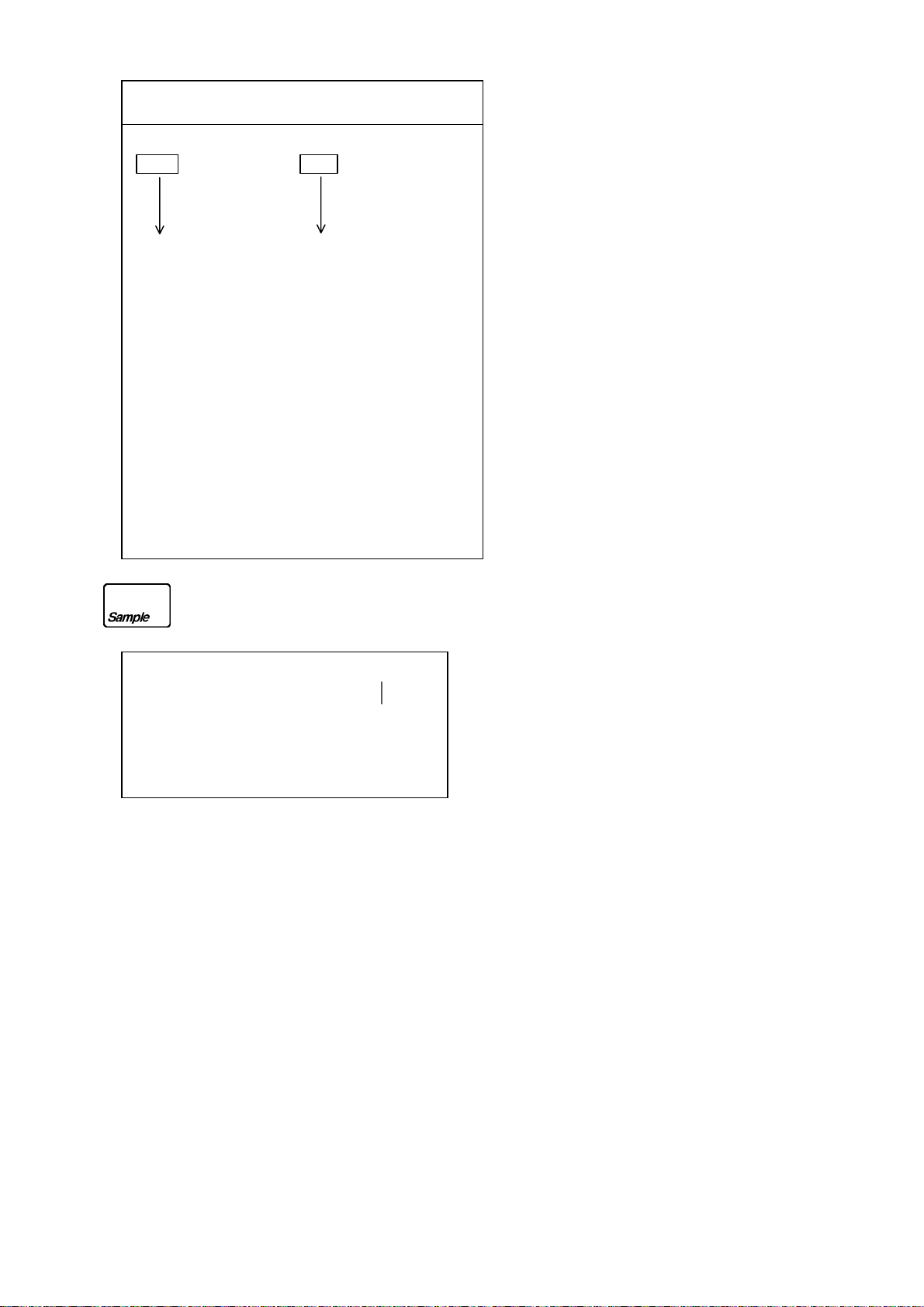
6.1.2 Structure of the parameter configuration
For entering and changing these display lines, see the chapters 6.2, 6.3, 6.4, 6.5.
Routine measurement by MKC-500 is simply started by [ Start ] key, and can be aborted by [Reset ] key.
Display messages and key entry are related like this:
Parameters of message ending with "↑" is selected on display by [-/Disp. ] key, and confirmed by [↵ ] key.
For parameters ending with "?", use numeric key and confirm by [↵ ] key.
The contents of each parameter are shown below:
t(stir) [s] ( 0 - 999 s )
t(wait) [s] (15 - 9999 s )
t(max) [s] ( 0 - 999 s )
Drift stop : rel ↑/ abs ↑/ off↑
Calculation↑
Unit : μg↑ /mg↑ /ppm↑ /%↑
Weight : fix↑ /var↑
Drift comp : auto↑ /off↑/ manu
Abs?(0.00 - 9.99)
Rel?(0.00 - 9.99)
↑
Drift?(0.0000 - 999.9)
14
Report ↑
Short
↑/ GLP ↑
Date & Time Date & Time
Sample No. Serial No.
Sample Weight Sample No.
Result Lot No.
Sample Weight
Factor
Result
Titr.Time
Drift
Blank
Name
Sample No. ? (00 - 00
99 - 99)
Lot ? (xxxxxxxxxx)
Wt1 ? (0.000000 - 999.9999)
Wt2 ? (0.000000 - 999.9999)
15

6.1.3 Initial parameters
Parameters Initial value
Titration
Result
Calculation
Report
Sample
t(stir) [s]?
t(wait) [s]?
t(max) [s]?
Drift stop
Unit
Weight
Drift comp
Drift comp:manu↑
Drift ?
Blank ?
Sample No. ?
Lot ?
Wt1 ?
Wt2 ?
0s
15s
0s
rel 0.1μg / s
Calculation↑
μg↑
f ix↑
auto↑
0.0μg / s
0μg
Short↑
00 - 00
5.0000g
0.0000g
16
6.2 Titration parameters
Here you can set the control parameters for the titration.
Entry Key Display Description
t(stir)[s]? 0 titration active, stirrer, no I
t(wait)[s]? 15
t(max)[s]? 0 time limit of titration, termination criteria. (0s
Drift stop : rel ↑ rel : stop s when drift is below.
Drift stop : abs ↑
Drift stop : off ↑
Drift stop : rel ↑
rel[μg/s]? 0.1
titration active, no termination during this
time. (more than 15s)
endless)
(entered value + drift value)
abs : stops when drift is below entered value.
off : no drift stop, termination after
{ t(stir) + t(wait) + t(max) }
- generation.
2
Note!
Do not select Drift Stop:off and t(max)=0 at the same time.
If selected, the alarm will beep when titration starts.
Note!
All parameters with the ↑ sign can be changed with the [ -/Disp. ] key.
All parameters with the ? sign require entry of a numeric value.
17

6.2.1 t(stir)[s], t(wait)[s], t(max)[s]
Start End
t(stir) t(wait) t(max)
No I2 generation I2 generation
a) t(stir) is the time that just stirrer is active.
b) t(wait) is the first possible time of titration termination.
Titration terminates here if drift stop level is reached.
c) t(max) is the time limit of titration.
titration time = t(stir) + t(wait) + t(max)
6.2.2 Drift stop : (rel / abs / off)
With the MKC-500 you have two possibilities to determine an endpoint.
a) Time Limit ( t(wait) + t(max) )
You define a fixed titration time. The titration stops after the defined time.
b) Drift stop
You define a drift stop. When the drift stop is reached, and the time "t(wait)"elapses, the titration stops.
You must define t(max) or Drift stop, or both.
If you define nothing, in other words t(max) 0 and Drift stop off, you get an error message: Para set miss!
Remarks regarding Drift stop
A high value of the Drift stop reduces the titration time, but the titration error increases, especially if the sample
releases its moisture slowly.
Repeated analysis of an oil sample sometimes causes a shift to a higher drift. In this case a low Drift stop setting
results in failure to detect the endpoint.
In the case of titrations with a sluggish approach towards the endpoint (due to side-reactions), a higher Drift stop
can help reduce the error.
18

Titration curves of a rapid and a slow moisture release with two Drift stop :
μgH2O/s
L1
L2
A
End2 End2
Start Start
End1 End1
A : Drift
L1 : High value for Drift stop
L2 : Low value for Drift stop
End1 : Endpoint with L1
End2 : Endpoint with L2
19
6.3 Calculation parameters
The four calculation parameters are part of the result parameters you can select in a method.
Entry Key Display Description
Calculation ↑
Unit :μg ↑ Set the calculation result unit
Unit : mg ↑
Unit : ppm ↑
Unit : % ↑
Weight : fix ↑ Select fixed or variable
Weight : var ↑
Drift comp : auto ↑ Set the drift compensation
Drift comp : off ↑
Drift comp : manu ↑
Drift? 0
Drift? 1.0
Blank? 0
Blank? 1.0
Calculation ↑
Drift is entered here [μg/s]
Blank is entered here [μg]
Note!
All parameters with the ↑ sign can be changed with the [ -/Disp. ] key.
All parameters with the ? sign require entry of a numeric value.
20

6.3.1 Calculation formula (by unit)
(
(
)
Formula No. Description Formula
1
2 Concent rat ion calculation for weighed
Formula No. is selected automatically by result unit.
Calculation Result unit Formula No.
μg or mg
ppm or %
Data : Result of th e titration (μg)
DL : Drift Level (μg/s)
T : Measurement time (s)
Blank : The value for subtraction of result (μg)
Wt1 : Weight of syringe with sample in it
Wt2 : Weight of empty syringe
Therefore, the sample weight = Wt1-Wt2
Moisture calculation
Result in μg or mg.
liquid or solid samples.
Result in ppm or %
1
2
When Drift comp:auto is selected, this value represents the drift at time [ Start ] key is pressed.
When Drift comp:manu is selected,this is manually input value.
When Drift stop:off ↑ is selected,t=(t(stir)+t(wait)+t(max)) (s)
When Drift stop:rel ↑ /abs ↑ is selected, t=<
Factor Data DL t Blank×−×−
Factor
t(stir)+t(wait)+t(max) (s)
Data DL t Blank
×
−×−
Wt1 Wt2
−
)
(ppm)
Note!
21
Even when ppm or % is selected for calculation results, if Wt1-Wt2=0, the
display will show the results in mg and printout in μg and mg.

6.3.2 Weight : (fix / var)
This parameter is necessary when calculation formula 2 is selected.
fix :
If you choose fix, you can enter fixed sample size by the sample key.
(MKC-500 doesn’t ask you to enter the sample size before or after the titration)
var :
If you choose var, you can enter the sample size by the sample key.
Input sample weight each time at measurement. If it is not input, the message on display will ask Operator for
Wt1 and Wt2 when titration is over.
6.3.3 Drift comp : (auto / off / manu)
auto : ( should be used normally )
The drift is automatically compensated by the measured value of the drift before sample injection.
off :
The drift is not compensated.
manu :
The drift is compensated by the value entered here.
6.3.4 Blank
The Blank is the amount of water that is added with a solvent or an extraction medium, or water that enters the
titration vessel while loading the sample.
This water doesn’t belong to the sample, the blank value has to be subtracted from the result.
6.3.5 Factor
The Factor is the value for multiplication of result. (see 9.4)
22

6.4 Parameters for Report
Net
The report parameters allow you to define the format of your report for a particular method.
With Short format , Date & Time, Sample No., Wt1, Wt2, Net and Result are automatically printed out.
With GLP format, Date & Time, Serial No., Sample No., Wt1, Wt2, Net, Factor, Result, Titration time, Drift,
Blank and Name are automatically printed out.
Entry Key Display Description
Calculation ↑
Report ↑ Set the report parameters
Short ↑
GLP ↑
Report ↑
Note!
You can change all parameters with the ↑ sign using the [ -/Disp. ] key.
Below shows comparison of print format between Short form and GLP:
<Short form>
Date : date and time of measurement
Sample No. : sample number
Wt1 : weight of syringe and sample weight
Wt2 : weight of syringe
Net : weight of sample
Result : amount of water (concentration or weight )
***Result***
Date 95/12/09 11:01
Sample No. 00-34
Wt1 42.5384g
Wt2 42.0213g
0.5171g
Result 1734.8μg
3354.9ppm
23

Net
N
<GLP form>
Date : date and time of measurement
Serial No. : production number of the instrument
Sample No. : sample number
Lot No. : lot number
Wt1 : weight of syringe and sample
Wt2 : weight of syringe
Net : sample weight
Factor : factor value
Result : amount of water(concent rat i o n or wei ght )
Titr. Time : measurement time
Drift : drift value
Blank : blank value
Name : name of operator
***Result***
Date 95/12/09 10:57
Serial No. LCA06202
Sample No. 00-33
Lot No. A960123
Wt1 42.5384 g
Wt2 42.0213 g
0.5171g
Factor 1.00
Result 1728.7μg
3343.0 ppm
Titr.Time 00:01:48
Drift 0.04 μg/s
Blank 0μg
ame KEM.TARO
24

6.5 Parameters for Sample
Desired parameters on the sample can be selected including sample number, lot number and sample size for
concentration calculation.
Entry Key Display Description
Sample No. ? 00 - 00 Enter sample number by numeric key.
Sample No. ? 01 - 00 Enter sample number of high order.
Sample No. ? 01 - 00
Sample No. ? 01 - 01 Enter sample number of low order.
Lot ? Enter lot number by [ -/Disp. ], [ ]and
Lot ? A32-01
Wt1 ? 5.0000
numeric keys.(up to ten characters)
Wt1 ? 4.1235
*Sample parameter can be input during titration.
*If Weight of calculation parameter is var ↑ and sample size is not entered, the display message will ask Operator
for Wt1 and Wt2 after titration is finished.
*Sample number of low order will be added up after each measurement.
Wt2 ? 0.0000
Wt2 ? 4.0173
Enter weight(g) of (syringe+sam pl e).
Enter weight(g) of syringe after sample is
injected.
25

Note!
If Wt1-Wt2 is set to zero(Wt1-Wt2=0) and ppm or % is selected for
calculation results, it will be shown in mg and printed in μg or mg.
Note!
All parameters with the ? sign require entry of a numeric value.
26

7. Example of actual operation
7.1 Status diagram of titration
Power ON
Pre-Titr blinks
Pre-Titr
Pretitration
Ready/Stable
Start
shows the mode of instrument
shows key input on MKC-500
Reset
Samm.In.↔Start
Reset
Start
Titration
27

7.2 Titration
With default parameters in a new MKC-500, you can start a titration without changing parameters.
Start of the first titration:
Set up the MKC-500 as described in chapter 4.3 and 5.
Turn on the power switch. "Pre-Titr" flashes on the display.
Start pretitration:.
Press the [ Pre-Titr ] key ; the pretitration will start.
Wait until the display shows "Stable".
The MKC-500 is now ready for titration.
Start titration:
Press the [ Start ] key.
The display : Samp. In.
Inject a sample using a syringe through the septum (for example 1 mL methanol).
Press the [ Start ] key again then the titration starts.
After the titration is finished, the result is displayed and printed out. (Printer is optional.)
The MKC-500 is now ready to start the next titration. The titration cell is kept free from water by continuous
titration. Press any key, then the display shows "Stable".
←→ Start
Entry Key Display Description
Pre-Titr (flashing) Standby
66 * Pre - Titr Pretitration
15 ⇒ Ready Wait until the display shows "Stable"
3 ⇒ Stable
3 ⇒ Samp.In. Inject the sample into the titration cell
3 ⇒ Start
43 * 45.8 μg
7 50.3 μg The result is displayed and printed
3 ⇒ Ready/Stable MKC-500 is ready for the next titration
28

Note!
The MKC-500 will shift to Reset condition after titration is finished, however,
it is recommended to press [ ↵ ] key after measurement results are recorded
so that the condition of the measuring cell can be checked to see if it is in
Ready or Stable.
Reset condition can be reached by other key than [ ↵ ], and other display
screen can be reached by pressing such keys as Parameter Setup or key for
separate display message screen.
Note!
If Drift Stop:off ↑ is selected and [ Reset ] key is pressed during titration, the
measurement results until [ Reset ] key is pressed will be printed out.
7.3 Pretitration
Turn on the power switch.
On the display "Pre-Titr" flashes (the MKC-500 is in the Standby mode).
Press the [ Pre-Titr. ] key in order to start pretitration.
If the stirrer is not active, press the [ Stirrer ] key and set stirrer speed (see also chapter 11.1)
After the pretitration the MKC-500 switches to the modes "Ready" and then, "Stable"
Status : Pre - Titr The solvent is titrated out.
Status : Ready The value of the drift is 10.0 μg H
Ready for rough measurement.
Status : Stable The change in the drift is 0.1 Δ μg H
Stable drift . Ready for accurate measurement.
The titration cell is kept water-free by continuous titration.
It is possible to start titration in "Ready" or "Stable" mode.
After the titration MKC-500 always returns to in mode "Ready" or "Stable" depending on the drift stability.
O / s or less.
2
O /min or less.
2
Entry Key Display Description
Drift not stable
3 ⇒ Stable High accuracy measurement ready
29
126 * Pre - Titr Pretitration in progress
21 ⇒ Ready Rough measurement ready
Drift stable

Note!
If you reconfigure the MKC-500 or replace the reagents, a high amount of
moisture will enter the titration cell. In this case it may take longer to achieve the
"Ready" and "Stable" status.
Display status Stable :
μg/s status Data
Drift level Status display
(μ gH
Stop Pretitration
In order to exit the status Pre-Titr, Ready or Stable, press the [ Reset ] key.
The status indicated on the display : "Pre-Titr" flashes.
During this time moisture (drift) is not titrated and the instrument is thus not ready to start titration.
To start pretitration, press the [ Pre-Titr ] key.
See also the chapter 7.1, Status diagram of titration.
. 0 3
O/s)
2
⇒
St abl e
30

7.4 Titration with Balance
With the MKC-500 you can enter the sample weight manually using the keypad or automatically when a
balance is connected.
You can activate the weight transfer by pressing the [ -/Disp. ] key
Connect MKC-500 and Balance.
Input sample number and lot number by Sample key, and leave it in waiting condition for Wt1.
Measure the weight of syringe filled with sample for measurement. Place the syringe on Balance and wait until
it becomes stable. Then, press [ -/Disp. ] key. The Wt1 will be read by MKC-500.
Press Start key and inject the sample, and then press Start to titrate. Place the syringe after the sample is injected.
When the display message asks for Wt2 after titration is over, press [ -/Disp. ] key to read Wt2.
Calculation results will be displayed at the end.
Entry Key Display Description
.01⇒Ready/Stable Waiting for titration start.
Sample No. ? 00 - 00 Enter sample number.
Sample No. ? 01 - 00 Enter sample number of high order.
Sample No. ? 01 - 00
Sample No. ? 01 - 01 Enter sample number of low order.
Lot ? Enter lot number by [ -/Disp. ], [ • ] or
numeric keys.
Lot ? A32-01
Wt1 ? 5.0000
31
Wt1 ? 4.3259 Read weight from Balance (syringe+sample)
Wt2 ? 0.0000
Start titration.

Entry Key Display Description
.01⇒Samp. In.
. 01⇒Start
33 * 1124.7μg
Wt2 ? 0.0000 Beep sounds to tell the end of titration with
Wt2 ? 4.0146 Weight of syringe has been read from
.03 4176.2ppm Measurement results are calculated and
.02⇒Ready/Stable Returns to Reset condition.
Now, inject sample into the cell.
Electrolysis begins and titration starts, and
the display will show the amount of water per
unit time and then titrated amount of water.
message asking for Wt2.
Balance.
displayed.
Note!
Even if the amount of Wt1-Wt2 becomes in minus, its absolute value will be
read.
32

8. Setup
8.1 General
The MKC-500 has 5 functions for additional possibilities, such as Interface, data & time, Name, Serial No.
Setup No.
0.Interface
1.Date & Time
2.Name
3.Serial No.
4.Cell Type
Setup [ 0-4 ] ?
↓
0. Interface
Interface : RS-232C / Printer / Balance
KEM/Mettler/A&D/Shimadzu/Sartorius
Printer: IDP-/DP-/Other
Baud rate: 300/600/1200/2400/4800/9600
Parity: even/odd/none
Data bits: 7/8
Stop bits: 1/2
(Caution: The parameters of IDP-and
DP-are fixed.)
Baud rate: 300/600/1200/2400/4800/9600
Parity: even/odd/none
Data bits: 7/8
Stop bits: 1/2
Soft HS: off/on
33

1. Date & Time
YY MM DD ? ( 6 numbers )
HH MM ? ( 4 numbers )
2. Name
Name ( 15 characters )
3. Serial No.
Serial No.
4. Cell Type
With Diap h r agm ↑
Diaphragmless ↑
Note!
Press the key when closing parameter setup. The display will return to the
screen for selection of Setup number. To return to the previous display from
Selection of Setup number, press [ Setup ] or [ Esc. ] key.
Note!
All parameters with the ↑ sign can be changed with the [ -/Disp. ] key.
All parameters with the ? sign require entry of a numeric value.
34

8.2 Interface (Setup 0)
The MKC-500 has three interface for the connection, RS-232C, Balance and Printer.
With this function you can set the configuration of the interface.
RS-232C
MKC-500 can communicate with external device via RS-232C cable. Here you will set up necessary protocol to
match digital configuration.
Entry Key Display Description
Setup [ 0-4 ] ?
Setup [ 0-4 ] ? 0
Interface
RS232C↑ Select the RS-232C.
Baud rate : 4800↑ Select the Baud rate.
Baud rate : 9600↑ Choose fr om 300, 600, 1200, 2400, 4800 and
Parity : none↑ Select the Parity.
Parity : even↑ Choose from even, odd and none.
Data bits : 8↑ Select the Data bits
Data bits : 7↑ Choose from 7 and 8
Stop bits : 1↑ Select the Stop bits
Stop bits : 2↑ Choose from 1 and 2
Soft HS : off↑ Select the Soft Hand Shake.
Soft HS : on↑ Choose from off and on
9600 Baud.
Setup [ 0-4 ] ?
Note!
For details of data communication via RS-232C, refer to MKC-500 Serial
Communication Manual.
35

Balance
When an electronic balance is connected to MKC-500, sample weight from Balance can be read automatically to the
MKC-500. Here is how to enter keys to match your Balance.
Entry Key Display Description
Setup [ 0-4 ] ?
Setup [ 0-4 ] ? 0
Interface
RS-232C↑
Balance↑
Bal : KEM↑
Bal : A & D↑
Setup [ 0-4 ] ?
Select the RS-232C.
Select the Balance.
Select the type of Balance.
Choose from KEM,Mettler, A & D,
Shimadzu and Sartorius
Printer
Optional printer can be connected as follows.
Entry Key Display Description
Setup [ 0-4 ] ?
Setup [ 0-4 ] ? 0
Interface
RS232C↑ Select the RS-232C.
Balance↑ Select the Balance.
Printer↑ Select the Printer.
Printer : IDP-↑ Select the type of printer.
36

Entry Key Display Description
Printer : DP-↑ Choose from IDP-,DP-, and Other
Printer : Other↑
Baud rate : 4800↑
Baud rate : 9600↑ Choose from 300, 600, 1200, 2400,4800 and
Parity : none↑ Select the Parity.
Parity : even↑ Choose from even, odd and none.
Data bits : 8↑ Select the Data bits
Data bits : 7↑ Choose from 7 and 8
Select the Baud rate.
9600 Baud.
Stop bits : 1↑ Select the Stop bits
Stop bits : 2↑ Choose from 1 and 2
Setup [ 0-4 ] ?
Note!
The parameters of IDP- and DP- are fixed.
37

MKC-500 interface pin assignment
RS-232C
(1) (2) (3) (4) (5)
(6) (7) (8) (9)
GND
DTR
TXD
RTS
RXD
DSR
Balance
(1) (2) (3) (4) (5)
(6) (7) (8) (9)
GND
DTR
TXD
RXD
Printer
(1) (2) (3) (4) (5)
(6) (7) (8) (9)
GND
TXD
BUSY
38

8.3 Date & Time (Setup 1)
With this function you can set Date and Time.
Once date and time is input on MKC-500, the measurement date and time will be automatically printed out on
Printer. The stored date and time will be kept in good time by clock function of MKC-500 unless backup battery
runs down or the date and time is changed otherwise.
Entry Display Description
Setup [ 0-4 ] ?
Setup [ 0-4 ] ? 1
Date & Time
YY MM DD? 950601 Enter year, month and day
YY MM DD? 960204
HH MM? 1000
HH MM? 1330
Enter hour and minute
Setup [ 0-4 ] ?
39

8.4 User Name (Setup 2)
With this function you can set User name.
Entry Display Description
Setup [ 0-4 ] ?
Setup [ 0-4 ] ? 2
Name
_ Enter User name
A
Use the [ -/Disp. ], [•] and numeric keys.
A_
AB
Setup [ 0-4 ] ?
Note!
Characters can be shifted automatically by keeping [ -/Disp ] and [ • ] keys
pressed.
40

8.5 Serial No. (Setup 3)
With this function you can check the serial No.
Entry Display Description
Setup [ 0-4 ] ?
Setup [ 0-4 ] ? 3
Individual serial number of the unit is input in plant before shipment.
Serial No.
LC60420 The serial number is displayed
Setup [ 0-4 ] ?
Note!
Serial number can only be checked and confirmed but not for changing the
number itself.
41

8.6 Cell Type (Setup 4)
Set the cell type for measurement (2-component or 1-component).
Press [Setup] key.
Entry Display Description
Setup [ 0-4 ] ?
Setup [ 0-4 ] ? 4
Cell Type
Select “Setup 4”.
With Diap h r agm
Diaphragmless
With Diap h r agm
Setup [ 0-4 ] ?
Select the cell type with [←] [→] key.
* With Diaphragm: 2-component cell (with diaphragm)
Selected when two reagents, Anolyte and Catholyte,
are used.
* Diaphragmless: 1-component cell (without diaphragm)
Selected when only Anolyte is used.
Note!
Characters can be shifted automatically by keeping [ -/Disp ] and [ • ] keys
pressed.
42

9. Function
9.1 General
The MKC-500 has 4 functions for additional possibilities, such as reagent capacity, recalculation, factor, memory
clear.
Function No.
0. Reagent capacity
1. Recalculation
2. Factor
3. Memory clear
Function [ 0-3 ] ?
↓
0. Reagent capacity
A . Capa. [mg] ? ( 4 numbers )
C . Capa. [mg] ? ( 4 numbers )
Alarm Set : off / o n
A . Alarm [mg] ? ( 4 numbers )
C . Alarm [mg] ? ( 4 numbers )
1. Recalculation
Unit:μg / mg / ppm / %
Wt1 ? ( 8 numbers )
Wt2 ? ( 8 numbers )
Drift ? ( 5 numbers )
Blank ? ( 5 numbers )
2. Factor
Factor ? (5 numbers )
3. Memory clear
Memory clr. off / on
43

Note!
Press the key when closing parameter setup. The display will return to the
screen for Selection of Setup number. To return to the previous display from
Selection of Setup number, press [ Setup ] or [ Esc. ] key.
Note!
All parameters with the ↑ sign can be changed with the [ -/Disp. ] key.
All parameters with the ? sign require entry of a numeric value.
9.2 For Reagent life control and Alarm setting (Function 0)
The Karl Fischer reagent for coulometric titration has reagent capacity for measurement of water content.
Generally, 1000mg H
capacity for moisture measurement.(For details, see Instruction of the reagent you have purchased.) Exhausted
overdue reagent will lead to longer titration time, too low in the results or too high in the drift.
The MKC-500 can show you update reagent capacity that has been calculated from coulomb used in
electrolysis during moisture titration, and will let you know by alarm when the reagent has reached its preset
limit of capacity.
Function 0 provides the following functions:
* Displays reagent capacity both anolyte and catholyte.
* Clear incremented capacity to zero when reagents are replaced.
* Enter limit value for capacity. (Beep alarm can be switched by off/on.).
O for 100mL anolyte and 300mg H2O for 5mL catholyte are the approximate limit of
2
44

Entry Key Display Description
Function [ 0-3 ] ?
Function [ 0-3 ] ? 0
Reagent capacity
A. Capa. [mg]? xxxx Accumulated electrolytic current (moisture-
A. Capa. [mg]? 0 Enter 0 on anolyte replacement to delete
C. Capa. [mg]? xxxx
C. Capa [mg]? 0 Enter 0 on catholyte replacement to delete
Alarm set : off↑ Select alarm/no-alarm status for
Alarm set : on↑
A.Alarm [mg]? 1000 Enter alarm limit (mg H
A.Alarm [mg]? 500
C.Alarm [mg]? 300 Enter alarm limit (mg H
C.Alarm [mg]? 200
converted) of anolyte is displayed (mg H
accumulated value (reagentcapacity)
Accumulated electrolytic current
(moisture-converted) of catholyte is
displayed (mg H
accumulated value (reagent capacity).
reagent capacity.
capacity.
capacity.
2
O)
O) of anolyte
2
O) of catholyte
2
O)
2
Function [ 0-3 ] ?
Note
How to cancel alarm and display when Alarm set: on ↑ is selected:
when preset moisture-converted reagent life is reached, alarm by beep and
blinking message will be activated. To cancel the alarm, press any key (eg; [ ↵ ]
key, [ Esc. ] key, Numeric key, etc.) just like for ordinary operation after
measurement is finished. It is recommended to replace the reagents
immediately after the alarm has been turned off.
45

9.3 Recalculation (Function 1 )
If expected measurement results have not been obtained due to wrong parameter settings or erroneously input
sample weight, the measurement can be recalculated with correct parameters.
The recalculated results are printed out with (#) mark.
Entry Display Description
Function [ 0-3 ] ?
Function [ 0-3 ] ? 1
Recalculation
Select Function 1 for recalculation
Unit : μg↑ Select result unit.
Unit : ppm↑
Wt1 ? 5.0000 To correct sample weight, use [ • ] or numeric
Wt1 ? 4.37
Wt2 ? 0.000
Wt2 ? 3.86
keys for Wt1, Wt2.
(μg, mg, ppm, %)
Drift ? 0.03 The first display is for drift value.
Blank ? 0 Then, enter Blank value.
1325.4ppm
Function [ 0-3 ] ?
Recalculated results are displayed and
printed.
46

Note!
Net
N
Even when ppm or % is selected, if Wt1-Wt2 is zero(Wt1-Wt2=0), the
recalculated results will be shown in mg, and printed in μg or mg.
Note!
For recalculation with new factor value, enter the corrected factor before
recalculation.
Shown below is an example of recalculated results in ordinary print format.
Printed in short form Printed in GLP form
[ Recalculation ]
Date 95/12/09 11:01
Sample No. 00-34 (#)
Wt1 42.5384 g
Wt2 42.0213 g
Net 0.5171 g
Result 1734.8 μg
3354.9 ppm
[ Recalculation ]
Date 95/12/09 10:57
Serial No. LCA06202
Sample No. 00-33 (#)
Lot No. A960123
Wt1 42.5384 g
Wt2 42.0213 g
0.5171 g
Factor 1.00
Result 1728.7 μg
3343.0 ppm
Titr. Time 00:01:48
Drift 0.04 μg/s
Blank 0 μg
ame KEM.TARO
47

9.4 Factor value setup (Function 2)
The MKC-500 is Karl Fischer Moisture Titrator and does not require Factor valu e unlike volumetric titration,
however, the factor can be set up in order to adjust measurement according to the effect of sample or the syringe
that is used for sampling.
This factor value will be added in the equation for calculation.
Entry Display Description
Function [ 0-3 ] ?
Function [ 0-3 ] ? 2
Factor
Factor ? 1.00 Enter factor value by [ • ] and numeric
Factor ? 0.998 Confirm the factor value.
Select Function 2 for factor entry.
keys.
Function [ 0-3 ] ?
48

9.5 Initialize to default (Function 3)
All the stored parameters can be cancelled and reversed to default values initially input in plant before shipment
by Function 3.
Entry Display Description
Function [ 0-3 ] ?
Function [ 0-3 ] ? 3
Memory clr.
Memory clr. : off↑
Memory clr. : on↑ Select to clear memory.
Function [ 0-3 ] When beep sounds, turn off the
SRAM Init. Press any key (eg; [↵] key). It beeps.
Select Function 3 to clear saved data.
switch, and then, turn it on after five
(5) seconds.
Note!
C. Moisture. Titr. This message turns on for two (2)
Pre-Titr
seconds.
All the data has been cleared, and it
returns to initial display.
Setup function will not be affected by initializing the parameter.
49

10. Initializing parameters and default values
The procedure of initialization of parameters to default is described in 9.5. All the data of parameters are reversed to
default values, which are preset in plant before shipment.
Parameter Default value
Titration t(stir) [ s ] ? 0s
t(wait) [ s ] ? 15s
t(max) [ s ] ? 0s
Drift stop rel 0.1μg/s
Result Calculation↑
Calculation Unit μg↑
Weight fix↑
Drift comp auto↑
Drift comp : manu↑
Drift ? 0.0μg/s
Blank ? 0μg
Report Short↑
Sample Sample No. ? 00-00
Lot ?
Wt1 ? 5.0000g
Wt2 ? 0.0000g
Function
Reagent capacity A.Capa. [mg] 0mg
C.Capa. [mg] 0mg
Alarm set off↑
Alarm set : on↑
A.Alarm [mg] ? 1000mg
C.Alarm [mg] ? 300mg
Recalculation Unit μg↑
Wt1 ? 5.0000g
Wt2 ? 0.0000g
Drift ? 0.0μg/s
Blank ? 0μg
Factor 1.00
Memory clr. off↑
Stirrer Speed [ 0-9 ] 4
Note!
The Setup function is not affected by the initialization.
50

11. Special Keys
The MKC-500 has several special keys.
These Keys are :
the Stirrer Key stirrer speed control
the Esc. Key reverse parameters to previous settings
the BS. Key reverse key entry by one space
the Clr. Key erase all key entries
the -/Disp Key switch function
the Print Key printer operation
the Reset Key interruption of a titration
11.1 The Stirrer Key
With the [ Stirrer ] key you can control the magnet stirrer in the titration cell.
You can set the speed of the magnetic stirrer. You can choose stirring speed from 0 to 9 (0 stops the stirrer).
For a titration under normal conditions use stirrer speed 4-6.
Entry Key Display Description
Speed [0-9] ? 3 The stirrer runs with speed 3
Speed [0-9] ? 4 The stirrer runs with speed 4
Speed [0-9] ? 5 The stirrer runs with speed 5
11.2 The Esc. Key
With the [ Esc. ] key you can quit the parameter entry.
If you want to change only the first parameter of a list, you can quit the parameter list with the [ Esc. ] key after
you have changed the parameter.
You can not interrupt a printout with the [ Esc. ] key.
11.3.The BS. Key
By this key, you can erase the key entry by reversing one space.
51

11.4 The Clr. Key
With the [ Clr. ] key you can clear the numbers and characters that have been entered.
11.5 The -/Disp. Key
1. Switch function in the parameter setting
Many parameters do not require entry of a value but have to be chosen from a given list, for example :
Drift stop : rel↑/ abs↑ / off↑
Weight : fix↑ / var↑
Printer : IDP- ↑/ DP- ↑/ Other↑
With the [ -/Disp. ] key you can change these parameters.
General : All parameters with the ↑ sign can be changed with the [ -/Disp. ] key.
2. Switch to automatic weight transfer from a connected balance
The sample weight can be entered manually or by pressing the [ -/Disp. ] key. The weight will then be
transferred from the connected balance.
3. Toggle between μg and mV
While a titration is running the information on the display can be toggled with the [ -/Disp ] key.
It toggles between μg and mV.
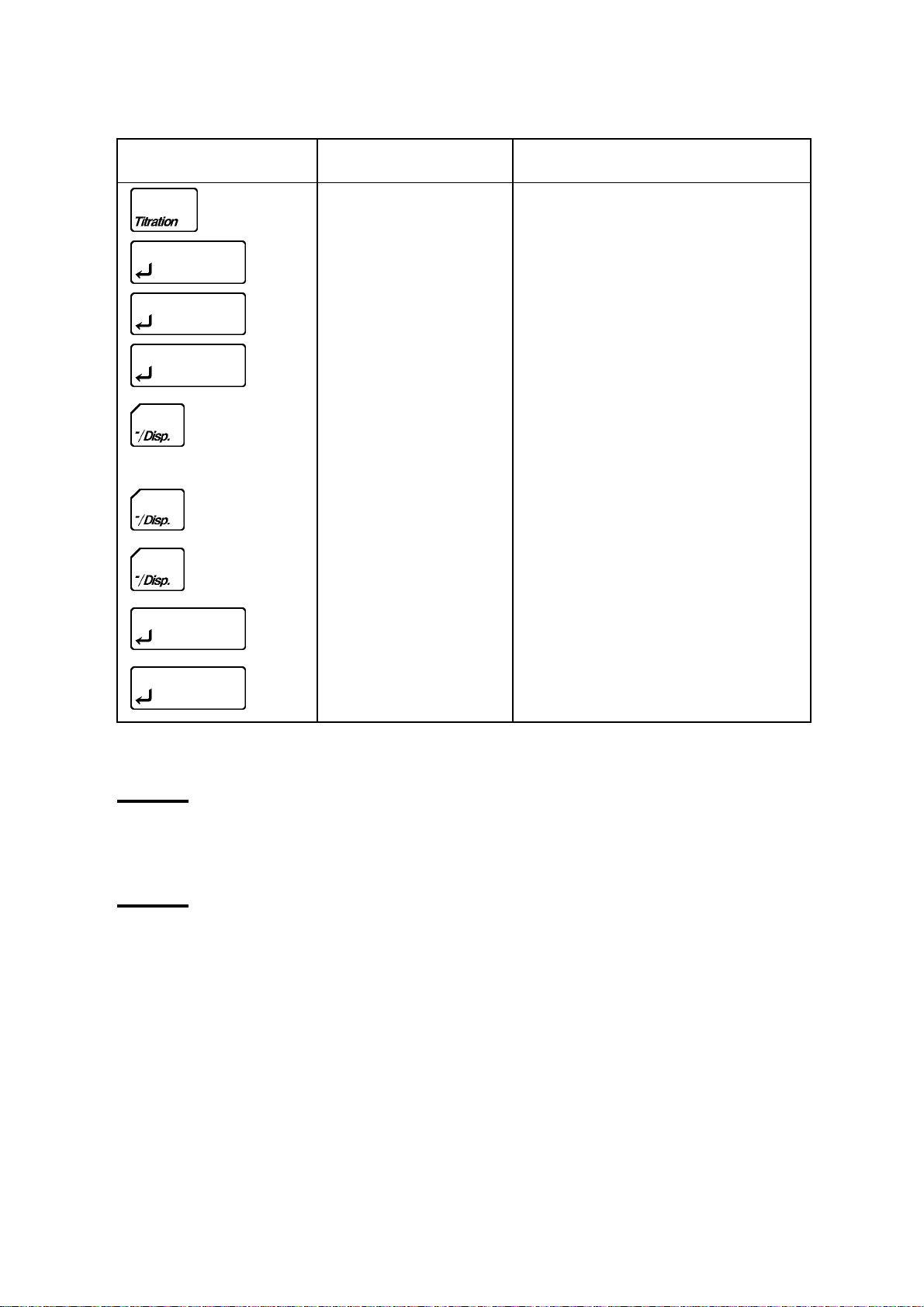
11.6 The Print Key
With the [ Print ] key you can print out parameters.
Entry Key Description
Printout of the titration parameters.
Printout of the calculation and
Press key, display
"Calculation↑" then
Press key, display
"Report↑" then
and then
and then
reportparameters.
Printout of the calculation parameters
Printout of the report parameters
Printout of the Setup parameters
Printout of the Function parameters
(within 1 s)
Printout of all of parameters
(titration, result, fanction and setup
parameters)
52

11.7 The Reset Key
With the [ Reset ] key you can interrupt a titration.
If you press the [ Reset ] key the titration will immediately be interrupted and the MKC-500 will return to the
"ready" or "stable" mode. No results will be calculated or printed.
Note!
If you have defined Drift Stop "off" (you have defined a titration time limit),
a result will be calculated with the titrated water until the interruption and
the entered weight ; the results are displayed and printed out. There is thus
a possibility to terminate a titration before the defined time limit is reached.
53

12. Maintenance
Please follow the below instructions in order to maintain the MKC-500 in good working condition.
12.1 Application of grease
Apply KF grease over the glass contact areas. Turn the parts approximately once a week to ensure they rotate
smoothly ; if not, apply a thin coating of grease.
Parts may otherwise stick and be difficult to separate. Do not apply too much grease as it may penetrate the
titration cell and increase the background owing to the water content of the grease.
Check the glass joints from time to time so that applied grease will not
solidifies. If it should stick to the glass, follow the instruction in 14.8.
12.2 Septum replacement
Change the syringe inlet port septum occasionally. An old septum is easily broken and allows air to enter the
titration cell thereby increasing the background.
12.3 Silica gel replacement
CAUTION
Replace the desiccator silica gel from time to time. When the silca gel in the titration vessel turns reddish, its
hygroscopic properties are impaired and it must be replaced immediately.
Also apply KF grease over the contact areas of the titration cell desiccator.
12.4 Anolyte replacement
Replace about 100mL of anolyte in the following cases :
• when the reagent capacity ( mg H
• if the liquid ( with added sample ) in the titration cell has exceeded the level mark "150",the diluted anolyte
will cause poor sensitivity and extended measurement time,
• when the drift level becomes too high.
O ) has reached 1000 mg H2O as indicated using Setup 1 "A.Capa",
2
Note!
Add 20 mL of ethylene glycol when measuring vaporized moisture or
gaseous samples.
Note!
After the replacement, enter "0" in Function 0 "A.Capa" to delete the
accumulated electrolytic current ( moisture-converted ) of anolyte ( reagent
capacity). ( See page 9.2)
54

12.5 Catholyte replacement (Not necessary for 1-component cell)
Replace about 5mL of catholyte in the following cases:
⋅ when the reagent capacity ( mg H
⋅ when about 5mL of background level is excessive,
⋅ one week after replacement of a reagent.
Periodic catholyte replacement is important. Otherwise the drift level will increase and the membrane could
become contaminated with foreign matter causing measurement errors.
O ) has reached 300 mg H2O as indicated by Setup 1 command,
2
Note!
Adjust the catholyte level to the lower mark on the titration cell.
Note!
After replacement, select Function 0, enter "0" up to "C.Capa",
accumulated electrolytic current ( moisture-converted ) of catholyte is set
to zero. ( See 9.2)
Caution
Karl Fischer Reagents are potentially hazardous. Do not inhale or allow skin
contact.
Replacement should be performed in a fume hood. Reagent should never be
poured down the drain.
12.6 Long-term storage measures
Plug out the power cord, and store the instrument in a room dry and cool without direct sunlight nor
vibration.It is recommended to pack in the unit in the box in wh ich the MKC-500 was delivered when you
purchased.
It is advisable to clean and dry the titration cell unit and keep it disassembled in a desiccator.
For cleaning and drying details, see chapter 12.7~12.9.
55

12.7 Cleaning detection electrode
f
When sample impurities have adhered to the platinum pins of the electrode, first wash with concentrated nitric
acid, then with methanol.
12.8 Cleaning inner burette
12.8.1 Cleaning steps
(1) Clean using alcohol
⋅ Press the [ Reset ] key.
The "Pre-Titr" display flashes.
⋅ Remove the inner burette from the titration cell and drain the catholyte.
⋅ Remove grease from contact areas with methanol.
⋅ Inject methanol into the cathode of the inner burette two or three times, then inject about 10 mL of
methanol. Place the inner burette in a beaker.
⋅ Add methanol to the beaker until it reaches the methanol level in the cathode. Let stand for about 30
minutes.
⋅ Follow the Drying Instructions below.
(2) Clean using chromic acid ( when foreign matter has built up on the membrane and the platinum surface ).
⋅ Use chromic acid instead of methanol in the steps above. Let stand overnight.
⋅ Drain the liquid out of the cathode. Repeat 5 or 6 times : Wash the cathode with pure water until the
yellowish color disappears. ( Rinse the chromic acid off the membrane.)
⋅ Follow the Drying Instructions below.
Note!
Chromic acid cleaning dissolution. Prepare by dissolving about 1.5 g of
potassium dichromate in 100 mL of sulfuric acid.
Chromic acid mixture is a highly reactive oxidizer. It is recommended to
wear protective gloves and glasses while you handle the acid. If it should
contact your skin, wash it away with abundant running water.
Chrome is a toxic heavy metal. Do not discard waste chrome or its solvent
into the sewer.
Dilute chromic acid mixture to 1% for reduction, and after no more existence
of Cr
For more details, please refer to documentations on how to dispose o
heavy metals.
CAUTION About chromic acid mixture
+6
is confirmed, adjust it to pH7.5 to 8.5, and filter it for storage.
56

12.8.2 Drying steps
(1) Warm air drying with a hair dryer.
• Blow warm air on the membrane until dry ( about 10 minutes).
(2) Drying with a vacuum dryer
• Place in a vacuum chamber for 2 hours or longer. This is more effective than using a hair dryer. A vacuum
dryer is very effective.
Low Pressure Dryer Vacuum Constant-temperature Dryer
12.8.3 Adjusting the length between anode and membrane
When the length between anode and membrane in inner buret is too close, it is impossible to electrolyte
correctly. In this case, insert the anode adjuster between anode and membrane on a level.
12.9 Cleaning and drying the measuring cell
* Remove Detection electrode, Inner buret and Sampling port stopper, and then drain out the reagent.
* Wipe off the grease around jointed parts with methanol.
* Rinse by neutral detergent under run ni n g water.
* After drying the glass ware in a heater dryer, either cool them in desiccator or dry them according to 12.8.2.
Note!
If the measuring cell is not dried well, the drift will show higher value.
Do not clean the inner cell in an ultrasonic cleaner because the inner cell is
precision made and it may break.
CAUTION About cleaning inner cell
57

12.10 Replacement of power fuse
(1) Turn off the power and plug out the cord.
(2) Open the box cover above power inlet by a flat screw driver.
(3) Pull out the two fuse holder using the screw driver.
(4) Replace the broken fuse by inserting new fuse to the same arrow direction of cover and holder, and close
the cover.
Open cover by driver Pull out fuse Same arrow direction Close cover
Danger of electric shock.
Before you replace the fuse, turn off power and plug out the cord.
WARNING
12.11 Backup battery
If the built-in backup battery energy runs down, the built-in clock will not keep correct time. When the b attery
needs to be replaced, please contact your local dealer or distributor.
58

13. Karl Fischer reagent
t
p
For Karl Fischer titration, appropriate reagent must be selected to the sample that you are going to analyze. Belo w
chart shows the type of sample and its corresponding reagents available on the market.
• For 2-component cell
Riedel-de Haën
Corresponding
Coulomat Aquamicron
General titration
Alcohols
Hydrocarbons
Ethers
Esters
Ketones Coulomat AK
Gases Coulomat AG
Fats and Oils Coulomat AG-H
Amines Coulomat AG
Karl Fischer
Sam
le
reagen
Coulomat AG
Coulomat CG
Coulomat CG-K
Coulomat AK
Coulomat CK
Coulomat CG
Coulomat CG
Coulomat CG
To use Coulomat AG,
add acetic acid, salicylate
or benzoic acid to 20% of
100mL of Coulomat AG.
MITSUBISHI
Aquamicron AX
Aquamicron CXU
Aquamicron AX
Aquamicron CX
Aquamicron AKS
Aquamicron CXU
Aquamicron AKS
Aquamicron CKS
Aquamicron AX
Aquamicron CXU
Aquamicron AX
Aquamicron CX
Aquamicron AX
Aquamicron CXU
Aquamicron AX
Aquamicron CX
Aquamicron AX
Aquamicron CXU
To use Aquamicron
AX, add 10g salicylate
acid to 100mL
Aquamicron AX.
Remarks
Coulomat AG/CG,
Aquamicron AX/CXU
are non-organic chlorines.
Formaldehyde can only be
titrated among other
aldehydes.
Coulomat CG-K
Aquamicron CXU are
non-organic chlorines.
Coulomat AG-H/CG,
Aquamicron AX/CXU are
non-organic chlorines.
To add, neutralize a basic
amine with an acid.
59

• For 1-component cell
t
p
Riedel-de Haën
Corresponding
Coulomat
General titration
Alcohols
Hydrocarbons
Ethers
Esters
Ketones Coulomat AK Formaldehyde can only be titrated
Gases Coulomat AG
Fats and Oils Coulomat AG-H
Amines Coulomat AG
Karl Fischer
Sam
le
reagen
Coulomat AG
To use Coulomat AG, add acetic
acid, salicylate or benzoic acid to
20% of 100mL of Coulomat AG.
Remarks
among other aldehydes.
To add, neutralize a basic amine with an
acid.
60

14. Troubleshooting
14.1 Error messages and malfunction rectification
Error message Cause Rectification
A.Capacity Over!
C.Capacity Over!
Current Error!
Elect Open!
Elect Short!
Meas. Over!
Over Titr.!
Para set miss!
Pre Amp Err-XX Inside Pre Amp of instrument is not
Accumulated electrolytic current
(moisture-converted)of anolyte has
exceeded anolyte capacity limit.
Accumulated electrolytic current
(moisture-converted)of catholyte has
exceeded catholyte capacity limit.
No electrolytic current flows.
No current to Detection electrode. • Check electrode for breakage or poor
Detection electrode is shorted or cell
potential is very low.
Moisture content measured has exceeded
100 mg H
Over-titration.
Excessive iodine is generated by anolyte
with time.
time(max):0s and Drift stop off ↑ have
both been set.
working correctly.
2
O.
• Replace anolyte.
• Reset A.capacity value.
• Replace catholyte.
• Reset C.capacity value.
• Sample liquid resistance is too great.
• Check anode and cathode for breakage
or poor contact.
• Make sure connectors are plugged in.
contact.
• Make sure connectors are plugged in.
• Check electrode connector for short-
circuit.
• Check cell potential and add water to
raise above 200mV.
Replace catholyte (anolyte if necessary),
make background level stable and
remeasure a smaller quantity sample.
• Clean anode if stained with foreign
matter.
• Move unit to another place if exposed
to direct sunlight.
• In case of pre-titration, add a little water
to cell.
• Set Drift stop rel ↑or abs ↑.
• Set t(max).
Please contact your local dealer or
distributor.
Note!
Press [ Reset ] key to exit from error message.
If the error message remains after all, contact your local dealer or distributor.
61

14.2 Power switch failure
START
Power outlet OK ?
YES
Fuse OK ?
YES
Voltage select OK ?
YES
Repair by
Manufacturer
NO
Collect power outlet
NO
Replace voltage selector fuse
NO
Set voltage selector properly
NO
AC Line voltage Fuse Hz
100 V 90 - 121V T3.15 A/250V 50/60
120 V 103 - 132V T3.15 A/250V 50/60
220 V 198 - 242 V T1.6 A/250V 50/60
230 V 207 - 253 V T1.6 A/250V 50/60
240 V 216 - 264 V T1.6 A/250V 50/60
We accept no responsibility whatsoever for any fault in or damage to the electrical circuit caused by wrong setting of
the voltage selector.
For continued protection against risk of fire.
Replace only with same type and ratings of fuse.
Everything OK ?
YES
END
CAUTION
62

14.3 Stirrer malfunction
START
Setting stirrer speed
with Stirrer key possible?
YES
Stir speed correct?
YES
Stirrer motor working?
YES
Rotor size OK?
YES
Foreign substance
in the titration cell?
NO
Rotor hopping?
NO
NO
Stirrer control impossible.
Repair by manufacturer.
NO
Set speed to 4-6 with Stirrer
key.
NO
Stirrer control impossible.
Repair by manufacturer.
NO
Use the same size rotor as
Standard Equipment.
YES
Take out the foreign substance.
Clean the cell if necessary.
YES
Change the same size of
Another one.
Repair by manufacturer
Everything OK?
NO
YES
END
Note!
If rotor is heated at high temperature, its magnetic force runs down.
63

14.4 Drift level excessive
START
Any leak?
NO
Too much grease applied?
NO
Anolyte capacity expired?
NO
Cayholyte capacity expired?
NO
Specific sample?
NO
Membrane wet with water?
NO
Membrane cracked?
YES
Replace septum.
Apply grease.
YES
Remove grease from titration
vessel.
YES
Replace anolyte.
YES
Replace catholyte.
YES
Check reagent in use.
YES
Clean and vacuum dry inner
burette.
YES
NO
YES
Anode in contract
with membrane?
NO
Detection electrode
looking bad?
NO
Detection electrode dirty?
NO
Contact manufacturer.
Everything OK?
YES
END
Replace inner burette.
YES
Insert anode adjustment jig between
membrane and anode(net) and ensure
cleacrance of 1.5-2mm.
YES
Replace detection electrode.
YES
Clean detection electrode.
64

14.5 Excess reagent consumption
START
Exposed to direct sunlight?
NO
Detection electrode
looking bad?
NO
Detection electrode dirty?
NO
Anolyte capacity expired?
NO
Catholyte capacity expired?
NO
Viscous substance
deposit on anode surface?
NO
Anode in contact
with membrane?
NO
Contact manufacturer.
YES
Move to another place to avoid
direct sunlight.
YES
Replace detection electrode.
YES
Clean detection electrode.
YES
Replace anolyte.
YES
Replace catholyte.
YES
Clean and vacuum-dry inner
burette.
YES
Insert anode adjustment jig between
membrane and anode (net) and ensure
clearance of 1.5-2mm.
NO
Everything OK?
YES
END
65

14.6 Endpoint not reached or reached too late
START
Drift stop off?
NO
Drift stop lower
μ
than 0.1
Any interface in reaction?
Anolyte capacity expired?
Catholyte capacity expired?
Water content
in sample too much?
g/s?
NO
NO
NO
NO
NO
YES
Titration continues until limit time.
YES
Increase drift stop value.
(generally rel 0.1
YES
Change reagent or try to use
indirect process.
YES
Replace anolyte.
YES
Replace catholyte.
YES
Reduce sample volume.
(See 14.7 Note)
μ
g/s)
YES
Sample deposit on
detection electrode?
NO
Contact manufacturer.
NO
Everything OK?
YES
END
Note!
Use ketones-specific reagent for ketonic sample.
Clean detection electrode and check the
sample dissolve in the reagent if it does
not disolve, change reagent or use
indirect method.
66

14.7 Poor reproducibility of measurement results
START
Sampling method improper?
NO
Sampling
volume and titration volume in
bad relation?
NO
Drift level low enough?
YES
No excessive reagent?
YES
Too long until endpoint?
NO
Drift stop optimum?
YES
Anolyte capacity expired?
YES
YES
NO
NO
YES
NO
YES
Find better sampling method.
See Note (next page).
Chack troubleshooting Chart 4.
Chack troubleshooting Chart 5.
Chack troubleshooting Chart 6.
Set Drift stop less than 0.1
(generally rel 0.1
μ
μ
g/s)
g/s.
NO
NO
Catholyte capacity expired?
NO
Anode in contact
with membrane?
NO
Any interferring substance?
NO
Contact manufacturer.
Everything is OK?
YES
END
Replace anolyte.
YES
Replace catholyte.
YES
Insert anode adjustment jig between
membrane and anode (net) and
ensure clearance of 1.5-2mm.
YES
Change reagent or try to use
indirect process instead of direct
one.
67

Note!
For reproducibility of measurement results, moisture content and sample
size relations in below chart is important.
Moisture content Sampling volume
50 - 100 %
10 - 50 %
1 - 10 %
0.1 - 1 %
0.01 - 0.1 %
0.001 - 0.01 %
0.0001 - 0.001 %
14.8 Glass contact areas jammed
If grease on the glass contact areas becomes hard and the respective parts are difficult to separate, take the
following steps;
(1) Discharge anolyte and catholyte.
(2) Heat the glass contact areas with a hair dryer to melt the grease.
WARNING
Do not try and open solidified jointed parts by force.
Glassware may break into piercing pieces for injury.
10 mg
10 - 20 mg
10 - 50 mg
10 - 100 mg
100 mg - 1.0 g
1 g - 10 g
10 g - 20 g
68

15. Display messages list
Display Printout Meaning
A.Alarm[mg]? Reagent capacity
Enter anolyte capacity alarm limit(mg H2O).
A.Alarm 1000mg
abs[μg/s]? Drift stop:abs
0.1μg/s
A.Capa.[mg]? Reagent capacity
A.Capa. 10mg
Enter drift stop value.
Accumulated electrolytic current (moisture-converted)
of anolyte is displayed(mg H
O).
2
Enter 0 when replacing anolyte.
A.Capacity Over! Error message when accumulated electrolytic current
(moisture-converted) of anolyte has exceeded capacity
alarm limit.
Alarm Set:on↑ Alarm set:on Select reagent capacity alarm.
Bal:KEM↑ Balance :KEM Select balance.
(KEM, Mettler, A&D, Shimadzu, Sartorius)
Balance↑ <Balance> Setting of balance parameters.
Baud Rate:1200↑ Baud rate:1200 Set b au d rate (300,600,1200,2400,4800,9600).
Blank? Enter blank. (subtracting from the result)
Calculation↑ Set t i ng of calcula t i on parameters.
C.Alarm[mg]? Reagent capacity
Enter catholyte capacity alarm limit (mg H2O).
C.Alarm 300mg
C.Capa.[mg]? Reagent capacity
C.Capa. 10mg
Accumulated electrolytic current of catholyte is
displayed (mg H
O).
2
Enter 0 when replacing catholyte.
C.Capacity Over! Error message when accumulated electrolytic current of
catholyte has exceeded the preset catholyte capacity
alarm limit.
Current Error! Error message when there is no electrolytic current.
Check Inner Burette.
Data bits:7↑ Data bits:7 Select Data bits. (7,8) when using RS-232C
Date & Time Date 96/02/13 16:34 Set Date & Time
Drift? Drift 0.00μg/s Set recalculation parameter.
Drift comp: auto↑ Drift comp: auto Select drift compensation.
Auto : drift before titration is used
off : no drift compensation
manu : entry of drift value
Drift Stop: rel↑ Drift stop: rel 0.1μg/s Select drift stop.
rel : stops when drift is below
(entered value + drift before determination).
abs : stops when drift is below entered value
off : no drift stop, termination after t(max).
Elect Open! Detection electrode is defective (open).
69

Display Printout Meaning
Elect Short! Detection electrode is defective (short-circuit).
Factor? Factor 1.00 Enter factor. (multiplicati on of res ult )
Function [0-3] ? Enter Function number.
GLP↑ GLP Format Measurement results are printed out in the GLP format.
HH MM? Enter hour and minute.
Interface Interface Set up the parameter for Interface.
Lot ? Lot No. Enter lot number.
Meas. Over! Error message when the measured moisture content has
exceeded 100 mg H
Memory clr.:off↑ Message to reinitialize all parameters.
Name Name Enter user's name.
Over Titr.! Over-titration.
Excessive iodine has been generated by the anolyte.
Para set miss! Error message when time limit parameter is at 0s and
Drift stop is off.
Parity:even↑ Parity:even Set parity when using RS-232C.
Select odd parity, even parity or no parity.
Pot. Shows voltage inside of titration vessel.
Pre Amp Err-XX Pre Amp Error.
Pre-Titr Pretitration in progress.
Waits for pre-titration by blinking.
Printer:IDP↑ Printer:IDP− Select printer.
Printer↑ <Printer> Setting of printer parameters.
Ready Water content inside the cell changes within 10.0μg/s,
and is "Ready" for measurement but before the drift is
stable. For accurate measurement wait until "Stable"
sign appears.
Reagent capacity Reagent capacity Select reagent capacity display and alarm limit.
Recalculation↑ [Recalculation] Setting of recalculation parameters.
Report↑ [Report] Setting of result parameters.
rel[μg/s]? Drift stop:rel
0.1 μg/s
RS232C↑ <RS232C> Setting of RS-232C parameters.
Samp.In.
After sample injection, press [ Start ] key again
Start
Sample No. ? Sample No. Enter the sample number.
Serial No. Serial No. Check the serial number
Setup[0-3]? Enter setup No.
Enter drift stop value.
(entered value+drift before determination)
2
O.
70

Display Printout Meaning
Soft HS:off↑ Soft HS :off Select off/on of software handshake when using RS-
232C.
Short↑ Short Format Measurement results are printed out in the Short format.
Speed[0−9]? Enter stirrer speed (0:stop)
SRAM Init. This message appears when memory is initialized to
default.
Stable Means precise moisture can be measured since water
content fluctuates within 0.1Δ μg/min.
Stir.Time:5 Time until electrolysis starts is counted down.
Stop bits:2↑ Stop bits :2 Set stop bit (1or2) when using RS-232C.
t(max)[s]?:0 t(max) 0s Enter t(max) limit.
t(stir)[s]?:0 t(stir) 0s Enter t(stir) time.
t(wait)[s]?:15 t(wait) 15s Enter t(wait) time. (minimum 15s)
Unit: μg↑ Unit : μg Select results calculation unit. (μg, mg, ppm, %)
Weight:fix↑ Weight : fix
5.0000g
Wt1.Wt2 Wt1 2.3456g
Wt2 2.1234g
YY MM DD? Date 95/06/01 00:00 Enter year, month and day.
* (blink)
⇒ (blink)
*
Pre-Titr
Ready / Stable
112.3μg
Select sample weight fixed or variable.
Manual input of sample weight
Transfer sample weight from balance.
Pretitration in progress.
Measurement ready.
Sample measurement in progress.
71

16. Parts List
Spare Parts
Part code Part name Qty Remarks Sketch
#433-0005 Titration cell unit 1
Set of
Titration cell
Inner burette
Detection electrode
(twin platinum electrode)
Syringe
Desiccator (A)
#433-0071 Titration cell unit 1
Set of
Titration cell with side stopper
Inner burette (diaphragmless)
Detection electrode
(twin platinumelectrode)
Syringe
Desiccator (A)
#710-0006 Titration cell 1
#710-0031 Titration cell 1 With side stopper
#433-0006 Inner burette 1 With diaphragm
#103-0002 Inner burette 1 Diaphtagmless
#103-M713 Detection electrode
1
(twin platinum electrode)
72

Part code Part name Qty Remarks Sketch
#433-3407 Syringe inlet port stopper 1 with septum
#433-3116 Desiccator (A) 1
#500-3362S Stirrer rotor 1 35mm
5pcs/set
#595-0006 Operation manual 1 English
Operation
#320-3124
#320-3461
#320-4199
Power cable in accordance
with your order
1
AC 100-120V
1
AC 220V, 230/240V
1
UK
#433-3138 KF grease 1 5g
Manual
#075-3411 Anode adjuster 1
#500-3134 Polyethylene bottle for drain 1
#500-3159 Funnel 1
#338-5028S
#338-3252S
Fuse 1
T3.15A/250V
1
T1.6A/250V
5pcs/set
#523-3161S Septum 1 10pcs/set
#433-3331 Earth wire 1
For AC 100V area
73

Optional parts
Part code Part name Qty Remarks Sketch
#500-3160 Syringe/with needle 1 2mL
#523-3227S Silicone chip 1 5pcs/set
#030-0002 connection cable 1 For IBM-AT
AE-118DR AE-118DR balance 1 #350-0001 conversion connector
is necessary to connect
AE-118DR balance.
#350-0001 Conversion connector 1 9P-25P
IDP-100-10
IDP-100-11
IDP-100-12
IDP-100printer 1
100V
1
120V
1
230V
Dot printer with cable
DP-500/21
DP-500/22
DP-500printer 1
100-120V
1
200-240V
Thermal printer with cable
74

Consumables
Part code Part name Qty Remarks Sketch
#820-3269 Silica gel 1 Blue 500g
#812-4055 Coulomat AG 1
Anolyte
500mL
#812-4056 Coulomat CG 1 Catholyte
5mL
10pcs/set
#812-4057 Coulomat AG-H 1 Anolyte for long-chained
hydrocarbons
500mL
#812-4017 Coulomat AK 1 Anolyte for ketones
500mL
#812-4033 Coulomat CG-K 1 Catholyte for ketones
10pcs/set
#812-0002
#812-0003
Water standard 1
1
Factor 1.0
Factor 0.1
10pcs/set
75

17. System connections
MKA-510N/MKS-510N
Karl Fischer Moisture Titrator
IDP-100
Printer
Connecting
cable
Conversion module
#350-0001
Connecting cable
#030-0032
AE-118DR
Balance
Connecting
cable
IBM-PC/AT
76

18. Specifications
Name and model Karl Fisher Moisture Titrator MKC-500
Measurement method Karl Fisher coulometric titration method
Control system Constant-current pulse time control by microprocessor
Endpoint detection system AC polarization
Titration status display Pre-titr (Excessive moisture state)
Ready (Measurable state)
Stable (Stable drift state)
Endpoint indication Electronic: Audible
Stirring method Magnetic stirrer
Stirring speed is set by key entry
Titration cell volume 100 mL (150 mL max)
Measurable range 10 μg to 100 mg H2O content in test sample
Display resolution 0.1 μg H2O
Reproducibility Coefficient of variance from measurement of 1mg H2O in methanol is below 0.3%
(n=10)
Drift Automatic compensation function is selectable.
Drift is shown on the display at all times.
Moisture quantity display 0.1 ~ 999999μg
Alarms Electrolysis current, Measurement value, Overtitration, Reagent life (anolyte/
catholyte), Electrode contact(short/open), Parameter error, Preamplifier error,
Inhibited key entry
External I/O Balance : Automatic weight reading
Computer : RS-232C Interface
Printer : IDP-100 prints Date and time, Sample ID, Sample weight, H
content, etc.
Ambient condition Temperature : 5 to 35ºC
Humidity : below 85%RH
Interfaces (standard) Electronic balance is connectable and weighing automatically inputtable.
Connectable through RS-232C interface to an external computer.
Printer is connectable.
Power supply AC 100/120/220/230/240 V
50/60Hz
50W
Outer dimensions 274(W) × 400(D) × 235(H) mm
Weight 7.5 kg
O
2
77

19. Connection diagram
78

20. Warranty Provision for Terms and Conditions
Warranty is provided by Manufacturer for product, parts purchased or maintenance, installation serviced under the
following conditions:
(1) Guaranty
The product you have purchased passed factory inspection and testing prior to shipment, and maintenance service
is performed under quality system, however, if any defective part or malfunctioning should be found due to
Manufacturer's craftsmanship, installation or insufficient description of operating manual, the quality is
guaranteed for one year after the date of purchase by free of charge repairment except consumable parts,
provided the instrument or parts has been in normal use and operation.
(2) Waiver
This warranty does not cover any of the following conditions:
1) Any modification or specification cha nge by an unauthorized person
2) Use in range or condition other than specified
3) Use of parts or reagent other than specified
4) Negligence of maintenance or service recommended by Manufacturer
5) Any prototype product that has been under development by contract with user
Cost of repairment for any of the following causes shall be chargeable to user
1) By erroneous handling or use of the instrument by user
2) Caused by use of an equipment or parts or its combination not in original
3) Caused by excess use or in extreme condition
4) Caused during transportation or move after installation and delivery
5) Caused by fire, earthquake, lightning and other act of god
(3) Escape clause
Under no circumstances will Manufacturer be liable for any damage, whether incidental, consequential or other,
or for any other remedy arising from any loss, damage, expense or injury in connection with use of the article.
(4) Duration of supply of spare parts and repair service
1) Parts and repair service will continue for seven (7) years after termination of the product.
2) Repairment and maintenance service for the product ten (10) years after installation may not be available even
onerous requested by user.
79
 Loading...