

Page 1

UDU.;11!Ujqtg!Dcugf!Tcfct!
MJ
.
2713
.
3
!
U{uvgou!
Qrgtcvqt!cpf!Ockpvgpcpeg!!
Jcpfdqqm!
!
!
!
!
!
!
!
!
!
!
!
!kuuwg!2
UKVWCVKQPCN!KPVGNNKIGPEG-!VJG!YQTNF!QXGT!
Page 2

SBS-900Shore Based Radar Systems
Chapter 1: Contents
Page intentionally blank
KH-1602-2 issue 1: Standard SBS900 Systems Operator & Maintenance Handbook
Page 2 of 240
Page 3

SBS-900Shore Based Radar Systems
Chapter 1: Contents
1 Contents
1 Contents.....................................................................................................................................3
2 Health & Safety warnings.........................................................................................................7
2.1 Hazards .......................................................................................................................................................................7
2.2 Antenna rotation warning.............................................................................................................................................7
2.3 Radiation hazards........................................................................................................................................................8
2.4 Microwave radiation levels...........................................................................................................................................8
2.5 Working aloft................................................................................................................................................................9
2.6 Man aloft switch/ antenna isolation...............................................................................................................................9
2.7 Anti-static handling.....................................................................................................................................................10
2.8 RoHS statement.........................................................................................................................................................10
2.9 End of life disposal.....................................................................................................................................................10
2.10 ACsupplies...........................................................................................................................................................11
2.11 Grounding/ earth points.........................................................................................................................................12
3 Software licensing and virus protection...............................................................................13
3.1 Software.....................................................................................................................................................................13
3.2 Virusprecautions.......................................................................................................................................................13
4 Handbooks...............................................................................................................................15
5 Technicaloverview .................................................................................................................17
5.1 Generic system..........................................................................................................................................................17
5.2 SBS-900 overview......................................................................................................................................................18
5.3 SBS-900-1.................................................................................................................................................................20
5.4 SBS-900-2.................................................................................................................................................................21
5.5 SBS-900-3.................................................................................................................................................................22
5.6 SBS-900-4.................................................................................................................................................................23
5.7 SBS-900-51...............................................................................................................................................................24
5.8 Standard antenna sub system....................................................................................................................................25
5.9 Advanced antennasub system..................................................................................................................................26
5.10 Transceiver enclosure...........................................................................................................................................27
5.11 Radar Distribution Unit..........................................................................................................................................30
5.12 System control ......................................................................................................................................................32
5.13 Unit identification...................................................................................................................................................33
6 Local operation instructions..................................................................................................35
6.1 Antenna rotation warnings..........................................................................................................................................35
6.2 Localcontroloverview................................................................................................................................................36
6.3 Switch ON, OFF & Emergency stop ...........................................................................................................................41
6.4 Localcontroloperational states..................................................................................................................................44
6.5 Switchfrom Local to Remote......................................................................................................................................46
6.6 Menus........................................................................................................................................................................47
7 Remote operation instructions..............................................................................................69
7.1 Remotecontrol operator instructions..........................................................................................................................69
7.2 External commands...................................................................................................................................................69
7.3 Remotecontrol operationalstates..............................................................................................................................70
KH-1602-2 issue 1: Standard SBS900 Systems Operator & Maintenance Handbook
Page 3 of 240
Page 4

SBS-900Shore Based Radar Systems
Chapter 1: Contents
8 Service display/ RadarView control......................................................................................73
8.1 Overview....................................................................................................................................................................73
8.2 SBS-A3-2 Base system..............................................................................................................................................73
8.3 SBS-A3-3 Single transceiver......................................................................................................................................74
8.4 SBS-A3-4 dual transceiver.........................................................................................................................................74
8.5 SBS-A3-5 ASTERIXcontrol.......................................................................................................................................75
8.6 Keyboard, monitor & Mouse.......................................................................................................................................75
8.7 ServiceDisplay PC overview......................................................................................................................................76
8.8 SwitchingON/OFF....................................................................................................................................................77
8.9 Emergency Stop.........................................................................................................................................................78
8.10 RadarView operatoroverview................................................................................................................................80
9 Planned maintenance.............................................................................................................85
9.1 Standard Antenna Systems........................................................................................................................................85
9.2 Advanced AntennaSystems......................................................................................................................................86
9.3 System isolation.........................................................................................................................................................87
9.4 Annualmaintenanceprocedure..................................................................................................................................88
9.5 3-year maintenance...................................................................................................................................................98
9.6 5-year maintenance three-phase inverter.................................................................................................................100
9.7 10-year maintenance: VF-S15..................................................................................................................................114
9.8 Earthbonding maintenance......................................................................................................................................120
10 Corrective maintenance .......................................................................................................121
10.1 General precautions............................................................................................................................................121
10.2 Standard systems overview.................................................................................................................................122
10.3 Standard X-band.................................................................................................................................................128
10.4 Standard dual X & S-band...................................................................................................................................134
10.5 Standard S-band.................................................................................................................................................135
10.6 Advanced antennasub systems..........................................................................................................................141
10.7 Transceiver enclosure.........................................................................................................................................142
10.8 SBS-A1-1 Radar Distribution Unit........................................................................................................................179
10.9 Alert messages ...................................................................................................................................................224
11 Abreviations...........................................................................................................................228
12 Contacting Kelvin Hughes ...................................................................................................230
12.1 ContactKelvin Hughes........................................................................................................................................230
12.2 On-lineservice request........................................................................................................................................230
12.3 Kelvin Hughes regional offices............................................................................................................................231
13 Annex A: RadarView software & service display control software .................................232
14 Annex B: Antenna sub system maintenance.....................................................................234
15 Index.......................................................................................................................................236
KH-1602-2 issue 1: Standard SBS900 Systems Operator & Maintenance Handbook
Page 4 of 240
Page 5
SBS-900Shore Based Radar Systems
band domain (ITU
-R-
SM.1541)
Chapter 1: Contents
SBS-900 Shore Based Radar Systems
The Kelvin Hughes SBS-900 series is a range of X or S-band SharpEyeTMtransceivers designed for
use in shore based radar applications. The SBS-900 range has been designed to enable system
integrators to provide a radar sensor or range of sensors that meets the following requirements:
Equipment Standards
Coastal Surveillance Systems or a Vessel Traffic Services system as defined
by IALA recommendations V-128
Designed to meet IEC60945 clause 4.5.1 for class B protected equipment for
both emissions and immunity
SBS-900 series
All Kelvin Goab_m Kn^ ^_mcah_^ _kocjg_hn cm ^_mcah_^ [h^ g[ho`[]nol_^ ni J_fpch Goab_m iqh
standards of practice being designed to meet the applicable requirements of the following directives:
Equipment Standards
CE marking
Electromagnetic
Emissions
All Kelvin Hughes designed equipments are designed to meet the
requirements of IEC 60950, Safety of information technology equipment.
Kelvin Hughes designed equipments are constructed so that access to high
voltages may only be gained after having used a tool, such as a spanner or
screwdriver. Warning labels are prominently displayed both within the
equipment and on protective covers.
All KH designed equipments are designed and constructed to Kelvin
Goab_m iqh mn[h^[l^m i` jl[]nc]_ [h^ [l_ BD g[le_^ qb_l_ l_kocl_^+
meeting the applicable requirements of the following directive:
v RTTE Directive 1995/5/EC
Designed to meet the requirements of unwanted emissions in the out of
Designed to meet the requirements of spurious emissions (ITU.R.SM.329.9)
© Copyright Kelvin Hughes (2014) limited all rights reserved.
No parts of this publication may be reproduced, transmitted, transcribed, translated or stored in any
form or by any means without the written permission of Kelvin Hughes Limited.
Technical details contained in this publication are subject to change without notice.
When translated, the original English version of the document will remain the definitive document and
mbiof^ \_ l_`_ll_^ ni ch [hs mcno[ncih i` ^io\n+ ]ih`omcih il ]ih`fc]n-
KH-1602-2 issue 1: Standard SBS900 Systems Operator & Maintenance Handbook
Page 5 of 240
Page 6
Document history
number
SBS-900Shore Based Radar Systems
Chapter 1: Contents
Issue
1 August 2014 First release
Release date Details
Amendment record
When an amendment is incorporated into this handbook, the details should be recorded below. Any
equipment modifications should also be shown.
Amendment Number
Date inserted
(DD-MM-YYYY)
Initials
Equipment Mod
number
KH-1602-2 issue 1: Standard SBS900 Systems Operator & Maintenance Handbook
Page 6 of 240
Page 7
SBS-900Shore Based Radar Systems
unit is considered as a class 1 laser.
Chapter 2: Health & Safety warnings
2 Health & Safety warnings
When working on Kelvin Hughes equipment, operators, engineers and agents are expected to work
within the health and safety guidelines noted in the handbook, as issued by their respective employer
or as stated by site regulations, shipyard or vessel owner.
Risk assessments of a working area must be undertaken prior to commencement of any work and
must be regularly reviewed.
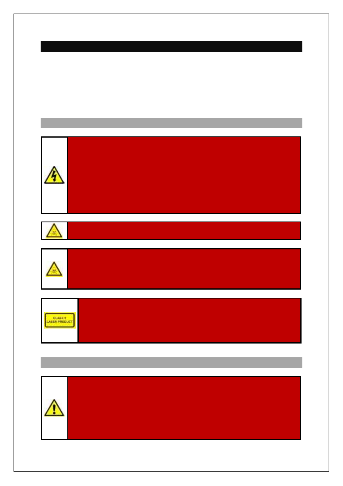
2.1 Hazards
ELECTRICALHAZARDS:
Some equipment does not have safety interlocks fitted.
Lethal single and three phase AC and DC voltages may be present when units are open
and exposed.
Before accessing any internal parts, ALL power sources to the equipment must be fully
isolated; this must include the isolation of all UPS supported supplies to the system.
MAINS VOLTAGES:
All Kelvin Hughes equipment is supplied with mains input voltage set for 220v, 50/60 Hz
ac unless otherwisestated on labels attached to the equipment.
WARNING: Some equipment contains materials which mayproduce toxic fumes if burnt.
Beryllium warning: The SharpEyeTMX and S band transceivers mounted within
the SBS-800 series are factory sealed units which contain no field serviceable
parts. The SharpEyeTMtransceivers must not be dismantled in the field as some
components within the factory sealed processor contain Beryllium which is
hazardous to health.
Class 1 laser product: There is a class 1 laser within the sealed SharpEye
transceiver processor which can represent a risk if the processor is
dismantled.
When fitted, the LAN fibre optic cable that connects to the SharpEye
transceiver and the to the MISM type 5 modules within the radar distribution
2.2 Antenna rotation warning
ANTENNA ROTATION SAFETY NOTICE:
When single and three-phase power is connected to the system and switched ON, the
antenna will rotate immediately regardless of the RUN command status.
TM
Use the antenna rotation keyswitch or man aloft safety switches to stop antenna rotation
in an emergency.
Q_`_l ni nb_ g[chn_h[h]_ m_]ncih i` nb_ ij_l[nilm b[h^\iie `il ^_n[cfm ih mnijjcha nb_
antenna and isolating a system.
KH-1602-2 issue 1: Standard SBS900 Systems Operator & Maintenance Handbook
Page 7 of 240
Page 8
SBS-900Shore Based Radar Systems
Chapter 2: Health & Safety warnings
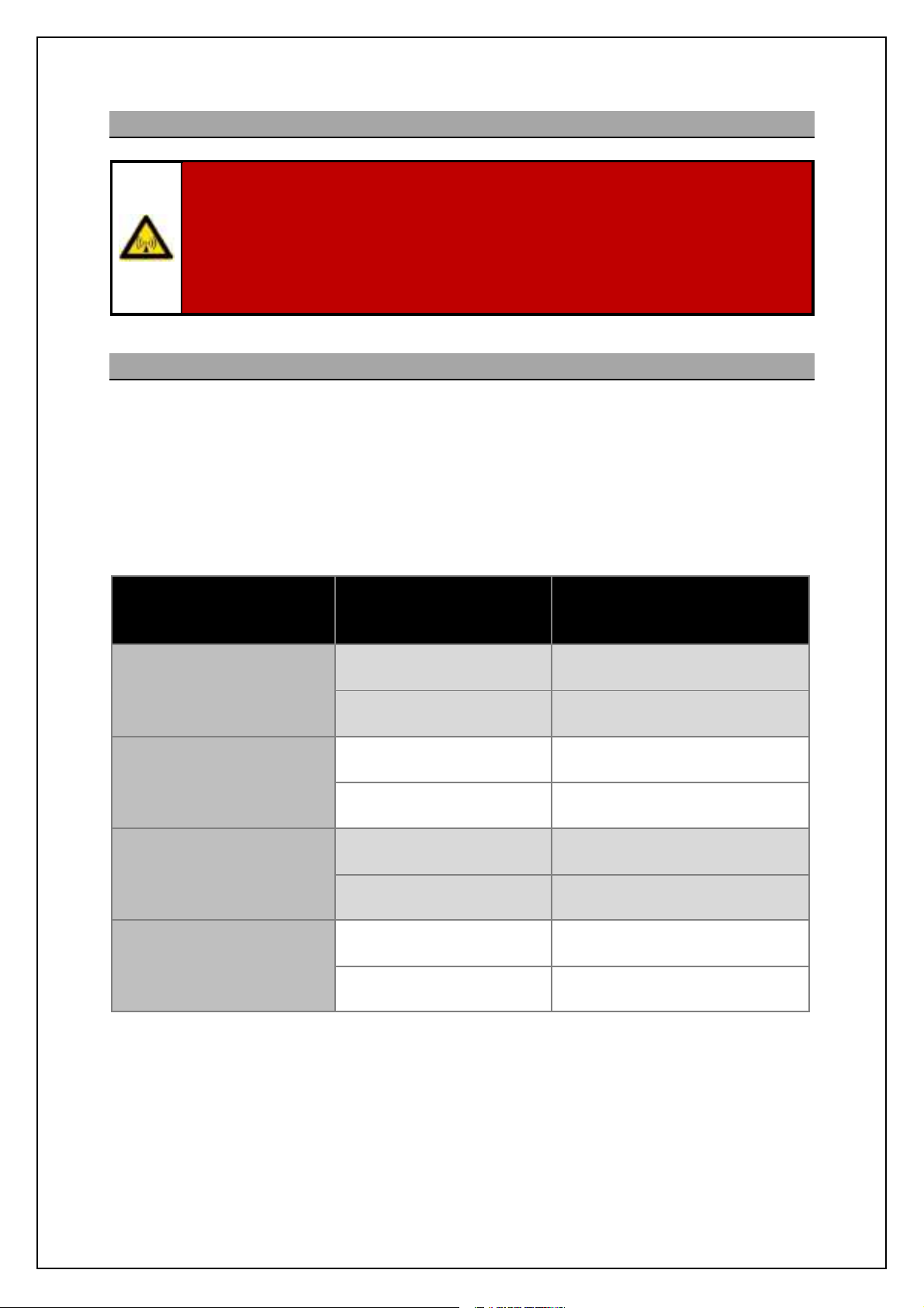
2.3 Radiation hazards
Radiation hazard: non-ionising
Avoid exposure to the main beam of a stationary radar antenna.
Avoid standing closer than 2 metres from the central front face of the antenna.
Users of cardiac pacemakers should be aware of the possibility that radio frequency
transmissions can damage some devices or cause irregularities in their operation.
Anyone using such devices should understand the risks present before exposure.
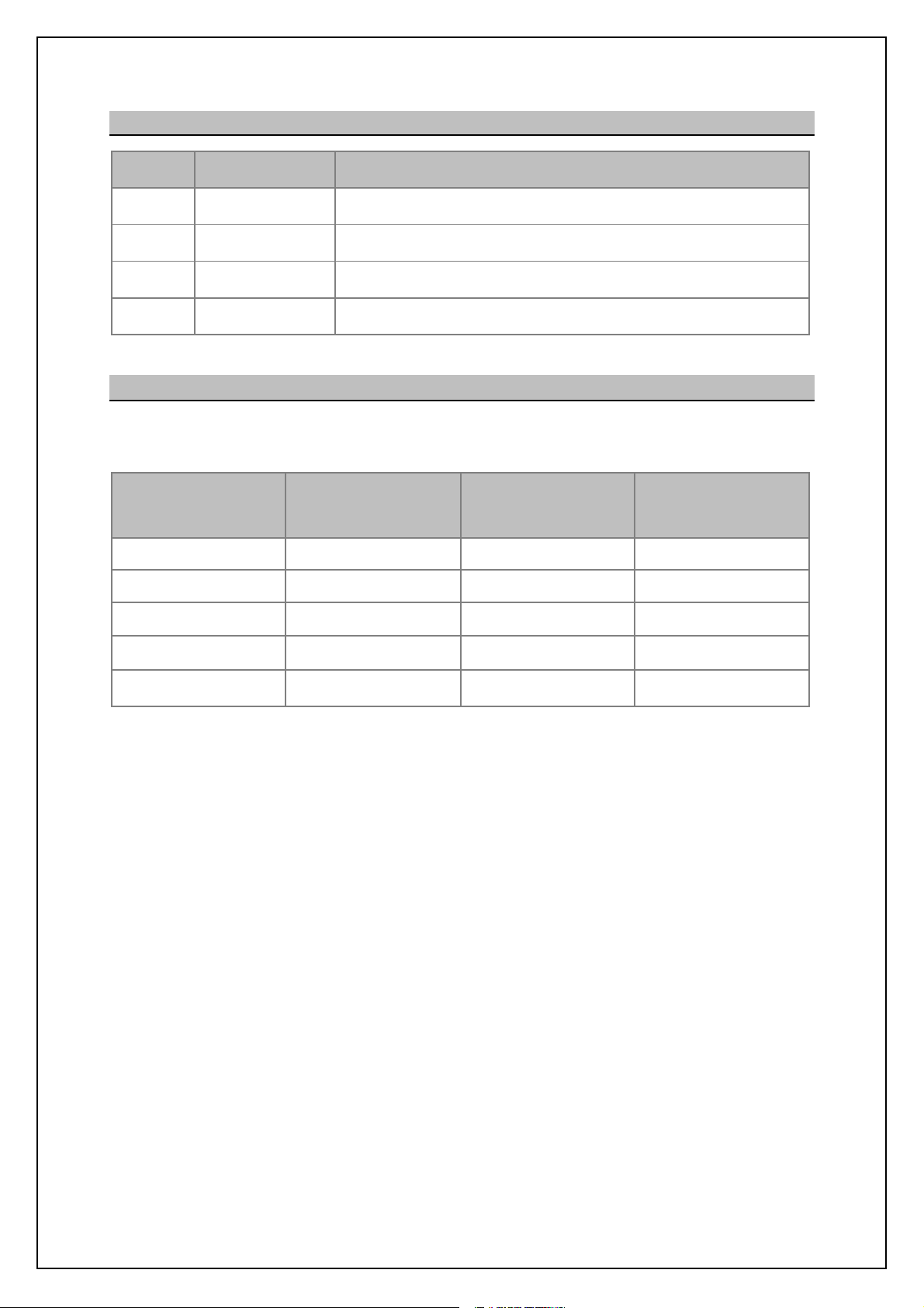
2.4 Microwave radiation levels
The Council of the European Union Recommendation 1999/519/EC (Annex III table 2) specifies the
maximum RF non-ionising field strength(power density) safe range for human exposure averaged
over a six minute period as 10W/m2in a frequency band of 10 to 300GHz.
Calculations for all SBS-900 systems show that the rotating antenna safe distance is within the
antenna turning circle although KH do not recommend any personnel to be in close proximity to a
rotating antenna due to RF exposure and the high risk of injury that can be caused by a rotating
antenna.
SBS-900 system State
X-band
Rotating antenna 1.3m
3.7m or 5.5m standard
antenna
S-band
3.9m standard antenna
X-band
Enhanced 5.5m antenna
X-band
Enhanced 6.4m antenna
Non-rotating Antenna 3.0m
Rotating antenna 1.2m
Non-rotating Antenna 3.0m
Rotating antenna 1.7m
Non-rotating Antenna 4.0m
Rotating antenna 2.0m
Non-rotating Antenna 5.0m
Range Within Which the
Power Density Exceeds
10W/m
2
The safe range for a non-rotating antenna is far greater due to the lack of averaging but this is not a
permitted operational mode and the system includes interlocks to prevent this mode of operation for a
prolonged period.
Note: 5m of waveguide is assumed.
KH-1602-2 issue 1: Standard SBS900 Systems Operator & Maintenance Handbook
Page 8 of 240
Page 9
SBS-900Shore Based Radar Systems
Chapter 2: Health & Safety warnings
2.5 Working aloft
SAFETY ALOFT:
When working aloft or near any radar scanners, moving or RF radiating equipment, ALL
power sources to the platform and equipment must be fully isolated.
Before working aloft ensure someone in authority or at ground level knows of your
intentionsand ensure that suitable clear warnings are in place.
Ensure all meansof access aloft are secureand beware of wet or slippery ladder rungs
and working areas.
All working at height health and safety requirements and procedures, including the
inspection and use of personal protective equipment (PPE), must be adhered to at all
times as advised and required by your employer, site regulations, shipyard or vessel.
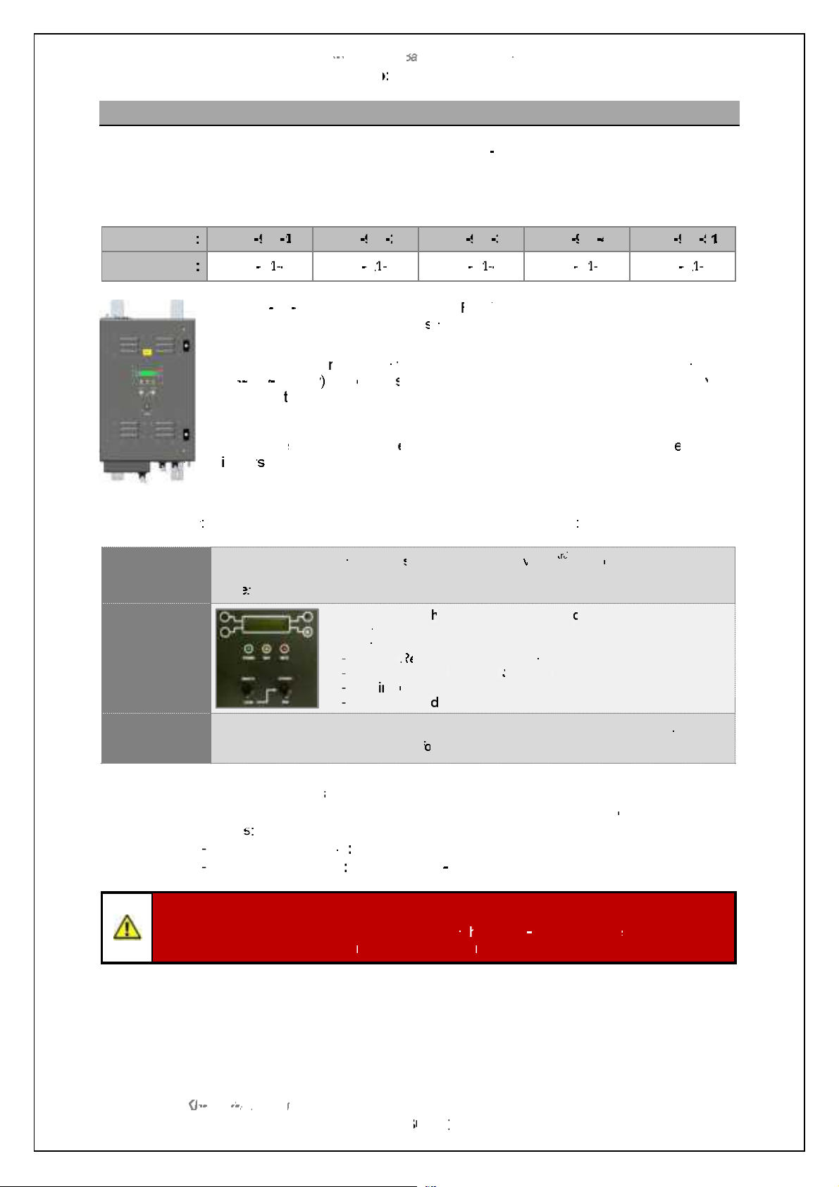
2.6 Man aloft switch/ antenna isolation.
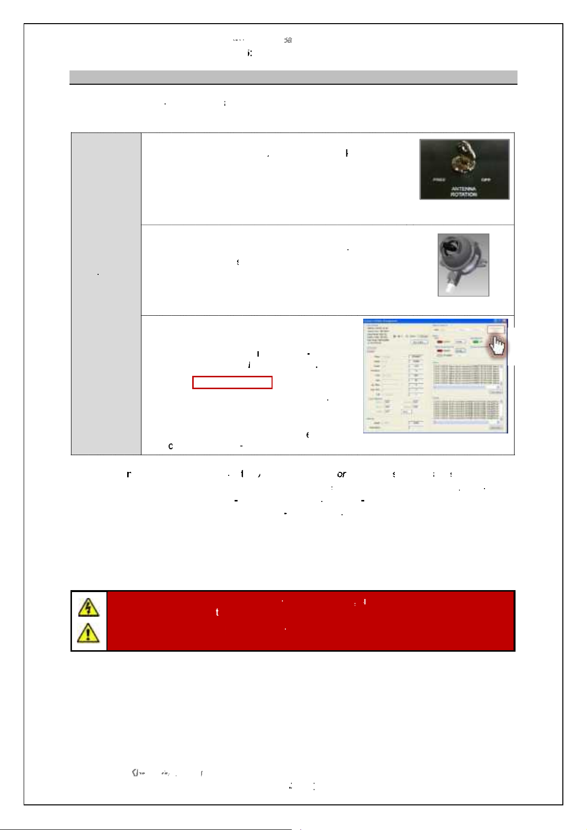
Antenna rotation and transmission can be inhibited via a Man Aloft Switch (MAS) or an r<agXaaT IAAAeXXs keyswitch. These mechanisms can be used bya person who sees a potential hazard such as a
loose halyardand decides to protect the antenna.
When activated, the reason for loss of turning is detected by the system and is reported to the local
and remote users
Safety switches
The Antenna Rotation keyswitch is located on the door of the internally mounted
Radar DistributionUnit (RDU)
Antenna
Rotation
keyswitch
Man aloft
switch
(MAS)
The Man Aloft switch, Motor ON/ OFF and Antenna Rotation keyswitch form partof a safety current
loop. This safety loop is purely hardware (no software), when the current loop is opened, AC mains
supplies to the transceivers and antenna inverter are switch OFF by use of contactors.
The key for the RDU keyswitch is captive when set to Free (enable rotation) but
can be removed when the keyswitch is to OFF.
When in the OFF position all single and 3-phase AC power to the antenna and
transceiver is isolated thus stopping antenna rotation and transmission.
The key should be removed and retained by the person who intends to enter the
potentially hazardous volume of the rotating antenna.
The man aloft switch (MAS) is designed to be installed such that it is still viewable
for the person who is carrying out maintenance tasks.
Vb_h m_n ni nb_ •OFF jimcncih the transceiver/ gearbox is isolated from all single
and 3-phase AC power thus stoppingthe antenna rotation and transmission.
Kelvin Hughes recommends that the key switches noted above are used in conjunction with the man
aloft switch but also recommend that radar users carry out a safety assessment and risk mitigation
procedure in terms of interlocks prior to approving any work on the equipment.
Full details on isolatingthe systems from the AC supplies can be found in the planned maintenance
section of the relevant systems Operator & Maintenance handbook.
KH-1602-2 issue 1: Standard SBS900 Systems Operator & Maintenance Handbook
Page 9 of 240
Page 10

2.7 Anti-static handling
CAUTION: Handling of electrostatic-sensitivesemiconductor devices
Certainsemiconductor devices used in the equipment are liable to damage due to static
voltage. Observe the following precautions when handling these devices in their unterminated state, or sub-units containing these devices:
Persons removing sub-units from equipment containing these devices must be earthed
by a wrist strap and a resistor at the labelled point provided on/ within the equipment.
' Soldering irons used during authorised repair operations must be low voltage types
with earthed tips and isolated from the mains voltage by a double insulated
transformer.
' Outer clothing worn must be unable to generate static charges.
' Printed circuit boards fitted with these devices must be stored and transported in anti-
static containers.
' Fit new devices in a special antistatic safe handling area.
' Fully isolate and mechanically disconnect all sources of AC before attaching ESD
protective wrist straps to the various points in the system.
2.8 RoHS statement
SBS-900Shore Based Radar Systems
Chapter 2: Health & Safety warnings
Restriction of Hazardous Substances (RoHS): For details on RoHS statements please contact
Kelvin Hughes; contact details can be found in at the end of this handbook.
2.9 End of life disposal
When the equipment detailed in this handbook has reachedthe end of its serviceable life, the various
parts that make up the system must be disposed of in accordance with local industrial waste disposal
regulations.
Please contact your local regulatory body for disposal instructions or contact Kelvin Hughes for a list
of any potentially hazardous material contained within the system.
SharpEyen specific disposal notice
Sb_ Rb[ljDs_x nl[hm]_cp_l(s) located withinthe transceiver enclosure are factory sealed units that
contains no field serviceable parts or lifed components.
Components within the Rb[ljDs_x jli]_mmil (all variants) contain traces of beryllium and trivalent
chromium.
Please contact Kelvin Hughes regarding the repair or a Rb[ljDs_x or its end of life disposal
instructions. Contact details for Kelvin Hughes can be found at the end of this handbook.
KH-1602-2 issue 1: Standard SBS900 Systems Operator & Maintenance Handbook
Page 10 of 240
Page 11

SBS-900Shore Based Radar Systems
Chapter 2: Health & Safety warnings
2.10 AC supplies
All AC mains poweredequipment is provided with a
power rating plate that details the power requirements
and additional information for the equipment.
The power rating plate is attached to the front cover of the
equipment and indicates the following:
- Equipment name
- Part & serial numbers
- Equipment weight
- Supply voltage & frequency range(s)
- Current ratings
- IP rating
- Product hazard warnings
AC sources: Standard SBS-900 systems require the following switched and protected AC
inputs:
' Two sources of UPS supported 2 wire 115/ 230VAC single phase
supplies + protective earth.
' 3 wire 440VAC three-phase supply + protective earth.
Example of power rating plate
Health & safety: The information found on the power rating plates must be used in conjunction
with the Health & Safety notices shown in this handbook.
Cable requirements: The AC power requirements and cable specifications can be found in the
external interfacing section of the systems installation and commissioning
handbook.
Wiring: Wiring is to be carried out in accordance with the systemmanual using the
cables defined. Please refer to the systems installation and commissioning
handbook for full details.
Disconnection devices: To comply with CE approval and EN60950 requirements it is recommended
that the AC supplies to the system are made with clearly labelled, readily
accessible disconnection devices as follows:
Single phase: Standard CE approved mains outlet sockets (not supplied).
Three phase: Class B, red, 4-pole plug & socket (not supplied).
Fuses: All accessible fusesand over current protection devices are detailed in the
corrective maintenance section of the handbook.
Replacementfuses must be of the correct type and rating.
KH-1602-2 issue 1: Standard SBS900 Systems Operator & Maintenance Handbook
Page 11 of 240
Page 12

SBS-900Shore Based Radar Systems
Chapter 2: Health & Safety warnings
2.11 Grounding/ earth points
All parts of the system must be fully and correctly connected to a proven earth point prior to
connecting any source of AC power.
The system must never be switched ON or operated with an earthing point disconnected.
Connection point: All Kelvin Hughes equipment is fitted with a single protective earth connection
point which is indicated on the mechanical installation drawings.
Conductivity tests: During installationand maintenance, the earth connections must be tested for
conductivityusing a high current impedance meter such as a Meggeror
similar.
Wrist Straps: Fully isolate and mechanically disconnect all sources of AC before attaching
ESD protective wrist straps to the various points in the system.
KH-1602-2 issue 1: Standard SBS900 Systems Operator & Maintenance Handbook
Page 12 of 240
Page 13
SBS-900Shore Based Radar Systems
Chapter 3: Software licensing and virus protection
3 Software licensing and virus protection
3.1 Software
Only approved software may be used on Kelvin Hughes equipment. The use of unapproved or
unlicensed software on any Kelvin Hughes equipment is strictly prohibited. The use of such software
voids the warranty status of the unit.
Any Kelvin Hughes designed software supplied whether pre-installed, supplied on CD/ DVDor other
removable media, is the copyright of Kelvin Hughes Ltd, which will not accept any responsibility for
any damage or losscaused in whatever way by the use or misuse of the software. This copyright
applies to software that can be supply in various formats including but not restricted to CD, DVD, USB
memory device, email or obtained via the Kelvin Hughes agents download area.
Software supplied with Kelvin Hughes equipment may not be resold or re-distributed without the
express permission of Kelvin Hughes Ltd.
3rdparty software supplied with the system such as the RadarView program remains the copyright of
the original manufacturer. See the manufactures documentation for copyright information.
3.2 Virus precautions
Many systems supplied by Kelvin Hughes Ltd including the optional Service Displays are now
PC based and it should be noted that suchsystems do not have anti-virus protection installed.
It is the responsibility of installation engineers, service engineers, maintainers and system users
to ensure that virus threatsare not transferred to the system via removable media.
WARNING: Prior to use, all removable media used on or in Kelvin Hughes products
MUST be fully scanned for viruses on a PC installed with up to date anti-virus software.
Any media containing potential virus infections must not be used.
Charges relating to systems found to be infected with a virus will be passed onto the
company found to be using removable media that has not been suitably scanned.
Note: Kelvin Hughes cannot be held responsible for damagecaused to systems
by virus infections.
Removable media referred to includes but is not restricted to USB memory sticks, USB hard drives,
`fijjs ^cm]m+ BC. CUCm [h^ [ff `ilgm i` l_gip[\f_ g_^c[-
KH-1602-2 issue 1: Standard SBS900 Systems Operator & Maintenance Handbook
Page 13 of 240
Page 14

SBS-900Shore Based Radar Systems
Chapter 3: Software licensing and virus protection
Page intentionally blank
KH-1602-2 issue 1: Standard SBS900 Systems Operator & Maintenance Handbook
Page 14 of 240
Page 15

SBS-900Shore Based Radar Systems
Chapter 4: Handbooks
4 Handbooks
The system handbook is split into two volumes that contain the following details. Additional
handbooks and technical data can be found in the handbook annexes:
KH-1602-1
Installation, Termination
and Commissioning Handbook
Contents:
1. Contents
2. Health and safety warnings
3. Software licensing & virus precautions
4. Handbooks
5. System overview
6. Equipment specifications
7. External interfacing
8. Options
9. Mechanical installation
10. Termination
11. Setting to work
12. Completion of installation
13. System acceptance test (SAT)
14. Abbreviations
15. Contacting Kelvin Hughes
16. Annex A: Antenna Sub system
17. Annex B: Supporting documentation
18. SBS-900 variants
19. Index
Note
KH1602-2
Operation and Maintenance
Handbook
Contents:
1. Contents
2. Health and safety warnings
3. Software licensing & virus precautions
4. Handbooks
5. Technical description
6. Local operator instructions
7. Remote operator instructions
8. Service display/ RadarView control
9. Planned maintenance
10. Corrective maintenance
11. Abbreviations
12. Contacting Kelvin Hughes
13. Annex A: RadarView user manual
14. Annex B: Antenna sub system
maintenance
15. Index
Note
Advanced Antenna / Antenna Turning unit (ATU):
ETahYTVgheXerf handbook: The SBS-900 series can be supplied with a range of Advanced
antennas and Antenna Turning Units.
The installation and maintenance instructions for the advanced
antennas and the antenna turning unit (ATU) are detailed in a
separate handbook located in Annex B of the Installation and
Commissioning handbook.
The Advanced Antenna Turning Unit and antenna must be installed
in accordance with the manufactures requirements which include but
are not restricted to: Health and safety, unpacking, lifting and
installation requirements.
Handbook reference: Installation and Maintenance Manual
Radar Antenna System type KAH20-AS-00000
KH-1602-2 issue 1: Standard SBS900 Systems Operator & Maintenance Handbook
Page 15 of 240
Page 16

SBS-900Shore Based Radar Systems
Chapter 4: Handbooks
Page intentionally blank
KH-1602-2 issue 1: Standard SBS900 Systems Operator & Maintenance Handbook
Page 16 of 240
Page 17
SBS
900 ShoreBased
Radar Systems
Chapter
5
Technical overview
KH
:
Page
17
of
5
Technical
overview
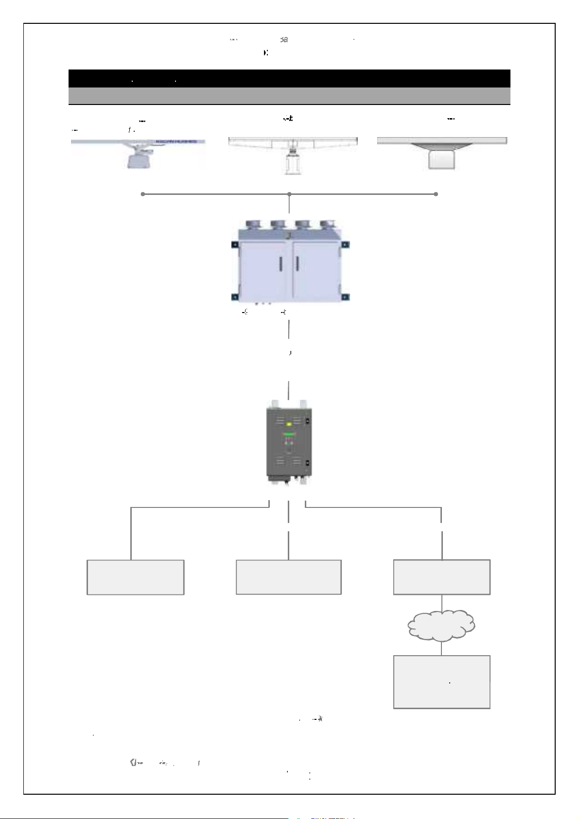
5.1
Generic
system
StandardX or S
S
Advance X
Third party X or S
installation
Antenna options
Fibre optic
Or
Cable connection
(System dependant)
Internally mounted
Radar Distribution Unit (RDU)
Serial& analoguesignals
LAN
Example of a generic
Note:
WAN
Track extractor
Optional range of
service displays
External command
and display
system
Site mains
band shown in for illustration purposes
band gearbox
band gearbox
band antenna
Third party antennainterfacing is subject to initial inspectionandcompatibility checks.
1602 2
900 system
Standard SBS900 Systems Operator & Maintenance Handbook
Page 18

Page 18 of 240
Chapter 5: Technical overview
SBS-900 ShoreBased Radar Systems
KH-1602-2 issue 1: Standard SBS900 Systems Operator & Maintenance Handbook
5.2 SBS-900 overview
Page 19

Page 19 of 240
Page intentionally blank
Chapter 5: Technical overview
SBS-900 ShoreBased Radar Systems
KH-1602-2 issue 1: Standard SBS900 Systems Operator & Maintenance Handbook
Page 20
5.3 SBS-900-1
SBS-900Shore Based Radar Systems
Chapter 5: Technical overview
KH-1602-2 issue 1: Standard SBS900 Systems Operator & Maintenance Handbook
Page 20 of 240
Page 21

5.4 SBS-900-2
SBS-900Shore Based Radar Systems
Chapter 5: Technical overview
KH-1602-2 issue 1: Standard SBS900 Systems Operator & Maintenance Handbook
Page 21 of 240
Page 22
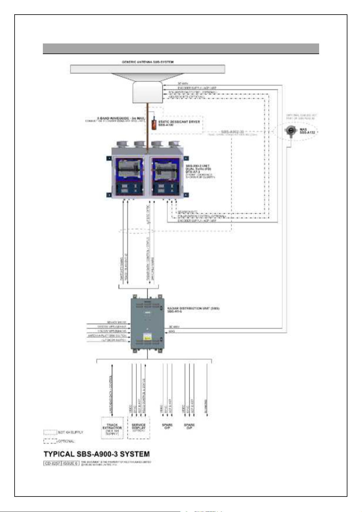
5.5 SBS-900-3
SBS-900Shore Based Radar Systems
Chapter 5: Technical overview
KH-1602-2 issue 1: Standard SBS900 Systems Operator & Maintenance Handbook
Page 22 of 240
Page 23
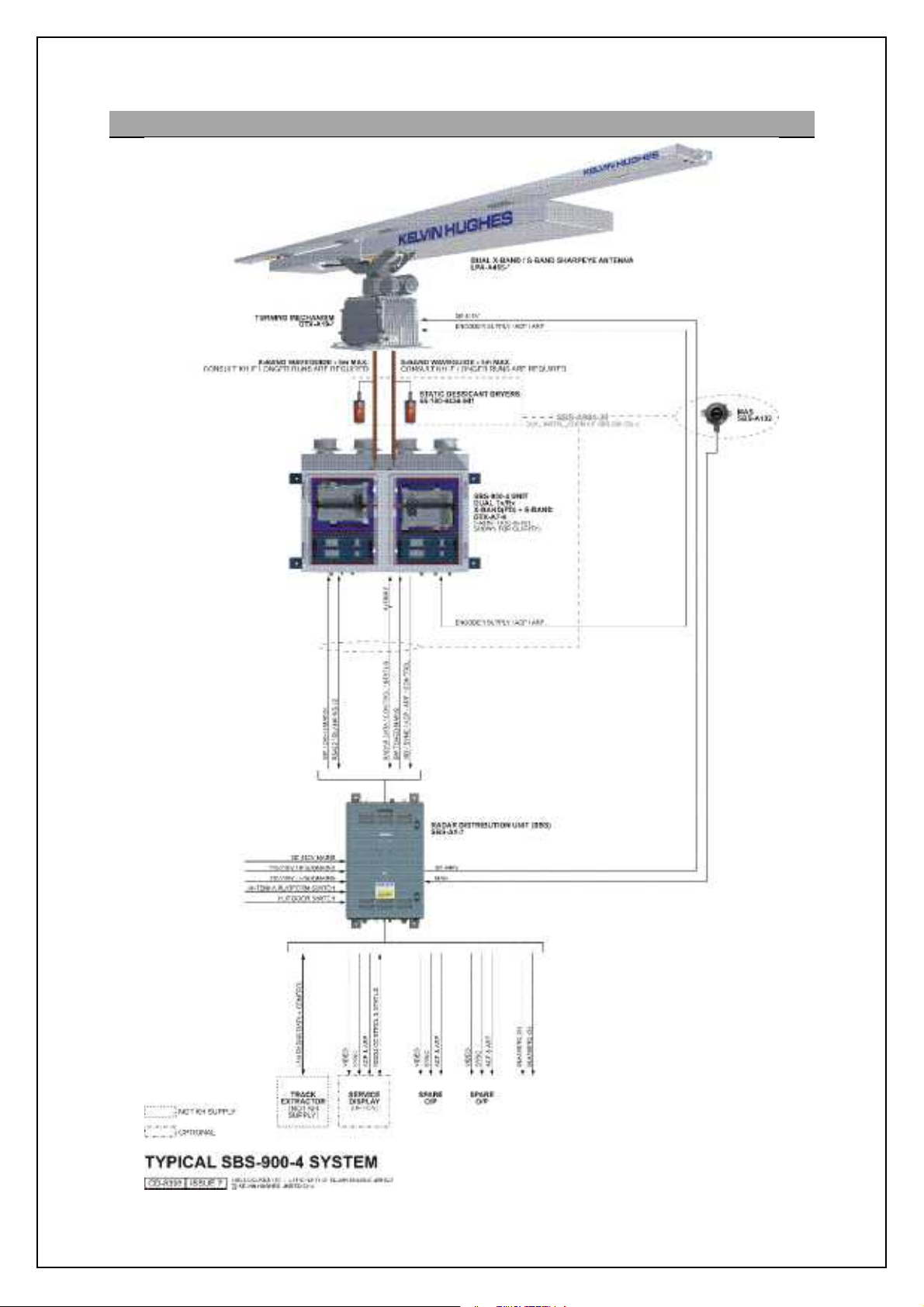
5.6 SBS-900-4
SBS-900Shore Based Radar Systems
Chapter 5: Technical overview
The LPA-A455is acombination of
the standardLPA-A55 (x-band)
and the LPA-A3(S-band) antennas
which are fitted to a DTX-A19
gearbox that has a dual rotating
joint.
The SBS-900-4 allows the operator
to select betweenX or S band
transmission.
KH-1602-2 issue 1: Standard SBS900 Systems Operator & Maintenance Handbook
Page 23 of 240
Page 24

5.7 SBS-900-51
SBS-900Shore Based Radar Systems
Chapter 5: Technical overview
KH-1602-2 issue 1: Standard SBS900 Systems Operator & Maintenance Handbook
Page 24 of 240
Page 25
SBS-900Shore Based Radar Systems
Equipment colour
Signal white RAL9003
Silver grey RAL7001
Chapter 5: Technical overview
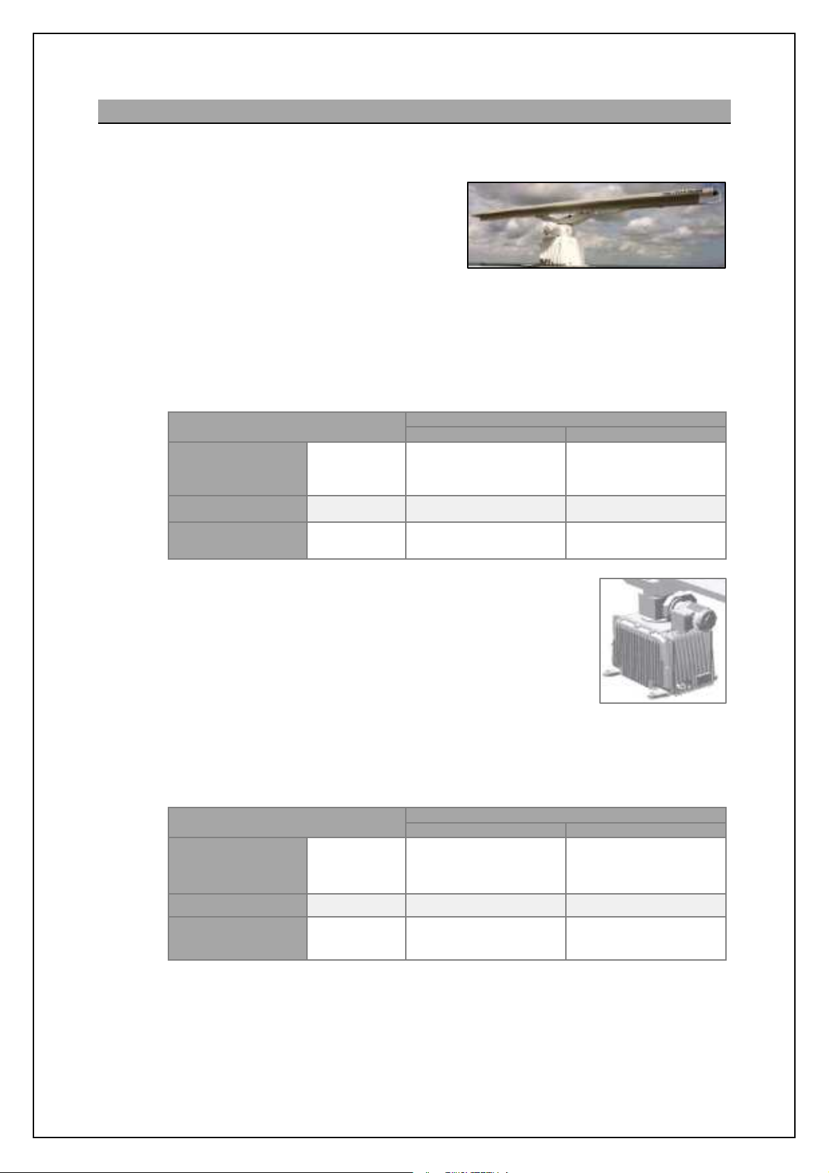
5.8 Standard antenna sub system
The standard antenna solution comprises a Kelvin Hughes manufactured gearbox and range of Low
Profile Antennas(LPA) that can be used on all variants of the SBS-900 range:
Antenna: The gearbox can be fitted with a range of X
or S-band Low Profile Antennas (LPA).
The antenna utilises polyrod technology
and a horizontally polarised end fed slotted
array enclosed in a polycarbonateplastic
case.
Single antenna: The waveguide feed from theantenna is connected to the rotating joint of
the gearbox.
Combined X & S band antenna: The waveguide from each antenna is connected to a
special dual waveguide connection at the rotating joint of the gearbox.
Example of a Kelvin HughesX-band LPA
X-band
S-band
Combined
X & S-band
SBS system
SBS-900-1
SBS-900-2
SBS-900-3
SBS-900-51 LPA-A3 (3.9m) LPA-A3-BAAA(3.9m)
SBS-900-4
Signal white RAL9003 Silver grey RAL7001
LPA-A37 (3.7m)
or
LPA-A55 (5.5m)
LPA-A455
(5.5m & 3.9m)
Gearbox: The synchronous antenna motor is driven by a 3-phase voltage
which is supplied and controlled from an inverter within the RDU.
This inverter is configured to provide a soft start and a soft stop for
the Motor and adjustable antennaRPM.
Note
Three phase power is
connected via a junction box mounted on the motor.
A DC supply from the transceiver enclosure powers the ACP/ ARP
encoder within the gearbox enclosure. ACP and ARP signals are
connected to the transceiver enclosure by cables.
The gearbox has a removable service access door that allows easy access to the ACP/
ARP connections, the encoder and the RF coupling in S-and systems. There are no other
electronics within the unit.
SBS system
Equipment colour
LPA-A37-BAAA (3.7m)
or
LPA-A55-BAAA (5.5m)
LPA-A455-BAAA
(5.5m & 3.9m)
Specifications:Full specifications on the standard antenna and gearbox range can be found in the
Note: Antennaspeeds/ RPM are factory configured.
SBS-900-1
X-band
S-band SBS-900-51 GTX-A11 GTX-A11-BAAA
Combined
X & S-band
SBS-900-2
SBS-900-3
SBS-900-4 DTX-A19 DTX-A19-BAAA
DTX-A3-AXZX DTX-A3-BXZX
installation and commissioning handbook (KH-1602-1).
KH-1602-2 issue 1: Standard SBS900 Systems Operator & Maintenance Handbook
Page 25 of 240
Page 26

SBS-900Shore Based Radar Systems
Chapter 5: Technical overview
5.9 Advanced antenna sub system
The advanced antenna solution comprises an X-band antenna and Antenna Turning Unit (ATU) that
can be used on with the SBS-900-1, SBS-900-2 and SBS-900-3 X-band systems.
Antenna: The advanced antenna sub system
comprises of a HI-gain 5.5 or 6.4m antenna
The antenna is rotated using a servo motor
at 1 RPM but can be configured during
setting to work only for speedsbetween 1
and 10 RPM.
The waveguide feed from the antenna is connected to the rotating joint of the Antenna
Turning Unit.
Antenna range Description
Example of a 6.4m advanced antenna
SBS-A55-10HW
SBS-A55-10CW 5.5 m, Circularpolarisation, white
SBS-A64-10HW 6.4 m, Horizontal polarisation, white
SBS-A64-10CW 6.4 m, Circularpolarisation, white
SBS-A55-20HW
SBS-A55-20CW 5.5 m, Circularpolarisation, white
SBS-A64-20HW 6.4 m, Horizontal polarisation, white
SBS-A64-20CW 6.4 m, Circularpolarisation, white
Note: White is according RAL 9016.For grey variants (RAL 7001) the aboveKelvinHughes part numbers
have suffix G instead of W.
10 RPM
20 RPM
5.5 m, Horizontal polarisation, white
5.5 m, Horizontal polarisation, white
Gearbox: Two Antenna Turning Units are available:
- ST1-F10 (10 RPM)
- ST1-F20 (20RPM)
Both are powered by a three-phase supply generated and controlled by a static inverter
mounted within the RDU. This inverter is configured to provide a soft start and a soft stop
for the Motor and adjustable antenna RPM.
Three phase power is connected via a junction box mounted within the Antenna Turning
Unit. The gearbox is fitted with an encoder giving 1024 @BOm [h^ 0 @QO [h^ m_lpi ginil-
A +5VDC supply from the transceiver enclosure powers the ACP/ ARP encoder within the
gearbox. ACP and ARP signals are connected to the transceiver enclosure by cables.
Note
Handbook: The installation, termination, commissioning processes and requirements for the
advanced range of antennas and the ST1-F10 & ST1-F20 Antenna Turning Unit (ATU) are
not included in this section.
Note
Please refer to Annex B or to the handbooks provided with the equipment for full
installation details.
Note: Antennaspeeds/ RPM are factory configured.
KH-1602-2 issue 1: Standard SBS900 Systems Operator & Maintenance Handbook
Page 26 of 240
Page 27
SBS-900Shore Based Radar Systems
option (SBS
-
A179).
80% of the desiccant material has changed
colour, the unit should be replaced
.
Chapter 5: Technical overview
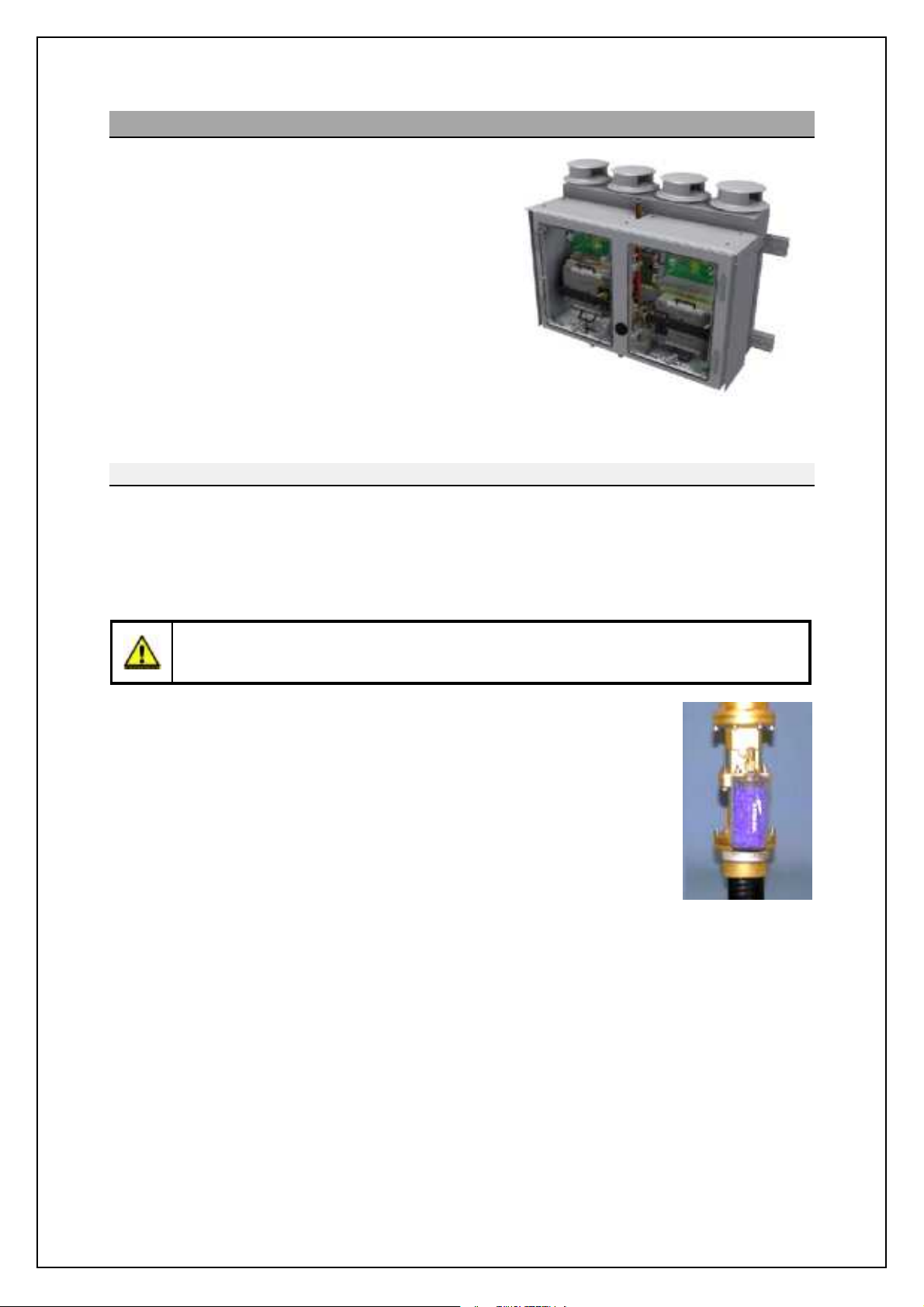
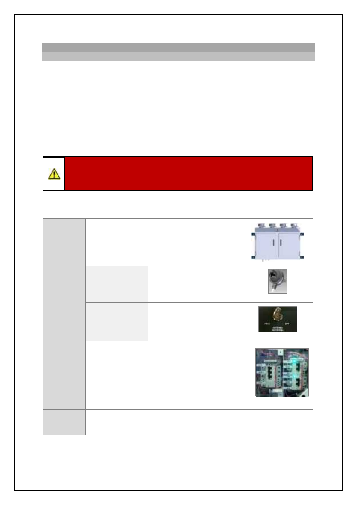
5.10 Transceiver enclosure
The DTX-A7 is a range of externalmounted
waterproof enclosures that contains the relevant X or
S-Band SharpEyeTMtransceiver(s), an azimuth signal
interface, system power supplies, a waveguide switch
(where required) and an RF connection to the antenna
sub-assembly.
The system is designedto beexternally mounted and
is convection cooled by the use of heatsinks and four
wind turned rotary ventilators mounted on top of the
assembly.
For areas operating in high ambient temperatures
additional powered cooling fans can be fitted as an
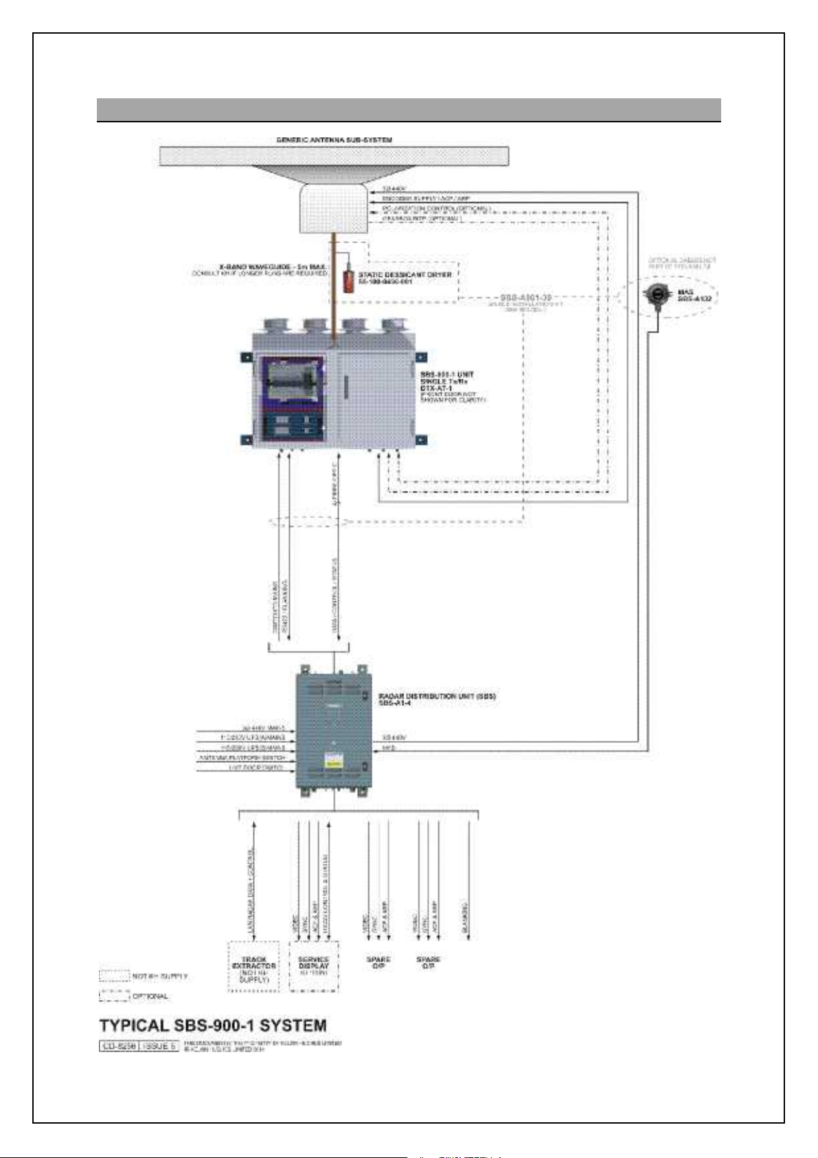
Connection to antenna
The system is connected to the antenna sub-system via a bespoke waveguide connected to the top of
the system. The waveguide/ flexwell is supplied preassembled with a static desiccator drying unit (55100-0436-001).
Example of a DTX-A7-3 shown withaccess doors
removed for clarity
Turning data (ACP/ ARP) is interfaced to the enclosure from the turning unit via cable connections.
NOTICE: Maximum flexwell/ waveguide distance
The maximum flexwell/ waveguide run between the DTX-A7 transceiver enclosure and the
antenna sub-assembly is 5 metres.
Waveguide dryer: A static desiccator is supplied pre-assembled onto the
waveguide as part of all SBS-900 systems.
The unit is a totally passive device and requires no electricalpower.
It connects directly into a gas inlet port that forms partof the flexwell/ waveguide
assembly.
The clear wall of the unit allows visual inspection of the desiccant condition. As
moisture is adsorbed the colour will change from deep blue to pink/white. When
A pressurised waveguide dryer (SBS-A131-1) is also available as an option.
KH-1602-2 issue 1: Standard SBS900 Systems Operator & Maintenance Handbook
Page 27 of 240
Page 28

SBS-900Shore Based Radar Systems
Chapter 5: Technical overview
Connection to Radar Distribution Unit
Data Signals: The following signals are transferred between the DTX-A7 enclosure and the Radar
Distribution Unit:
' Digital signals in the form of radar video, display sync, ACP and ARP
' System control, status and BITE data
' Blanking signals
Connectionsbetween the two units are via:
' SBS-900-1, -2, -3 & -4: Fibre optic cable
' SBS-900-51: Cable connection
Power: The enclosure is AC powered and controlled bythe Radar Distribution Unit. In single
transceivers a single AC supply is provided, in dual systems two AC supplies are
provided (one for each transceiver).
Internal AC-DC power supplies provide all the internal DC power requirements of the
enclosure. A DC supply is also provided to power the ACP/ ARP encoder in the
antenna sub-system.
- For Standard systems sub-systems the encoder supplyis +15VDC
- For Advanced antenna sub- systems the encoder supply is +5VDC
Over current protection devices: The Transceiver enclosure is fitted with internal breakers for the
AC supply(s) to the enclosure.
- MCB1 isolates the AC supply to the left hand side of the enclosure.
- MCB2 isolates the right hand side of the enclosure.
All breakers must be in their OFF position before commencing any form of service or
maintenance work on the system.
Access: Access to the unit is via two lockable(8mm hex key), waterproof doors mounted on
the front of the unit.
Location: The DTX-A7-X waterproof enclosure is designedto be externally mounted located
within 5 metres of the gearbox/ antenna turning unit.
Interlocks: Maintenance and ENCOM safety switches are provided via an Antenna Rotation
keyswitch fitted on the RDU and an externally mounted Man Aloft switch
Breakers for the AC input are located within the transceiver enclosure.
If no azimuth (rotation) is detected, the SharpEye will automatically switch to standby
within 60 seconds of signal loss.
KH-1602-2 issue 1: Standard SBS900 Systems Operator & Maintenance Handbook
Page 28 of 240
Page 29
SBS-900Shore Based Radar Systems
15nm (48nm)
VSWR
sensitivity
data
Chapter 5: Technical overview
K[Tec>lXn geTafVX\iXe
SharpEyeTMtransceiver technology radically departs from conventional marine navigation transceivers
through the transmission of low power RF pulses and application of pulse compression and Doppler
techniques. The technology benefits from the following:
' Solid state transmitter for high reliability ' Dynamic range of 126 dB (including sensitivity
time constant (STC) & pulse compressiongain)
' Digital pulse compression ' Minimum discernible signal (MDS) of
-125dBm
' Receiver noisefigure <5.5dB ' Internal monitoring, no external components
required to monitor operation
' Pulse Doppler processingfor improved rain
' Range discrimination: 7.5nm (24nm) and
and sea clutter rejection
Solid state technology: Solid state transistors obviate the need for a warm-up time. When the
Radar Distribution Unit is switched ON the SharpEyeTMis powered.
When a Run command is received by the transceiver, it is ready for
transmission within 40 seconds.
Output power: When transmitting, the amplifiers generate a nominal peak power of
170Watts with a maximum duty cycle of 13% at the transceiver
output flange.
System monitoring: Comprehensive built in test (BIT) facilities within the transceiver
provide on-line monitoring of the following parameters within the
transceiver:
' RF power ' Antenna system
' Temperature ' Receiver
' Power supplies
' Antenna rotation
SBS-900 Range:
Should the system detect a fault condition which could lead to early
failure of the transceiver, i.e. a high VSWR, then the transceiver
switches to a low power state which permits transmission to continue
in the short term. The built in test monitoring also ionjonm [ •Kiq QE
Oiq_l q[lhcha g_mm[a_ c` nb_ QE jiq_l ionjon `[ffm \_fiq 0// V-
Sb_ ^_mcah cm •`[cf-mi`n nb_l_\s jlipc^cha al[]_`of ^_al[^[ncih ch nb_
event of single or multiple transistor failures.
System ID
SBS-900-1 X-band
SBS-900-2
SBS-900-3
SBS-900-4
SBS-900-51 S-band
SharpEye
Transceiver
X-band
X-band
(dual redundant)
X and S-band
(dual transceiver)
TM
Doppler
& %
& &
& &
&
(X & S-band)
& %
Frequency
Diversity
&
(X-band only)
KH-1602-2 issue 1: Standard SBS900 Systems Operator & Maintenance Handbook
Page 29 of 240
Page 30
SBS
Radar Systems
Chapter
Technical overview
KH
:
Page
30
of
5.11
Radar Distribution Unit
There are 5 Radar Distribution Units used in the
standard
SBS
900
range
with the only difference
being the configuration and interfacingof the individual units.
The operation of each of the Radar Distribution Units is identical.
SBS
SBS
SBS
SBS
SBS
The SBS
A1
X Radar Distribution Unit (
is a radar processing and distribution
unit that accepts radar video input
enclosure
and
provides signal outputs in digital form.
The RDU accepts
data
SBS
900 51 only
digit
LANtothe
A
Kelvin Hughes TCP/IP specific protocol
is used
based on the Asterix format
.
The RDU al
a range of s
d
control of the
purposes.
In normal operation,
the
party
systemor track extractor
and WAN with the RDU acting as an interface.
Note
In local control, t
locally
mounted on the front of the Radar Distribution Unit (RDU); controls
include:
Local
control selection.
Local transceiver
Run
and
View
Viewing and a
A range of optionalservice displays are available which enables a maintainerto view,
controland display the radar locally f
AC Breakers:
To
AC
connections to the RDU are via clearly labelled, readily accessible
device
Single phase
supply
Standard CE approved mains outlet sockets (not supplied).
Three phase
supply
Class B, red, 4
pole plug & socket (not supplied).
Antenna Rotation Safety Notice
Depending on the status of the safety switches, w
is
connected and
switched ON, theantenna
immediately
isplay
A1
4
so provides an int
900 ShoreBased
A1
5
via fibre optic cable or cable connection (cable on
A1
6
A1
7
A1
)
system for maintenance and monitoring
8
: The RDU can be operated in either of the following modes
systemis remotely controlled
he system can be
R
Standby
ing
rd
comply with CE
command & display
may rotate
1602 2
Standard SBS900 Systems Operator & Maintenance Handbook
phase power
Page 31

SBS-900Shore Based Radar Systems
Chapter 5: Technical overview
AC requirements
Single phase: Twoindependent sources of UPS supported, single phase, 115/ 230VAC supply are
connected to the RDU.
The AC voltages are fed to an AC-DC power supply via user accessible breakers
located within the RDU. The internal power supply provides all the DC power
requirements of the RDU.
Switched AC supply is sent from the RDU to the DTX-A7 transceiver enclosure.
3-phase: A 440VAC 3-phase input is fed via a user accessible breaker to an internal static
inverter. This generates and controls the three phase requirements of the turning
mechanism solution.
Caution: When the three phase supply is connected and switched ON, theinverter
unit is powered and sendsthree-phase voltages to the antenna motor which may
rotate immediately (see safety switches).
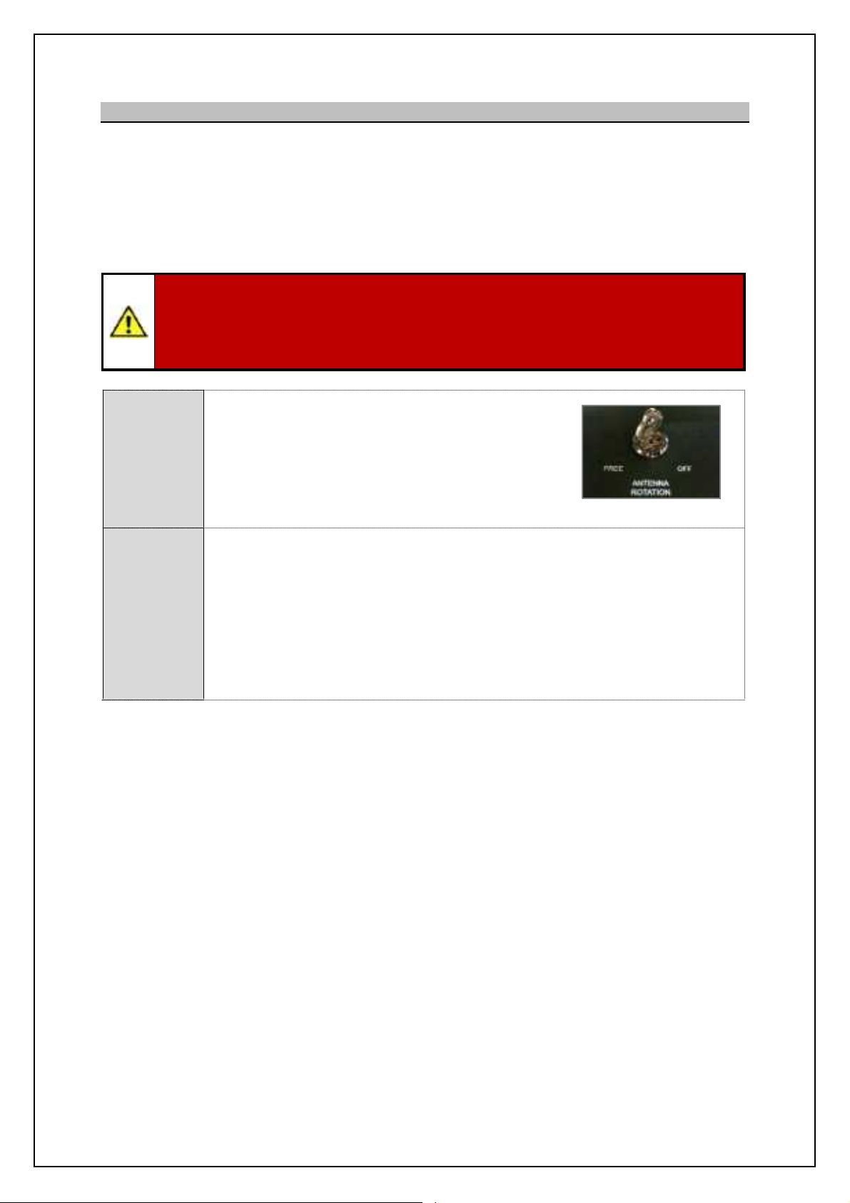
Safety switches: A normally closed safety current loop is provided for the serial connection of safety
switch contacts including an external Man Aloft switch.
Antenna rotation switch: An Antenna Rotationsafety keyswitch
is provided on the RDU andis part of the safety current loop. This
switch can beset to OFF, removed and retained by the
maintainerfor safety.
Man Aloft Switch (MAS): An externally mounted switch that can
be set to Free (rotate) or OFF.
When either the Antenna Rotation or Man Aloft switches are set
to OFF or if the safety current loop is broken/ open, the single and
3-phase AC supplies from the RDU to the transceiver enclose
and gearbox are isolated thereby stopping Antenna Rotation and
system transmission.
RDU Antenna
Rotation switch
External Man Aloft
Switch
Security Switches: There is also provision for an optional set of normally closed Antenna Platform
and a Hut Door switches that are used for monitoring purposes only. These switches
do not isolate or control any part of the system, when fitted and enabled, the systems
report the status of these switches to the RDU.
KH-1602-2 issue 1: Standard SBS900 Systems Operator & Maintenance Handbook
Page 31 of 240
Page 32

SBS-900Shore Based Radar Systems
Chapter 5: Technical overview
5.12 System control
In normal operation, the system is remotely controlled by the track extractor with the RDU
Remote
Control
Local
Control
Safety switches: The following switches are on a safety current loop which, when broken/
acting as an interface.
An optional Service Displays enables the systemmaintainer to view, control and display
the system for maintenance purposes.
In Local control, the systemcan be operated using controls mounted
on the front of the Radar Distribution Unit (RDU); controls include:
- Local or Remote control selection.
- Local transceiver Run and Standby control.
- Viewing of status and BITE data on an integrated LCD display.
- Viewing and adjustment of system configurations.
open isolate the transceiver and turning unit from the single and three-phase
AC supplies thus stopping antenna rotation and transmission.
- Antenna Rotation: A door mounted removable keyswitch to stop antenna
rotation & transmission.
- Man Aloft Switch: An externally masthead mounted switch to stop antenna
rotation & transmission.
Security switches: Hut door and antenna platform switch.
The state of these switches is reported to the track extract, service display
etc. The switches do not isolate or control any aspect of the system and are
for switch status reporting only.
KH-1602-2 issue 1: Standard SBS900 Systems Operator & Maintenance Handbook
Page 32 of 240
Page 33

SBS
900 ShoreBased
Radar Systems
Chapter
Technical overview
KH
:
Page
33
of
5.13
Unit identification
The equipment included in the SBS
900
series can be identified as follows
T
a
system should always be
for assistance or spares.
Description
Part number & serial number location
(arrow indicates label position)
Standard
low profile antenna
(all variants)
LPA
A37
LPA
A55
LPA
A455
LPA
A3
Lower
Standard gearboxes
(all variants)
DTX
A3
DTX
A19
GTX
A11
Advanced systems
Antenna and Antenna Turning Unit
(ATU)
Pleaserefer to the
handbook
supplied with the
Advanced antenna for details
Transceiver Enclosure
(all variants)
DTX
A7
Man aloft switch
SBS
A132
Radar distribution unit
SBS
A1
(
all variants)
Note
system,an additional labelis added noting
the option number
he full part and seri
(x
band)
(x
band)
band)
(x
band)
(S
band)
band)
ting Kelvin Hughes
(underside)of LPA
: If a option has been added to a
1602 2
Standard SBS900 Systems Operator & Maintenance Handbook
Page 34

SBS-900Shore Based Radar Systems
Chapter 5: Technical overview
Page intentionally blank
KH-1602-2 issue 1: Standard SBS900 Systems Operator & Maintenance Handbook
Page 34 of 240
Page 35

SBS-900Shore Based Radar Systems
Chapter 6: Local operation instructions
6 Local operation instructions
6.1 Antenna rotation warnings
ANTENNA ROTATION SAFETY NOTICE:
When three-phase power is connected to the system and switched ON, the antenna will
rotate immediately regardless of theRUN command status (see conditions below).
When three-phase AC mains supplies are connected and switched ON using the breakers located
within the RDU, the antenna may rotate immediately.
The system will only transmit when a RUN command is received from the track extractor, service
display or isset to RUN using the Localcontrols located on door of the Radar Distribution Unit.
Antenna rotation can be stopped by any of the following methods:
Antenna Rotation Switch: Place the Antenna Rotation keyswitch located on the front of the
Radar Distribution Unit into the OFF position.
Man Aloft Switch: Place the masthead Man Aloft switch into the OFF position.
RDU Breakers: Isolate the three phase AC supplies using the breaker located within
the Radar Distribution Unit.
Software Emergency Stop: Press the Antenna stop button in the service display RadarView
software (see below).
Caution: The software Antenna Stop function from theService Display MUST NEVER be
used as the primary means of system isolation for working aloft.
KH-1602-2 issue 1: Standard SBS900 Systems Operator & Maintenance Handbook
Page 35 of 240
Page 36

SBS
900 ShoreBased
Radar Systems
Chapter
6
Local operation instructions
KH
:
Page
36
of
6.2
Local control o
6.2.1
RDU
Local
controls
Radar Distribution Unit
front panel
LCD display
A backlit LCD
status,
Green
LED
Power
OFF
No power, the RDU is not switchedON
ON
The power is switched ON and the system
is
being controlled
Flashing
The power is switched ON
but
is
not controlled (no master)
Yellow
LED
RUN
OFF
The system is in standby
ON
The
has entered RUN mode
and is transmitting
Flashing
The system is unable to run because:
The
Rotation
key switc
are set
OFFposition
A fault is preventing transmission; check
the status of the unit
Red
LED
MUTE
OFF
No Mute commands are being received
the system is transmitting for a full 360
ON
The transceiver is muted
transmission)
Flashing
The system is operati
blanking applied
Switch
set to
The system is in
C
the track extractor or
r
command
&
display system.
The Standby/ RUN switch has
no function
and can be in any
position
Switches
set to
The system is in
with the transceiver in
mode.
The track extractoror
r
command
&
display system has
no control
.
Switches
set to
&
The system is in
and the transceiveris setto
RUN
The track extractoror
r
command and display system
has no control
.
Antenna
rotation
The antenna is inhibited.
All AC mains power to the
transceiver enclosure
and
antenna sub
is isolated.
The system cannot be run.
Antenna
rotation
The antenna is free to
Power is applied to the
transceiver enclosureand
antenna sub
The system is available for use.
isplay shows the system
menus, error and alarm messages
lyorRemote
(no
and is operated from
ly
the system
in the
emote
1602 2
Standby
emote
Note
emote
Note
system
system
Standard SBS900 Systems Operator & Maintenance Handbook
Page 37

SBS
900 ShoreBased
Radar Systems
Chapter
6
Local operation instructions
KH
:
Page
37
of
6.2.2
Remote
Local
switch
A
switch on the front of the
Radar Distribution Unit
allows the selection of
R
L
The following explains the basic operation of the system in these two modes.
Antenna Rotation
Warning
D
epending on the position of the safetyswitches, t
rotate regardless of the
position of the
R
emote/
L
S
R
Local
With Local selected, t
Local
control
used by the installationengineer or system maintainer to
configure, test or
l
,
W
isplay
line, system control,
status and default information can be accessed, adjusted
and viewed in the display panel which shows
status
and
defaults:
See Section
onwards
the
operation
S
switch in the
S
the SharpEye
is in a ready
state but does not transmit.
Run:
With the
Standby/ Run switch in
the
R
SharpEye
transmits.
Local
control disabled?
When the optional Service D
Local
control
is not possible as the service display has
control
For RDU
Local
control, the optional service display must be
details on Service Display operation
Remote
When Remote is selected, the system is controlled by the
externalcommand and display system
or
track extractor.
The
andl/
Service Display
control is not possible
System status and default information can still be
accessedand viewed in the display panel which shows
status
and
defaults:
See Section
onwards
the
operation
operation
tandby
tandby
TM
tandby/
switches.
optional S
he system is in
ly control the
pages 39
position, the
TM
off
line; see Service Display
tandby/
GQNJ?WGQAMLLCARCB?LBGQe
in the following section for
switch has no function
pages 39
line,
1602 2
Standard SBS900 Systems Operator & Maintenance Handbook
Page 38

6.2.3 System control status
SBS-900Shore Based Radar Systems
Chapter 6: Local operation instructions
System
status
RDU set to Local
Service display
On-line
RDU set to Local
Service display
Off-line,
Disconnected or
Switched OFF
Remote control
Remote control not
possible
Remote control not
possible
RDU
Local control
Local control at the
RDU is not possible.
In local mode, the
RDU controls the
system using the
controls on the front
of the unit.
Service display
Local control
The service display
has control of the
system.
The service display has
no control.
RDU set to
Remote
The system is
controlled by the track
extractor
Local control at the
RDU is not possible.
The service display has
no control.
KH-1602-2 issue 1: Standard SBS900 Systems Operator & Maintenance Handbook
Page 38 of 240
Page 39

SBS-900Shore Based Radar Systems
Chapter 6: Local operation instructions
6.2.4 LCD panel operation
The LCD display on the front of the RDU is a backlit, two line, 16 character display.
Push buttons located either side of the display allow the control of the setup menus, local control and
status monitoring.
The buttons are used in association with the information displayed in the LCD panel.
The bottom right button contains a warning lamp which flashes when an alarm condition is present.
Top left button
Bottom left button
6.2.5 LCD display button functions
The display menusand functions are controlled using the four push buttons located around the LCD
display.
Adjustment & selection of the various menu functions depend on the symbol adjacent to each button
as shown below:
Select menu item to the left, usually associated with the top left button.
Select menu item to the right, usually associated with the top right button.
%
&
, Select the option to the left, usually associated with the bottom left button.
Go to previous level menu, usually associated with the bottom left button.
Go to next level menu, usually associated with the bottom right button.
Top right button
Bottomrightbutton
+ Select the option to the right, usually associated with the bottom right button.
#
)
+
Move the current cursor position to the right, usually associated with the bottom left
button.
Increase the current items value.
Decrease the current items value.
-
KH-1602-2 issue 1: Standard SBS900 Systems Operator & Maintenance Handbook
Page 39 of 240
Page 40

SBS
900 ShoreBased
Radar Systems
Chapter
6
Local operation instructions
KH
:
Page
40
of
6.2.6
Alarms
When
control
and
an alarm
condition exists, the lower right button will flash
red and an audible alarm will be generated.
View alarm condition:
To view the alarm message/condition,
select the
displayed in the lower section of the LCD display.
Where present, the
symbol against
the lower right
indicates that additional alarm conditions exist. Pressing the
button scrolls through any additional alarm
messages.
Silence the audible alarm:
To silence the alarm, select the
menu and then press the lower right hand (red/ flashing) button.
The
audible
alarm will be silenced but the message will continue to
display until the conditionis cleared.
Example
In the example shown below, an X
band transceiver
is in
Local
control with a
displayedindicating that the AC mains input B has failed
fault with the power supply.
The
and
arrows allow navigation away from the alarm
messages to other functions available within the Status menu (see
section
6.6.4
onwards).
Additional alarms conditions are present as indicated by the
symbol.
The
symbol return
Example of systemstatus
with activealarms
When an
alarm has been acknowledged and more than one alarm condition exists, the display
automatically scrolls through the list of alarms.
Note1Whenthe
warning
Note2The alarm shownis an
the system is in
Note
:
pages 56
Note
and the alarm condition(s) will be
1602 2
Standard SBS900 Systems Operator & Maintenance Handbook
Page 41
SBS-900Shore Based Radar Systems
Chapter 6: Local operation instructions
6.3 Switch ON, OFF & Emergency stop
6.3.1 Switch ON
Prior to switching the system ON the following must be checked:
First time switch ON: Ensure the setting to work/ commissioning of the system has been
successfully completed and signed off.
Power: Check that all sources of external AC power are available and are switched
ON.
Antenna: Ensure the antenna is clear of all obstructions and that it is safe to rotate.
Transmission: Ensure it is safe to transmit.
ANTENNA ROTATION SAFETY NOTICE:
When three-phase power is connected to the system and switched ON, the antenna will
rotate immediately regardless of theRUN command status.
The following describes the local switch-ON sequence for the SBS-900 transmissionsystems only
and does not include the switch on procedures for the track extractor or optional service display.
DTX-A7
Transceiver
enclosure
Ensure that the AC breaker(s) located within the
transceiverenclosure are in the ON position.
Note: In normaloperation,this switch would be left in the ON position
as it is only used/ switched OFF for maintenancepurposes.
Note
Ensure that the externally
Man Aloft Switch
mounted Man Aloft Switch (MAS)
is in the FREE position.
Safety
Man Aloft Switch
Switches
Radar Distribution
Unit
Ensure that the Antenna
Rotation keyswitch on the front
of the Radar Distribution Unit is
in the FREE position.
Keyswitch on door of RDU
Within the Radar Distribution Unit KDCm qcff cffogch[n_ ih
Radar
Distribution
each breaker indicating that AC mains inputs are present
within the system.
Place all RDU breakers into the ON (UP) position.
Note
Unit
Antenna Rotation Warnng: When three phase AC mains
AC power
is present and the breakers are in the ON position, the
Radar Distribution Unit is switched ON and the antenna will
rotate (see warnings in section 6.1 page 35).
RDUAC breakers
System
available for
use
Note: The LED indicators located on power breakers are an indication that mains voltages are present. They are NOT an
indicationthatthe breakers areswitched ON.
When power is available, switched ON and the switches set as shown above, the
system is available for use and the antenna will rotate.
KH-1602-2 issue 1: Standard SBS900 Systems Operator & Maintenance Handbook
Page 41 of 240
Page 42
SBS-900Shore Based Radar Systems
Chapter 6: Local operation instructions
6.3.2 Switch OFF
Switch OFF: The following describes how to switch OFF the SBS-900 system for operation purposes.
The following does not include the switch OFF/ shut down procedures for the track extractor, optional
service display or external equipment attached to the system.
System isolation: Please refer to the maintenance section of the system handbook (KH-1602-2) for
details on isolating the system from the mains supplies for maintenance purposes or working aloft.
Caution
The following details switching the SBS-900 system OFF for operation purposes only.
The following must not be used as a primarymeans of system isolation for maintenance
procedures or working aloft.
Radar
Distribution
Unit
Safety
Switches
Radar
Distribution
Unit
AC power
Place the Antenna Rotation keyswitch on the front of
the Radar Distribution Unit into the OFF position.
This removes all AC power to the DTX-A7
Transceiver Enclosue and the Antenna sub-system
As an additional safety precaution, when in the OFF
position the key can be removed.
Keyswitchon door of RDU
Place all three breakers within the Radar Distribution Unit to the OFF position.
System status:
- The Radar Distribution Unit isswitched OFF but is not isolated from the AC
input supplies.
- The DTX-A7 Transceiver Enclosure is switched OFF thus stopping any
transmission.
- The antenna sub-system is switched OFF and will not rotate.
The LED indicators on the breakers remain illuminated.
Note
Note: The LED indicators located on power breakers are an indication thatmains voltages are present.They are NOT an
indicationthatthe breakers areswitchedON.
KH-1602-2 issue 1: Standard SBS900 Systems Operator & Maintenance Handbook
Page 42 of 240
Page 43
SBS
Radar Systems
Chapter
6
Local operation instructions
KH
:
Page
43
of
6.3.3
Emergency
stop
In an emergency,
system
transmission can be stopped using
ANY of the
followingmechanisms.
STOP
antenna
rotation
Use
any
of the
functions
shown
RDU keyswitch:
Place the
on the front of the
Radar Distribution Unit
into the
position.
As an additional safety precaution, when in
the OFF
position the key can be removed.
Keyswitch on door of
RDU
Man Aloft Switch (MAS):
P
externally mounted
masthead
Man Aloft
This has the same effect asusing the
Antenna Rotation
switch noted above.
Man
aloft switch
Service Display:
RadarView
software
When the system is being operated via the
service display
On
line)
,
select
then
Select the
Emergency
Stop
button.
This has the same effect asusing the
Antenna
Rotation Keyswitch or the Man Aloft switch.
Caution: This function is disabled wh
Servi
line.
Example of ManageRadarwindow
in RadarView
program
What happe
When
Man Aloft
or
when
the
Emergency Stop
three
DTX
A7
transceiver
enclosure
andtothe
Antenna sub
assembly
are isolated thus stopping antenna
rotatation and RF transmission.
System isolation:
Please refer to the maintenance sectionfor details on isolating the
system from the
AC
mains supplies for maintenance purposes or
working aloft.
Caution
When the emergency stop functions are used
s
voltages are still presen
The following
procedures
maintenance procedures or working aloft.
900 ShoreBased
keyswitch
switch to the OFF position.
ce Display is Off
Manage Radar
set to OFF
, single and
phase AC power to the
ingle and three phase AC
1602 2
Standard SBS900 Systems Operator & Maintenance Handbook
Page 44

SBS-900Shore Based Radar Systems
Chapter 6: Local operation instructions
6.4 Local control operational states
For the purposes of the following explanations, track extractor g_[hm nb_ om_lm ]igg[h^ [h^
display system or track extractor.
' Single and three-phaseAC supplies to the RDU are available.
' Breakers within RDUare OFF.
System
OFF
System
RUN
Safety
switches
OFF
System
configuration
System status
System
configuration
System status
' Antenna Rotation keyswitch & Man aloft switch both set to OFF.
' Remote/ Local & standby/ RUN switches on the RDU set to Remote &
standby.
' No commands being received from the Service Display.
' AC power is present within the RDU but as the breakers are in the OFF
position, the dual redundant power supply is OFF and no DC rails are
being generated.
The Radar Distribution Unit is OFF.
' Singleand three-phase mains voltages areNOT sent to the transceiver /
gearbox.
' Single and three-phaseAC supplies to the RDU are switched ON.
' The AC Breakers within RDU are ON.
' Antenna Rotation keyswitch OR Man Aloft switch set to OFF.
' Remote/ Local & standby/ RUN switches on the RDU set to Local &
Standby.
' The RDU detects that the Antenna Rotation keyswitchOR Man Aloft
switches are in the OFF position. This breaks the safetyswitch current loop.
' Thesingle and three-phase relays are opened and AC power to the
transceiver/gearbox is switched OFF.
' Antenna rotation and transmission is not possible
' The Service Display has no control over the system.
System
standby
System
RUN
System
configuration
System status
System
configuration
System status
' Single and three-phaseAC supplies to the RDU are available.
' The AC Breakers within RDU are ON.
' Antenna Rotation keyswitch & Man Aloft switch both set to FREE.
' Remote/ Local & standby/ RUN switches on the RDU set to Local &
Standby.
' The RDU is switchedON. The software readsthe condition of the Antenna
Rotation keyswitch and Man Aloft switch, detects these are in the FREE
position so makes relays within the breakers sending AC power to the
transceiver/gearbox.
' The antenna commences rotation regardless of the RUN command
State.
Note
' TheSharpEye transceiver switches ON and after a 30 to 40 second warm-
up time enters a standby state waiting for a RUN command from the RDU.
' System and BITE data from both the RDU and transceiver is available.
' Thesystem is now in standby waiting commands from the Service Display.
' Single and three-phaseAC supplies to the RDU are switched ON.
' The AC Breakers within RDU are ON.
' Antenna Rotation keyswitch & Man Aloft switch both set to FREE.
' Remote/ Local & standby/ RUN switches on the RDU set to Local & RUN.
' The RDU detects that the RDU switches are set to Local and RUN.
' The RUN command is sent to the transceiver which commences
transmitting.
' Radar signals, ACP, ARP and heading line data is sent to the radar I/O
module within the RDU.
Note:Antennarotation can be over-ridden inthe Control Defaults menu.
KH-1602-2 issue 1: Standard SBS900 Systems Operator & Maintenance Handbook
Page 44 of 240
Page 45

SBS-900Shore Based Radar Systems
Chapter 6: Local operation instructions
Transceiveroperational states
The following table shows the various operation states of the X or S-band SharpEyeTMtransceivers
within the DTX-A7 transceiver enclosure:
Operation state Description
OFF Power is not applied to the transceiver and it is switched OFF.
On completion of initialisation the transceiver switches to standby or, if any of
Initialise
Standby
the self-test checks fail, to fault state.
The system initialisation typically takes 30 to 40 seconds after which time the
system becomes available for operation.
In standby the transceiver establishes communication with the Radar
Distribution Unit and reports its status.
The transceiver receives and acts on commands from theRDU.
In Standby the antenna rotates but the system does not transmit.
Transmit
Degraded
(Low power)
Fault
When a RUN command is received from the Radar Distribution Unit and
azimuth and heading line signals are present, the SharpEyeTMtransmits.
The transceiver initially outputs at low power. The radar returns are then
processed enabling the VSWR to be checked without the risk of damage to the
transceiver.
If the VSWR is within limits then the transceiver automatically switches to full
power.
If the VSWR is high, indicating an antenna fault, a warning message is sent to
the Radar Distribution Unit and the transceiver enters the degraded Low
Power state.
The transceiver continuously runs background performance checks on forward
power, reverse power, receiver sensitivity and temperature. If any of these
parameters falls outside predetermined levels a warning message is sent to
the Radar Distribution Unit indicating the nature of the fault.
The transceiver continues to operate, but with reduced performanceand
functionality.
If the performance or functionality is degraded such that the transceiver cannot
operate it enters the fault state and a fault message is sent to the display
equipment.
The transceiver stops radiating RF and there is no video output to the Radar
Distribution Unit.
A spurious fault may be cleared by re-powering the equipment.
Communication
error
KH-1602-2 issue 1: Standard SBS900 Systems Operator & Maintenance Handbook
If communication is lost between the Radar Distribution Unit and the
SharpEyeTM, the RDU reboots the SharpEye leading to a potential 60 second
gap in coverage.
Page 45 of 240
Page 46

SBS-900Shore Based Radar Systems
Chapter 6: Local operation instructions
6.5 Switch from Local to Remote
When Localcontrol is no longer
required, the system MUSTbe
switched to Remote.
Caution: If the system is left inLocal
mode, remote operation by the
command & display system or Track
Extractor will NOT BE POSSIBLE.
Changeover: The system can only be changed from Local to Remote control using the switch on the
Radar Distribution Unit; it is not possible to remotely change from Local to Remote.
6.5.1 Set to RUN & switch to Remote
The system can beset to Remote before the track extractor is on-line or ready (see below), this may
be desirable when handing the system back to the Remote operating station.
Local
selected
Switch
to
Remote
With Localselected use the front panel or service
display to place the transceiver into RUN.
Ensure the system is transmitting and is configured as
required for operation.
Switch from Local to Remote.
The system continues to transmit and isready to accept control
commands from the command & display system or track extractor.
KH-1602-2 issue 1: Standard SBS900 Systems Operator & Maintenance Handbook
Page 46 of 240
Page 47

SBS-900Shore Based Radar Systems
Menu
Description
Chapter 6: Local operation instructions
6.6 Menus
There are four menus that can be selected from the RDU LCD display.
Menu availability depending on the position of the RDU Local & Remote switch settings as detailed
below:
RDU Menu
availability
Control
menu
Status
menu
Default
menu
Setup
menu
Local
control
Note
Remote
Control
This menu contains the operator and maintainer adjustable
parameters for the system such as range mode, Mute ON/
OFF, sea and rainfilters etc.
The current status of the system can be viewed but not
adjusted. For example signal status, transceiver run-time and
temperature figures etc.
The setup/ configuration of the system can be viewed but not
adjusted.
Sb_ R_noj g_ho cm hin [p[cf[\f_ il l_kocl_^ `il hilg[f
system operation. The menu is used by the system maintainer
or commissioning engineer to configure the system.
6.6.1 Navigating within menus
Within all RDU menu structures it is possible to move back and forward between menus
using the left and right buttons located to the side of the LCD front panel:
Range
mode
TX
power
TX
frequency
Exit
Note: In local control, the optional service display must be •iff-line to obtainthe ControlMenu.
KH-1602-2 issue 1: Standard SBS900 Systems Operator & Maintenance Handbook
Page 47 of 240
Page 48

SBS-900Shore Based Radar Systems
Chapter 6: Local operation instructions
Page intentionally blank
KH-1602-2 issue 1: Standard SBS900 Systems Operator & Maintenance Handbook
Page 48 of 240
Page 49

Page 50

is not available in normal operation and
can
only be accessed
by authorised engineers
who
commission
or maintain
the system.
within the Setup menu can reduce transceiver performance, disable functionality and/ or render the system un-operational.
Page 51

SBS
900 ShoreBased
Radar Systems
Chapter
6
Local operation instructions
KH
:
Page
51
of
6.6.3
Control menu
When operat
ing in Local mode
ontrol menu
Radar Distribution Unit
can be
operator or the system
maintainer
to
adjust
Menu availability:
The
control menu
available on the RDU when the
Local
switch is set to
off
line
When Remote is selected, the controlmenu is
not available.
When
below
can be selected and
adjusted
described in section
There is no
Incorrect configuration in the
inhibit operation. The
Control
trained technician/
6.6.3.1
Radar Source
Dual Systems:
In dual transceiversystems, radar source selects thetransceiver to be used.
SBS
900
3:
Select between Tx A or Tx B (both x
SBS
900
4:
Select between Tx A (X
band)or Tx B(S
band)
Single system:
The radar Source menu has no function in
s, the TX is
automatically selected and cannot be changed.
SBS
9001:TX A
selected (X
band)
SBS
900
2:
TX A selected (X
band)
SBS
900
51:
TX B selected (S
band)
is only
ce display is
, is not connected or is switched OFF.
is selected from the front panel, the various functions shown
Save Changes
used by the
pages 39onwards
menus can degrade the performance of the systemor
menus should only be used by a
single transceiver system
1602 2
Standard SBS900 Systems Operator & Maintenance Handbook
Page 52

SBS-900Shore Based Radar Systems
Chapter 6: Local operation instructions
6.6.3.2 Range Mode
Within the Range mode menu, the transceiver instrument range can be selected between 24 and
48nm.
24nm: Limits the transceiver to an instrumented range of 24nm. This offers twice the range
discrimination of the 48nm range.
48nm: Limits the transceiver to an instrumentedrange of 48nm.
6.6.3.3 TX Power
The output power of the SharpEyeTMtransceiver can be switched between High (default) and Low.
High power: The SharpEyeTMtransceiver transmits at full power.
This is the recommendeddefault setting.
Low power: Low power is used in close waters or in a high clutter environment where a high
output power may produce excessive unwanted reflections from buildings, bridges
and vessels.
The transceiver will utilise the standard frame pattern but with output powerreduced
to less than 40W.
Caution: As a result of reduced output power, range performance will be reduced
and the system may not meet the expected operational detection performance.
When low power isselected, a low power status is automatically generated to advise
the operator that the system is operating at a reduced output power.
Where the SharpEyeTMdetects a VSWR or a high temperature within the transceiver
the system automaticallyswitches to low power mode and generatessystem alarms.
KH-1602-2 issue 1: Standard SBS900 Systems Operator & Maintenance Handbook
Page 52 of 240
Page 53

SBS-900Shore Based Radar Systems
OFF.
Chapter 6: Local operation instructions
6.6.3.4 TX Frequency
The frequency of the SharpEyeTMtransceiver can be selected which may be necessary to reduce
interferencefrom other transceivers to obtain the best picture quality.
Seven frequency bands are available between 9.21and 9.49GHz, each band being 20MHz wide and
each band being separated by 20MHz.
6.6.3.5 Mute
The Mute function allows a 360 degree transmission inhibit to be enabled/ disabled.
Mute ON: Transmission is muted/ stopped i.e.
no RF is radiated from the antenna
however the antenna continues to
rotate.
The RED Mute LED on the front of
the RDU illuminates.
Mute OFF: The system transmits fully for 360
degrees.
The RED Mute LED on the front of is
MuteLED illuminates when Mute is enabled
6.6.3.6 Sea & rain
The level of Sea and Rain filtering can be adjusted between 000 (minimum) to 255 (maximum).
Sea: Filters the effect of sea clutter on returns.
Rain: Filters the effect of rain clutter on returns.
The levels are set usingthe + (decrease value) and , (increase value) buttons to produce the best
quality picture in the prevailing conditions.
Caution: Care should be exercised when adjusting Sea and Rain filters as reducing the
filter level can reduce signal returns from wanted / actual targets.
KH-1602-2 issue 1: Standard SBS900 Systems Operator & Maintenance Handbook
Page 53 of 240
Page 54
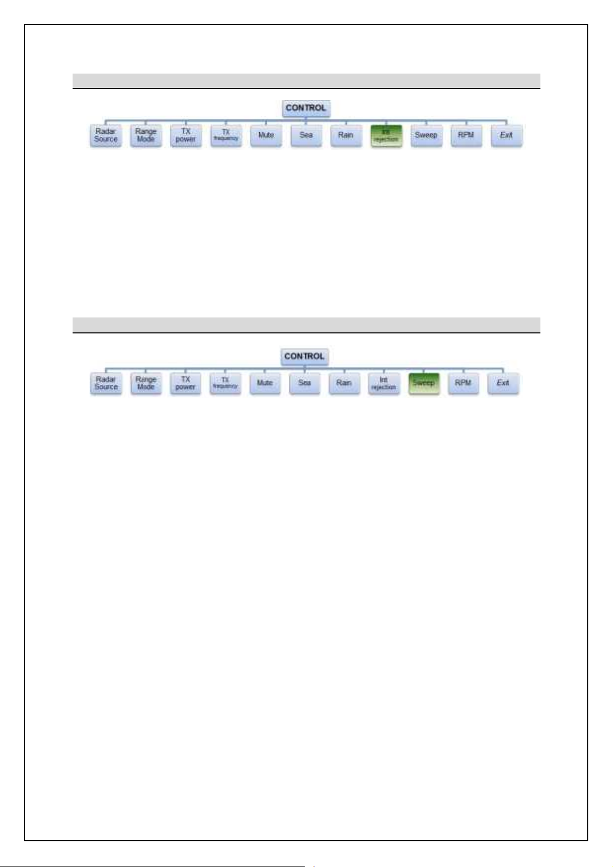
SBS-900Shore Based Radar Systems
Chapter 6: Local operation instructions
6.6.3.7 Int. Rejection
The Int. Rejection (Interference Rejection) filtering reduces the effect of in-band asynchronous
interferencefrom other radars thus reducing clutter on screen.
Int. Rejection can be enabled, disabled and configured as shown below.
Note
OFF: Interference rejection OFF/ disabled.
Lower: Select lower of adjacent traces.
Higher: Selects higher of adjacent traces.
Average: Selects the average of adjacent traces.
Note
Note
6.6.3.8 Sweep
Sweep sets the signal sweep direction of the SharpEyeTMtransceiver RF pulsesduring medium and
long pulse transmissions only.
Sweep UP: Default setting.
Sweep DOWN: This reverses the sequence of the RF pulses and may assist in the reduction
of in-band asynchronous interference from other radars in the same Locality
thus potentially improving the quality of returns.
Note: HigherandAverage interference rejection modes cannot be selected, these are for future developments
KH-1602-2 issue 1: Standard SBS900 Systems Operator & Maintenance Handbook
Page 54 of 240
Page 55
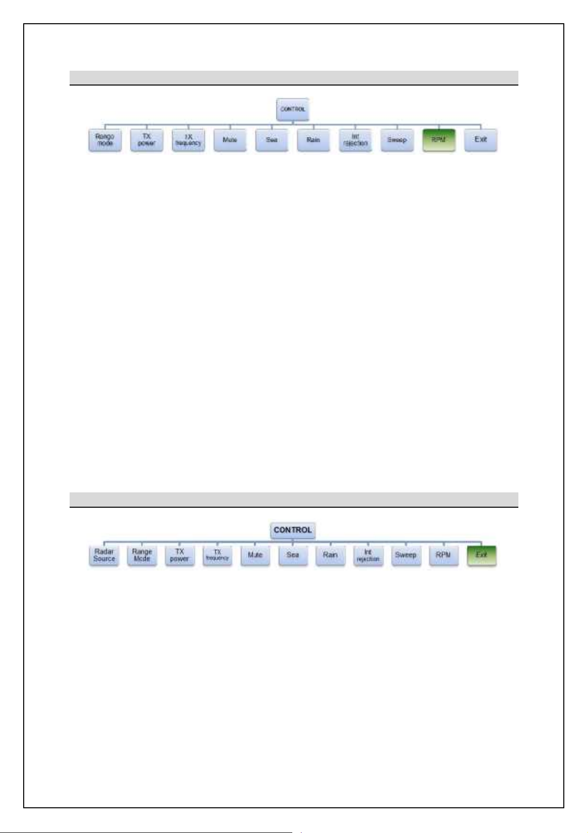
6.6.3.9 RPM
SBS-900Shore Based Radar Systems
Chapter 6: Local operation instructions
The RPM function allows the operator to stop rotation (OFF), select auto or one of three pre-defined
antenna rotation speed.
Note 1
- Antenna speeds are configured at the factory and are enabled or disabled during setting to work.
- The RPM value set by selecting low, normal and high cannot be configured by the operator.
- Depending on the system configuration, different antenna speeds may not be available.
Auto: Automatically selects the optimum antennaRPM for the range mode in use.
OFF: Antenna rotation is stopped.
Note 2
Note 1
Low: Whereenabled, the low antenna rotation speed configured during setting to work can
be selected.
- Low speeds increase the probability of target detection whilst reducing the update
rate.
Normal: The standard antenna rotationspeed configured during setting to work can be
selected.
- Normal speed offers the best overall detection performance.
High: Where enabled, the high antenna rotation speed configured during setting to work
can be selected.
- High speeds increase the update rate whilst reducing the probability of detection.
6.6.3.10 Exit controlmenu
Selecting Exit closes the Control menu and returns the display to the default menu.
There is no Save Changes button or function, any adjustments are immediatelyadopted.
Note 1: Antenna speed selection is system dependant and is notavailable on all models. Please consultwithKelvin Hughes
for additionaldetails.
Note 2: Setting theantenna speed to OFF in the RPM menu must NOT be used as a primary means of isolating the antenna
and its sub-systemsforsafetycritical purposes.
KH-1602-2 issue 1: Standard SBS900 Systems Operator & Maintenance Handbook
Page 55 of 240
Page 56

SBS
Radar Systems
Chapter
6
Local operation instructions
KH
:
Page
56
of
6.6.4
Status menu
The
Status menu
on the
Radar Distribution Unit
is used by the
operator or the system
maintainer
to
view
but not configure or adjust
the current system settings.
TheSmenu
is available on
the RDU
in both
and
setting.
or
When
is selected from the front panel, the various functions shown below can be selected and
viewed
6.2.4
39
onwards
6.6.4.1
System status
When the status menu is initially selected the system status is shown
with any active alarms.
In the example shown below, an X
band tr
Local
control with a
displayed indicating that the AC
mains input B has failed, is switched OFF or there is a fault with the
power supply.
The
symbol against
the lower right
alarm conditions exist. Pressing the
button scrolls through these
alarms.
Example of system status
with active alarms
ALARMS
will sound.
To silence the alarm, select the
lower right
audible alarm will
stop howeverthe
Where an alarm has been acknowledged and more th
automatically scrolls through the list of alarms.
See section
6.2.6
for additional information on alarms.
Note:
900 ShoreBased
pages
Note
: When an alarm condition exists,the lower right button will flash red and an audible alar
tatus menu and press the
page 40
The alarm shown in the example may not be a
1602 2
Standard SBS900 Systems Operator & Maintenance Handbook
Page 57
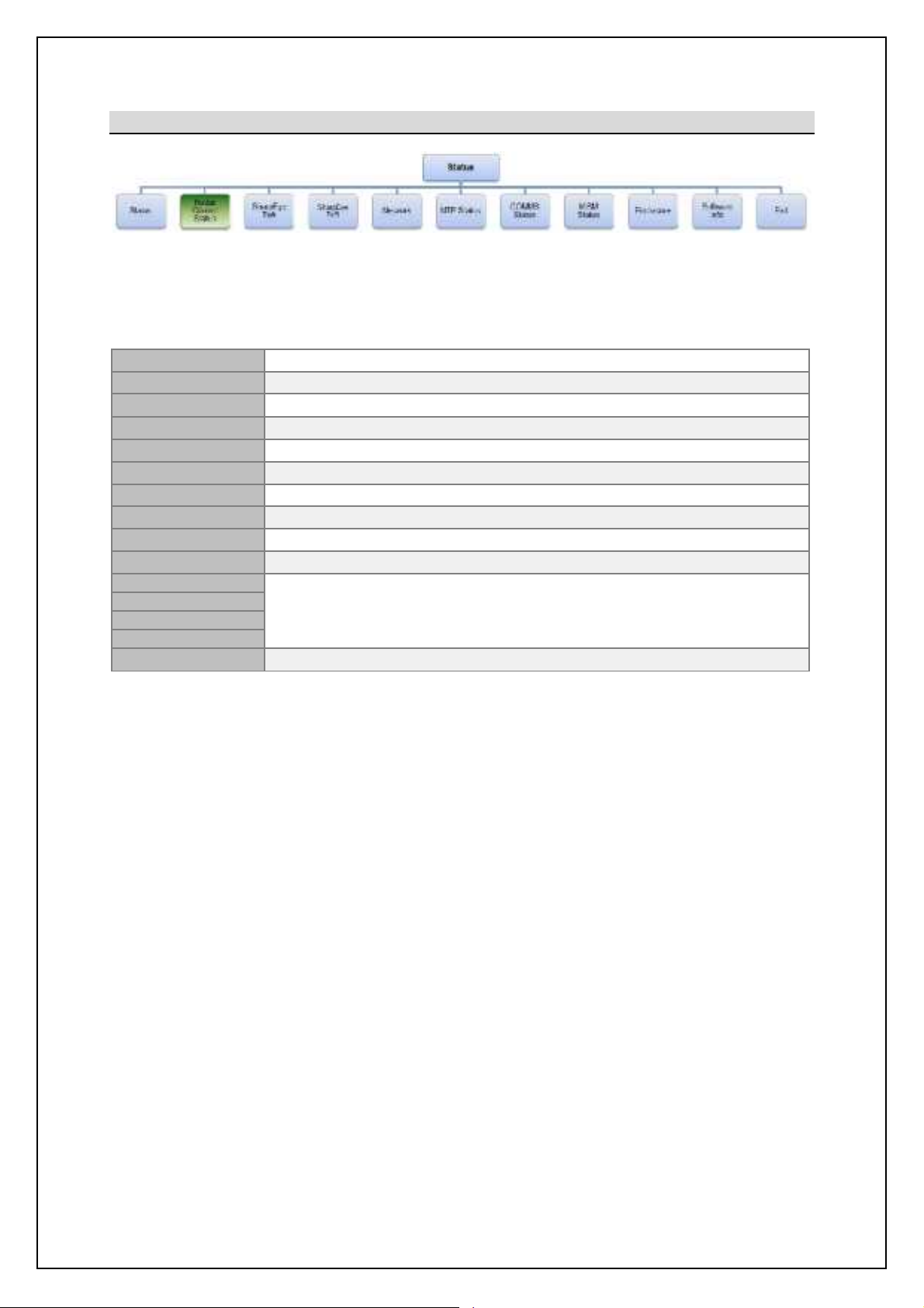
SBS-900Shore Based Radar Systems
min.
max.
min.
max.
Rel sector 1
Rel sector 2
Rel sector 3
Rel sector 4
Chapter 6: Local operation instructions
6.6.4.2 Radar Control Status
By scrolling through the Radar Control Status menus, the following system configurations and settings
can be viewed but not adjusted.
A full description of eachfunction is shown in the Control menu section 6.6.3 pages 51 onwards.
Radar Source Transceiver A or B selection in dual systems
Range mode Current instrumented range of 24nm or 48nm.
TX power Rb[ljDs_x ionjon jiq_l i` Kiq il bcab-
TX frequency Shows which of the 7 SharpEyeTMtransmission frequencies is selected.
Mute Indicates if the Mute is switched ON or OFF.
SEA Shows the configured value of the Sea filter (000
RAIN Shows the configured value of the Rain filter (000
Int rejection Shows if interferencerejection is set to OFF or Lower.
Sweep Shows if the sweep is set to Forward (default) or reverse.
RPM Shows the selected speed (revolutions per minute) of the antenna motor.
to 255
to 255
).
).
Rel sector 1 to 4 will show Enabled or Disabled for each blanking sector.
When Enabled, the start/ stop bearings of the selected sector is also shown.
Exit Exits the Radar control status menu.
KH-1602-2 issue 1: Standard SBS900 Systems Operator & Maintenance Handbook
Page 57 of 240
Page 58

SBS-900Shore Based Radar Systems
SBS
-
900-1
Single
X-band
N/A
SBS
-
900-2
Single
X-band
N/A
SBS
-
900-3
Dual
X-band
X-band
SBS
-
900-4
Dual
X-band
S-band
SBS-900-51
Single
N/AS-
band
is
present. The normalvalue is 4096.
present
.
Status 0: Mode
Run Mode
Standby or Run
.
Range
24nm or 48nm
.
Sweep
Forward or reverse
.
RPM
Shows the
RPM as detected by the SharpEye
TM
Video range
Show the instrumented video range in
µs.
Status 1: Alarm
RX
ReceiverOK or
F
ail
.
automatically switches to low power mode
.TX power
Output power OK or
F
ail.PLO
Programmable
Local
oscillator OK or
F
ail.SYNTH
SharpEye
TM
internal synth OK or
F
ail.Temp
Internal temperature OK
, warning or
shutdown
.
Turning
Antenna t
urning data OK or
F
ail.HL
Heading line
(ARP)
OK or
F
ail.AZ IN
Azimuth in
(ACP)
OK
, reverse
orFail.FPG
A2
FPGA 2 OK or
F
ail.
Status 2: GSR
Sea
Sea clutter: 000 (minimum) to 255 (maximum)
.
setting
.
Doppler filter
Select levels of 4, 8, 16, 32 or 64
.
Chapter 6: Local operation instructions
6.6.4.3 SharpEye
By scrolling through the SharpEye Tx A or SharpEye Tx B menus (see table below), the following
transceiverconditions can be viewed but cannot be adjusted.
Note: In Single transceiver systems,the Tx A or Tx B menu may not be available.
System Transceivers TX A Tx B
SharpEye HL Shows the antenna RPM based on HL frequency.
Azimuth
Shows the value of the azimuth being received or Fail if no signal
Video Shows if the video is OK (present) or Fail if no signal is present.
Sync
Shows the current Sync value (PRF) or Fail if no signal is
Blanking Shows if blanking is OK (present) or Fail if nosignal is present.
&
Mute ON or OFF.
Frequency SharpEyeTMtransmission frequency (1 to 7).
Power High or Low.
25us Pre sync
Pre-sync from the SharpEyeTMtransceiver
Enabled or Disabled.
&
VSWR
VSWR OK or Fail ~ if Fail the transceiver
KH-1602-2 issue 1: Standard SBS900 Systems Operator & Maintenance Handbook
&
Rain Rain clutter: 000 (minimum) to 255 (maximum).
Int Rej Shows the current Interference Rejection
Continued on following page
Page 58 of 240
Page 59

SBS-900Shore Based Radar Systems
continued
VERS
FPGA version
Version of code loaded into the FPGA
.
switched ON
(HH:MM)
.
Status 8: Temp
FPGA 1 temp
The current temperatureof FPGA 1 (Deg. C)
.
FPGA2 temp
The current temperatureof FPGA 2 (Deg. C)
.
Exit the SharpEye Tx A or Tx B menu
Temp
Shows the temperature in Degrees C.
Range Limit
TBC
Video Timing
TBC
Video reports
TBC
Local SAC SIC ID
TBC
Destination SAC SIC ID
TBC
IP Address
TBC
Gateway Address
TBC
Dest Address
TBC
MTU size
TBC
MAC Address
TBC
Chapter 6: Local operation instructions
SharpEye
(
Status 3: VERS & ZM number System software identification number.
)
Software
Status 5: Times & Time-ON
Run-time
The version number of the aboveZM number.
Number of hours the SharpEyeTMhas been
Number of hours the system has been
transmitting (HH:MM).
&
Exit
6.6.4.4 Network
The IP addresses and network status can be viewed but not adjusted.
Note: In some configurations,the menuwill not be present.
Netmask Address TBC
Control Port TBC
Fragment TBC
Exit Exit the Network menu.
KH-1602-2 issue 1: Standard SBS900 Systems Operator & Maintenance Handbook
Page 59 of 240
Page 60

SBS-900Shore Based Radar Systems
IP Address
TBC
NTP Port
TBC
Time (hh:mm:ss)
TBC
Exit
Exit the Network menu.
SBS
-
900-1
Single
X-band
N/A
SBS
-
900-2
Single
X-band
N/A
SBS
-
900-3
Dual
X-band
X-band
SBS
-
900-4
Dual
X-band
S-band
SBS-900-51
Single
N/AS-
band
Note 1
SharpEye TX
-BThe transceiver is active or inactive
Note 1
Comms S/E A1
TBC
Comms S/E B1
TBC
TE display
Track Extractor (TE) is active or inactive
Note 2
Service display
Service display is active or inactive
Note 2
Network Card
TBC
Enclosure
TBC
Exit
Exit the Comms status menu
Chapter 6: Local operation instructions
6.6.4.5 NTP Status
The IP addresses and network status can be viewed but not adjusted.
Note: In some configurations,the menuwill not be present.
Time Stamp TBC
6.6.4.6 COMMS status
By scrolling through the COMMS status menus, the following system conditions can be viewed but
cannot be adjusted.
System Transceivers TX A Tx B
In the following Active/ Inactive means:
Active: A correctly configured and connected system is switched ON and sending serial
command or status request messages.
Inactive: A correctly configured and connected system may be switched OFF or is not sending
serial messages.
SharpEye TX-A The transceiver is active or inactive
Note 1: Ifcommunication between the RDU and the transceiver is lost, the RDU carries out a single power reset to the
transceiver (cycles the AC mains). If communication is not re-established the COMMS status will show Inactive.
Note 2: Arequest status from the track extractoror optional service display is not necessary when in the Control menu.
KH-1602-2 issue 1: Standard SBS900 Systems Operator & Maintenance Handbook
Page 60 of 240
Page 61

SBS-900Shore Based Radar Systems
A1 MISB 5
B1 MISM 5
A2 MISM 5
B2 MISM 5
A3 I/O Mk2
B3 I/O Mk2
A4 I/O Mk2
B4 Signals
A5 Signals
B5
Comms
A6 Signals
B6 I/O Mk2
MISB
PSU
Exit
Exits the MISM status menu
Chapter 6: Local operation instructions
6.6.4.7 MISM status
By scrolling through the MISM status (Modular Interface System Module) menus, the status of
each of the 12 slots on the backplane can be viewed.
Possible MISM conditions:
Empty: A PCA is not fitted in the slot.
Error: The PCA is in the wrong slot for the RDU variant.
Missing: The PCA required by the software is not present i.e.
is not loaded.
Present: The correct PCA is fitted.
Error messages: If a module is fitted in the wrong slot or is missing,
the RDU will not function further than reporting the
error.
KH-1602-2 issue 1: Standard SBS900 Systems Operator & Maintenance Handbook
Page 61 of 240
Page 62
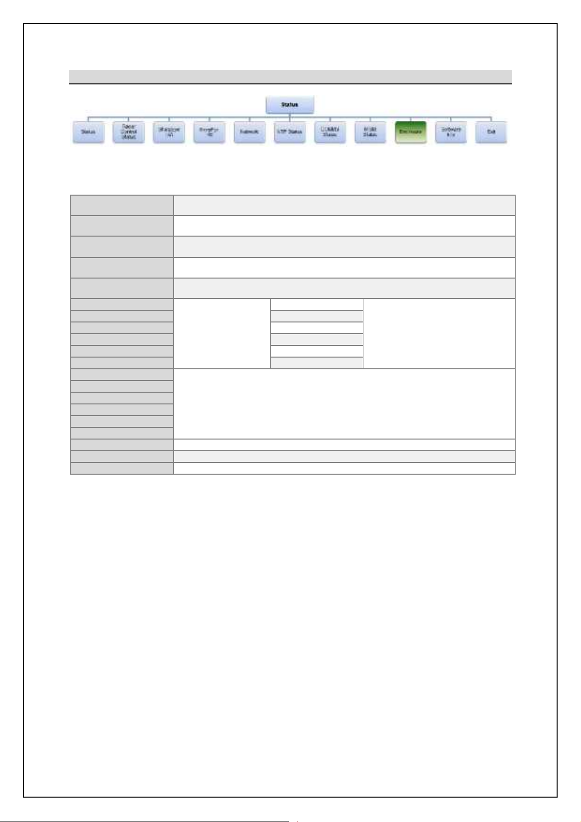
SBS-900Shore Based Radar Systems
Note:The temperature sensor is located on SBS
-
A126PCA.
Note:Advanced antennasubsystems only.
Note:Advanced
antennasubsystems only.
Fan A1
Status of Fan A1
Fan A2
Status of Fan A2
Fan A3
Status of Fan A3
Fan B1
Status
of Fan B1
Fan B2
Status of Fan B2
Fan B3
Status of Fan B3
PSU Tx A: 3.3V
PSU Tx A: 15V
PSU Tx A: 13V
PSU Tx B: 3.3V
PSU Tx B: 15V
PSU Tx B: 13V
PSU INT: 15V
Indicates the power supply voltage.
PSU INT: 5.0V
Indicates the power supply voltage.
Exit
Exits the Enclosure menu
Chapter 6: Local operation instructions
6.6.4.8 Enclosure
The status of the transceiver enclosure and optional antenna sub-assembly monitoring can be viewed
in the Enclosure menu.
Encl Temp
Oil level MON
Oil Temp MON
ENH Encoder
WG / FIB / POL
Internal temperature of the transceiver enclosurein Degrees C.
Status of theoptional oil level monitoring
Optional Oil Temperature status
Note:Advanced antennasubsystems only.
Shows if an enhanced encoder is enabled or disabled
Note:Enabled for Advanced antenna sub systems only.
Shows if a polarised antenna is enabled.
Optional SBS-A179
Powered Fan
assembly
Note: In single transceiver systems. Fan
bank A or B may not be present in the
menu structure.
Indicates the power supply voltage.
Note: In single transceiver systems Tx Aor Tx B voltages may not be present in the menu.
KH-1602-2 issue 1: Standard SBS900 Systems Operator & Maintenance Handbook
Page 62 of 240
Page 63

SBS-900Shore Based Radar Systems
MISB
Backplane
MISB FPGA number
SharpEye
Tx A
S/W
SharpEye
Tx A
FPGA
SharpEye A1 Software
SharpEye A1
FPGA
SharpEye B1 Software
SharpEye B1 FPGA
SharpEye B2 Software
SharpEye B2 FPGA
SharpEye B Software
SharpEye B FPGA
Network Software
Enclosure
Exit
Exits the Software Info menu.
Chapter 6: Local operation instructions
6.6.4.9 Software info
By scrolling through the software info menus, the various software versions for the system can be
identified:
These menus display the software part and version umbers loaded into
the system.
6.6.4.10 Exit Status menu
Selecting Exit closes the status menu and returns the display to the default menu. As no changes can
be made, there isno Save Settingsfunction.
KH-1602-2 issue 1: Standard SBS900 Systems Operator & Maintenance Handbook
Page 63 of 240
Page 64

SBS
Radar Systems
Chapter
6
Local operation instructions
KH
:
Page
64
of
6.6.5
Default and
Setup
menu
Depending on
the
system status
front panel will show
Defaults
or
Setup
Default:
This is the normal operational setting and is u
maintainer to view the system configurations
(read only)
Setup:
When configured for commissioning,
technician or system maintainer
for
configur
setting to work.
The
Setup menu is
not used during normal operation.
Description:
The basic outline of the menu is detailed on the following pages. Detailed
explanat
ions for eachsetting can be found in the
S
system Installation and Commissioning handbook (reference KH
1602
Menu variations:
The menu structure can vary depending on the system variant selected. For
example in a single X
band system, the
and
Fan Band B
menus
are not present.
Default m
(normal use)
When the servicedisplay is
inactive
line)
, t
is available
Local
Settings in the
D
efault menus
be viewed but
be adjusted.
or
Setup menu
)
The
Setup
is only available when the
service display is offline, the
switch is set to
and
the RDU is configured to be commissioned.
not used
and setting to work of the SBS system.
Incorrectconfiguration in the setup menus can the system
performance
operation.
must
only be used by a suitably
system
maintainer.
900 ShoreBased
etting to
1).
(off
in normal operation as it allows thecommissioning
1602 2
Standard SBS900 Systems Operator & Maintenance Handbook
Page 65

SBS-900Shore Based Radar Systems
+
i.e.
SBS-900-1
CAN Address
To Be Confirmed
.
WG dryer
Enable
d when the optional
pressurizedwaveguide dryer is
i
nstalled.
Horizontal POL
Vertical POL
Note:In
singleTransceiver systems,this menu may not be present.
Note:In single Transceiver systems,this menumaynot be present.
Note:In single Transceiver systems,this menumaynot be present.
Maximum FREQ
Displays
nb_ g[rcgog [p[cf[\f_ Rb[ljDs_x `l_ko_h]s
.
High RPM
Enabled when HIGH RPM antenna speeds have been commissioned.
Note: System
specific menu, this may not be present in standard system.
EXIT
Exits the Variant Options Menu
.
Service port
Displays the Baud Rate for the Service Display.
TX/ TX B
Ccmjf[sm nb_ A[o^ Q[n_ `il nb_ Rb[ljDs_x SW . Qr A-
EXIT
Exits the Serial Ports menu
Chapter 6: Local operation instructions
6.6.5.1 Brightness
Brightness is used to set the backlight brilliance of the LCD front panel on the Radar Distribution Unit.
Bright
Bright -
Increases the backlight brillianceof the front panel.
Decreases the backlight brilliance of the front panel.
6.6.5.2 Variant Options
The Variant Options menu shows the system configuration.
SBS variant Shows the SBS system number
CAN Mode Shows the CAN mode as OFF,RIU, TIU or Fixed.
TX PSU CONT Set to Always ON in SBS-900 systems.
Days to Swap
Door switch Enabled where a Hut door security switch is connected.
Platform switch Enabled where an Antenna Platform security switch is fitted.
Circular POL
Anti-clock POL
ENH Encoder Fitted is displayed when an enhanced encoder is installed.
Oil status
Fan Bank A
Fan Bank B
Active Fan
Reserve Fan
Minimum FREQ Displays nb_ gchcgog [p[cf[\f_ Rb[ljDs_x `l_ko_h]s.
Showsthe number of days until the transceiver automatically swaps (Dualtransceiver
systems only).
Enabled when a polarised antenna is being fitted.
Enabled when the optional oil monitoring input from the Advanced antenna Turning Unit is
installed.
Enable or disable the optional powered fan kit for Tx A.
Note:In single Transceiver systems,this menumaynot be present.
Enable or disable the optional powered fan kit for Tx B.
Set the temperature that Fan Bank A switches on or set to permanently ON.
Set the temperature that Fan Bank B switches on or set to permanentlyON.
.
Low RPM Enabled when LOW RPM antenna speeds have been commissioned.
Auto RPM Enabled when AUTO RPM antenna speeds have been commissioned.
Alt Chan Plan
Ant Gain
This allows the system to
Allows the selection of the antenna gain when Alt Chan Plan is selected.
Note: System specific menu, this may not be present in standard system.
6.6.5.3 Serial Ports
The serial ports menu displays the baud rates configured for the serial outputs to the transceiver,
Service Display (SKL: Service display serial port) or the optional analogue track extractor (SKK: TE
serial port).
TE port Displays the Baud Rate for the Track Extractor (TE) output
TX/ RX A Ccmjf[sm nb_ A[o^ Q[n_ `il nb_ Rb[ljDs_x SW . Qr @-
KH-1602-2 issue 1: Standard SBS900 Systems Operator & Maintenance Handbook
Page 65 of 240
Page 66
SBS-900Shore Based Radar Systems
Video
timing
Frame is the factory default
Local SAC SIC ID
To Be Confirmed.
Gateway
ADDR
Default gateway address for the Radar Distribution Unit
Multicast ADDR
Default multicast address for the RadarDistributionUnit
Fragment
IP is the factory default
Dest port
To Be Confirmed.
Pre-Sync Time
To Be Confirmed.
Exit
Exits the Network
menu
NTP IP ADDR
Shows the default IP
address (192.168.022.071)
AZ
O/P width
Displays the azimuthoutput pulse width
AZ/HL DIRECTN
Set to Normal for all SBS
-
900 systems
Displays a value between 0 and 63 that is used to set the azimuthand heading line
Note
Sync output
Displays a value between 0 and 63 that is used to set the Sync output.
Note
EXIT
Exits the OP1, 2 or 3 Radar O/P menu
Chapter 6: Local operation instructions
6.6.5.4 Network
The Network menu showsthe system settings for the network.
Note:In ASTERIXenabled systems,this menu maynot be present.
Range limit 48nm is the factory default
Video reports Continuousis the factory default
DestinationSAC SIC ID System area code and securityidentifier
IP ADDR Default IP address for the Radar Distribution Unit
Network ADDR Default Netmask address for the Radar Distribution Unit
Time to Live To Be Confirmed.
MTU 1500 is the factory default
Source port To Be Confirmed.
Video Gain To Be Confirmed.
Video Offset To Be Confirmed.
Bihnlif Uc[} To Be Confirmed.
6.6.5.5 NTP time
Display of the NTP (Network Time Protocol) time settings.
Note:In ASTERIXenabled systems,this menu maynot be present.
Time stamp Displays if NTP time is ON or OFF
NTP port Shows the default port (00123)
6.6.5.6 OP1, 2 & 3 Radar O/P
This menu displays the RDU analogue levels for outputs 1, 2 and 3.
HL O/P widths Displays the heading line output pulse width
AZ/HL STAB
AZ/HL type
AZ/HL ratio
AZ/HL O/P
Video gain Displays a value between 0 and 63 that is used to set the videooutput gain.
Video offset
PRESYNC time Displaysthe pre-sync (Sync Delay) time used for range alignment.
Displays if the azimuth is stabilised or unstabilised.
This is set to UNSTAB for all SBS-900systems
Displays if the Heading line is Quadratureor Pulsed.
This is set to Pulse for all SBS-900 systems
Displays the Azimuth/ Heading Line ration.
This is set to 4096:1 for all SBS-900systems
output voltage.
Displays a value between 0 and 63 that is used to set the video output offset with
respect to ground/0V.
Note
Note
Blanking O/P
Note: Thisis NOT an indication of the actual voltage output level.
Displays a value between 0 and 63 that is used to set the blankingoutput
amplitude
Note
KH-1602-2 issue 1: Standard SBS900 Systems Operator & Maintenance Handbook
Page 66 of 240
Page 67

SBS-900Shore Based Radar Systems
R SEC ENA 1
Shows if the Mute Sector is Enabled or Disabled
R SEC END 2
Displays the end bearing of mute
R SEC ENA 2
Shows if the Mute Sector is Enabled or Disabled
R SEC END 3
Displays the end bearing of mute
R SEC START 4
Displays the start bearing of mute
R SEC END 4
Displays the end bearing of mute
EXIT
Exits the Rel Sector menu
Radar Source
Shows which t
ransceiver
is selected in
dual systems
TX frequency
Shows which of the
SharpEye
TM
transmission frequenciesis selected.
SEA
Shows the configured value of the Sea filter (000
min.
to 255
max.
).
min.
max.
Int
rejection
Shows if interference rejection is set to OFF or Lower.
Sweep
Shows if the sweep is set to Forward (default) or reverse.
Exit
Exits the Radar control status menu.
Skew
SharpEye
frequency
thatisenabled
.
FD Squint
To Be Confirmed
Serial control
New sub menu
External COM3
:
TBC
AZ HL source
Indicates which MISM PCA is the source the ACP/ ARP
Chapter 6: Local operation instructions
6.6.5.7 SharpEye IP Tx A & B
Note: The Tx A or Tx B menu may not be present in single transceiversystems.
FREQ/ HL
New sub menu + HL SKEW
Displays the Heading Line skew for each
Exit , Returns to the SharpEye IP menu.
Blanking O/P New sub menu + Blanking Pre
Blanking Post
Blanking
Threshold
Displays the value of the pre blanking
pulse.
Displays the value of the post blanking
pulse.
TBC
Exit , Returns to the SharpEye IP menu.
+
External COM4: TBC
Exit , Returns to the SharpEye IP menu.
Video source Indicates which MISM PCA is the source the Video
EXIT Exits the SharpEyeIP Tx A or Tx B menu
6.6.5.8 Rel Sector
The following menu displays the start and stop bearings of each of the four relative blanking sectors.
It also shows if the sectors are enabled or disabled.
R SEC START 1
R SEC END 1 Displays the end bearing of mute
Relative Sector 1
R SEC START 2
Displays the start bearingof mute
Displays the start bearing of mute
Relative Sector 2
R SEC START 3
Displays the start bearing of mute
Relative Sector 3
R SEC ENA 3 Shows if the Mute Sector is Enabled or Disabled
Relative Sector 4
R SEC ENA 4 Shows if the Mute Sector is Enabled or Disabled
6.6.5.9 Radar CNTRL (Control) Defaults
This menu displays the Radar Control Defaults settings.
Range mode Current instrumentedrange of 24nm or 48nm.
TX power Rb[ljDs_x ionjon jiq_l i` Kiq il bcab-
Mute Indicates if the Mute is switched ON or OFF.
RAIN Shows the configured value of the Rain filter (000
to 255
).
RPM Shows the selected speed (revolutions per minute) of the antenna motor.
KH-1602-2 issue 1: Standard SBS900 Systems Operator & Maintenance Handbook
Page 67 of 240
Page 68

SBS-900Shore Based Radar Systems
Chapter 6: Local operation instructions
Page intentionally blank
KH-1602-2 issue 1: Standard SBS900 Systems Operator & Maintenance Handbook
Page 68 of 240
Page 69

SBS-900Shore Based Radar Systems
functionality.
Chapter 7: Remote operation instructions
7 Remote operation instructions
When the Radar Distribution Unit is set to Remote operation, the external
command and display system or track extractor has control of the system.
For test purposes,the optional service display can be configured for Remote
control and beconnected to the track extractor (TE) port to test the serial port
RDU Local control: With the switch set to Remote, Local control of the system via the Radar
Distribution Unit is NOT possible.
7.1 Remote control operator instructions
External command and display and track extractor
Operator instructions for the external command and display or track extractor systems are not
included in this handbook; please refer to the suppliers system handbooks for instructions.
Service display (optional)
The operator instructions for the service display and service display control software can be found in
Annex A of this handbook.
7.2 External commands
The commands sent and received by the SBS-900 system are detailed in a separate document
reference KSD-4750: Serial Control of SBS Radar Systems which is available upon request.
Alternatively a copy can be found in Annex B of the system installation manual KH-1602-1.
KH-1602-2 issue 1: Standard SBS900 Systems Operator & Maintenance Handbook
Page 69 of 240
Page 70

SBS-900Shore Based Radar Systems
'
A
RUNcommand
is being received
.
Chapter 7: Remote operation instructions
7.3 Remote control operational states
Eil nb_ joljim_m i` nb_ `iffiqcha _rjf[h[ncihm+ nl[]e _rnl[]nil g_[hm nb_ om_lm ]igg[h^ [h^
display system or track extractor.
' Single and three-phaseAC supplies to the RDU are available.
' The AC Breakers within RDU are OFF.
System
OFF
System
RUN
Safety
switches
OFF
System
configuration
System status
System
configuration
System status
' Antenna Rotation keyswitch & Man aloft switch both set to OFF.
' Remote/ Local & Standby/ RUN switches on the RDUare set to Remote &
Standby.
' Commands beingreceived from the Service Display.
' AC power is present within the RDU but as the breakers are in the OFF
position, the dual redundant power supply is OFF and no DC rails are
being generated.
The Radar Distribution Unit is OFF.
' Singleand three-phase mains voltages areNOT sent to the transceiver /
gearbox.
' Single and three-phaseAC supplies to the RDU are switched ON.
' The AC Breakers within RDU are ON.
' Antenna Rotation keyswitch OR Man Aloft switch set to OFF.
' Remote/ Local & Standby/ RUN switches on the RDUare set to Remote &
Standby.
' The RDU detects that the Antenna Rotation keyswitchOR Man Aloft
switches are in the OFF position. This breaks the safety switch current loop.
' Thesingle and three-phase relays are opened and AC power to the
transceiver/gearbox is switched OFF.
' Antenna rotation and transmission is not possible.
' The Service Display has no control over the system.
' Single and three-phaseAC supplies to the RDU are available.
' The AC Breakers within RDU are ON.
System
configuration
System
Standby
System status
' Antenna Rotation keyswitch & Man Aloft switch areboth set to FREE.
' Remote/ Local & Standby/ RUN switches on the RDUare set to Remote &
Standby.
' No commands being received from the Service Display.
' The RDU is switchedON. The software readsthe condition of the Antenna
Rotation keyswitch and Man Aloft switch, detects these are in the FREE
position so makes relays within the breakers sending AC power to the
transceiver and gearbox.
' The antenna commences rotation regardless of the RUN command
State.
Note
' TheSharpEye transceiver switches ON and after a 30 to 40 second warm-
up time enters a standby state waiting for a RUN command from the RDU.
' System and BITE data from both the RDU and transceiver is available.
' Thesystem is now in standby waiting for system commands.
' Single and three-phaseAC supplies to the RDU are available.
' The AC Breakers within RDU are ON.
Remote
control
System
RUN
System
configuration
System status
' Antenna Rotation keyswitch & Man Aloft switch both set to FREE.
' Remote/ Local & Standby/ RUN switches on the RDUset to Remote &
Standby.
' The RDU detects the RUN command which is sent to the transceiver.
' TheSharpEye is in a standby state with the antenna running. When the run
command is received from the RDU the system commencestransmitting.
' Radar signals, ACP, ARP and heading line data is sent to the radar I/O
module within the Radar Distribution Unit.
' TheRDU processes the transceiver data and sends it to the trackextractor
and optional service display.
Note:Antennarotation can be over-ridden inthe Control Defaults menu.
KH-1602-2 issue 1: Standard SBS900 Systems Operator & Maintenance Handbook
Page 70 of 240
Page 71

SBS-900Shore Based Radar Systems
Chapter 7: Remote operation instructions
Transceiver operating states
The following table shows the various operation states of the SharpEyeTMtransceiver.
The antenna will rotate regardless of the transceiver state.
Operation state Description
OFF Power is not applied to the transceiver which is switched OFF.
On completion of initialisation the transceiver switches to standby or, if any of
Initialise
Standby
the self-test checks fail, to fault state.
The system initialisation typically takes 30 to 40 seconds after which time the
system becomes available for operation.
In standby the transceiver establishes communication with the Radar
Distribution Unit and reports its status.
The transceiver receives and acts on commands from the RDU.
In Standby the antenna rotates but the system does not transmit.
Transmit
Degraded
(Low power)
Fault
When a RUN command is received from the Radar Distribution Unit and
ACP/ARP signals are present, the SharpEyeTMtransmits.
The transceiver initially outputs at low power. The radar returns are then
processed enabling the VSWR to be checked without the risk of damage to the
transceiver.
If the VSWR is within limits then the transceiver automatically switches to full
power.
If the VSWR is high, indicating an antenna fault, a warning message is sent to
the Radar Distribution Unit and the transceiver enters the degraded Low
Power state.
The transceiver continuously runs background performance checks on forward
power, reverse power, receiver sensitivity and temperature. If any of these
parameters falls outside predetermined levels a warning message is sent to
the Radar Distribution Unit indicating the nature of the fault.
The transceiver continues to operate, but with reduced performanceand
functionality.
If the performance or functionality is degraded such that the transceiver cannot
operate it enters the fault state and a fault message is sent to the display
equipment.
The transceiver stops radiating RF and there is no video output to the Radar
Distribution Unit.
Communication
error
KH-1602-2 issue 1: Standard SBS900 Systems Operator & Maintenance Handbook
A spurious fault may be cleared by re-powering the equipment.
If communication is lost between the Radar Distribution Unit and the
SharpEyeTM, the RDU reboots the SharpEyex leading to a potential 20
secondgap in coverage.
Page 71 of 240
Page 72

SBS-900Shore Based Radar Systems
Chapter 7: Remote operation instructions
Page intentionally blank
KH-1602-2 issue 1: Standard SBS900 Systems Operator & Maintenance Handbook
Page 72 of 240
Page 73
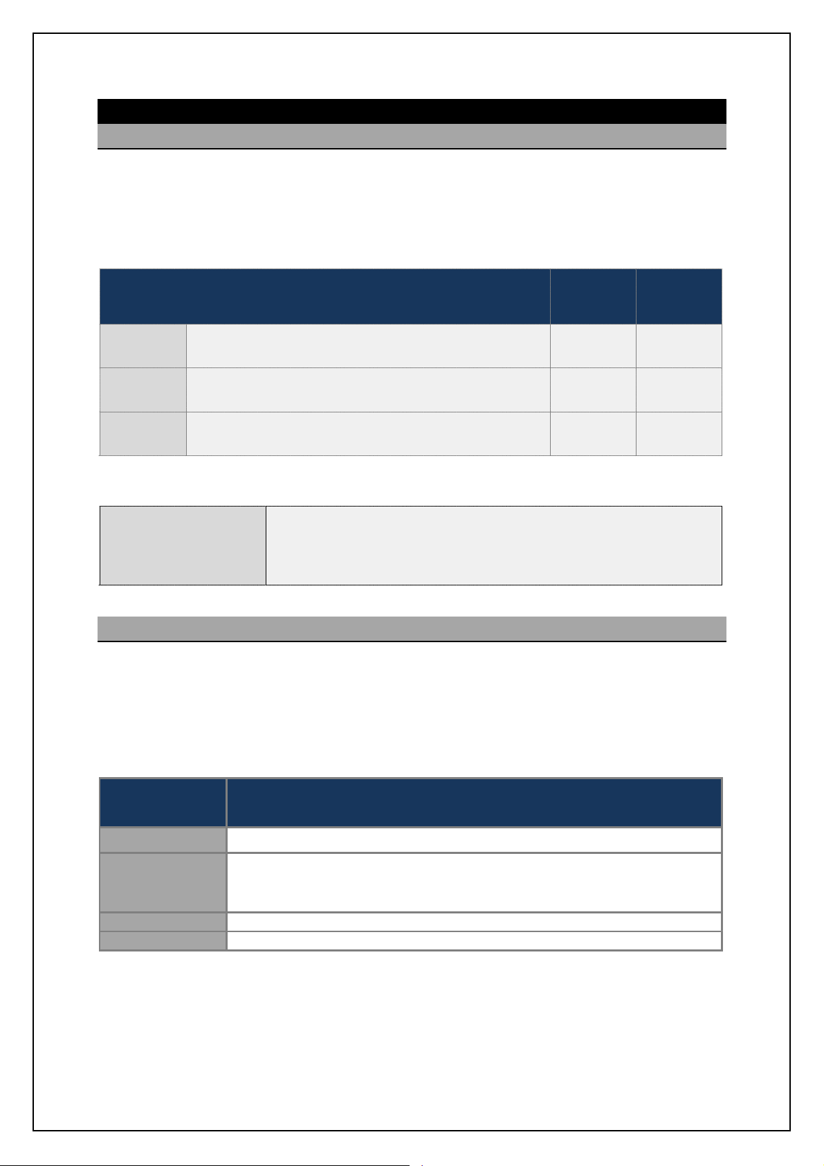
SBS-900Shore Based Radar Systems
(No radar input cardfitted)
Chapter 8: Service display/ RadarView control
8 Service display/ RadarView control
8.1 Overview
SBS systems can be controlled and radar returns viewed using the optional range of service displays.
Service displays can be used as a maintenance/ commissioning tool or when correctlyconfigured, as
a primary means of system control.
There are a number of service display options for the SBS series as follows:
Service display part number & description
SBS-A3-2
SBS-A3-3
SBS-A3-5
Single radar sensor
Base components for integrationinto a 3rdparty supplied PC
Single radar sensor display
RS232/ ASTERIX control & monitoring
Single radar sensor
LAN/ ASTERIX and RS232 control & monitoring
SBS-900-1
SBS-900-2
SBS-900-51
& &
& &
%
SBS-900-3
SBS-900-4
&
LAN kit required.
See Note
All service displaysare supplied with the following software pre-loaded.
RadarView Software: This software provides the radar processing and display
ZM-2283
RadarView software
and has integrated control and monitoringfunctionsfor the SBS series.
Operator instructions:The use and operator instructions for the ZM-2283
RadarView and SBScontrol software can be found in Annex B.
8.2 SBS-A3-2 Base system
The SBS-A3-2 allows the serial control of a single transceiver system via a customersupplied third
party PC/ Microprocessor. See the options section in the system overview handbook for the minimum
PC specification.
The kit provides all the hardware and software to be installed onto a PC to make the system
compatible with the SBS series and comprises the following:
Kelvin Hughes
part number
Description
SBS-A109 08 l[]e giohn[\f_ '0T( mervice display patch panel and cables
RadarView software including SBS radar control and replay software for
ZM-2283
maintenance displays.
Supports of HPx-200 and/ or Asterix video.
45-980-0041-001 HPx-200 PCI radar interfacecard
ZM-2602 SBS service display graphic V2
Note: The SBS-A3-5 service displaycan only be used with the LAN kit is fitted.
KH-1602-2 issue 1: Standard SBS900 Systems Operator & Maintenance Handbook
Page 73 of 240
Page 74

SBS-900Shore Based Radar Systems
number
number
Supports of HPx
-
200 and/ or Asterix video.
Note:
Other
cable
lengths are available;pleasecontact Kelvin Hughesfor
additional details.
Chapter 8: Service display/ RadarView control
8.3 SBS-A3-3 Single transceiver
The SBS-A3-2 ecn ]ihn[chm [ 08 l[]e giohn[\f_ '1T( gc]lijli]_mmil jl_fi[^_^ qcnb [ff nb_
necessarysoftware and an interface place for connecting the system to a single transceiver system.
Single transceiver
SBS system
Kelvin Hughes part
Video/ Sync (analogue)
Serial control
Description
SBS-A3-3
Service display
45-975-0183-001 08 '2U) rack mountable microprocessor.
SBS-A109 08 l[]e giohn[\f_ '0T( mervice display patch panel and cables
RadarViewsoftware including SBS radar control and replay software for
ZM-2283
maintenance displays.
Supports of HPx-200 and/ or Asterix video.
45-980-0041-001 HPx-200 PCI radar interfacecard (preinstalled into the PC)
ZM-2602 SBS service display graphics card (preinstalled into the PC)
SBS-A124-11
Cable kit for connecting the SBS-A109 plate to the SBS system (11m)
Note: Other cablelengths are available; please contactKelvinHughes for additional details.
8.4 SBS-A3-4 dual transceiver
The SBS-A3-3 ecn ]ihn[chm [ 08 l[]e giohn[\f_ '1T( gc]lijli]_mmil jl_fi[^_^ qcnb [ff nb_
necessarysoftware and two interface places for connecting to a dual transceiver system.
Dual transceiver
SBS system
Kelvin Hughes part
2 x Video/ Sync (analogue)
2 x Serial control
Description
SBS-A3-3
Service display
45-975-0183-001 08 '2U) rack mountable microprocessor.
SBS-A109 1 r 08 l[]e mountable (1U) service display patch panel and cables
RadarViewsoftware including SBS radar control and replay software for
ZM-2283
maintenance displays.
45-980-0041-001 2 x HPx-200 PCI radar interface card (preinstalledinto the PC)
ZM-2602 SBS service display graphics card (preinstalled into the PC)
SBS-A124-11
KH-1602-2 issue 1: Standard SBS900 Systems Operator & Maintenance Handbook
Cable kit for connecting the SBS-A109 plate to the SBS system (11m)
Page 74 of 240
Page 75

SBS-900Shore Based Radar Systems
Supports of HPx
-
200 and/ or Asterix video.
Note
2
Or LAN control
Chapter 8: Service display/ RadarView control
8.5 SBS-A3-5 ASTERIX control
The SBS-A3-4 ecn ]ihn[chm [ 08 l[]e giohn[\f_ '1T( gc]lijli]_mmil jl_fi[^_^ qcnb [ff nb_
necessarysoftware for connection to a dual transceiver system.
The service display can accept ASTERIX video and control is possible via Serial or LAN connection.
Note
Dual transceiver
SBS system
2 x Serial control
Note 1
SBS-A3-3
Service display
Kit contents
The SBS-A3-4 dual radar service kitcomprises of the following:
45-975-0183-001 08 '2U) rack mountable microprocessor.
ZM-2283 RadarView software including SBS radar control and replay softwarefor
maintenance displays.
ZM-2602 SBS service display graphics card (preinstalled into the PC)
SBS-A220-11 Cable kit for connecting the SBS-A109 plate to the SBS system (11m)
8.6 Keyboard, monitor & Mouse
The processor requires a flat screen display, standard USB QWERTY keyboard and USB mouse (not
supplied). If these are required the following commercial off the shelf products can be supplied:
Kelvin Hughes part
number
Description
Monitor
45-975-0189-001
Keyboard
45-975-0191-001
Mouse
45-975-0190-001
Note 1: LAN control is only availablewhen the LANinterface kit has been fitted to the Radar DistributionUnit (kit reference
SBS-A129).
Note 2: Othercable lengths are available; please contact Kelvin Hughes for additional details.
22 inch wide screen LCD monitor.
Auto-ranging AC input 110VAC to 230VAC47Hz to 63Hz.
Case colour black.
USB QWERTY keyboard, case/ key colour black.
Black USB optical scrollmouse with three buttons.
KH-1602-2 issue 1: Standard SBS900 Systems Operator & Maintenance Handbook
Page 75 of 240
Page 76

SBS-900Shore Based Radar Systems
DVD open/ close button
2 x USB port
Chapter 8: Service display/ RadarView control
8.7 Service Display PC overview
Sb_ `iffiqcha acp_m [h ip_lpc_q i` nb_ 08 '1T( l[]e giohn_^ gc]lijli]_mmil om_^ ch nb_
SBS-A3-3, -4 & -5 service displays.
Note: The make and model of the service display PC may change from the version shownhowever the switch functionality
and input/ output connectivitywill be similar.
VGA/ HDMI /
AVI outputs
COM1
connection)
(Serial
SBS-A3-3 Service display front view
LAN input
Mains input
and Power
switch
Air filter
Power & Hard drive LED
Reset switch
Power switch
Detail of service display controls
SBS-9.-67 .6q eTV^ `bhagTU_X %.M& fXei\VX W\fc_Tl \agXeYTVX c_TgX7
The following plate is used to connect signals to the service display (1 plate required per transceiver).
The system runs thesoftware required to display and control a single radar sensor but does not
include a monitor, keyboard or mouse.
KH-1602-2 issue 1: Standard SBS900 Systems Operator & Maintenance Handbook
Page 76 of 240
Page 77

SBS-900Shore Based Radar Systems
Chapter 8: Service display/ RadarView control
8.8 Switching ON/ OFF
SBS-A3-2: Third party system
The operation of third party PC equipment used in the SBS-A3-2 service display is not detailed within
this handbook. Please refer to the user manuals supplied with the original third party equipment.
SBS-A3-X: 2U 19 inch processor rack
The following details the switching ON/ OFF of the microprocessor used in the SBS-A3-3, -4
& -5.
i. Ensure an AC mains supply is connected to the system and is switched
ON (115/ 230VAC auto-ranging)
SwitchON
Run RadarView
application
ii. Open the front panel of the service display processor.
iii. Place the power switch into the ON ( I ) position.
iv. The green power LED illuminates and the processor will start.
When the service display has started, run the RadarView
application from the desktop.
A brief overview of the operation of RadarView software
can be found in the following section.
RadarView desktop icon
Reset
Closing the
RadarView
application
Shut-down and
switch OFF
If a system lockup or freeze occurs, temporarily press the Reset switch which
restarts the processor.
Caution:Pressing reset aborts all programs that are running. All unsaved workand
temporaryconfigurations will be lost. The main system configurations and settings are
retained.
Prior to switching the OFF service display, the RadarView application must be
closed.
Ensuringthe RadarView application has closed,shut down the system using
the Start/ shutdown function from the Windows desktop.
WhenWindows has shut-down, place the power switch into the OFF (0)
position or if theswitch is spring loaded, press and hold the OFF button for 5
seconds)
KH-1602-2 issue 1: Standard SBS900 Systems Operator & Maintenance Handbook
Page 77 of 240
Page 78

SBS
900 ShoreBased
Radar Systems
Chapter
Service display/ RadarView control
KH
:
Page
78
of
8.9
Emergency Stop
The Emergency Stop is a function within the RadarView software that isolates power to the
transceiver
enclosure
and antenna turning
service display
is
If the Service display is
the Emergency Stop
function
cannot be accessed/ used.
Emergency Stop is designed to be used by the operator if an emergency situation is detected that
requires immediate sh
The software Emergency Stop function must neverbe used to stop the system for
maintenance purposes or for working aloft.
The system must be fully isolated from all sources of power prior to carrying out any maintenance
task or before working aloft.
To activate the EmergencyStop function, select
then
from the
RadarViewmain screen.
Press the
Yes
Antenna rotation and
system transmission is
stopped.
NO
Action cancelled.
The system continues to
operate normally.
When the Emergency Stop is activated, the following system changes occur:
Antenna
Stop
is automatically selected.
AC power:
Single & three phase relays (R1, R2
and CON1) switch OFF.
Standby
Alarm:
An
alarm is
generated
at the RDU.
The
button text
changes to
Restart.
Antenna
AC power is removed
from the Antenna
Sub
Antenna rotation is stopped.
AC power is removed from the
transceiver
Enclosure.
System transmission is stopped.
line
% 1=175) 14 1AJ
Emergency stop button and the following occurs:
Emergency Stop
Emergency Stop
System.
1602 2
Standard SBS900 Systems Operator & Maintenance Handbook
Page 79

SBS
900 ShoreBased
Radar Systems
Chapter
Service display/ RadarView control
KH
:
Page
79
of
Emergency Stop
system re
start
When the situationthat caused the Emergency Stop function to be activated has been cleared, the
system must be restarted:
Pressing the
Restart
Further operator action is required from the RadarView software to then commence system
transmission and antenna rotation:
Yes
The RDU is availableto
restart transmission
NO
Action cancelled.
Antenna Speed:
Select the
required antenna speed
TransceiverMode:
Switch from
Standby
RUN
to commence transmission.
The system will now operate normally.
button is pressed configures the RDU so that it isready to go to RUN.
1602 2
Standard SBS900 Systems Operator & Maintenance Handbook
Page 80
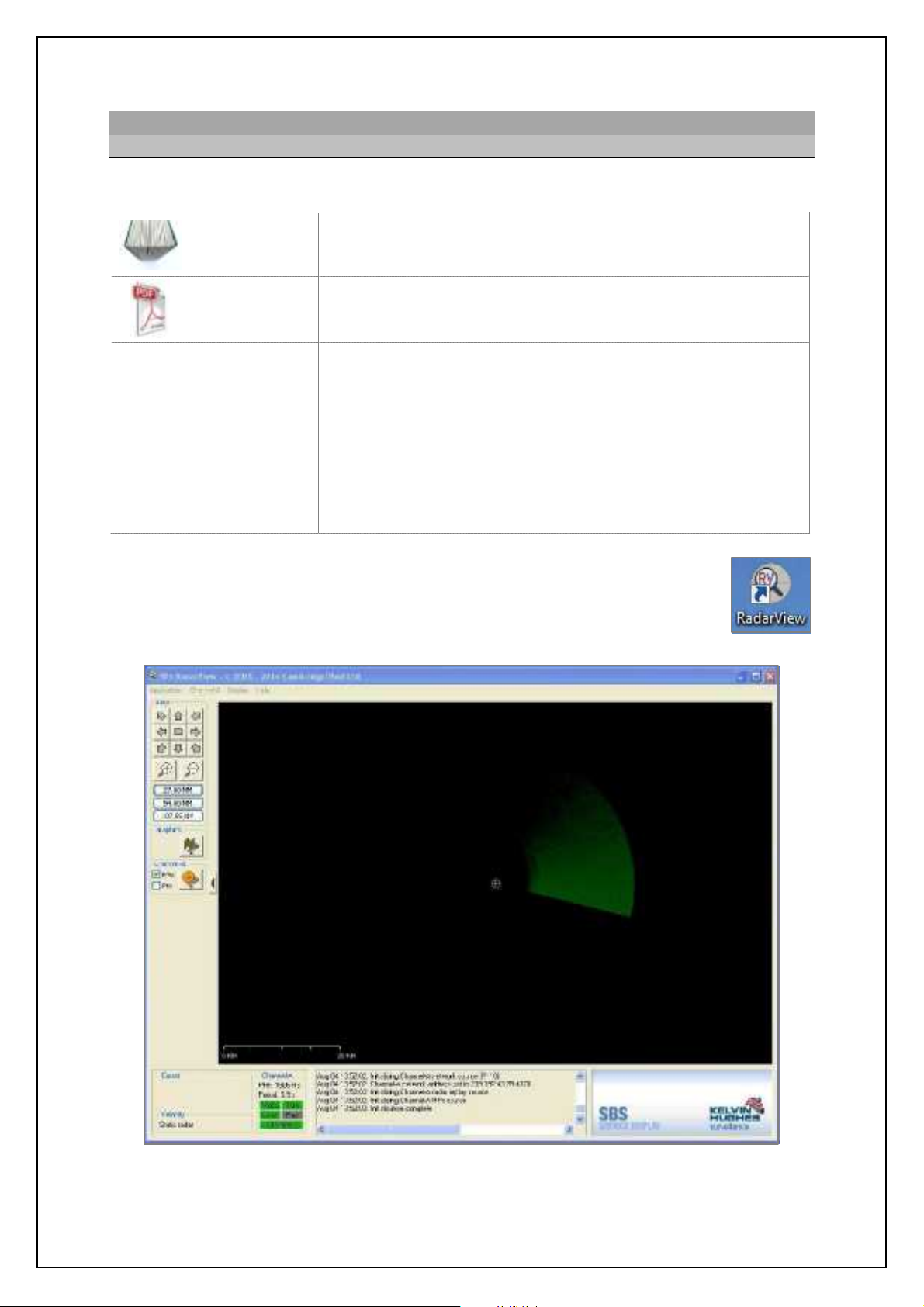
SBS-900Shore Based Radar Systems
Chapter 8: Service display/ RadarView control
8.10 RadarView operator overview
8.10.1Overview
The manufactures operator handbook for RadarView can be located as follows:
Printed copies
Electronic
copies(PDF)
In printed copies of this handbook, a copy of the RadarView user
manual can be found in section Annex B.
In electronic copies, the RadarView user manual can be found in the
root directory of the KH1600 document (PDF format).
SPx RadarView for WindowsUser Manual
Documentnumber: CP-25-110-27
Documentdetails and
copyright notice:
CambridgePixel
RadarView
user manual
Kelvin Hughes Ltd is not responsible for the content of the
RadarView user manual which remains the copyright of Cambridge
Pixel Ltd.
Document reference CP-25-110-27 contains proprietary information that is
sensitive to the commercial interests of Cambridge Pixel Ltd. The contents
of this document should not be communicated to third parties without the
prior written consent of the Company.
The following i``_lm [ \lc_` ip_lpc_q i` nb_ Q[^[lUc_q ij_l[nilm m]l__h. Users must
refer to the manufactureshandbook noted above for full instructions.
The RadarView application is run by double clicking on the desktop icon; this will
open the main PPI view shownbelow.
Example of RadarView screen for an SBS-900-2 system
KH-1602-2 issue 1: Standard SBS900 Systems Operator & Maintenance Handbook
Page 80 of 240
Page 81
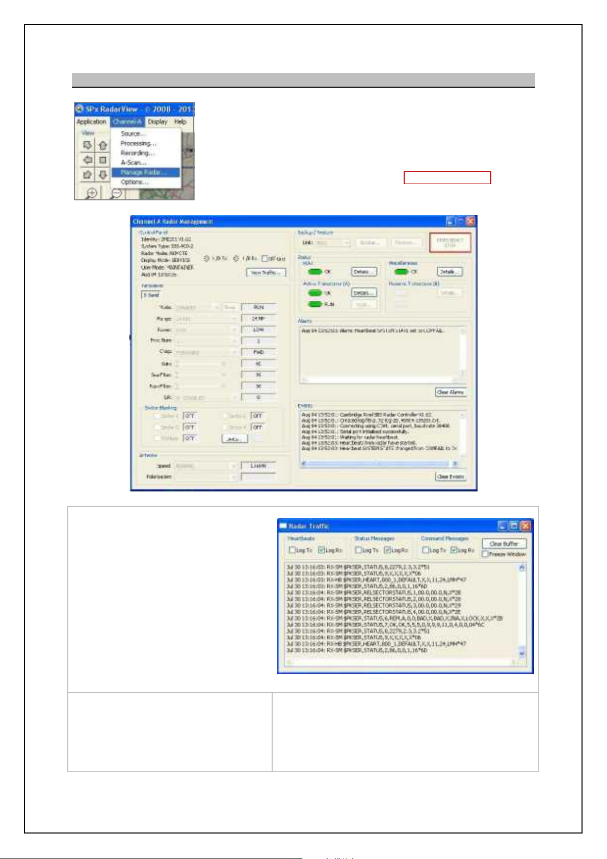
SBS-900Shore Based Radar Systems
Each section is detailed on the following pages.
Chapter 8: Service display/ RadarView control
8.10.2 RadarView p manage radar
Selecting •Channel-9 , ETaTZX JTWTeor opens the Manage Radar
screen which allows the remote control and viewingof:
- The Radar Distribution Unit (RDU).
- Transceivers.
- System information.
The screen also allows the activation of the Emergency Stop function.
Control Panel
- View system information (software
versionetc.).
- H/B: Shows the transmitted and
received Heartbeats (flashes green).
- Off-line: Select to take the service
display Off-line.
- N\Xj LeTYY\Vo: Opens a new window
showing the messages flowing
between the service display and the
RDU.
Transceiver
Shows the current transceiver settings.
Antenna
Shows the current antenna speed.
KH-1602-2 issue 1: Standard SBS900 Systems Operator & Maintenance Handbook
View Traffic window
Sector Blanking
Shows the status of blanking sectors & Mute ON/ OFF.
Tune
Shows the current tune level
Page 81 of 240
Page 82
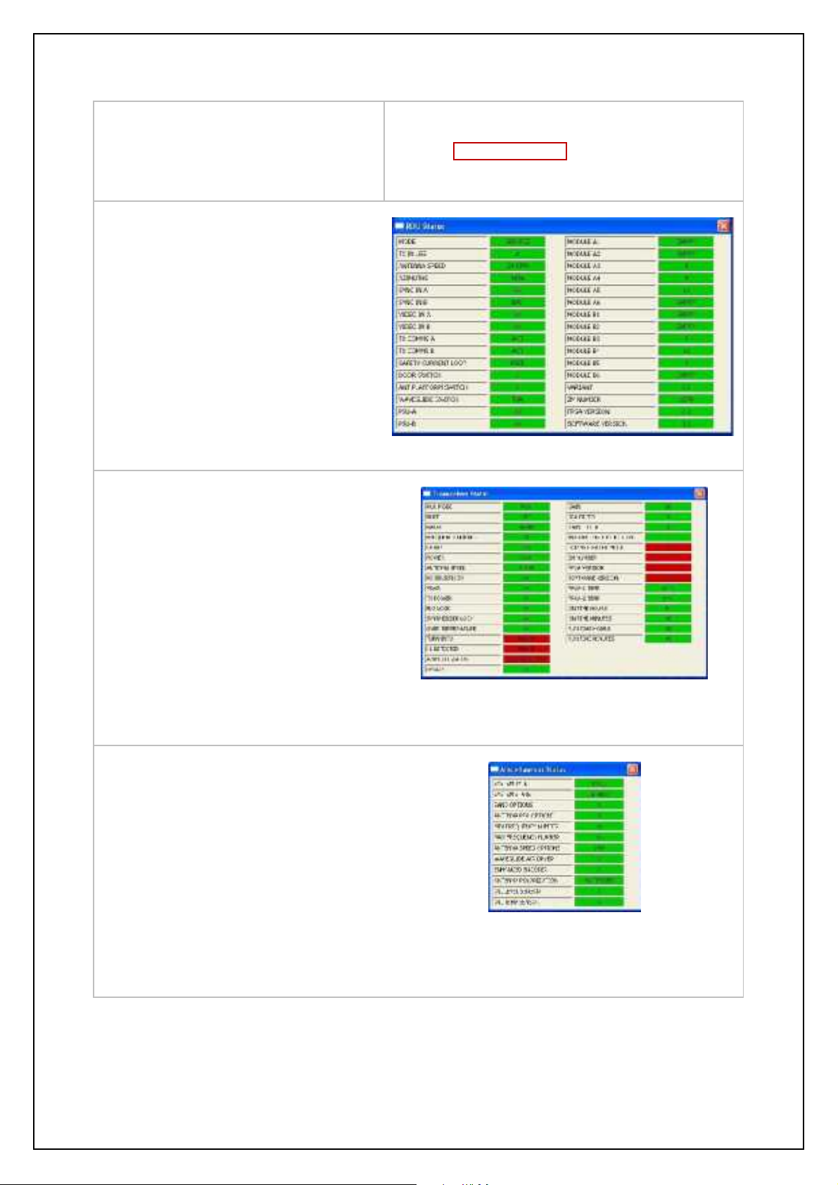
SBS-900Shore Based Radar Systems
Chapter 8: Service display/ RadarView control
Backup & Restore
Backup or restore the RadarView settings.
Status p RDU
Select the 8Q_MUW^f button for information.
Status Green: No fault conditions exist.
Status Red: A fault condition is present.
Status p Active or Reserve Transceiver
Select the 8Q_MUW^f button for information.
Emergency Stop
Selecting Emergency Stop sends an antenna/
trasnmissionstop command to the RDU. All AC power
is removed from the transceiver/ gearbox.
RDU rDetailsps
Status Green: No fault conditions exist.
Status Red: A fault condition is present.
Status p Miscellaneous
Select the 8Q_MUW^f button for information.
Status Green: No fault conditions exist.
Status Red: A fault condition is present.
Example of the Active Transceiverwindow
Example of Miscellaneousstatus
KH-1602-2 issue 1: Standard SBS900 Systems Operator & Maintenance Handbook
Page 82 of 240
Page 83

SBS
Radar Systems
Chapter
Service display/ RadarView control
KH
:
Page
83
of
8.10.3
Transceiverwarm up:
At switch ON, the transceiver enters a
transceiver(s) will show as
Not Ready
as Red.
After the
initialisation period
is ready for use.
Magnetron heater
The system is shipped with themagnetron heaters configured to be
always ON, i.e. when the system is
swi
and in
state indefinitely.
During commissioning it is possible to set the magnetron heaters to switch OFF when set to Standby
after a pre
Ready and the 90
second delay would be required before the unit becomes available for use.
Heater
turn
down/ Standby OFF delay may be a site requirement to preserve the life of the
magnetron.
Caution:
The RadarView software DOES NOT report when the heaters have switched
OFF and will continue to show the transceiver as Ready (green).
If the
delay whilst the transceiver warms up.
View heater time:
To view the heater turn
down time, select the following menus on the LCD display
of the transceiver(s):
Defaults / Heater / SBY OFF delay:
Ready
No
t Re
down
900 ShoreBased
short initialisation period
Standby
Ready
ady
system is swapped to a transceiver that has been switched OFF, there will be a 90second
1602 2
Standard SBS900 Systems Operator & Maintenance Handbook
Page 84

SBS-900Shore Based Radar Systems
Chapter 8: Service display/ RadarView control
Page intentionally blank
KH-1602-2 issue 1: Standard SBS900 Systems Operator & Maintenance Handbook
Page 84 of 240
Page 85

SBS-900Shore Based Radar Systems
Chapter 9: Planned maintenance
9 Planned maintenance
9.1 Standard Antenna Systems
Equipment: The following pages detail the monthly, annual, 3 and 5-year planned
maintenance schedules for thefollowing Standard antenna sub-systems.
LPA-A37
LPA-A55
LPA-A3
LPA-A455
DTX-A3
GTX-A11
DTX-A19
DTX-A7 Downmast transceiverenclosure (all variants)
SBS-A1 RDU - Radar Distribution Unit (all variants)
55-100-0436-001 Static desiccator
Recommended maintenance schedule:
X and S-band Low Profile Antennas (all variants)
X and S-band gearboxes (all variants)
( General inspection and cleaning of the system
Annual:
3-year: ( Replacement of gearbox oil
5-year: ( Replacement of static inverter and RDU power supply fans
Maintenance record: The following pages have been designed to be printed, completed and stored
Procedure: Prior to carrying out any maintenance the system must be fully isolated from
Spares: Where required, only Kelvin Hughes approved spares must be used. The use
( Fan checks
( Safety checks
as a maintenance record for standard systems.
Any damage that is identified as partof an inspection should immediately be
reported to Kelvin Hughes and appropriate action taken to prevent further
damage occurring.
all sources of AC power including any UPS supported supplies, the required
maintenance task(s) should be undertaken and on completion, the power
restored and the system fully tested.
of unapproved spares invalidates the warranty status of the unit could lead to
a malfunction of the system.
Adverse weather: It is strongly recommended that the gearbox inspections noted in Annual
Maintenance procedures are carried out at the earliest safe opportunity after
the system has been exposed to severe or adverse weather conditions.
Health & safety: All safety warnings for the system noted in section 2 must be observed at all
times when working on, inspecting or maintaining any part of the system or
its associated sub systems.
KH-1602-2 issue 1: Standard SBS900 Systems Operator & Maintenance Handbook
Page 85 of 240
Page 86

SBS-900Shore Based Radar Systems
Chapter 9: Planned maintenance
9.2 Advanced Antenna Systems
The planned maintenance proceduresfor the
Advanced ST1-F10/ 20 Antenna Turning Unit
(ATU) and antenna range are briefly outlined
below but are notdetailed in this handbook.
ST1-F10/ 20 Antenna TurningUnit& antenna
Please refer to the installation and maintenance handbook supplied with the advanced
equipment for full details on planned maintenance.
Electronic copies of these handbooks (Pdf) are available on request.
For reference use only, the recommended maintenance schedule is:
Recommended maintenance schedule for ATU and antenna:
Every 6 months:
Every 6 years:
( General inspection of theATU and the antenna.
( Replacement of the crossed roller bearing of the bearing-mounted
antenna mountingflange.
( Replacement of the gearbox complete with motor
( Replacement of the rotary joint.
Transceiver enclosure and Radar Distribution Unit:
The transceiver enclosure and Radar Distribution Unit MUST be inspected in line with the
Standard system planned maintenance schedule which is shown in the following section.
This includes the inspection of the following equipment:
DTX-A7 Downmast transceiverenclosure (all variants)
SBS-A1 RDU - Radar Distribution Unit (all variants)
55-100-0436-001 Static desiccator
WARNING:
Lethal voltages are present within the equipment.
All maintenance procedures must be carried out with all relevant power sources switched
OFF, fully isolated anddisconnected.
Health & Safety precautions: All health & safety notices noted in this document and theenhanced
system handbook must be read and observed at all times.
KH-1602-2 issue 1: Standard SBS900 Systems Operator & Maintenance Handbook
Page 86 of 240
Page 87

SBS-900Shore Based Radar Systems
Chapter 9: Planned maintenance
9.3 System isolation
In addition to the normal healthand safety requirements, the system must be made safe prior to
carrying out any maintenance task by fully isolating all AC power including any UPS supported
supplies to the system as shown below:
Man aloft
switch
(MAS)
RDU
Antenna
rotation
switch
DTX-A7
Transceiver
enclosure
RDU
AC power
As an additional safety precaution, the Man Aloft Switch
can be placed into the OFF position.
This acts as a backup safety measure to removing the
Antenna Rotation keyswitch.
Place the Antenna Rotation keyswitch on the front of the
Radar Distribution Unit into the OFF position.
The key should be removed and retained until the
maintenance task being undertakenhas been completed.
Ensure that the AC breaker(s) located within the
transceiverenclosure are in the OFF position.
Note: Sb_ KDCm ih _[]b \l_[e_l [l_ cffogc[n_^ qb_h @B
supplies are still connected to the transceiver enclosure.
Within the Radar Distribution Unit, ensure all
breakers are inthe OFF position.
Note: Vb_h mqcn]b_^ NEE+ nb_ KDCm ih _[]b
breaker remain illumiated indicating that AC
supplies are still connected to the RDU.
External AC
Isolate and disconect ALL single and 3-phase AC supplies to the Radar
Distribution Unit including all UPS supported supplies and physically remove all
power sockets.
The system is now fully isolated from all sources of AC supply.
KH-1602-2 issue 1: Standard SBS900 Systems Operator & Maintenance Handbook
Page 87 of 240
Page 88

SBS-900Shore Based Radar Systems
Note
number(s)
date:
Chapter 9: Planned maintenance
9.4 Annual maintenance procedure
SBS-900 Annual planned maintenance record sheet
Equipment details
Antenna Sub-System
Gearbox/ Antenna Turning Unit Antenna
Part No.
Serial
number:
Transceiver enclosure
Part number DTX-A7-
Serial
Radar Distribution Unit (RDU)
Part number SBS-A1-
Serial
number(s)
Man Aloft Switch (MAS)
Part number SBS-A132
Part
No.
Serial
No.
Inspection sheet
1 of 10
Serial
number
Inspection
Inspected by:
Print: Sign:
(DD/ MM/ YYYY)
' Bloweror soft brush.
' Medium flat head screwdriver (for opening RDU and transceiver enclosure).
' Mild detergent
Tools
required
Note: Do not use abrasive cleaners or products containing alcohol.
' Soft abrasive free cloth.
' Safety ohmmeter, bridge Megger or Multimeter.
' Spanners (6mm, 10mm and as required for custom earth attachments).
' Wire brush or emerycloth.
Skill level Basic electricaltraining, working at heights awareness.
Time Approximately three hours depending on equipment locationand accessibility
Note - Advanced ATU and antennas: Please referto the advanced installation and maintenance
handbook supplied with the equipment for full details on planned
maintenance of advanced equipment.
The maintenance procedure for the Advanced antenna sub-system
is NOTcovered or recorded in this document.
KH-1602-2 issue 1: Standard SBS900 Systems Operator & Maintenance Handbook
Page 88 of 240
Page 89

SBS-900Shore Based Radar Systems
Chapter 9: Planned maintenance
SBS-900 Annual planned maintenance record sheet
WARNING: Prior to commencingany maintenance procedure, users must familiarise themselves
with the health & safety warnings noted in the planned maintenance and health and safety sections
of the system handbooks.
Prior to carrying out plannedmaintenance, the system must be fully isolated from ALL single and 3phase AC supplies including any UPS supported supplies.
Caution: When the gearboxand antenna have been operating in strong sunlight or elevated
temperatures, the gearbox casing and antenna surfaces will be extremely hot.
Inspection sheet
2 of 10
Antenna inspection
Task Description Pass Fail
Clean the antenna facia with a soft clothmoistened in a mild nonabrasive soap solution.
Cleaning
Note1: Cleaning the antenna is important as the system performance can be
degraded if the antenna transmission face becomes obscured by dirt.
Note2: The antenna facia must never be painted.
Ensure that all securing bolts are tights, secure and showno signs of
severe corrosion or damage.
' '
' '
Physical
inspection
Check that waveguide couplings are securely fastened and appear to
be waterproof.
' '
The antenna should be checked to ensure that there is no obvious
external damage, cracking or potential faults that could lead to a
' '
general failure of any part of the system.
Check the antenna for signs of excessive vertical end play.
' '
Example of antenna end-play
If the end play is more than +/-10mm please consult with Kelvin
Hughes.
Caution:
' The followingtests should only be undertaken when it is safe to manually rotate the antenna
i.e. the system is fully isolated from all sources of power and the antenna can be safely
accessed and reached.
' Do not use excessive force.
' Do not take unnecessary risk when turning the antenna such as reaching too far or leaning
outside safety guardrails.
' This task should be disregarded if there are any safety concerns.
Task Description Pass Fail
Manual
antenna
rotation
Noting the above safety precautions and where safe to do so,
manually rotate the antenna and ensure that it is free from obstruction
and turns smoothly
KH-1602-2 issue 1: Standard SBS900 Systems Operator & Maintenance Handbook
' '
Antenna
not
accessible
Page 89 of 240
'
Page 90

SBS-900Shore Based Radar Systems
Chapter 9: Planned maintenance
SBS-900 Annual planned maintenance record sheet
Inspection sheet
3 of 10
Gearbox inspection
Task Description Pass Fail
General
cleaning
Clean all exterior surfaces with a soft, cloth moistened in a mild nonabrasive soap solution.
' '
Ensure that all securing bolts for the gearbox and antenna are secure
and show no signs of severe corrosion or damage. Pay particular
attention to the bolts that hold the gearbox assembly onto the
' '
mounting plate.
Inspect the gearbox including all mounting points for any signs of
stress damage.
Severe weather: This inspection should be carried out at the earliest
' '
safe opportunity after the system has been exposed to severe or
Physical
inspection
adverse weather conditions.
Check that cable glands, cable entries and waveguide couplings are
securely fastened and appear to be waterproof.
' '
Within reason and wheresafe to do so, check all accessible or
exposed cablesfor any signs of damage and ensure they are safely
' '
secured into/ onto cable trays or trunking.
Earth
bonding
and
continuity
The system should be checked to ensure that there is no obvious
external damage or potential fault conditions that could lead to a
general failure of any part of the system.
Check for any signs of oil leaks from the gearbox assembly.
Ensure that the earth bonding nuts and bolts are tight and free from
corrosion.
If corrosion is present, clean and re-terminate as described in section
9.7 page 114.
Test the earth bonding conductivity by attaching one lead of the test
equipment
note1
to earth/ chassis and the other to an unpainted part of
the equipment under test.
Check earth bonding for continuity, the resistance should not exceed
0.1 ohms. If a test fails, investigate the bonding, rectify (see section
9.7 page 114) and repeat the test.
Note1: Safety ohmmeter, bridge Meggeror Multimeter.
' '
' '
' '
' '
KH-1602-2 issue 1: Standard SBS900 Systems Operator & Maintenance Handbook
Page 90 of 240
Page 91

SBS-900Shore Based Radar Systems
and
/ or
soft brush.
Chapter 9: Planned maintenance
SBS-900 Annual planned maintenance record sheet
Inspection sheet
4 of 10
Radar Distribution unit (RDU)
Task Description Pass Fail
External
surfaces
Cleaning
Internal
surfaces
Clean with a soft, non-abrasive cloth moistened in a mild
soap solution.
Open the door of the Radar Distribution Unit using a
screwdriver. Carefully clean out the unit using blower
' '
' '
Ensure that all mounting bolts are secure. ' '
External
Ensure all connectors are securelyin place; inspect
internal cabling for condition and wear.
Check that all air vents are clear of obstructionsand
dust.
' '
' '
Physical
inspection
Dhmol_ [ff OBAm [h^ ]ihh_]nilm [l_ m_]ol_fs ch jf[]_;
inspect internal cabling for condition and wear.
' '
Internal
Check that all air vents and fans are clear of obstructions
and clear of dust accumulation.
' '
Earth
bonding
and
continuity
The system should be checked to ensure that there is no
General
obvious internal, external damage or potential fault
conditions that could lead to a general failure of any part
of the system.
On the underside of the RDU, visually inspect the earth terminal for
damage and corrosion.
If corrosion is present, clean and re-terminate as described in section
9.7 page 114.
Check that the earth bonding strap between the RDU door and
chassis is present, clean and re-terminate as described in section 9.7
page 114.
Test the earth bonding conductivity by attaching one lead of the test
equipment
note1
to earth/ chassis and the other to an unpainted part of
the equipment under test.
Check the earth bonding for continuity, the resistance should not
exceed 0.1 ohms. If a test fails, investigate the bonding, rectify and
repeat the test.
Note1: Safety ohmmeter, bridge Meggeror Multimeter.
' '
' '
' '
' '
KH-1602-2 issue 1: Standard SBS900 Systems Operator & Maintenance Handbook
Page 91 of 240
Page 92

SBS-900Shore Based Radar Systems
Chapter 9: Planned maintenance
SBS-900 Annual planned maintenance record sheet
Inspection sheet
5 of 10
DTX-A7-xx Transceiver enclosure
Task Description Pass Fail
General
cleaning
Clean all exterior surfaces with a soft cloth moistenedin a mild nonabrasive soap solution.
' '
Ensure that all securing bolts are secure and show no signs of severe
corrosion, damage. Pay particular attention to the main chassis
' '
supporting bolts.
Inspect the unit including all mounting points for any signs of stress
damage.
Severe weather: This inspection should be carried out at the earliest
' '
safe opportunity after the system has been exposed to severe or
adverse weather conditions.
Physical
inspection
Check that cable glands, cable entries and waveguide couplings are
securely fastened and appear to be waterproof.
Within reason and wheresafe to do so, check all accessible or
exposed cablesfor any signs of damage and ensure they are safely
' '
' '
secured into/ onto the cable tray or trunking.
Static
Desiccator
The system should be checked to ensure that there is no obvious
external damage or potential fault conditions that could lead to a
' '
general failure of any part of the system.
Check that the four wind turned rotary ventilators mounted on top of
the assembly are free from dust and obstructions and can rotate
' '
freely.
Check that no moisture or water is present within the enclosure. ' '
The sachets in the static Desiccator must be changed every 12
months.
The two sachets are withinthe desiccator which is located on the
base of the enclosure or on earlier units between the two front access
doors.
Used/ removed sachets must be disposed of in accordance with local
disposal regulation.
When the sachets havebeen replaced, ensure that the desiccant
enclosure cap is securelyin position and fully tightened.
Replacement sachet: 55-100-0494-002
Notes
' '
Sachet shelf life: 2-years
Notes:
- The part number noted above is for 1 sachet, two are required.
- Split or tornsachets must not be used.
- Replacements must be from asealedpackage (replacements have a shelf life of 2-
years).
- Two sachets MUST be used.
KH-1602-2 issue 1: Standard SBS900 Systems Operator & Maintenance Handbook
Page 92 of 240
Page 93

SBS-900Shore Based Radar Systems
Chapter 9: Planned maintenance
SBS-900 Annual planned maintenance record sheet
Inspection sheet
6 of 10
Transceiver enclosure
Task Description Pass Fail
The air baffle plates located on the base of the Transceiver Enclosure
should be checked and cleaned as necessary.
Base
plate air
baffle
Base of DTX-A7 Transceiver Enclosure
' '
Each baffle is retained by 4 cross-head screws as indicated above.
The plates should be removed and any dust or
foreign objects removedfrom the plate and the
heatsinks above using a brush or blower.
Earth
bonding
and
continuity
If necessary, the ducted fans on the top of the unit
can also be removed to assist in cleaningthe
heatsink void.
These are retained by two crosshead screws at
either end of the enclosure.
Side view of DTX-A7
Ensure that the earth bonding nuts and bolts are tight and free from
corrosion.
If corrosion is present, clean and re-terminate as described in section
9.7 page 114.
Test the earth bonding conductivity by attaching one lead of the test
equipment
note
to earth/ chassis and the other to an unpainted part of
the equipment under test.
Check earth bonding for continuity, the resistance should not exceed
0.1 ohms. If a test fails, investigate the bonding, rectify (see section
9.7 page 114) and repeat the test.
Note: Safetyohmmeter, bridge Megger or Multimeter.
' '
' '
KH-1602-2 issue 1: Standard SBS900 Systems Operator & Maintenance Handbook
Page 93 of 240
Page 94

SBS-900Shore Based Radar Systems
rotation
Chapter 9: Planned maintenance
SBS-900 Annual planned maintenance record sheet
Inspection sheet
7 of 10
Man aloft switch
Task Description Pass Fail
Physical
inspection
Switch
action
Earth
bonding
and
continuity
Ensure that all fastenings are secure and show no signs of severe
corrosion or damage.
Ensure the switch operation is smooth and that both the Free and
OFF positions can be selected.
Test the earth bonding conductivity by attaching one lead of the test
equipment
note1
to chassis/ earth and the other to an unpainted part of
the equipment under test.
Check the earth bonding for continuity, resistance should not exceed
0.1 ohms. If test fails, investigate the bonding, rectify and repeat the
test.
Note1: Safety ohmmeter, bridge Meggeror Multimeter.
' '
' '
' '
55-100-0436-001 Static desiccator
Task Description Pass Fail
The clear wall of the static desiccator unit allows visual
inspection of the desiccant condition.
As moisture is adsorbed the desiccant colour will change
to either:
Deep blue (dry) to pink/white (wet).
or
Physical
inspection
Orange (dry) to purple (wet).
When 80% of the desiccant materialhas changed
' '
colour, the unit should be replaced.
To prevent moisture from entering the breather hole, the
ohcn gomn \_ l_jf[]_^ [m mbiqh qcnb nb_ •hih-`cnncha _h^
that contains the breather hole pointing downwards.
Maintenance frequencynote: In areas of high humidity it may be
necessarytoincreasethe inspectionperiod of the desiccant.
Static
Desiccator
Restore power to the system
On completion of the above maintenance tasks and noting that the following will cause antenna
rotation and system transmission, restore power to the system.
Security
switches
AC
Breakers
Remote
control
Place the Antenna rotation and man aloft switches in the FREE
positions.
Switch the single and three-phase breakers within the RDU ON.
Caution: This will cause the antenna to rotate
Place the Remote/ Local switch on the RDU to the Local position. '
Antenna
Man aloft
'
'
'
Test Test the system and ensure full functionality. '
KH-1602-2 issue 1: Standard SBS900 Systems Operator & Maintenance Handbook
Page 94 of 240
Page 95
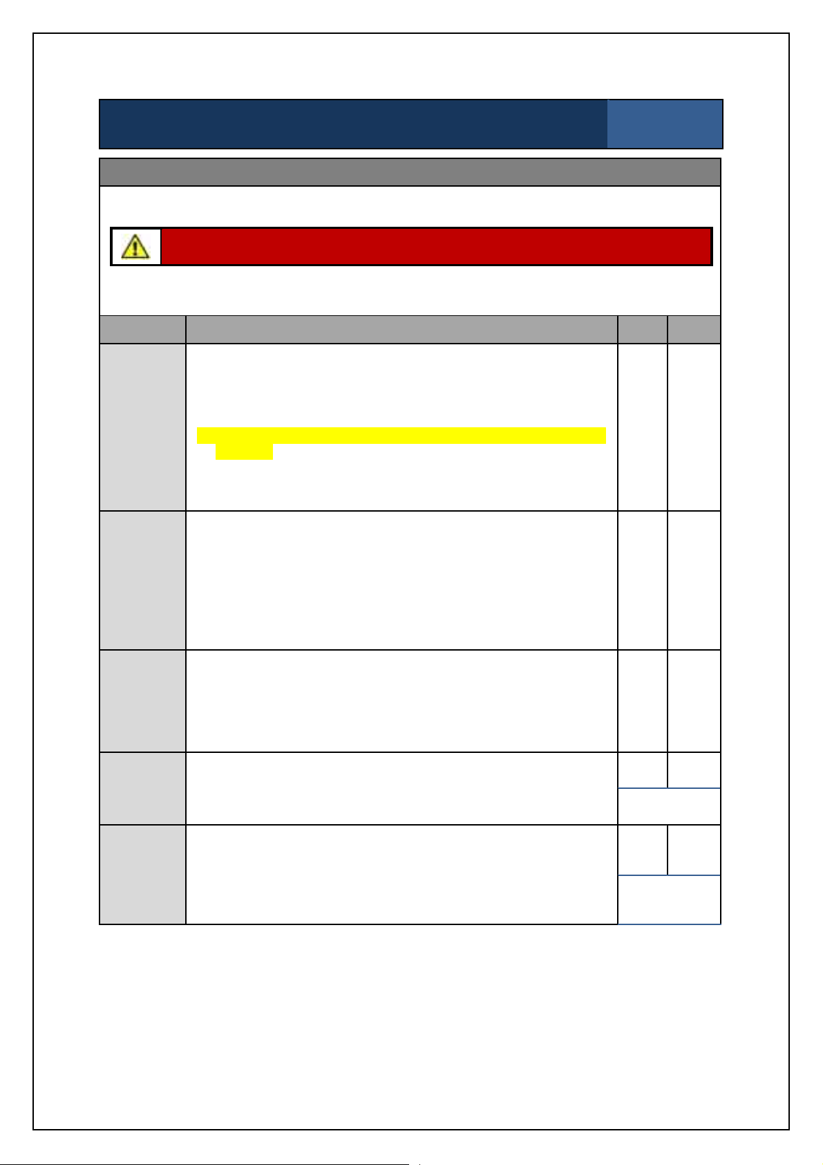
SBS-900Shore Based Radar Systems
Chapter 9: Planned maintenance
SBS-900 Annual planned maintenance record sheet
Inspection sheet
8 of 10
Powered tests: Safety switch tests
The following tests should be carried out with power restored to the system.
Caution: When carryingout the following test, do not contravene any health and safety
precautions regarding working aloft, antenna or electrical safety.
The following tests will Stop and Start antenna rotation and system transmission. The area around
the antenna must be kept clear at all times during these tests.
Task Description Pass Fail
- Set the system to RUN so that it is transmitting and the antenna
is rotating.
- Place the AntennaRotation keyswitch (located on the door of
Antenna
Rotation
keyswitch
(RDU)
the Radar Distribution Unit) into the OFF position.
Remove and RETAIN the key.
- The yellow LED on the front panel of the Radar Distribution Unit
will flash.
' '
- Ensure that thesystem has stopped transmitting, that antenna
rotation has stopped and that the appropriate system alarms are
generated.
Man aloft
switch
(MAS)
Man aloft
switch
& Antenna
Rotation
keyswitch
Hut door
switch
Where fitted
Antenna
platform
switch
Where fitted
- Where safe to do so, change the Man Aloft switch to the OFF
position.
- Reinsert the key into the Antenna Rotation Keyswitch andset to
FREE.
- As the Man Aloft Switch is OFF the system should not transmit
and the antenna rotation should not rotate.
- Place the AntennaRotation keyswitch back to the OFF position.
Remove and RETAIN the key.
- Change the Man Aloft switch to the FREE position.
- Reinsert the key into the Antenna Rotation Keyswitch andset to
FREE.
- Ensure system transmission and antenna rotation commence.
- Open the hut door.
- Ensure the appropriate system alarm is generated at the RDU.
- Close the HUT door.
- Where it is possible and SAFE to do so, open the antenna
platform access door.
- Ensure the appropriatesystem alarm is generated at the RDU.
- Close the antenna platform access door.
' '
' '
' '
Notfitted '
' '
Notfitted '
KH-1602-2 issue 1: Standard SBS900 Systems Operator & Maintenance Handbook
Page 95 of 240
Page 96

SBS-900Shore Based Radar Systems
Chapter 9: Planned maintenance
SBS-900 Annual planned maintenance record sheet
Inspection sheet
9 of 10
Powered tests: Cooling fan checks
The following tests require access to the internal electronics within the Radar Distribution Unit and
the transceiver enclosure.
Caution: Lethal AC, DC and high voltages are present within the system. Exercise
extreme caution when carrying out the following checks.
RDU: There are two fans mounted within the RDU on the power supply assembly:
Task Description Pass Fail
Antenna
isolation
RDU
fan
operation
Transceiver
enclosure
Isolate the 3-phase supply to the Radar Distribution Unit. ' '
- Open the door to the RDU.
- Visually confirm that the two fans on the dual redundant power
' '
supplyare running.
Where fitted, ensure that the SBS-A179 powered fan kits are
operational.
' '
Not fitted '
KH-1602-2 issue 1: Standard SBS900 Systems Operator & Maintenance Handbook
Page 96 of 240
Page 97

SBS
Radar Systems
Chapter
Planned maintenance
KH
:
Page
97
of
SBS
900
Annual
planned maintenance
record sheet
Inspection sheet
Fan condition check
The
fan within the static inverter
located within the Radar
Distribution Unit has a service life
of approximately30,000 hours.
The fan run time must be checked
and the fan replaced where
necessary.
ToshibaVF
Radar distribution unit
F
On the static inverter control panel press the
MODE
button twice and ensure that
is
displayed
Pressthe down (
cumulative operating hours will be
displayed.
The run
= 1 hour,
t1.00
Record the run
time and proceed to the
next step
Pressthe down (
single
height
The fan should be changed when the
changes to a double height line:
If any of the first threelines are double height,
thisindicates a potential fault condition within
the inverter which should be replaced.
If the recorded time is
30000
(t300.00)
hours
the fan must be
Inverterdisplay
Fan OK
Change fan
Inverterdisplay
Change inverter
Task
Description
Result
Fan
condition
check
Inverter fan run time
(e.g.t0.50)
Fan inverter OK or Change fan
the C
Fan OK
Change
Change
fan
time
900 ShoreBased
S11 inverter
) button once and the
time will be indicated by
) button again and 4
changed
F
1602 2
Standard SBS900 Systems Operator & Maintenance Handbook
Page 98

9.5 3-year maintenance
SBS-900Shore Based Radar Systems
Chapter 9: Planned maintenance
3-year maintenance:
Changing gearbox oil (Standard systems only)
Kelvin Hughes DTX-A3-xxxx gearbox and antenna
Inspection sheet
1 of 2
After three years of use, the oil in the standard gearbox should be changed:
Advanced Antenna Turning Unit and antenna: Please refer to the installation and maintenance
handbook supplied with the equipment for full details on planned maintenance.
Equipment details
Transceiver/ gearbox
Part number:
DTX-A3-AXZX
DTX-A3-BXZX
GTX-A11
'
GTX-A11-BAAA
'
DTX-A19
'
DTX-A19-BAAA
'
Serial number:
'
'
Oil change
date:
Changed by:
Print: Sign:
(DD/ MM/ YYYY)
' 5mm across flats hexagonal wrench/ Allen key.
' Suitable syringe or equivalent with small pipe attached for reaching into
gearbox.
Tools required
' Suitable container to hold at least 200ml of oil.
' Mineral oil ARAL DEGOL BG320 quantity 200 ml.
Kelvin Hughes Part No. 55-100-0391-001
' Protective gloves.
Skill level Basic electrical and mechanical training, workingat heights awareness.
Time Less than two hoursdepending on equipment location and accessibility
KH-1602-2 issue 1: Standard SBS900 Systems Operator & Maintenance Handbook
Page 98 of 240
Page 99

SBS-900Shore Based Radar Systems
Chapter 9: Planned maintenance
3-year maintenance:
Changing gearbox oil (Standard systems only)
Inspection sheet
2 of 2
Health & safety precautions
WARNING: Prior to commencing any maintenance procedure, users must familiarise
themselves with the health & safety warnings noted in the planned maintenance and
health and safety sections of the system handbooks.
AC power: Prior to carrying out any planned maintenance,the system must be fully
isolated and disconnected from all sources of single and 3-phase supply including any
UPS supported supplies.
Caution: Whenthe transceiver, gearbox and antenna have been operating in strong
sunlight or elevated temperatures, the gearbox casing and antenna surface will be
extremely hot.
Gearbox: Under no circumstancesshould any attempt be made to remove the motor from the
gearbox or the gearbox from the main chassis as this will lead to major loss of oil and damage to
the sealing gaskets.
Gloves: Protective gloves must be worn at all times when the changing oil in the gearbox.
CoSHH: Please refer to the CoSHH (Control of Substances Hazardous to Health) sheet
supplied with the oil for information on the oil including hazard identification, first aid,
fire precautions and disposal recommendations.
Temperature: Due to the pour point of the oil, this task should not be carried out when the ambient
temperature is below -15 deg C.
Oil: When the gearbox has been operating in elevated temperatures, the oil removed
from the gearbox may be hot.
Disposal: Oil removed from the gearbox must be disposed of in accordance with local waste
disposal regulations.
Drain/ filler hole
Remove and carefully retain the 5mm oil
filler grub screw from the gearbox.
Using a syringe or equivalent and a
suitable container whichwill hold at least
200ml, remove as much oil as is possible
from the gearbox.
Refill
Refill with the specified oil using a suitable
syringe or equivalent.
Refill the oil to the level shown opposite.
Refit and tighten the 5mm grub screw.
Completion of task
When the oil has been replaced and the filler grub screw securely replaced, restore power to the
system and ensure that the gearbox and system are fully operational.
KH-1602-2 issue 1: Standard SBS900 Systems Operator & Maintenance Handbook
Page 99 of 240
Page 100

SBS-900Shore Based Radar Systems
Chapter 9: Planned maintenance
9.6 5-year maintenance three-phase inverter
The 5-year maintenance schedule depends on the static inverter mounted within the Radar
Distribution Unit.
After 5 or 10-years of use, the static inverter located within the Radar Distribution Unit must be
changed as over time the electrolytic capacitors within the invertercan dry out.
A number of versions of theinverter are available as detailed below.
Visual confirmation of the inverter fitted is strongly recommended prior to commencing the procedure
or obtaining spares.
Manufactures part number Unit detail Replacement schedule
VF-S11 Every 5-years
VF-S15
Note: 440V and 220VACvariants
Vf-nC3 Every 5-years
Every 10-years
KH-1602-2 issue 1: Standard SBS900 Systems Operator & Maintenance Handbook
Page 100 of 240
 Loading...