

Kelvin Hughes CTX-A9 Installation Manual

KH1252
Chapter 4
INSTALLATION
DOWNMAST TRANSCEIVER (CTX-A9)
WARNING
ENSURE THAT ALL POWER SUPPLIES IN THE VICINITY OF THE
TRANSCEIVER ARE ISOLATED BEFORE ANY INSTALLATION TAKES
PLACE.
Construction
18 The general construction of the downmast S-Band transceiver comprises a sheet-metal
rear plate which is formed, to include the top of the unit. This is braced by two ‘U’
sections which protrude above and below the plate, providing the bulkhead fixing points.
19 The PCBs are mounted both sides of the modulator chassis and are removed as a
complete assembly.
20 A wrap-around cover made from sheet-metal, encloses the unit and is fixed by six captive
screws. Removing the cover gives access to the front and sides of the Transceiver
electronics. Cable entry is at the bottom of the unit.
Mounting
21 Fit the transceiver to the securing bulkhead using the installation bolts supplied with the
fitting kit. Refer to Figure 1 for dimensions.
Page 4.6 Issue 1
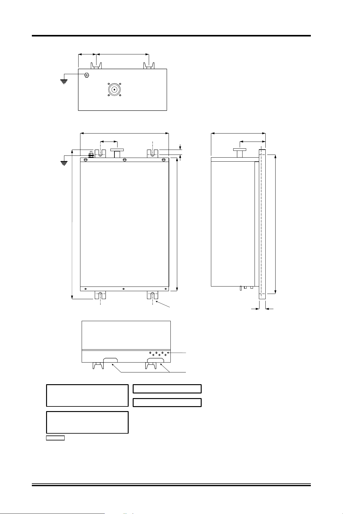
TOP VIEW
85
BETWEEN FIXING CENTRES
KH1252
Chapter 4
250
720
88.4
420
19
645
15.8mm SLOT
250
122.6
25
670
BETWEEN
FIXING
CENTRES
SYNC. & VIDEO SOCKETS
CABLE ENTRIES
OPERATING TEMPERATURE RANGE
At Relative Humidity 0%: -15 C to +55 C
At Relative Humidity 95%: +40 C
COMPASS SAFE DISTANCES :-
Standard Compass
Steering Compass
CD-4100
o
o
1.9m (Grade I)
1.1m (Grade II)
Transmitter Weight : 30kg
o
Power Consumption : 140W
Figure 1 - Downmast Transceiver (CTX-A9): Installation Dimensions
Issue 1 Page 4.7
 Loading...