


201020
66129904148
CONTENTS
1. SAFETY PRECAUTIONS.................................................................
2. UNIT PARTS IDENTIFICATION.......................................................
3. OPERATING INSTRUCTIONS ........................................................
4. INSTALLATION INSTRUCTIONS.....................................................
5. TROUBLESHOOTING .....................................................................
Inside you will find many helpful hints on how to use and maintain your air
conditioner properly. Just a little preventive care on your part can save you
a great deal of time and money over the life of your air conditioner. You'll find
many answers to common problems in the chart of troubleshooting tips.
If you review the chart of Troubleshooting Tips first, you may not need to
call for service at all.
Contact the authorised service technician for repair or maintenance of this unit.
Contact the installer for installation of this unit.
The air conditioner is not intended for use by young children or infirmed persons
without supervision.
Young children should be supervised to ensure that they do not play with the
air conditioner.
If the power cord is to be replaced, replacement work shall be performed by
authorised personnel only.
Installation work must be performed in accordance with the national wiring
standards by authorised personnel only. Wrong connection can cause overheating
!
CAUTION
Read This Manual
1
2
5
6
13
17
This air conditioner should be installed in accordance with AS/NZS 3000:2000
and your electricity suppliers rules.
There are local council rules regarding maximum allowable noise levels emitted
by air conditioners.
or fire.
To prevent injury to the user or other people and property damage, the following
instructions must be followed.
Incorrect operation due to ignoring of instructions may cause harm or damage.
The seriousness is classified by the following indications.
2
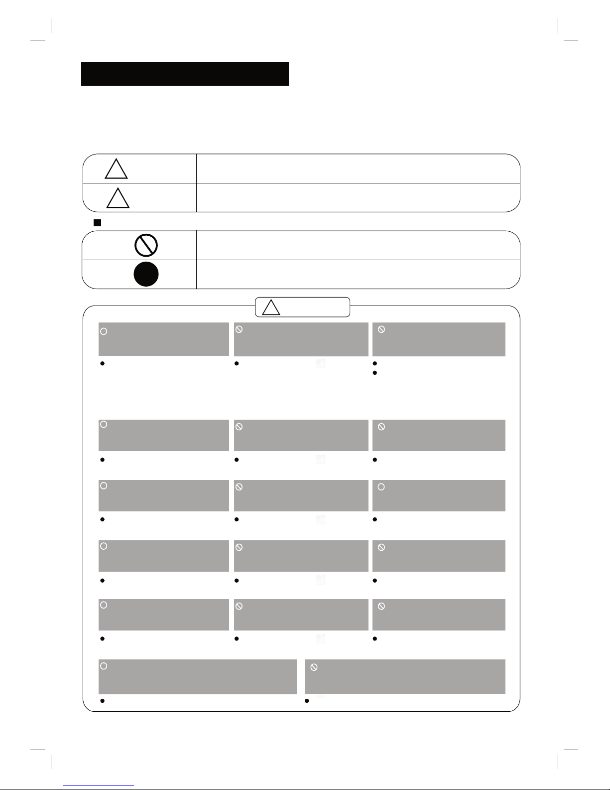
SAFETY PRECAUTIONS
This symbol indicates the possibility of death or serious injury.
Meanings of symbols used in this manual are as shown below.
!
!
WARNING
Always do this.
Never do this.
!
CAUTION
This symbol indicates the possibility of injury or damage to property.
Plug in power plug
properly.
Do not modify power cord
length or share the outlet
with other appliances.
Always ensure effective
earthing.
Unplug the unit if strange
sounds, smell, or smoke
comes from it.
Keep firearms away.
Ventilate room before operating air
conditioner if there is a gas leakage from
another appliance.
Otherwise, it may cause electric
shock or fire due to excess heat
generation.
It may cause electric shock or
fire due to heat generation.
Incorrect earthing may cause
electric shock.
It may cause fire and electric
shock.
It may cause fire.
It may cause explosion, fire and burns.
It may cause electric shock or fire
due to heat generation.
It may cause electric shock.
It may cause failure of unit
or electric shock.
It may cause fire and electric
shock.
It may cause fire and electric
shock.
It may cause electric shock or fire.
If the power cord is damaged, it
must be replaced by the manufac turer or an authorised service
centre or a similarly qualified per son in order to avoid a hazard.
This could harm your health.
Incorrect installation may cause
fire and electric shock.
It may cause electric shock.
It may cause an explosion or fire.
It may cause failure and electric shock.
Do not operate or stop the
unit by inserting or pulling
out the power plug.
Do not operate with wet
hands or in damp
environment.
Do not allow water to run
into electric parts.
Do not use the socket if it is
loose or damaged.
Do not use the power cord
close to heating appliances.
Do not damage or use an
unspecified power cord.
Do not direct airflow at
room occupants only.
Always install circuit
breaker and a dedicated
power circuit.
Do not open the unit
during operation.
Do not use the power cord near
flammable gas or combustibles, such
as gasoline, benzene, thinner, etc.
Do not disassemble or modify unit.
!
!
!
!
!
!
WARNING
!
!
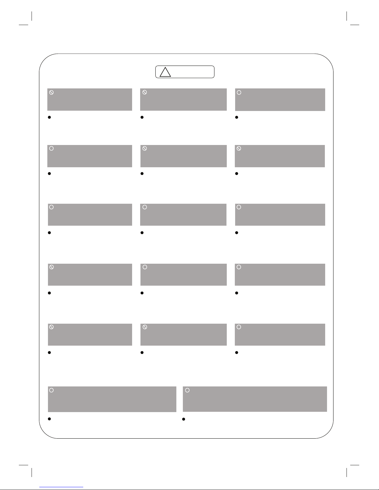
!
CAUTION
When the air filter is to be
removed, do not touch the
metal parts of the unit.
It may cause an injury.
Do not clean unit when
power is on as it may cause
fire and electric shock, it may
cause an injury.
Operation with windows
opened may cause wetting
of indoor and soaking of
household furniture.
When the unit is to be
cleaned, switch off, and turn
off the circuit breaker.
Stop operation and close
the window in storm or
hurricane.
Use caution when unpacking and
installing.
Do not clean the air
conditioner with water.
Water may enter the unit and
degrade the insulation. It may
cause an electric shock.
This could injure the pet or
plant.
It may cause electric shock
and damage.
Do not put a pet or house
plant where it will be
exposed to direct air flow.
Hold the plug by the head
of the power plug when
taking it out.
Ventilate the room well when
used together with a stove,
etc.
An oxygen shortage may occur.
Do not use this air conditioner to
preserve precision devices, food,
pets, plants, and art objects.
It may cause deterioration of
quality, etc.
It may cause failure of product
or fire.
Do not use for special
purposes.
Turn off the main power
switch when not using the
unit for a long time.
If water enters the unit, turn the unit off at the power
outlet and switch off the circuit breaker. Isolate
supply by taking the power-plug out and contact a
qualified service technician.
3
!
!
!
!
!
!
!
It may cause failure of
appliance or accident.
Appearance may be
deteriorated due to change
of product color or
scratching of its surface.
Do not place obstacles
around air-inlets or inside
of air-outlet.
Do not use strong detergent such as wax or
thinner but use a soft cloth.
If bracket is damaged, there
is concern of damage due to
falling of unit.
There is danger of fire or
electric shock.
Ensure that the installation bracket of
the outdoor appliance is not damaged
due to prolonged exposure.
Do not place heavy object on the
power cord and ensure that the cord
is not compressed.
Operation without filters may
cause failure.
It contains contaminants and
could make you sick.
Always insert the filters
securely. Clean filter once
every two weeks.
Do not drink water drained
from air conditioner.
!
!
!
Sharp edges could cause injury.
It may cause electric shock and damage.
Safety
Precautions
Prior to Operation
Preparing for operation
Usage
Cleaning and maintenance
Service
Operating Temperature
4
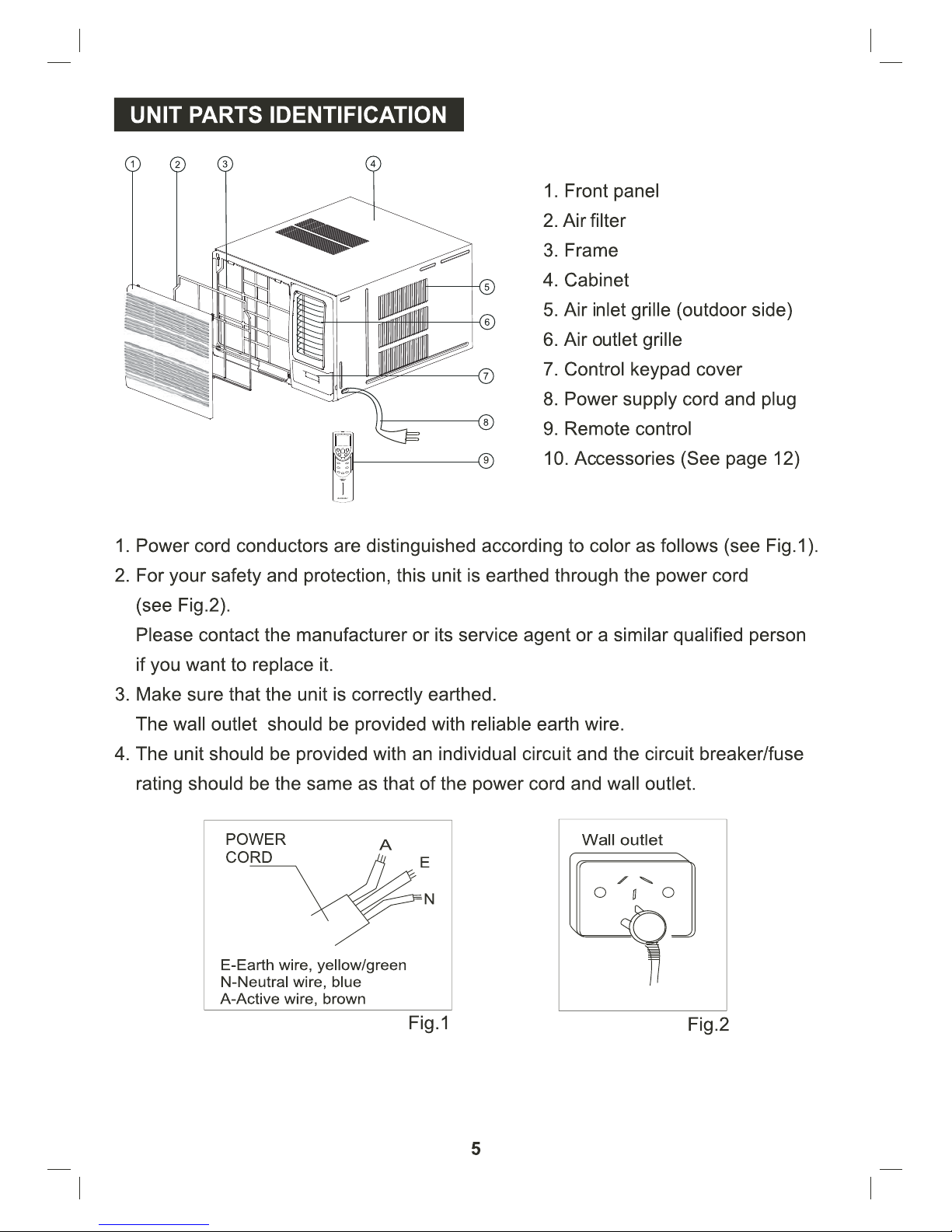
1. Contact an installation specialist for installation.
2. Plug in the power plug properly.
3. Do not use a damaged or non-standard power cord.
4. Do not share the same outlet with other appliances.
5. Do not use an extension cord.
6. Do not start/stop operation by plugging/unplugging the power cord.
1. Exposure to direct airflow for an extended period of time could be hazardous
to your health. Do not expose occupants, pets, or plants to direct airflow for
extended periods of time.
2. Due to the possibility of oxygen deficiency, ventilate the room when used
together with stoves or other heating devices.
3. Do not use this air conditioner for non-specified special purposes (e.g.
Preserving precision devices, food, pets, plants, and art objects). Usage in
such a manner could harm such property.
1. Do not touch the metal parts of the unit when removing the filter. Injuries can
occur when handling sharp metal edges.
2. Do not use water to clean inside the air conditioner. Exposure to water can
destroy the insulation, leading to possible electric shock.
3. When cleaning the unit, first make sure that the power and circuit breaker are
turned off.
For repair and maintenance, contact your authorised service dealer.
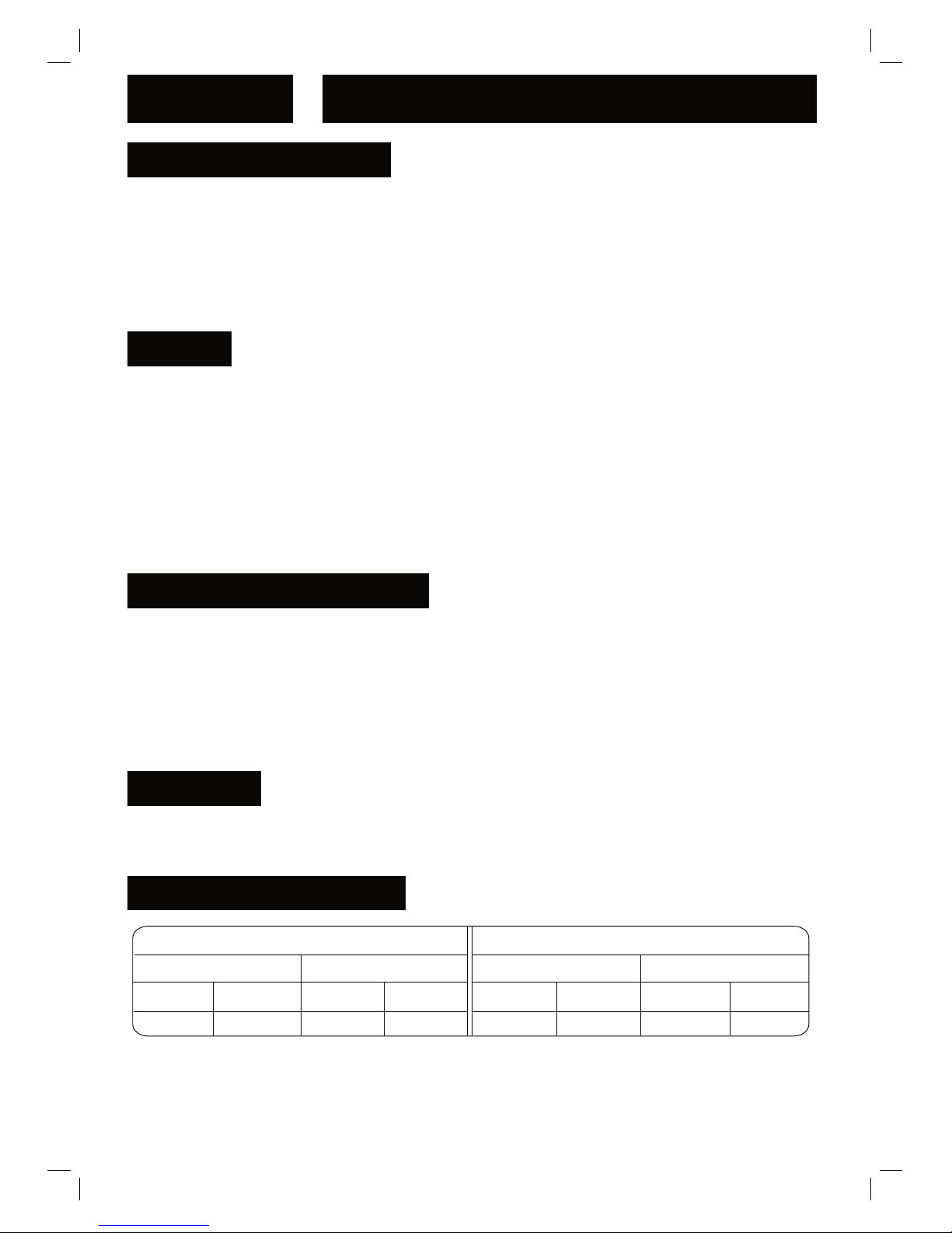
COOLING MODE
INDOOR OUTDOOR
INDOOR OUTDOOR
HEATING MODE
MAX. MIN. MAX. MIN.
OO
32 C 17 C
OO
27 C 10 C
OO
43 C 17 C
OO
24 C 1 C
MAX. MIN. MAX. MIN.
Note: Performance may be reduced outside of these operating temperatures.
CLOCK SWING
TIMER ON TIMER OFF
ENERGY
SAVER
SLEEP
LIGHT
FAN
ON OFF
MODE

OPERATING INSTRUCTIONS
Controls
Vent Control
Revers e Cycle Models
Cooling Only Models
The vent control is located above the control knobs. (see the following figures).
For maximum cooling efficiency, CLOSE the vent. This will allow internal air
circulation. OPEN the vent to discharge stale air.
The electronic control keypad will look like one of the following:
To open the vent, set the lever to the right position
To close it, set the lever in the left position.
OPEN
6
VENT
CLOSE
( 9,000BTU/h Models)
( 9,000BTU/h Models)
SW IN
FILTER
FAN
MO D
POWER
LOW
AUTO
COOL
DRY
FAN
TIMER
SW IN
FILTER
FAN
MO D
POWER
LOW
AUTO
COOL
DRY
FAN
TIMER

beside
There is no green indicator light for “Auto” mode. When you select “Auto”
mode, a beep will sound indicating this “MODE” option was selected.
1/2
1/2
AUTOˈ
A beep will sound indicating that this command is opera-
tional.
within
0~10 hours and 1 hour increments within 10~24 hours.
within 0~10 hours and 1 hour decrements
within 10~24 hours.
TIMER:
Press the "TIMER" keypad to activate the auto start/auto stop timer function.
Auto start/stop programs can be set from 1/2~24 hours. Each depression of the
"TIMER" keypad will increase the selected time in 1/2 hour increments within
0~10 hours and 1 hour increments within 10~24 hours.

This mode is used to decrease the humidity in the room.
OO
The temperature setting are adjustable between 16 C to 30 C . Cooling begins
O
automatically when the room temperature is 1 C above the set point, and stops
O
when the room temperature is 1 C below the set point. The fan will not stop running.
OO
The temperature settings are adjustable between 16 C to 30 C in heating mode.
the fan speed is optional.
When heating stops, there may be a slight delay of 30 seconds for the fan
For the cooling only models, after selecting “AUTO” by “MODE” keypad,the unit
will select the appropriate operating mode from FAN, COOL or DRY based upon the
temperature difference between the actual and desired room temperature.
For the cooling and heating models,after selecting “AUTO” by “MODE” keypad,the
unit will select the appropriate operating mode for Cool,Heat or Dry based upon the
temperature difference between the actual and desired room temperature.The default
is 20
o
C,the default cooling temperature set point is 25oC.
motor to stop.
Note: This Function can only be activated by remote control, Please refer to remote
operating instruction for more detail information
heating temperature set point
FILTER:
This feature is a reminder to clean the Air Filter (See Air Filter) for more efficient
operation.The light will illuminate after 250 hours of operation.To reset after cleaning
the filter, press the “FILTER” button and the light will go off.
DEFROST:
Under heating mode, when there is “H1” on the LED display indicates the unit is under
defrost function. In this case, any set on main unit or remote controller will not be
carried out until the defrost is completed.
FAILURE INDICATOR DISPLAY:
Indicates a malfunction of the indoor room temperature sensor
Indicates a malfunction of the evaporator temperature sensor
Indicates a malfunction of the outdoor condenser temperature sensor
When one of the above malfunctions occurs, turn off the unit, and check for
any obstructions. Restart the unit, if the malfunction is still present, turn off
the unit and unplug the power cord. Contact the manufacturer or its service
agents or a similar qualified person for service.
'
'
'
'
'
'
8

LIGHT:
Turn the unit LED light on or off only.
ENERGY SAVER:
Activate the “ENERGY SAVER” mode.
CLOCK:
Press this button to set clock.
CLOCK SWING
TIMER ON TIMER OFF
ENERGY
SAVER
SLEEP
LIGHT
FAN
ON OFF
MODE

(23 ft)
TIMER OFF:
Press the "TIMER OFF" button to activate the auto stop timer function. The method
of setting is the same as above for TIMER ON.
TIMER ON :
Press the "TIMER ON" button to activate the auto start timer function. Auto start
can be set from 1/2-24 hours. At unit off, press "TIMER ON" button,"HOUR ON"
on the display will blink and during 5 seconds blinking, the value can be adjusted by
pressing + or - button, every press of this button, 1/2 hour will be increased or
decreased, but continuously press the + or - button, 2 seconds later, the value
will be changed quickly, 1/2 hour will be increased in every 1/4 second automatically
by the remote controller. During blinking, press the "TIMER ON" button to confirm
the time. After "TIMER ON" set up, when repressing the "TIMER ON" button, the
"TIMER ON" setting will be canceled.

In this mode, the fan will continue to run for 1 minute after compressor shuts off.
ENERGY SAVER:
Press “ENERGY SAVER” to activate or disactivate the ENERGY SAVER Function.
Press +and - buttons simultaneously to lock or unlock the keypad. If the remote controller
is locked, the icon will be displayed on it, in that case, press any button, the mark will
flicker for three times. Repress the combination to unlock.
About switch between Fahrenheit and Centigrade
Under status of unit off, press MODE and - buttons simultaneously to switch
ćand
INTRODUCTION FOR SPECIAL FUNCTION
ABOUT LOCK
Press this button at unit On, the light on the main unit will be turned on or off. Light On is
defaulted when power on.
LIGHT:
Press this button, the clock can be set up, icon blinks. Within 5 seconds, the value
can be adjusted by pressing + or - button, if continuously press this button for 2 seconds
above, in every 1/2 seconds, one minute will be increased, if you are still pressing the button
after ten minutes increased, ten minutes will be increased every 1/2 seconds. Druing
blinking, repress the Clock button, icon will be constantly displayed and it denotes the
setting succeeded.
CLOCK

12

13

14
1. To avoid vibration and noise, make sure the unit is installed securely and firmly.
2. Install the unit where the sunlight does not shine directly on the unit.
If the unit receives direct sunlight, build an awning to shade the cabinet.
3. There should be no obstacle, such as a fence or wall, within 50cm from the back of the
cabinet because it will prevent heat radiation of the condenser.
Restriction of outside air will greatly reduce the cooling and heating (reverse cycle models
only) efficiency of the air conditioner.
4. Install the unit with a slight angle down towards the rear to allow condensate to run to the
(about 10mm or 1/4 bubble with level).
5. Install the unit with its bottom portion 75~150cm above the floor level.
6. The power cord must be connected to an independent circuit. The yellow/green wire must
be earthed.
7. In some light construction walls there may be a requirement for the addition of a foam or
rubber strip between the air conditioner housing and the wall cavity. The addition of a foam
or rubber strip will assist in isolating transmission of normal operation vibration into the wall.
rear of the air conditioner
Over 50cm
About 10mm
FENCE
AWNING
75-150cm
Over 50cm
About 10mm
FENCE
AWNING
75-150cm
All side louvres of the cabinet must not be obstructed and must be positioned outside of
the structure.
CAUTION
Select the best location
INSTALLATION INSTRUCTIONS

Installations of the unit into the wall
AIR IN
AIR IN
AIR OUT
100mm minimum
OPTION A
AIR IN
LOUVRE
BRICK
WALL
O
45 BRICK CUT AWAY
TO CLEAR LOUVRES
FRONT
AIR OUT
AIR INAIR IN
TOP
VIEW
O
45 BRICK CUT AWAY
TO CLEAR LOUVRES
100mm
BRICK
WALL
100mm
OPTION B
15
Installation of the unit into the Housing
1. Remove the front panel as per the installation instruction
and slide the unit into the housing until it is firmly against
the rear of the housing. Care is required to ensure the foam
sealing strips on the inside of the housing remain in position.
2. Connect the air conditioner to the power and position
excess cord length beneath the air conditioner base.
3. Engage the chassis fixing brackets into the bottom housing
rail and secure to the base with the screw provided.
4. Re-install the front panel as per the installation instruction.
5. Switch the unit on. Check for operation of the unit and
check for vibration in the installation.
6. Fit the drain pan to the housing and run a drain line to a
suitable location if required.
Alternative method of installation if external
support cannot be provided.
FLASH OR SEAL AROUND EXTERNAL
WALL FRAME OR ARCHITRAVE
STURDY TIMBER
FRAME
TIMBER FRAMED
WALL OR PARTITION
SOLID TIMBER SUPPORT
STEADYING BRACKET
(ONE PER SIDE)
DRAIN PAN
ENSURE LOUVRES
ARE ENTIRELY
OUTSIDE THE WALL
Hole in the wall
Unit housing
Foam strip
Step 1
Remove the air conditioner from it's packaging, remove fixing
screws and slide the air conditioner out of it's housing (Refer
to Installation Steps).
Step 2
Prepare the hole in the wall so that the bottom of the housing
is well supported, the top has minimum clearance and the air
inlet louvres have clearance as shown in options A and B.
Holes from the outside through to the cavity should be sealed.
The housing should slope down towards the rear by about
10mm to allow water formed during operation to drain.
Step 3
Install the housing into the wall and secure. Ensure the
foam seals are not damaged. Flash, seal or fill gaps
around the inside and outside to provide satisfactory
appearance and protection against the weather, insects
and rodents.
Note: To assist in isolating transmission of normal operation
vibration into the wall, use the foam strip.
Fit the foam strip between the air conditioner housing and
the wall cavity.
Installation of the Housing
NOTE: UNIT MAY BE SUPPORTED BY A
SOLID FRAME FROM BELOW OR
BY A HANGER FROM A SOLID
OVERHEAD SUPPORT.
Preferred method of installation into a timber
framed wall, partition or window.
FLASH OR SEAL AROUND EXTERNAL
WALL FRAME OR ARCHITRAVE
STURDY TIMBER
FRAME ALL
AROUND UNIT
TIMBER FRAMED
WALL OR PARTITION
EXTERNAL SUPPORT
FRAME AT BALANCE
POINT OF A/C
ALTERNATIVELY, BRACKETS
AS ILLUSTRATED IN FOLLOWING
DIAGRAM MAY BE USED.
DRAIN PAN

1. Remove the one fixing screws from the frame (See Fig.5).
2. Grasp the left corner of the frame's underside, then loosen the frame and carefully disconnect
the co
nnector (See Fig.6).
1. Hold the slot under the front panel, then uplift it outwards, and remove the front panel (See Fig.3).
2. Pinch the handle under the air filter and make the air filter arched, remove it from the slot from
underside to upside (See Fig.4).
Fig. 3
Fig.
4 Fig. 5
Fig.
6
Fig.
7
Fig.
8
16
In-line Connector
1. Remove the two fixing screws on the chassis fixing brackets (9,000Btu/h and 12,000 Btu/h models,
See Fig.7) or remove the two fixing screws on the side of cabinet (≥16,000Btu/h model) or
remove the two screws on the back of cabinet (if fitted. These screws are not needed to install
in later installation), then remove the chassis fixing brackets.
2. Grasp the handle on the chassis and carefully slide the air conditioner out of the cabinet
(See Fig.8).
3. Remove shipping pad (if fitted ) from around compressor before operation (Failure to do so
may damage the Compressor ) And make sure the discharge points to the drain pan are
aligned before the chassis is pushed into the cabinet (See Fig.9).
4. Push the unit chass is into the cabinet (See Fig.10).
5. Fix the chassis with the screws previously removed as they were prior to removal.
1. Install the frame making sure not to interfere with the
temperature sensor (See Fig.11).
2. Fix the screws on the frame (See Fig.5). For ı12,000 Btu/h
models, the screws are supplied with the unit.
1. Install the air filter into the frame's slot from upside to
underside (See Fig.4).
2. Hang the front panel on the frame's buckle, then press the
front panel into the frame's slot until you hear a click (See Fig12).
Fig. 9 Fig. 10
Foam
Compressor
(Top view)
Fig. 11
Fig.
12

Abnormal Operation
TROUBLESHOOTING
Normal Operation
Air conditioner
does not cool or
heat as it should
Air conditioner
does not start
Air conditioner
freezing up
Problem
Possible Causes
What To Do
The air conditioner is
unplugged.
Make sure the air conditioner plug is
pushed completely into the outlet and
switched on.
Troubleshooting Tips
Save time and money! Review the chart below first and you may not need to call for service.
You may hear a pinging noise caused by water being picked up and thrown against the
condenser on rainy days or when the humidity is high. This design feature helps remove
moisture and improve cooling efficiency.
Water will collect in the base pan during high humidity or on rainy days. The water may
overflow and drip from the outdoor side of the unit.
The fan may continue to operate when the compressor has cycled off.
The fuse is blown/circuit
breaker is tripped.
Check the house fuse/circuit breaker box
and replace the fuse or reset the breaker.
Power failure.
If power failure occurs, switch off and
disconnect /unplug the power cord. When
power is restored, reconnect (plug in) the
power cord, switch on the power and wait
3 minutes to restart the air conditioner to
prevent tripping of the compressor overload.
Airflow is restricted .
Make sure there are no curtains, blinds,
or furniture blocking the front of the air
conditioner.
Clean the filter at least every 2 weeks.
See the operating instructions section.
When the air conditioner is first turned on you
need to allow time for the room to cool down.
Check for open furnace floor registers and
cold or hot air returns.
Set the air conditioner's vent to the closed
position.
See Air Conditioner Freezing Up below.
The air filter is dirty.
The room may have been
hot.
Cold/hot air is escaping.
Coils have iced up.
Ice blocks the air flow and
stops the air conditioner
from cooling the room.
Set the fan at MED or HIGH until the
ice melts.
17

Warranty
FOR SALES IN AUSTRALIA AND NEW ZEALAND
APPLIANCE
: [ELECTROLUX KELVINATOR WINDOW WALL AIR
CONDITIONER]
This document sets out the terms and conditions of product
warranties for Electrolux branded appliances. It is an
important document. Please keep it with your proof of
purchase documents in a safe place for future reference
should you require service for your Electrolux appliance.
General Terms and Conditions
1. In this warranty
(a) 'Electrolux' means Electrolux Home Products Pty Ltd
ABN 51 004 762 341 in respect of Appliances purchased
in Australia and Electrolux (NZ) Limited in respect of
Appliances purchased in New Zealand;
(b) 'Appliance' means any Electrolux product purchased by
you accompanied by this document;
(c) 'Warranty Period' means
(i) where you use the Appliance for personal, domestic
or household purposes in Australia the period of “60”
months and in New Zealand the period of “60” ;
(ii) where you use the Appliance for commercial
purposes, in Australia the period of “24” months and
in New Zealand the period of “24” months, (if the
period stated is 0 months you are not covered by this
product warranty)
(iii) for Air conditioner accessories that are supplied as
part of an Appliance by Electrolux the period of 12
months;
following the date of original purchase of the Appliance;
(d) 'you' means the purchaser of the Appliance not having
purchased the appliance for re-sale, and 'your' has a
corresponding meaning.
2. This warranty only applies to Appliances purchased and used
in Australia or New Zealand and is in addition to (and does
not exclude, restrict, or modify in any way) any nonexcludable statutory warranties in Australia or New Zealand.
3. Electrolux warrants that, when dispatched from an Electrolux
warehouse, the Appliance is free from defects in materials
and workmanship for the Warranty Period.
4. During the Warranty Period Electrolux or its Authorised
Service Centre will, at no extra charge if your appliance is
readily accessible without special equipment, and subject to
these terms and conditions, repair or replace any parts which
it considers to be defective. You agree that any replaced
Appliances or parts become the property of Electrolux. This
warranty does not apply to light globes, batteries, filters or
similar perishable parts. Electrolux or its ASC may use
reconditioned parts to repair your appliance.
5. Parts and Appliances not supplied by Electrolux are not
covered by this warranty.
6. Where you are within an Electrolux service area, this
warranty covers the cost of transport of the Appliance to and
from Authorised Service Centres of Electrolux and travelling
costs for representatives of the Authorised Service Centre to
and from your home or business. If you are outside an
Electrolux service area, you will bear these costs. For
information about whether you are within an Electrolux
service area, please phone 13 13 49 in Australia, or 0800 10
66 10 in New Zealand.
7. Proof of purchase is required before you can make a claim
under this warranty.
8. You may not make a claim under this warranty unless the
defect claimed is due to faulty or defective parts or
workmanship. Electrolux is not liable in the following
situations (which are not exhaustive):
(a) The Appliance is damaged by:
(i) accident
(ii) misuse or abuse, including failure to properly maintain
or service
(iii) normal wear and tear
(iv) power surges, electrical storm damage or incorrect
power supply
(v) incomplete or improper installation
(vi) incorrect, improper or inappropriate operation
(vii) insect or vermin infestation.
(b) The Appliance is modified without authority from
Electrolux in writing.
(c) The Appliance's serial number or warranty seal has been
removed or defaced.
(d) The Appliance was serviced or repaired by anyone other
than Electrolux or its Authorised Service Centres.
9. This warranty, the contract to which it relates and the
relationship between you and Electrolux are governed by the
law applicable in the Australian State where the Appliance
was purchased or the law applicable in New Zealand if the
Appliance was purchased in New Zealand. Where the
Appliance was purchased in New Zealand for business
purposes the Consumer Guarantee Act does not apply.
Limitation of Liability
10. To the extent permitted by law:
(a) Electrolux excludes all warranties other than as contained
in this document;
(b) Electrolux shall not be liable for any loss or damage
whether direct or indirect or consequential arising from
your purchase, use or non-use of the Appliance.
11. Provisions of the Trade Practices Act and State consumer
legislation in Australia, and the Consumer Guarantees Act,
the Sale of Goods Act and the Fair Trading Act in New
Zealand, imply warranties or conditions, or impose
obligations, upon Electrolux which cannot be excluded,
restricted or modified. To the extent permitted by law, the
liability of Electrolux (if any) arising out of or in relation to the
Appliance or any services supplied by Electrolux shall be
limited (where it is fair and reasonable to do so),:
(a) in the case of Appliances, at its option, to the
replacement or repair of the Appliances or the supply of
equivalent products or the payment of the cost of
replacing the Appliances or having the Appliances
repaired or of acquiring equivalent Appliances. Upon
being replaced, parts and Appliances become the
property of Electrolux; or
(b) in the case of services, at its option, to the supply of the
services again or the payment of the cost of having the
services re-supplied;
and in the case of Appliances or services supplied in New
Zealand, loss or damage whether direct or indirect or
consequential that is reasonably foreseeable.
Privacy
You acknowledge that in the event that you make a warranty
claim it will be necessary for Electrolux and its Authorised
Service Centres to exchange information in relation to you to
enable Electrolux to meet its obligations under this warranty.
Important Notice
Before Calling a Service Technician please check carefully the operating instructions, service booklet and the warranty terms and conditions.
FOR SERVICE
OR TO FIND THE ADDRESS OF
YOUR NEAREST STATE SERVICE
CENTRE IN AUSTRALIA
Please call 13 13 49
For the cost of a local call (Australia only)
SERVICE AUSTRALIA
ELECTROLUX HOME PRODUCTS
FOR SPARE PARTS
OR TO FIND THE ADDRESS OF
YOUR NEAREST STATE SPARE
PARTS CENTRE IN AUSTRALIA
Please call 13 13 50
For the cost of a local call (Australia only)
FOR SERVICE
OR TO FIND THE ADDRESS OF
YOUR NEAREST AUTHORISED
SERVICE CENTRE IN NEW
ZEALAND
Free call 0800 10 66 10
SERVICE NEW ZEALAND
ELECTROLUX HOME PRODUCTS
FOR SPARE PARTS
OR TO FIND THE ADDRESS OF
YOUR NEAREST SPARE PARTS
CENTRE IN NEW ZEALAND
Free call 0800 10 66 20

66129904148
 Loading...