

Page 1

Inverter Split-type Room Air Conditioner
Installation Manual
KSV26HRB, KSV35HRB, KSV53HRB,
KSV62HRB, KSV70HRB, KSV80HRB
Refrigerant R410A
Page 2
warning
Do not install yourself.
Incorrec t installation could c ause injury due to fire,
electric al shock, the unit fa lling or leakage of water.
Consult the d ealer from whom you purch ased the
unit or author ised installer.
Perform the in stallation secur ely referring to the
installation instruction.
Incorrec t installation could c ause a personal injur y
due to fire, elect ric shock, the unit f alling or leakage
of w ater.
Install the u nit securely in a plac e which can bear the
weight of the u nit.
If installed i n a structurally u nsound location, the u nit
could fall causing injury.
Perform ele ctrical work accord ing to the installatio n
manual and b e sure to use a dedicated ci rcuit.
If the capaci ty of the power circui t is insufficient or
there is incom plete electrical w ork, it could result in a
fire or an elect ric shock.
Use the speci fied wires to connec t the indoor and
outdoor uni ts. Securely atta ch the wires to the
terminal boa rd connecting sec tions so the stress of
the wire is not ap plied to the section s.
Incorrec t connection and fix ing could cause a fire.
Check that th e refrigerant gas do es not leak after
installatio n is complete.
Leak refriger ant could be a hazard to heal th and the
environment.
Unit may not per form to full capacit y and life of unit
may reduce.
Be sure to use the pa rts provided or spe cified parts
for the insta llation work.
The use of defec tive parts cou ld cause an injury du e
to a fire, electr ic shock, the unit falli ng etc.
Perform the dr ainage/piping work acc ording to the
installation instruction.
If there is a defec t in the drainage/pip ing work, water
could leak from t he unit and household g oods could
get wet or be damag ed
Operating temperature
Cooling Mode
Indoor
Outdoor
Max. Min. Max. Min.
32°C 17°C
50°C 18°C
Heating Mode
Indoor Outdoor
Max. Min. Max. Min.
27°C 17°C 34°C -15°C
Note: Optimum performa nce will be achieved within these
operating temperatures.
Please read the user ma nual before installation and caref ully
store in a handy place fo r later reference. Inside you will
find many helpful hint s on how to install and test the air
conditioner properly.
Electrical w ork must be performed by a li censed electrician.
Be sure to use the corre ct rating of the power plug and main
circuit for the mod el to be installed.
Incorrect in stallation due to ignoring of the in struction will
cause harm or da mage, and the seriousness is cla ssified by
the following indications.
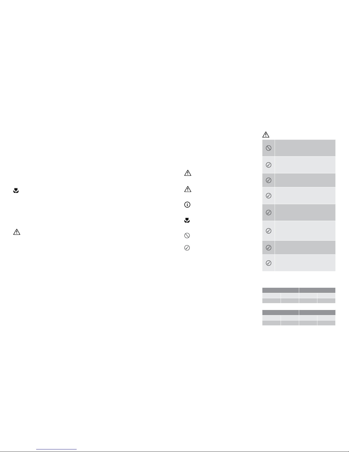
Meanings of symb ols used in this manual are shown belo w:
warning
This symbol indicates information concerning your
personal safety
caution
This symbol in dicates information on how to avoid
damaging the appliance
tips and information
This symbol in dicates tips and information a bout
use of the applia nce
environmental tip
This symbol in dicates tips and information a bout
economical and ecological use of the appliance
This symbol in dicates never to do this
This symbol in dicates always do this
Important safety instructions
2 Contents Kelvinator Air Conditioning
Congratulatio ns and thank you for choosing our Inver ter
split-type roo m air conditioner. We are sure you will find
your new air conditio ner a pleasure to use. Before you use
the air conditione r, we re commend that you read through
the entire user man ual, which provides the descri ption of
the air conditioner and its functions.
To avoid the risks that are alway s present when you use an
electric al appliance, it is important t hat the air conditioner
is installed cor rectly and that you read the safe ty instructions
carefully to avoid misu se and hazards.
We recommend that you kee p this instruction book let
for future referenc e and pass it on to any future owner s.
After unpack ing the air conditioner please c heck it is not
damaged. If in doubt , do not use the air conditioner bu t
contact your l ocal Electrolux Custom er Care Centre.
environmental tip
Information on disposal for users
• Most of the pac king materials are recyclable.
Please dispose of t hose materials through your loca l
recycling dep ot or by placing them in appropriate
collection containers.
• If you wish to disc ard this air conditioner, please contac t
your local autho rities and ask for the correc t method
of disposal.
caution
• The air condit ioner is not intended for use by young
children or infirmed persons without supervision.
• Young children should be su pervised to ensure that th ey
do not play with the air c onditioner.
• Contact a n authorised installer for in stallation of this unit.
• Contact a n authorised service te chnician for repair or
maintenance of this uni t.
• If the power cord is to b e replaced, replacement work
shall be performed by authorised personnel only.
• Installatio n work must be performed i n accordance
with the national w iring Standards by authorised
personnel only.
Conditions of use
This appliance is in tended to be useed in household an d
similar applications such as:
• Staff kitchen are as in shops, offices and other wo rking
environments
• Farm houses
• By clients in hotels, motel s, and other residential
type environments
• Bed and breakfas t type environments
Safety instructions
Warning .........................................................................................3
Caution ..........................................................................................3
Installation instructions
Select the rig ht place for installation .........................................6
Indoor unit installation ................................................................9
Outdoor unit installation ...........................................................10
Refrigerant pipe connection ...........................................10
Electrical work .................................................................15
Air purging
Air purging with va cuum pump ................................................18
Safety and leaka ge check .........................................................19
Test running.....................................................................19
Congratulations Contents
Kelvinator Air Conditioning Important safe ty instruc tions 3
Page 3
Kelvinator Air Conditioning typical installation 54 before installation Kelvinator Air Conditioning
caution
• Use a stud nder to loc ate studs to prevent
unnecessa ry damage to the wall.
• A minimum pipe run o f 3 metres is required to
minimise vibration & excessive noise.
• Two of the A, B and C directio ns should be free
from obstructions.
• This illustrati on is for explanation purposes o nly.
• Copper lines mus t be insulated indepen dently.
KSV26HRB
KSV26HRC
KSV35HRB
KSV35HRC
KSV53HRC
KSV62HRC
KSV70HRB
KSV70HRC
KSV80HRC
INDOOR
Remote control
(Including Holder)
1 1 1
Battery
2 2 2
Tubing plug
1 1 1
Self-tappin g Screw
ST4.2*25 TA
5 10 10
Manual
1 1 1
OUTDOOR
Drainage plug
- 3 3
Drainage Joint and seal
1 1 1
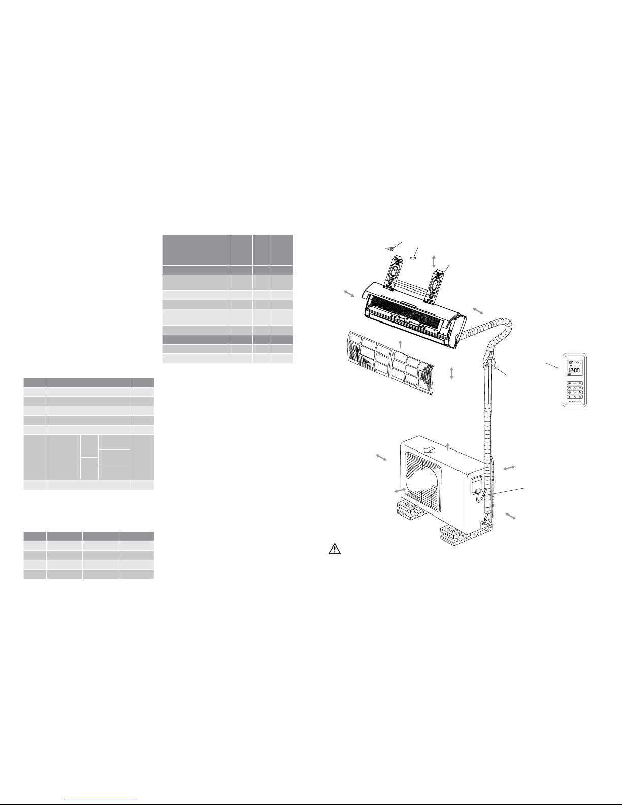
Before Installation Typical installation (shows minimum clearances required for ef fective operation and access
for service and maintenance)
Tools needed for installation
Level gauge
Screwdriver
Electric dri ll, Hole core drill ( 65mm)
Flaring tool set
Specified torque wrenches: 1.8kgf.m,
4.2kgf.m, 5.5kgf.m, 6.6kgf.m
(different dep ending on model No.)
Spanner (half union)
Hexagonal wrenc h (4mm)
Gas-leak detec tor
Vacuum pump
Gauge manifold
Users manual
Thermometer
Multimeter
Pipe cutter
Measuring tape
Items required for installing the unit
Number Name of Accesso ries Qty
1
Installation Plate 1
2
Clip Anchor 8
3
Self-tappin g Screw A 8
4
Seal (See page 8 for d etails) 1
5
Drain Joint (See p age 8 for details) 1
6
Connecting
pipe Assembly
Liquid
Side
φ
6.35
Parts
you must
purchase
(A minimum
pipe wallthickness
of 0.7mm
is required.)
φ
9.52
(<3.5k W mode l)
Gas
Side
φ
12.70
(>=3.5kW mo del)
7
Remote control 1
Note: Excluding the parts that a re provided with the unit
detailed above all other pa rts must be purchased
separately.
Pipes needed for installa tion (Purchase separately according
the following table).
Diameter
2.6kW 3.5kW&5.3kW >=6.2kW
6.35mm
Yes Yes No
9.35mm
Yes No Yes
12.7m m
No Yes No
16.0 mm
No No Yes
Yes: Pipe needed on model. No: Pipe not n eeded on model.
Loop the
connective
cable.
Air Outlet
15cm clearance
2
1
3
6
7
2.0m below
60cm above
Air Filter
30cm left
12cm right
30cm behind
60cm right
2.0m front
A
B
C
12cm left
Page 4

• Ens ure that the clearance around the ba ck of the unit
is more than 30c m and more than 30cm on the lef t side.
The front of the unit s hould have more than 2.0m
of clearance and th e connection side (right side) sho uld
have more than 60c m of clearance.
• Do not p lace animals and plants in the path of t he air
inlet or outlet.
• Take the air condi tioner weight into account and sele ct
a place where noise an d vibration will not be an issue.
• Sel ect a place so that the warm air an d noise from the
air conditioner d o not disturb neighbours.
Rooftop installation
• If th e outdoor unit is installed on a roof s tructure, be sure
to level the unit.
• Ens ure the roof structure and an choring method are
adequate for the uni t location.
• Co nsult local codes regarding roo ftop mounting.
• If th e outdoor unit is installed on roof s tructures or
external walls, t his may result in excessive noise and
vibration, and may al so be classed as a non servic eable
installation.
Tools needed for ins tallation
• Level ga uge
• Screwd river
• Elec tric drill, Hole core drill (65mm)
• Flaring to ol set
• Sp ecied torque wrenches: 1.8kgf.m, 4.2kgf.m, 5.5kgf.m,
6.6kgf.m (different d epending on model No.)
• Spann er (half union)
• Hexago nal wrench (4mm)
• Gas-l eak detector
• Vacuum pu mp
• Gauge man ifold
• User ma nual
• Thermometer
• Multimeter
• Pipe cu tter
• Measuring
Installation instructions Piping length elevation
Select the r ight place for in stallation
Read completely, then follow s tep by step.
Indoor unit
More than 15cm clearance
More than
12cm
More than
12cm
More than 2.0m
• Do not ex pose the indoor unit to heat or steam.
• Sel ect a place where there are no obs tacles in front
or around the unit.
• Make su re that condensation drainag e can be
conveniently routed away.
• Do not i nstall near a doorway.
• Ens ure that the space on the left and r ight of the unit
is more than 12cm.
• Us e a stud nder to locate studs to pre vent unnecessary
damage to the wall.
• Th e indoor unit should be installe d on the wall at
a height of 2.0m or more f rom the floor.
• Th e indoor unit should be installe d allowing a minimum
clearance of 15cm from t he ceiling.
• Any v ariations in pipe length will/may req uire adjustment
to refrigerant ch arge.
• Th ere should not be any direct sunligh t. Otherwise,
the sun will fade th e plastic cabinet and affec t its
appearance. If unavo idable, sunlight prevention should
be taken into consideration.
Outdoor unit
More than 2.0m
More than 30cm
More than 60cm
More than 30cm
• If an a wning is built over the outdoor unit to pre vent
direct sunligh t or rain exposure, make sure that heat
radiation from the c ondenser is not restric ted.
6 Installation instructions Kelvinator Refrigeration Kelvinator Refrigeration piping length elevation 7
Capacity
Piping
Standard
Length(m)
Max.
Length
B (m)
Max.
Length
A (m)
Additional
Refrigerant
(g/m)
Gas Liquid
2.6kw
3/8”
9.53mm
1/4”
6.35mm
5
8 20 20
3.5kw
1/2”
12.7m m
1/4”
6.35mm
5
8 20 20
5.3kw
1/2”
12.7m m
1/4”
6.35mm
5
10 25 20
6.2kw
5/8”
16.0 mm
3/8”
9.53mm
5
10 25 40
7.0 kw
5/8”
16.0 mm
3/8”
9.53mm
5
10 25 40
8.0kw
5/8”
16.0 mm
3/8”
9.53mm
5
10 25 40
Piping lengt h under 5m Piping lengt h of 5m or more
caution
Capacity i s based on standard length a nd maximum
allowance len gth is on the basis of reliabilit y.
Oil trap should b e installed every 5~7 metres.
When the conn ecting pipe is longer tha n 5 metres,
additional re frigerant should be added i nto the unit
according to the ab ove table through the service p ort
on the “LO” valve on the outdo or unit.
Page 5

Kelvinator Air Conditioning installation 98 installation Kelvinator Air Conditioning
Upper Hook
Lower Hook
Cushioning
material
5. Piping and wrapping
Bundle the tubing, c onnecting cable, and drain h ose with
tape securely a nd evenly as shown page 13.
• Bec ause the condensed water f rom rear of the indoor
unit is gathered in t he ponding box and is piped out of
the room, do not put any thing else in this box.
Connecting
pipe
Wrapping belt
Drain hose
Indoor unit Ponding box
Pipe room
Connecting
cable
caution
• Conne ct the indoor unit rst, t hen the outdoor unit.
• Do not a llow the piping to be exposed out fro m the back
of the indoor unit.
• Be care ful not to let the drain hose become s lack.
• Heat ins ulate the connecting piping.
• Be su re that the drain hose is located a t the lowest side
of the bundle. Locat ing at the upper side can caus e drain
pan to overflow insid e the unit.
• Neve r cross connect or inter win d the power wire with
any other wiring.
• Run th e drain hose sloped downward to d rain out the
condensed water smoothly.
3. Connecting Pipe an d Drainage Installation
1 Run the d rain hose sloping downward. Do not i nstall the
drain hose as illus trated below.
Do not block water flow with a rise.
Do not put the end of the
drain hose into water.
2 Whe n connecting an extension d rain hose, insulate the
connecting pa rt of the extension drain ho se with a shield
pipe, do not let the dra in hose become slack.
Connecting pipe
1 For the l eft-hand and right-hand piping, rem ove the pipe
cover from the side pan el.
2 For the re ar-right-hand and rear-left-hand piping, i nstall
the piping as shown. B end the connecting pipe to be laid
at a height of 43mm or le ss from the wall.
3 Fix t he end of the connecting pipe. (Refer to T ightening
Connection i n REFRIGERANT PIPING CONNECTION)
Right-hand piping
Side Part cover
Left-hand piping
Rear-right piping
Rear-left piping
.
.
.
.
.
.
.
.
.
.
.
.
.
.
.
.
.
.
.
.
.
.
.
.
.
.
.
.
.
.
.
.
.
.
.
.
.
.
.
.
.
.
.
.
.
.
.
.
.
.
.
.
.
.
.
.
.
.
.
.
.
.
.
.
.
.
.
.
.
.
.
.
.
.
.
.
.
.
.
.
.
.
.
.
.
.
.
.
.
.
.
.
.
.
.
.
.
.
.
.
.
.
.
.
.
.
.
.
.
.
.
.
.
.
.
.
.
.
.
.
.
.
.
.
.
.
.
.
.
.
.
.
.
.
.
.
.
.
.
.
.
.
.
.
.
.
.
.
.
.
.
.
.
.
.
.
43
Indoor unit outline
Connecting pipe
Installation
(7.0kw) and (8.0kw) model)
A
40
B
Right rear side
refrigerant
pipe hole 65
Installation plate
Indoor unit outline
Left rear side
refrigerant
pipe hole 65
15cm or more to ceiling
12cm or more
to wall
12cm or more
to wall
( (3.5kw) model, )<(6.2kw) model
<(3.5kw) model: (A: 710, B: 250/ A:790, B:265)
(3.5kw) model: (A: 790, B:265)
90
40
45
15cm or more to ceiling
Indoor unit outline
Installation plate
305
Right rear side
refrigerant
pipe hole 65
Left rear side
refrigerant
pipe hole 65
12cm or more
to wall
12cm or more
to wall
850
45
90
45
45
272
80
489
(>(6.2kw)model)
12cm or more
to the wall
to the wall
12cm or more
50
15cm or more to the ceiling
Indoor Unit Outline
380
Hooked Part
380
998
322
119
130
65
65
130
50
Above 12cm to
the wall
Above 12cm to
the wall
Above 15cm to
the ceiling
325
55
95
95
55
1250
815
257
178
55
58
Pipe hole
Hooked Part
Hooker Part
Pipe hole
Indoor unit outline
Indoor
Outdoor
5-7m m
Wall
B
Right rear side
refrigerant
pipe hole 65
12cm or more
to wall
Right rear side
refrigerant
pipe hole 65
12cm or more
to wall
90
45
to the wall
12cm or more
50
119
65
130
Above 12cm to
the wall
325
55
95
257
Pipe hole
2. Dri ll a hole in the wall
1 Determine hole
positions accord ing to
the diagram deta iled in
Fig.5. Drill one (1) hole
( 65mm) slanting slight ly
to outdoor side.
2 Alw ays use wall hole
conduit when dr illing
metal grid, metal p late
or the like.
Correct orientation
of Installation Plate
Indoor unit installation
1. Fi t the Installation Plate
1 Fit th e installation plate horizontally o n structural par ts
of the wall with spac es around the installation plate.
2 If the w all is made of brick, concrete or the li ke, drill eight
(8) 5mm diameter hole s in the wall. Insert Clip ancho r for
appropriate mounting screws.
3 Fit th e installation plate on the wall with e ight (8) type
“A” s cr ews .
Note: Fit the Installation Plate and drill holes i n the wall
according to the wall structure and corres ponding
mounting points on the in stallation plate.
(Dimensions are in “mm” unless otherwis e stated)
4. Indoor unit installation
1 Pass the pi ping through the hole in the wall.
2 Put th e upper claw at the back of the indoo r unit on
the upper hook of t he installation plate, move the indoor
unit from side to side to s ee that it is securely hooked.
3 Piping c an easily be made by lifting the in door unit
with a cushioning m aterial between the indoor un it
and the wall. Remove cushioning material after the
piping is finished.
4 Push t he lower part of the indoor unit u p on the wall,
Then move the indoo r unit from side to side, up and
down to check if it i s hooked securely.
Page 6

Kelvinator Air Conditioning refrigerant pipe connection 1110 installation/refrigerant pipe connection Kelvinator Air Conditioning
Bar
Copper pipe
Clamp handle
Red arrow mark
Cone
Yoke
Handle
Bar
"A"
Tightening Connection
• Align t he center of the pipes.
• Su fciently tighten the are nut w ith ngers, and
then tighten it wit h a spanner and torque wrench
as shown below.
Indoor unit tubing Flare nut Pipings
Outer diam.
Tightening torqu e
(Kg.m)
Additional Tig htening
Torque (Kg.m)
φ
6.35
1.6 2.0
φ
9.53
3.0 3.5
φ
12.7
5.0 5.5
φ
16.0
7.5 8.0
caution
• Exces sive torque can break nut dep ending on
installation conditions.
E: Check
• Comp are the ared work with the adjacent d iagram.
• If are i s found to be defective, cut of f the ared section
and do flaring work aga in.
Smooth all round
Improper flaring
Even length
all round
A: Cut the pipes and th e cable.
1 Use th e piping kit accessory (i f applicable) or pipes
purchased locally.
2 Meas ure the distance between t he indoor and the
outdoor unit.
3 Cut the pi pes a little longer than the me asured distance.
4 Cut the c able 1.5m longer than the pipe length .
B: Burr remova l
1 Com pletely remove all burrs from the cu t cross section
of pipe/tube.
2 Face th e end of the copper pipe/tube in a dow nward
direction as yo u remove burrs in order to avoid burrs
dropping into the tubing.
Pipe
Reamer
Face down
caution
C: Putting are nut o n
Remove flare nuts at tached to indoor and outdoor un it,
then put them on pip e/tube having completed burr rem oval
Note: It is not possible to put them on af ter flaring work.
Flare nut
Copper tube
D: Flaring work
• Car ry out aring work using aring to ol as shown below.
• Fir mly hold copper pipe in a die accord ing to the
dimension shown i n the table below.
Outer diam. (mm)
A(mm)
Max. Min.
φ
6.35
1.3 0.7
φ
9.53
1.6 1.0
φ
12.7
1.8 1.0
φ
16.0
2.4 2.2
Securing of outdoor unit
• An chor the outdoor unit with a bol t and nut 10 or 8
tightly and horizo ntally on a concrete or rigid mount.
Model A(mm) B(mm)
≤3.5kw
530 290
5.3kw
560 335
≥6.2kw
590 333
A
B
Air in let
Air out le t
Air in let
Drain joint installation
• If a d rain elbow is used, the unit should b e placed on
a stand which is t aller than 3cm.
• If th e unit is used in an area where temper ature
falls below 0
O
C for 2 or 3 days in succes sion, it is
recommended not to u se a drain elbow, as the drain
water may freeze and th e fan will not rotate.
• Fi t the seal into the drain elbow, then inse rt the drain
joint into the base pan ho le of the outdoor unit, rotate
90 degrees to se cure. Connect the drain joint w ith an
extension drai n hose (Locally purchased), in in stances
where you need to dra in condensed water away from
the unit.
Seal
Seal
Drain pipe
Drain joint
Base pan hole of
outdoor unit
Refrigerant pipe connection
1 Flaring work
Main cause for refr igerant leakage is due to defec ts in
the flaring work. C arry out correct flar ing work using the
following procedure:
Oblique
90 C
Roughness
Burr
Refrigerant pipe connection
Outdoor unit installation
Outdoor unit installation precautions
• Ins tall the outdoor unit on a rigid bas e to prevent noise
and vibration.
• Sel ect the air outlet direc tion so that discharged air is
not blocked.
• In c ase the installation locat ion is exposed to strong
winds, make sure the f an operates properly by put ting
the unit lengthw ise along the wall or by using a shield
to minimise wind exp osure.
• E specially in windy areas, inst all the unit to minimise
exposure to wind.
• For su spended installations, t he installation bracket
should follow with tec hnique requirement in the
installation brac ket diagram. The installation wall
should be solid bric k, concrete or of same constr uction,
or reinforced to minimise movement or vibration.
The connect ion between the wall bracket an d the
air conditioner s hould be firm, stable and reliable.
• Ens ure there are no obstacles whic h block ow air.
Strong
wind
Page 7

Kelvinator Air Conditioning refrigerant pipe connection 1312 refrigerant pipe connection Kelvinator Air Conditioning
For rear left piping
Note: When viewed from the front of the indoor u nit.
A: Route the indoor tubi ng and the drain hose to the
required pipi ng hole position in the direc tion of left.
Tubing retainer
B: Inser t the connecting cable i nto the indoor unit from
the outdoor uni t through the piping hole.
• Do not connect the cable to the ind oor unit.
• Make a small loop with the cable for easy
connection later.
C: Tape the drain hose and the co nnecting cable. Be sure
that the drain ho se is located at the lowest sid e of the
bundle. loca ting at the upper side can ca use drain pan
to overow insid e the unit.
Note: If the drain hose is routed ins ide the room, insulate
the hose with an insulation m aterial so that dripping
from “sweating” (condensation) will not damage
furniture or floors.
*Foamed polyethylene or equ ivalent is recommended.
G: Conne cting the piping to the indoo r unit and the drain
hose to drain pipe.
• Alig n the centre of the piping and suf ciently tighten the
flare nut by hand.
• Tighten the are nut with a wrench, in acc ordance with
the following table.
Outer
Diameter.
Tightening torqu e
(Kg.m)
Additional Tig htening
Torque (Kg.m)
1/4” (6. 35mm)
1.6 2.0
3/8 ” (9.5 3mm )
3.0 3.5
1/2” (12.7mm)
5.0 5.5
5/8” ( 16.0mm)
7.5 8.0
Indoor unit tubing Flare nut Pipings
• When ex tending the drain hose of the indo or unit,
install the dra in pipe extension as shown in
diagram below.
H: Wrap i n the insulation material arou nd the
connecting portion.
• Overlap t he connection pipe heat insu lation and the
indoor unit pipe hea t insulation material. Bind them
together with vi nyl tape so that there is no gap.
• Wrap the area w hich accommodates the rear pipin g
housing sect ion with vinyl tape.
• Bundle th e piping and drain hose together by w rapping
them vinyl tape ove r the range within they fit into the rear
piping housing section.
C: Tape the tubing, drain hose a nd the connecting cabl e.
Be sure that the dr ain hose is located at the lowes t side
of the bundle. Lo cating at the upper side ca n cause
drain pan to over ow inside the unit.
Note: If the drain hose is routed insid e the room, insulate the
hose with insulation material s o that dripping from “sweating”
(condensation) will not damag e furniture or floors.
*Foamed polyethylene or equ ivalent is recommended.
D: In sert the piping, drain hose a nd the connecting cabl e
into the piping hole.
Tubing retainer
E: Set the pi ping and the drain hose to the back o f the
chassis with t he tubing holder.
• Set the tubing retainer into position an d tighten screw.
Connecting
cable
F: Loc ating the indoor unit
• Hook the in door unit onto the upper por tion of
the installatio n plate (Engage the two hooks of the
installation plate i nto the openings at the rear top of
the indoor unit). Ensu re that the hooks are properly
seated on the inst allation plate by moving the indoor
unit left and rig ht.
• Press the lower left and right sid es of the unit against the
installation plate u nit until the hooks engage into the ir
slot (clicking sound).
Connection of pipes - Indoor
• Pre pare the indoor unit’s piping and drai n hose for
installation throug h the wall.
• Remove t he tubing retainer (see illustr ation below)
and pull the tubing an d drain hose away from chassis
(if required). For som e models this is not needed.
• Repl ace the tubing retainer in its or iginal position.
Tubing retainer
caution
When insta lling the indoor unit, be sure to re move the
relavant sec tions where required (see ad jacent diagram
for example). This wil l allow piping and cable routi ng to
be completed w ithout damaging the unit.
For rear right piping
Note: When viewed from the front of the indoor u nit.
A: Route in indoor tubi ng and the drain hose in the
direction o f rear right.
B: Inser t the connecting cable i nto the indoor unit from
the outdoor uni t through the piping hole.
• Do not connect the cab le to the indoor unit.
• Ma ke a small loop with the cable for eas y
connection later.
Rear left
Drain hose
Piping
Connecting cable
Rear right
Front
Page 8

Kelvinator Air Conditioning refrigerant pipe connection/electrical work 1514 refrigerant pipe connection Kelvinator Air Conditioning
Connect th e cable to the indoor unit
• Conn ect the cable to the indoor u nit by connecting the
wires to the termina ls on the control box individual ly
according to the outdoor unit connec tion.
(E nsure that the colour of the wires of the o utdoor unit
and the terminal num ber are the same as those of the
indoor unit.
1. Remove the elect rical box cover from the outdoor un it
by loosening the sc rew.
2. Connect wi res from the Indoor Unit to the termina ls on
the Outdoor Unit a s identified by their colours.
3. Secure the cab le onto the control board with the
cord clamp.
4. Be sure to install th e power supply for all models
according to the diagr am below. Be sure to firmly
connect the E arthing wire.
5. To waterproof, make a wire loop as det ailed in the
Installation Diag ram of Indoor and Outdoor Unit s.
6. Wrap wires (conduc tors) that were not connecte d with
insulating tape s o that they do not touch any electr ical
or metal part s.
Note:
• Wrong wire conn ection may cause some electrical par ts
to malfuncti on.
• The su pply voltage must be consistent with the rate
voltage of the air conditione r.
Connect th e cable to the indoor unit
Note: Before performing any ele ctrical work, turn off the main
power to the system.
Electrical Work
B: Finally, tighte n the are nut with torque wrenc h until
the wrench cli cks.
• Tig hten the are nut with a wrench, in acc ordance with
the following table.
Outer
Diameter.
Tightening torqu e
(Kg.m)
Additional Tig htening
Torque (Kg.m)
1/4” (6. 35mm)
1.6 2.0
3/8 ” (9.5 3mm )
3.0 3.5
1/2” (12.7mm)
5.0 5.5
5/8” ( 16.0mm)
7.5 8.0
H: Se t the piping and the drain hose to the b ack of the
chassis with t he tubing holder.
• Set t he tubing retainer into position an d tighten screw.
Tubing retainer
I: Reroute the pip ing and the drain hose across th e back
of the chassis, fo r rear left side external pa ssage.
J: Locating the ind oor unit
• Remove th e spacer.
• Hoo k the indoor unit onto the upper po rtion of
the installatio n plate (Engage the hooks of the
installation plate i nto the openings at the rear top
of the indoor unit.)
Ensure that the hook s are properly seated on the
installation plate b y moving the indoor unit left
and right.
• Pre ss the lower left and right sid es of the unit against the
installation plate u ntil the hooks engage into their sl ots
(clicking sound).
Connecting
cable
Connection of Pipes – Outdoor
A: Align the centre of th e piping and sufcient ly tighten
the are nut by han d.
D: In sert the piping, drain hose a nd the connecting cabl e
into the piping hole.
E: Indoor u nit installation
• Hang t he indoor unit from the hooks at t he top of the
installation plate.
• Ins ert a spacer between t he indoor unit and the
installation plate to s eparate the bottom of the unit f rom
the wall.
F: Con necting the piping to the ind oor unit and the drain
hose to drain pipe.
• Alig n the centre of the piping and suf ciently tighten the
flare nut by hand.
• Tig hten the are nut with a wrench, in acc ordance with
the following table.
Outer
Diameter.
Tightening torqu e
(Kg.m)
Additional Tig htening
Torque (Kg.m)
1/4” (6. 35mm)
1.6 2.0
3/8 ” (9.5 3mm )
3.0 3.5
1/2” (12.7mm)
5.0 5.5
5/8” ( 16.0mm)
7.5 8.0
• W hen extending the drain hose of t he indoor unit,
install the dra in pipe extension as shown in the
diagram below.
G: Wrap the i nsulation material around th e piping
connections
• O verlap the connection piping h eat insulation and the
indoor unit pipe hea t insulation material. Bind them
together with vi nyl tape so that there is no gap.
Terminal block of indoor u nit
model(2600k w)
model(5300k w)
model(7000k w)
model(8000k w)
Ele ctrical box
cover
Front P ane l
10mm
40mm
Code wire
model(3500k w)
model(6200k w)
Cord clamp
To outdoor unit
To outdoor unit
N
1
S
2(N)
S
L
L(1)
To outdoor unit
Cord clamp
L N S
Page 9

Kelvinator Air Conditioning electrical wor k/checking t he drainage and for ming piping 1716 electric al work Kelvinator Air Conditioning
Checking the drainage
A: To remove the front panel from the in door unit.
• Pull t he lower left and right sides of th e grille towards
you and lift it up.
B: To check the drain age
• Pour a glas s of water on the evaporator.
• Ens ure the water ows through the dra in hose of the
indoor unit with out any leakage and goes out the
drain exit.
C: Drain piping
• Th e drain hose should point downwa rd for easy
drain flow.
• Do not m ake drain piping similar to diagrams show n
below on the right.
Downw ard
sl ope
Water
leak age
Water
leak age
Water
leak age
Air
Do not
raise
Accumul ated
drain wa ter
Tip of drain hos e
dipped in water
Ditch
Les s tha n
50mm gap
Checking the drainage and forming
the piping
8 The followin g may be caused by voltage drop.
V ibration of a conductor, which will dam age the contact
point, fuse blowi ng, disturbance of the normal f unction
of the overload.
9 The means for d isconnection of a power su pply shall
be incorpora ted in the fixed wiring and have an air
gap contac t separation of at least 3m m in each active
(phase) conductor.
If a power plug is not to be use d, provide a Circuit Breaker/
Fuse between p ower source and the unit as shown in t he
diagram below.
40mm
10mm
L
S
N
To indoor unit
L(1)
L( 1)
L
S
N
9000Btu/h model(2.6 kw)
18000Btu/h model(5.3 kw)
12000Btu/h model(3.5 kw)
21000Btu/h model(6.2 kw)
Wire connector of outdoor unit
Wire-holding
board
To indoor unit To power supply
To indoor unit To power supply
caution
After confirmi ng the above conditions, prepare th e wiring
as follows:
1 Never fail to have an i ndividual power circuit s pecifically
for the air condi tioner. As for the method of wiring,
be guided by the ci rcuit diagram posted on the i nside
of the control cover.
2 The screws w hich fasten the wiring in the ca sing of
electric al fittings may come loose from vi brations
to which the unit i s subjected during the cou rse of
transport ation. Check them and make sure t hat they
are all tightly fas tened. If they are loose, it could c ause
burn-ou t of the wires.
3 Specica tion of power source.
4 Confirm that e lectrical capacit y of the installation
is sufficient.
5 Ensure that th e starting voltage is mai ntained at more
than 90 percen t of the rated voltage marked on the
name plate.
6 Confirm that th e cable thickness is as sp ecified in
the power source s pecification. Particu larly note the
relation between cable length and thickness (Refer
to page 14).
7 Always ins tall a Residual Current Device (R CD) in wet
or moist area.
Length of the pow er supply cord should be at lea st 1.8m.
Measure from the p ower supply cord entry of the c abinet
to the middle of the li ve pin of the plug.
Model Capacity
Power
Source
Circuit
Breaker
/Fuse
Rating
Wire Size
2.6kw
50Hz
220-24 0V
10A ≥1.0 mm
2
3.5kw
10A ≥1.0 mm
2
5.3kw
16A ≥1. 5mm
2
6.2kw
16A ≥1. 5mm
2
7.0 kw
16A ≥1. 5mm
2
8.0kw
20A ≥2.5 mm
2
Note: To be used as a guide only.
caution
Ensure that all elec trical work complies wit h relevant
Standards and Supply Authority Service Rules.
An individual br anch Circuit Breaker/Fuse must be use d with
this Air Conditio ner. See the table for electrical re quirements.
Note:
• Power Source and Power Cord specication s must
comply with requirements a bove.
• Circuit Breaker o r Fuse specied in this manual must be
installed in the power s upply circuit.
• For you r safety and protection, this unit is earthed
through the power cord plug wh en plugged into a
matching wall receptacle.
• Do no t connect two power cords together to sup ply
power to the air conditione r.
• Do not exte nd the power cable conductors by cutti ng.
Connect th e cable to the outdoor unit
A: Remove the cont rol cover from the unit by loosening
the sc rew.
Connect the w ires to the terminals on the control
board individually.
B: Sec ure the cable onto the control board w ith the
cord clamp.
C: Refix the control c over to the original position with
the sc rew.
D: Use a recognised ci rcuit breaker (See page 17) between
the power source an d the unit. An isolation device to
adequately disconnect all supply lines must be fitted.
Page 10

Kelvinator Air Conditioning air purging/test running 1918 checking the drainage and forming piping /air purging Kelvinator Air Conditioning
Safety and leakage check
Electric al safety check
Perform the elec trical safety chec k after completing
the installation:
1 Groundin g work
Af ter finishing grounding work , measure the grounding
resistance by vi sual detection and groundi ng
resistance tes ter.
2 Elec trical leakage check (p erforming during test r unning)
D uring test operation aft er finishing installation, the
service per son can use the electro probe and multimeter
to perform the e lectrical leakage che ck. Turn off the unit
immediately if leak age happens. Check and find out t he
solution ways till t he unit operates properly.
Gas leak chec k
1 Soap wate r method:
A pply a soap water or a liquid neutr al detergent on
the indoor unit connection or outdoor unit connections
by a soft brush to c heck for leakage of the connec ting
points of the piping . If bubbles come out, the pipes
have leakage.
2. Leak detector
Use the leak detector to che ck for leakage.
caution
A Lo packed v alve
B Hi pa cked valve
C and D are ends of indoo r unit connection.
Indoor unit
check point
D
B
C
A
Outdoor unit
check point
Cover
Test running
Perform test op eration after completing g as leak check at
the flare nut connec tions and electrical s afety check.
• Che ck that all tubing and wiring have been p roperly
connected.
• Che ck that the gas and liquid side ser vice valves are
fully open.
• Co nnect the power, press the ON/OFF but ton on the
remote control to turn t he unit on.
• Us e the MODE button to select COO L, HEAT, AUTO
and FAN to check if all the fu nctions work well.
Test running
When using th e vacuum pump
(For method of using a man ifold valve, refer to its
operation manual.)
1 Com pletely tighten the flare nuts, A, B, C, D, conn ect
the manifold valve ch arge hose to a charge port of the
low-pressu re valve on the gas pipe side.
2 Conn ect the charge hose connec tion to the
vacuum pump.
3 Fully open t he handle Lo of the manifold valve.
4 Ope rate the vacuum pump to evacuate. Af ter starting
evacuation, slight ly loose the flare nut of the Lo valve
on the gas pipe side a nd check that the air is entering
(O peration noise of the vacuum pu mp changes and a
compound meter in dicates 0 instead of minus)
5 Af ter the evacuation is complete, full y close the handle
Lo of the manifold valve a nd stop the operation of the
vacuum pump.
Ma ke evacuation for 15 minutes or more and check t hat
the compound mete r indicates -76cmHg (-1 x 10 Pa).
6 Turn the stem of t he packed valve B about 45
o
counterclock wise for 6~7 seconds after the gas sta rted
coming out, then tig hten the flare nut again. Make sure
the pressure dis play in the pressure indicator is a li ttle
higher than the atm osphere pressure.
7 Remove th e charge hose from the Low pressu re
charge hose.
8 Fully open t he packed valve stems B and A.
9 Secure ly tighten the cap of the packed valve.
Manifold va lve
Compound m eter
-76cmH g
Handle Lo
Handle Hi
Cha rge hos e
Cha rge hos e
Vacuum p ump
Pre ss ure ga uge
Low pre ss ure va lve
Air purging
Air purging
Air and moisture i n the refrigerant system have un desirable
effects as indicated below:
• Pre ssure in the system rises.
• Op erating current rises.
• Co oling or heating efciency d rops.
• Moi sture in the refrigerant circ uit may freeze and
block capillary tubing.
• Water may l ead to corrosion of parts in the
refrigeration s ystem.
Therefore, the indoo r unit and tubing between the
indoor and outdo or unit must be leak tested and
evacuated to remove any no ncondensables and
moisture from th e system.
Air purging wi th vacuum pump
• Preparation
Check that each tu be (both liquid and gas side tub es)
between the in door and outdoor units have bee n
properly conne cted and all wiring for the test r un has
been completed. Rem ove the service valve caps f rom
both the gas and the li quid sides on the outdoor unit.
Note that both the liqui d and the gas side service val ves
on the outdoor unit a re kept closed at this stage.
• Pipe l ength and refrigerant amou nt:
Connecting
pipe length
Air purging
method
Additional amou nt of
refrigerant to be charged
Less than 5m
Use vacuum
pump
–
More than 5m
Use vacuum
pump
(2.6-5.3kw) Models:
(Pipe length -5) x 20g/m
(6.2-8.0k w) Models: (Pipe
length-5) x 40g/m
• Wh en relocating the unit to another pla ce, perform
evacuation using v acuum pump.
• Make su re the refrigerant added into th e air conditioner
is in liquid form in any c ase.
Caution in han dling the packed valve
• Op en the valve stem until it hits aga inst the stopper.
Do not try to open i t further.
• Se curely tighten the valve stem ca p with a spanner or
the like.
• Valve s tem cap tightening torque (See Tighten ing torque
table on page 14).
Forming the pipe
A: Form the piping by wrap ping the connecting por tion
of the indoor un it with insulation material a nd secure it
with narrow vinyl t ape and wide vinyl tape.
• If you w ant to connect an additional d rain hose, the end
of the drain outlet s hould be routed above the ground.
Secure the drain h ose appropriately.
B: In cases w here the outdoor unit is ins talled below the
indoor unit perform the following.
• Tape the piping , drain hose and connecting c able from
down to up.
• Se cure the tapped piping along the ex terior wall using
saddle or equivalent.
C: In cases where th e outdoor unit is installe d above the
indoor unit perform the following.
• Tape the piping a nd connecting cable from d own to up.
• Se cure the taped piping along the ex terior wall. Form a
trap to prevent water e ntering the room.
• Fi x the piping onto the wall by saddle or equ ivalent.
Outdoor
unit
Indoor
unit
Refrigerant
Flare nut
Stopper
Cap
Valve body
Packed valve
Half union
Gas side
Liquid si de
A
C
D
B
Valve stem
Page 11

Kelvinator Air Conditioning notes 2120 test r unning Kelvinator Air Conditioning
Pump down
This is perfor med when the unit is to be relocate d or
the refrigeran t circuit is serviced. Pump D own means
collecting all ref rigerant in the outdoor unit w ithout loss
of refrigerant ga s.
caution
Be sure to perfor m Pump Down procedure with the uni t in
cooling mode.
Pump Down Procedure
1 Conn ect a low-pressure gaug e manifold hose to the
charge port on t he gas side service valve.
2 Ope n the gas side service valve hal fway and purge the
air from the manifold ho se using the refrigerant gas.
3 Close th e liquid side service valve (all the way i n ).
4 Turn on the unit ’s operating switch and star t the
cooling operation.
5 Whe n the low-pressure gauge readi ng becomes 1 to
0.5 kg/cm
2
(100~50kPa), fully close t he gas side valve
stem and then quic kly turn off the unit. At this t ime Pump
Down has been comp leted and all refrigerant gas will
have been collec ted in the outdoor unit.
• Wh en the ambient temperature is too l ow (lower than
17
O
C), the unit cannot be c ontrolled by the remote
control to run at cooli ng mode, manual operation can
be taken. Manual oper ation is used only when the
remote control is dis abled or maintenance is necess ary.
• Hold t he panel sides and lift the pan el up to an angle
until it remains fixed (clic king sound).
• Pre ss the Manual control button to se lect the AUTO
or COOL, the unit will op erate under Forced AUTO or
COOL mode (see User Ma nual for details).
• The tes t operation should last ab out 30 minutes.
Manual co ntrol
button
AUTO/COOL
Rated Capaci ty Te st (Cooling mode)
• Und er Cooling Mode, set the air condit ioner at High Fan
Speed and set the te mperature to 17
O
C, then press th e
TURBO button 6 time s within 10 seconds (be sure the
indoor unit buz zes 6 times). The system will enter Rated
Capacity Test mod e. The buzzer will keep on sounding
for 2 seconds whe n the fan speed reaches rating s peed
and the compres sor rotates at rating speed.
• Th e air conditioner can enter the Rate d Capacity Test
mode only when all t he above conditions are met.
• This mo de will automatically de-ac tivate after 5 hours.
• Du ring the Rated Capacity Test mode, if c ommon
protection, ambient temperature limitation for start-up
and rotation freq uency or de-frost protec tion occurs, the
test must be s topped.
Rated Capacity Test (Heating mode)
• Und er Heating Mode, set the air conditio ner at High Fan
Speed and set the te mperature to 30 C, then pres s the
TURBO button 6 time s within 10 seconds (be sure the
indoor unit buz zes 6 times). The system will enter Rated
Capacity Test mod e. The buzzer will keep on sounding
for 2 seconds whe n the fan speed reaches rating s peed
and the compres sor rotates at rating speed.
• Th e air conditioner can enter the Rate d Capacity Test
mode only when all t he above conditions are met.
• This mo de will automatically de-ac tivate after 5 hours.
• Du ring the Rated Capacity Test mode, if c ommon
protection, ambient temperature limitation for start-up
and rotation freq uency or de-frost protec tion occurs, the
test must be s topped.
Notes
Page 12

22 notes Kelvinator Air Conditioning
Notes
Kelvinator Air Conditioning warranty 23
This document sets out the terms and conditions of the product
warranties for Electrolux Appliances. It is an important document.
Please keep it with your proof of purchase documents in a safe place
for future reference should you require service for your Appliance.
1. In this warranty
(a) ‘acceptable quality’ as referred to in clause 10 of this warranty has
the same meaning referred to in the ACL;
(b) ‘ACL’ means Trade Practices Amendment (Australian Consumer
Law) Act (No.2) 2010;
(c) ‘Appliance’ means any Electrolux product purchased by you
accompanied by this document;
(d) ‘ASC’ means Electrolux’ authorised serviced centres;
(e) ‘Electrolux’ means Electrolux Home Products Pty Ltd of 163
O’Riordan Street, Mascot, NSW 2020, ABN 51 004 762 341 in
respect of Appliances purchased in Australia and Electrolux (NZ)
Limited of 3-5 Niall Burgess Road, Mount Wellington, in respect
of Appliances purchased in New Zealand;
(f) ‘major failure’ as referred to in clause 10 of this warranty has the
same meaning referred to in the ACL and includes a situation when
an Appliance cannot be repaired or it is uneconomic for Electrolux,
at its discretion, to repair an Appliance during the Warranty Period;
(g) ‘Warranty Period’ means:
(i) where the Appliance is used for personal, domestic or household
use (i.e. normal single family use) as set out in the instruction
manual, the Appliance is warranted against manufacturing
defects in Australia for 24 months and in New Zealand for the
period of 24 months, following the date of original purchase
of the Appliance and a further 36 months; in Australia if there is
evidence provided to Electrolux that the appliance was installed
by a licensed room air conditioner installer; in New Zealand if
there is evidence that the Appliance was installed according to
the Electrolux installation guidelines which can be inspected on
the Kelvinator website;
(ii) where the Appliance is used for commercial purposes (including
being used to directly assist a business or where the Appliance is
used in a multi-family communal or share type environment), the
Appliance will then be warranted against manufacturing defects
in Australia for 3 months and in New Zealand for 0 months,
following the date of original purchase of the Appliance.
(h) ‘you’ means the purchaser of the Appliance not having purchased
the Appliance for re-sale, and ‘your’ has a corresponding meaning.
2. This warranty only applies to Appliances purchased and used in Australia
or New Zealand and is in addition to (and does not exclude, restrict, or
modify in any way) any non-excludable statutory warranties in Australia
or New Zealand.
3. During the Warranty Period Electrolux or its ASC will, at no extra charge
if your Appliance is readily accessible for service, without special
equipment and subject to these terms and conditions, repair or replace
any parts which it considers to be defective. Electrolux or its ASC may
use remanufactured parts to repair your Appliance. You agree that
any replaced Appliances or parts become the property of Electrolux.
This warranty does not apply to light globes, batteries, lters or similar
perishable parts.
4. Parts and Appliances not supplied by Electrolux are not covered by
this warranty.
5. You will bear the cost of transportation, travel and delivery of the
Appliance to and from Electrolux or its ASC. If you reside outside of the
service area, you will bear the cost of:
(a) travel of an authorised representative;
(b) transportation and delivery of the Appliance to and from Electrolux or
its ASC,
In all instances, unless the Appliance is transported by Electrolux or an
Electrolux authorised representative, the Appliance is transported at the
owner’s cost and risk while in transit to and from Electrolux or its ASC.
6. Proof of purchase is required before you can make a claim under
this warranty.
7. You may not make a claim under this warranty unless the defect claimed
is due to faulty or defective parts or workmanship. Electrolux is not liable
in the following situations (which are not exhaustive):
(a) the Appliance is damaged by:
(i) accident
(ii) misuse or abuse, including failure to properly maintain or service
(iii) normal wear and tear
(iv) power surges, electrical storm damage or incorrect power supply
(v) incomplete or improper installation
(vi) incorrect, improper or inappropriate operation
(vii) insect or vermin infestation
(viii) failure to comply with any additional instructions supplied with the
Appliance;
(b) the Appliance is modied without authority from Electrolux in writing;
(c) the Appliance’s serial number or warranty seal has been removed
or defaced;
(d) the Appliance was serviced or repaired by anyone other than
Electrolux, an authorised repairer or ASC.
8. This warranty, the contract to which it relates and the relationship
between you and Electrolux are governed by the law applicable where
the Appliance was purchased. Where the Appliance was purchased in
New Zealand for business purposes the Consumer Guarantee Act does
not apply.
9. To the extent permitted by law, Electrolux excludes all warranties and
liabilities (other than as contained in this document) including liability for
any loss or damage whether direct or indirect arising from your purchase,
use or non use of the Appliance.
10. For Appliances and services provided by Electrolux in Australia, the
Appliances come with a guarantee by Electrolux that cannot be excluded
under the Australian Consumer Law. You are entitled to a replacement or
refund for a major failure and for compensation for any other reasonably
foreseeable loss or damage. You are also entitled to have the Appliance
repaired or replaced if the Appliance fails to be of acceptable quality and
the failure does not amount to a major failure. The benets to you given
by this warranty are in addition to your other rights and remedies under a
law in relation to the Appliances or services to which the warranty relates.
11. At all times during the Warranty Period, Electrolux shall, at its discretion,
determine whether repair, replacement or refund will apply if an
Appliance has a valid warranty claim applicable to it.
12. For Appliances and services provided by Electrolux in New Zealand,
the Appliances come with a guarantee by Electrolux pursuant to the
provisions of the Consumer Guarantees Act, the Sale of Goods Act and
the Fair Trading Act.
13. To enquire about claiming under this warranty, please follow these steps:
(a) carefully check the operating instructions, user manual and the terms
of this warranty;
(b) have the model and serial number of the Appliance available;
(c) have the proof of purchase (eg an invoice) available;
(d) telephone the numbers shown below.
14. You accept that if you make a warranty claim, Electrolux and its ASC
may exchange information in relation to you to enable Electrolux to meet
its obligations under this warranty.
Warranty
FOR SALES IN AUSTRALIA AND NEW ZEALAND
APPLIANCE: KELVINATOR SPLIT SYSTEM AIR CONDITIONER
Important Notice
Before calling for service, please ensure that the steps listed in point 13 above have been followed.
FOR SERVICE
or to nd the address of your nearest
state service centre in Australia
PLEASE CALL 13 13 49
For the cost of a local call (Australia only)
SERVICE AUSTRALIA
ELECTROLUX HOME PRODUCTS
www.electrolux.com.au
FOR SPARE PARTS
or to nd the address of your nearest
state spare parts centre in Australia
PLEASE CALL 13 13 50
For the cost of a local call (Australia only)
FOR SERVICE
or to nd the address of your nearest
authorised service centre in New Zealand
FREE CALL 0800 10 66 10
(New Zealand only)
SERVICE NEW ZEALAND
ELECTROLUX HOME PRODUCTS
www.electrolux.co.nz
FOR SPARE PARTS
or to nd the address of your nearest
state spare parts centre in New Zealand
FREE CALL 0800 10 66 20
(New Zealand only)
KSSAC_Warr_Apr11
Page 13

P/No. 1452635
© 2011 Elect rolux Home Pro ducts Pt y Ltd ABN 51 004 762 341
Print code: KFixINV UM_Jul11
If you’d like further information about Kelvinator
appliances, please visit your retailer, phone or email
our Customer Care team or visit our website.
telephone: 1300 363 640
fax: 1800 350 067
email: customercare@electrolux.com.au
web: www.kelvinator.com.au
Kelvinator. We are part of the Electrolux family.
Share more of our thinking at www.electrolux.com.au
 Loading...