

Page 1
Inverter Air Conditioner
Installation Manual
KSV25CRJ, KSV35CRJ, KSV71CRJ,
KSV25HWJ, KSV35HWJ, KSV50HWJ,
KSV71HWJ, KSV90HWJ,
KSD25HWJ, KSD35HWJ, KSD50HWJ,
KSD71HWJ, KSD90HWJ
Page 2
ENVIRONMENTAL TIPS
R300 refrigerant warning
Congratulations Contents
Congratulations and thank you for choosing our Inverter split
system room air conditioner. We are sure you will nd
your new air conditioner a pleasure to use. Before you use the air
conditioner, we recommend that you read through
the entire user manual, which provides the description of
the air conditioner and its functions.
To avoid the risks that are always present when you use an electrical
appliance, it is important that the air conditioner
is installed correctly and that you read the safety instructions
carefully to avoid misuse and hazards.
We recommend that you keep this instruction booklet
for future reference and pass it on to any future owner
After unpacking the air conditioner please check it is not damaged.
If in doubt, do not use the air conditioner but
contact your local Electrolux Customer Care Centre.
s.
Conditions of use
This appliance is intended to be used in household and similar
applications such as :
• staff kitchen areas in shops, ofces and other working
environments.
• farm houses.
• by clients in hotels, motels and other residential type
environments.
• bed and breakfast type environments.
This air conditioner is designed for and intended to be used in
normal domestic applications only.
Record model and serial number here:
Important Safety Instructions .................................................3
Installation instructions
Choosing a location to mount unit ...............................................4
Installation drawing .........................................................................5
Indoor unit installation
Installation plate mounting ............................................................6
Drilling the wall ................................................................................7
Connective pipe installation ..........................................................7
Drain piping ........................
.............................................................8
Outdoor unit installation
Location of outdoor unit ..............................................................10
Drain elbow installation ................................................................10
Refrigerant pipe connection ........................................................11
Flaring work ...................................................................................12
Test running
Air purging .....................................................................................15
Information servicing
Information servicing ....................................................................18
Warranty ......................................................................................23
Model number: ..................................................................................
Serial number: ..
.................................................................................
environment
Information on disposal for users
• Most of the packing materials are recyclable.
Please dispose of those materials through your local
recycling depot or by placing them in appropriate collection
containers.
• If you wish to discard this air conditioner, please contact your
local authorities and ask for the correct method
of disposal.
R32 refrigerant warning
This product uses R32 diuoromethane refrigerant, which is
a mildly ammable gas class 2.2 according according to
AS/NZS 5149 and must be handled by a refrigeration
mechanic with appropriate Australian refrigerant handling
licence.
2 Contents Kelvinator Air Conditioning
Page 3
WARNING
WARNING
WARNING
WARNING
TIPS & INFORMATION
ENVIRONMENTAL TIPS
Important safety instructions Notice for installation
Please read this installation manual and the user manual before
installation and carefully store in a handy place for later reference.
Inside you will find many helpful hints on how to install and test the
air conditioner properly.
Incorrect installation due to ignoring this instruction may cause
harm or damage, which may not be covered by warranty.
warning
This symbol indicates information concerning your personal safety
caution
This symbol indicates information on how to avoid damaging
the appliance
important
This symbol indicates tips and information about use of the
appliance
environment
This symbol indicates tips and information about economical and
ecological use of the appliance
caution
1 The unit must only be installed by a qualified refrigeration
mechanic and electrical work carried out by a qualified
electrician according to AS/NZS 3000 electrical installation
standard and in accordance with all local and national
regulations.
2 If the installation is not completed by a suitably licensed
person, any faults resulting from poor installation may not be
covered under warranty.
3 Means for disconnection must be provided in the fixed wiring
according to AS/NZS 3000 and local wiring regulations, install
a suitable isolation switch in an accessible location adjacent to
this air conditioner.
4 The temperature of the refrigerant circuit will be high, please
keep the interconnection cable away from the copper tube.
5 This appliance is not intended for use by persons (including
children) with reduced physical, sensory or mental capabilities,
or lack of experience and knowledge, unless they have
been given supervision or instruction concerning use of the
appliance by a person responsible for their safety.
Children should be supervised to ensure that they do not play
with the appliance.
caution
• Contact an authorised installer for installation of this unit.
• Contact an authorised service technician for repair or
maintenance of this unit.
• Installation work must be performed in accordance with the
national wiring standards by authorised personnel only.
warning
Before obtaining access to terminals, all supply circuits must be
disconnected.
Kelvinator Air Conditioning Important safety instructions 3
Page 4
Choosing a location to mount unit
Indoor unit
• Do not install the unit near any heat source, ammable gas or
steam.
• Choose a location where the air circulation is good, and where
there are no obstacles blocking the air ow.
• Select a place that will be convenient to run a drain to suitable
location outside.
• A place where noise prevention is taken into consideration.
• Do not install the unit near the door way.
• Ensure the restrictions on installation sp
unit installation drawings are met.
• Select a location which is
the device is not subjected to vibrations.
• The device should be installed at a distance of at least 1m
from all other electrical devices and installations, e.g. TV,
radio,computer, etc.
• Avoid installing in direct sunlight, if it's unavoidable consider
installing something to protect from direct sunlight.
enough for installation so that
ed in the indoor
reas
Your air conditioner is designed to condition the air for a certain
range of room size, please ensure the selection of your air
conditioner complies with the Kelvinator selection tool available
from www.kelvinator.com.au
This product uses mildly
of refrigerant require minimum room sizes. Please ensure that these
minimum room sizes are adhered to for standard installations (up
to 5m pipe length). If larger refrigerant charges than standard are
used then please consult AS/NZS 60335.2.40 to determine the safe
minimu
oor area for the installation.
ammable R32 refrigerant. Certain levels
Outdoor unit
• If an awning is built over the unit to prevent direct sunlight or
rain, be careful that heat radiation from the condenser is not
obstructed.
• Do not install outdoor unit in a location where the air outlet will
be directed on plants or animals as it may harm them.
• Make sure that there is suf
installation drawings.
• Do not place any obstacles which may cause a restriction of
the discharged air.
• Select a location which avoids causing a nuisance to
neighbours from noise and air emissions from device.
• Select a location which is suf
• Never cover the air inlets and outlets.
• The location must be suf
prevention of vibrations.
• There must be no risk presented by combustible gas or gas
escaping as a result of corrosion.
• Avoid a location where there is a high salt content.
• Avoid a location which is heavily exposed to dust.
• Avoid a location to which the general public have access.
nt space as spe ed in the
ntly well ventilated.
e r installation and the
Model Charge of R32 (g)
KSV25CRJ
KSV25HWJ
KSD25HWJ
KSV35CRJ
KSV35HWJ
KSD35HWJ
KSV50HWJ
KSD50HWJ
KSV71CRJ
KSV71HWJ
KSD71HWJ
KSV90HWJ
KSD90HWJ
800
850
1200
1300
2700
Minimum r area (m2)
N/A
N/A
2.00
2.44
6.95
4 Choosing a location Kelvinator Air Conditioning
Page 5
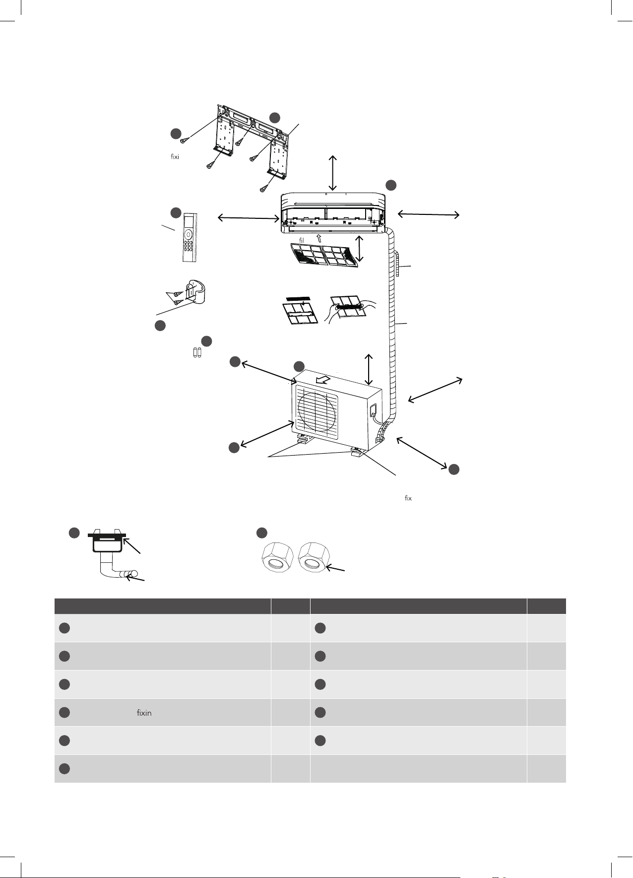
Installation drawing
Fig. 1
Before screwing the remote
controller holder to the wall,
make sure that control signals
are properly received by
indoor unit.
4
Installation plate ng screw
ST3.9x25(5)
Remote
control
5
6
2x AAA batteries
7
12cm or more
30cm or more
A
3
15cm or more
1
12cm or more
Air
2
ter
Air outlet
200cm
or more
Additional drain pipe
Wrapping tape (wrap the
insulation pipe with the tape
from bottom to top)
60cm
or more
30cm or more
200cm or more
60cm or more
B
In sites with poor drainage, use block bases
for outdoor unit. Adjust its height until the
unit is leveled. Otherwise, water leakage or
pooling of water may occur.
Where there is a danger of the
unit falling, use foot bolts to
.
Allow two of A, B and
C directions to be free
C
from obstructions.
8 9
Seal
Drain elbow
Flare nuts
Air conditioner Qty. Qty.
1
Indoor unit
2
Outdoor unit
3
Indoor unit mounting plate
4
Mounting plate g screws, ST3.9x25 5 or 8*
7
1
1
1
Battery (AAA 1.5V)
8
Drain elbow & seal 1
9
Flare nuts 2
10
Installation Manual 1
2
5
Remote controller 1
6
Remote controller holder
11
User manual 1
1
* 9kW models have 8 screws, other models have 5 screws.
NOTE: Appearance of outdoor unit and indoor unit may differ from some models. The actual shape shall prevail.
Kelvinator Air Conditioning Installation drawing 5
Page 6
Indoor unit installation
Remove the installation plate from the indoor unit. The installation
plate should be installed on a wall which can support the weight of
the indoor unit.
Indoor unit
Model
KSV25CRJ
KSV25HWJ
KSD25HWJ
KSV35CRJ
KSV35HWJ
KSD35HWJ
KSV50HWJ
KSD50HWJ
KSV71CRJ
KSV71HWJ
KSD71HWJ
KSV90HWJ
KSD90HWJ
dimensions
W x H x D (mm)
802 x 297 x 189
1080 x 335 x 226
1259 x 362 x 282
Weight (kg)
9.3
14.5
19.5
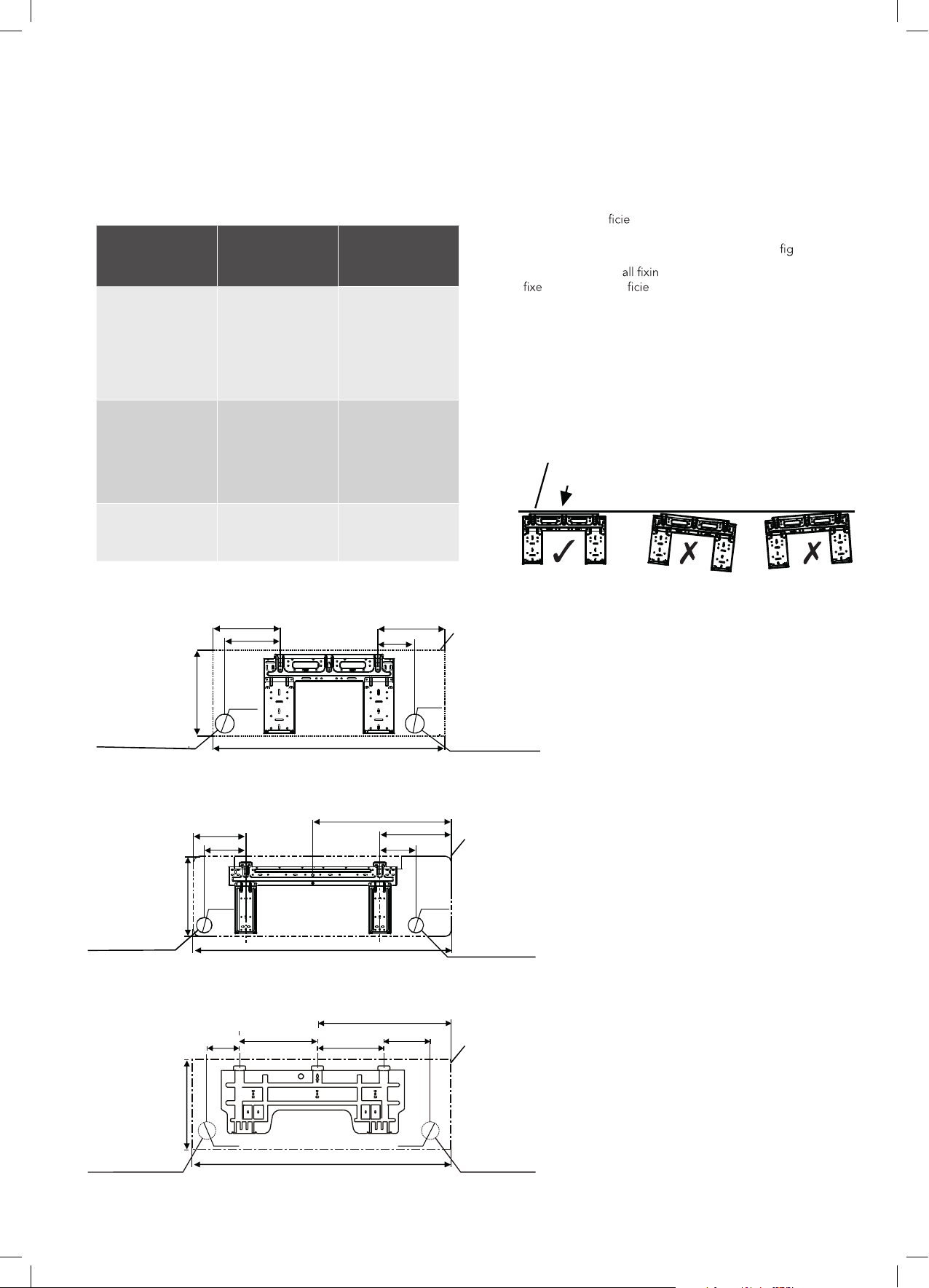
Installation plate mounting
ht tiF .1 e installation plate horizontally on structural parts of
the wall with suf
to accommodate the indoor unit and meet the clearance
requirements as per the assembly diagram, see
rppa esU .2 opriate w
d to which is suf nt to support the full weight of the
indoor unit.
3. Secure the installation plate to the wall with screws.
NOTE: Mount the installation plate and drill holes in the wall
according to the wall structure and corresponding mounting points
on the installation plate. The installation plate provided with the
machine differ from appliance to appliance. (Dimensions are in mm
unless otherwise stated).
Fig. 1
Correct orientation
of Installation Plate
nt space around the installation plate
ure 1.
gs suitable for the wall type being
Fig. 2
Left rear side
refrigerant
pipe hole
Left rear side
refrigerant
pipe hole
Ø65
Indoor unit
outline
Right rear side
232
192
297
Ø65
232
128
refrigerant
802
pipe hole
KSV25CRJ, KSV25HWJ, KSD25HWJ,
KSV35CRJ, KSV35HWJ, KSD35HWJ,
221
138
336
Ø75
298
149
578
Indoor unit
outline
Ø75
Right rear side
refrigerant
1080
pipe hole
KSV50HWJ, KSD50HWJ,
KSV71CRJ, KSV71HWJ, KSD71HWJ,
643.6
172
389
332
257
Indoor unit
outline
362
Left rear side
refrigerant
pipe hole
Ø90
1259
KSV90HWJ, KSD90HWJ,
6 Indoor unit installation Kelvinator Air Conditioning
Ø90
Right rear side
refrigerant
pipe hole
Page 7
Indoor unit installation
WARNING
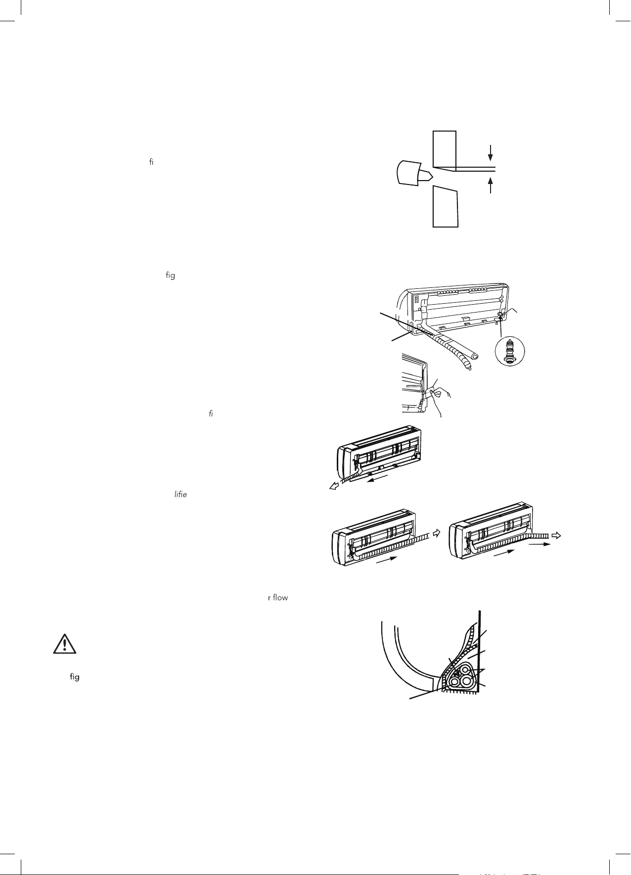
Drilling the wall
1. Choose the hole position to be either on the left or right side
of the installation plate and mark the position according to the
dimensions shown in
gure 2. Note most simple installation is
with hole on the right side.
2. Drill the piping hole with a hole core drill of the following
size: 65mm for models: KSV25CRJ, KSV25HWJ,
KSD25HWJ, KSV35CRJ, KSV35HWJ, KSD35HWJ,.
75mm for models: KSV50HWJ, KSD50HWJ, KSV71CRJ,
KSV71HWJ, KSD71HWJ.
90mm for models: KSV90HWJ, KSD90HWJ.
3. Drill the hole with slight (5-10mm) downward angle from indoor
to outdoor side so that the outside end is lower than the inside
end to help drainage, see
ure 3.
4. Insert a wall pipe or other means of protection to prevent the
pipes and electrical wires from toughing sharp edges within
the wall.
Connective pipe installation
1. For the left-hand and right-hand piping, remove the pipe
cover from the side panel.
2. For the right back and left back piping, install the piping
as shown.
NOTE: Bundle the pipes, connecting cable, and drain hose
with tape securely, evenly as shown in
gure 4 on the right.
The drain connection can be on the right side, left side or
both. If choosing to drain from both sides, another drain pipe
will need to be supplied by the installer. If choosing one side
drainage connection, make sure the drain hole on the other
side is well plugged. For 2.5kW & 3.5kW models, if choosing
left-hand or left-back piping, please choosing left side
drainage connection. The connection of t
must be connected by a qua
d installer in accordance with
he drain pipe hose
these instructions to prevent leakage.
3. Attach the drain hose to the underside of the refrigerant pipes
with adhesive vinyl tape.
4. Bundle the pipes, connecting cable, and drain hose with tape
securely, evenly as shown in Fig. 4.
5. Pass them through the wall hole.
6. Ensure that the drain hose has a continual downward fall from
the indoor side to the outdoor side to ensure the wat
e s
out smoothly. Failure to do this can result in water gathering in
and leaking from the indoor unit.
caution
• Do not put anything inside the condensate drain pan (refer to
ure 5), as this space is required to collect the condensate
prior to draining out of the indoor unit.
Fig. 3
Fig. 4
Fig. 5
Wall OutdoorIndoor
Move and tape
the drain hose
with piping in
a position as
mentioned in
Fig. below
Cover for
the piping
Cover for
the piping
Right piping
Left piping Left back
Indoor unit
Connective
cable
Drain hose
5-10mm
Cover for
the left piping
Rubber plug
piping
Condensate
drain pan
Pipe room
Connective
pipe
Wrapping
belt
Kelvinator Air Conditioning Indoor unit installation 7
Page 8
Indoor unit installation
W ARNING
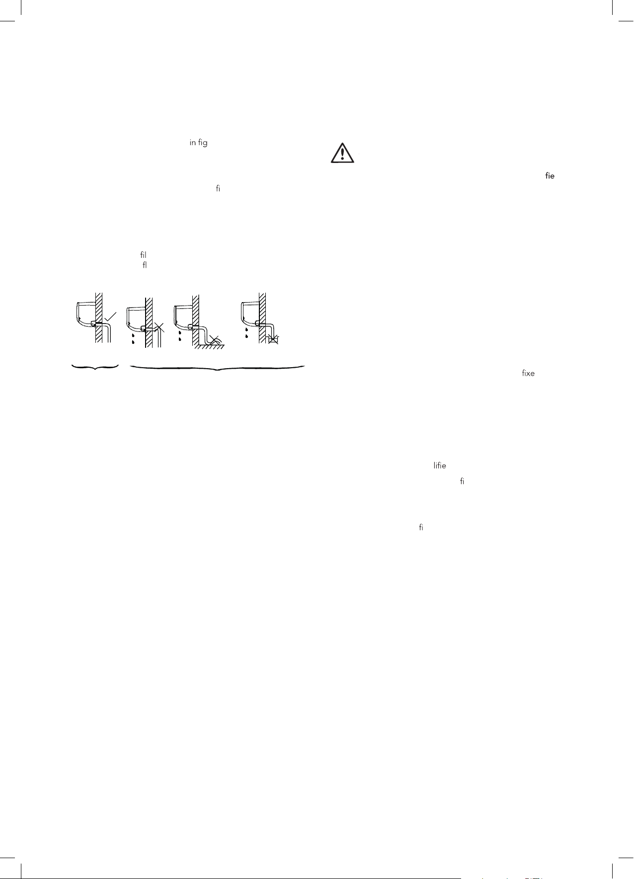
Drain piping
1. Run the drain hose as shown ure 6, ensuring it has a
constant downward fall.
2. The installer must supply a suitable drain hose extension to run
from the indoor unit drain hose to the desired drain location.
The drain hose extension should be
with the indoor unit drain hose, and secured in place with vinyl
tape. Ensure that the drain hose extension also has a continual
downward fall with an air gap at the bottom, and is drained to
a suitable location which will not cause damage to people or
property.
3. Remove the air
check the water
Fig 6.
Right Wrong
ter and pour some water into the drain pan to
ows smoothly.
No trap is permitted
tted and sealed tightly
Do not put the end of
drain hose into water
Connect the cable to the indoor unit
caution
Electrical installation must be completed by suitably quali d
electrician
Electric safety regulations for the initial installation
1. If there is serious safety problem about the power supply,
the technician should refuse to install the air conditioner and
explain to the client until the problem is solved.
2. Power voltage should be in the range of 90%–110%
of rated voltage.
3. The surge protector and main power switch with a 1.5 times
capacity of maximum. Current of the unit should be installed in
power circuit. Ensure the air conditioner is grounded well.
4. The appliance shall be installed in accordance with national
wiring regulations.
5. An all-pole disconnection device which has at least 3mm
clearances in all poles, the residual current device (RCD)
having a rated residual operating current not exceeding 30mA,
and disconnection must be incorporated in the
in accordance with the wiring rules. Refer to the table for
recommended circuit breaker rating for normal installation,
however national and local wiring regulations will prevail.
7. According to the attached electrical connection diagram
located on the panel of the indoor and outdoor unit to
connect the wire.
8. All wiring must comply with local and national electrical codes
and be installed by qua
9. Every wire must be connected
allowed to touch refrigerant tubing, the compressor, or any
moving parts.
10. Loose wiring will cause the terminal to overheat or result in
unit malfunction. A
sure all wiring is tightly connected.
This air conditioner will need to be installed on its own
11.
separate circuit, please refer to AS/NZS 3000 and local wiring
regulations for requirements.
12. For this air conditioner, the main power supply is fed to the
outdoor unit terminal block, ensure that the main power supply
wires running to the outdoor unit can carry the full current
of the air conditioner, which is stated on the rating label,
according
cable that connects from outdoor unit to indoor unit do not
carry the full compressor current, therefore 1.0mm
suitable for this application.
to national wiring regulations. The power and signal
d and skilled electricians.
rmly. No wire should be
re hazard may also exist. Therefore, be
d wiring
2
(or larger) is
8 Indoor unit installation Kelvinator Air Conditioning
Page 9

Indoor unit installation
Recommended circuit breaker rating
Model Circut breaker rating (Amps)
KSV25CRJ, KSV25HWJ,
KSD25HWJ
15
Fig 7.
active
brown
) 2(SN)L(1
neutral
blue
signal
white
earth (yellow
and green)
Terminal block
KSV35CRJ, KSV35HWJ,
KSD35HWJ
KSV50HWJ, KSD50HWJ
KSV71CRJ, KSV71HWJ,
KSD71HWJ
KSV80HRG, KSD80HRG xxA
KSV90HWJ, KSD90HWJ
15
20
25
25
NOTE: The wire size of power supply cord and interconnected
wire and the current of the fuse or switch are determined by the
maximum current indicated on the nameplate which located on
the side panel of the unit. Please refer to the nameplate before
selecting the wire size, fuse or switch.
important
The air conditioners circuit board (PCB) is designed with a fuse to
provide over current protection. The spe
printed on the circuit board, such as:
Indoor unit: T3.15A/250VAC, T5A/250VAC (applicable for unit
adopts R32 refrigerant).
Outdoor unit: T20A/250VAC (for < 5.0kW unit), T30A/250VAC
(for > 5.0kW unit)
NOTE: Ceramic body fuse.
Connect the cable to the indoor unit
NOTE: Before performing any electrical work, turn off the main
power to the system.
1. Use suitably rated power cable to connect to the indoor unit.
Note the
indoor unit does not carry full compressor current, therefore
1mm
unit and outdoor unit accordingly.
2. Lift the indoor unit panel up, remove the wire box cover by
loosening the screw.
3. Feed in the active, neutral, earth and signal wires from the
outside until the wires are visible in the indoor u
block area.
4. Remove the cable clamp. Match wire colours with terminal
numbers on indoor and outdoor unit terminal blocks an
screw wires to the corresponding terminals. It is recommended
to use the following wire colour sequence:
1(L) = Brown;
2(N) = Blue;
S = White;
(Earth) = Yellow & Green.
5. Connect the end of the connection cable fully inserting into
the terminal block. Tighten the terminal block screws, then
gently pull on the wires to con
6. Fasten the connection cable with a cable clamp.
7.
the indoor unit cover.
main power supply goes to the outdoor unit and the
2
(or larger) wire is suitable for connecting between indoor
re box cover and secure with the screw, then close
tions of the fuse are
nit terminal
hey are securely attached.
Terminal block
Screw
Cable clamp
1. Use vinyl tape to tape the power cables to the drain pipe and
hose assembly with drain hose at the bottom.
2. Carefully pass the piping and wiring assembly through the
hole, taking care to ensure that no pipe or cable touches any
sharp edge within the cut wall.
3. Hook the indoor unit onto the upper portion of installation
plate (Engage the indoor unit with the upper edge of the
installation p
late). Ensure the hooks are properly seated on the
installation plate by moving it in left and right.
4. Piping can easily be made by lifting the indoor unit with a
cushioning material between the indoor unit and the wall.
Get it out after
h piping. When using a wall embedded pipe,
the indoor unit can be moved to the left or right for 30–50mm
(model dependent), which offers suf
t space to arrange
the pipes and ensure the indoor unit fully close to the wall
after installation.
rP .5 ess the lower left and right side of the unit against the
installation plate until hooks engages with the their slots.
Fig 8.
Wall embedded
pipe
Upper hook
Lower hook
Cushioning
material
y
30°
Move to left or right
30-50mm 30-50mm
Kelvinator Air Conditioning Indoor unit installation 9
150mm
Wire cover
Screw
Page 10

Outdoor unit installation
WARNING
caution
• Install the outdoor unit on a rigid base to prevent excessive
noise level and vibration.
• Choose an outdoor unit location where the air outlet direction
is not blocked, and the clearances as per the assembly
diagra
• In the case that the installation location is exposed to strong
wind such as a seaside, make sure the fan can operate properly
by putting the unit lengthwise along the wall or using a dust
or shield plates. If installing on a wall bracket, the installer
must supply a suitable mounting bracket that can hold the full
weight of the product, use suitable
and must follow the installation instructions of the wall bracket
accordingly.
• The installation wall should be solid brick, concrete or the
same intensity construction, or take actions to reinforce,
support and add vibration dampening material as required.
The connection between the wall, bracket and the air
conditioner should be
• Be sure there is no obstacle which blocks the
Fig. 9
Strong
wind
ure 1) are followed.
Incorrect
gs to attach to the wall
rm, stable and reliable.
Correct
Barrier
Strong
wind
w.
Drain elbow installation
NOTE: The drain elbow is slightly different according to the
different outdoor unit. For the drain elbow with the seal (Fig.11
(A)),
elbow into the base pan hole of outdoor unit, rotate 90° to securely
assemble them. To install drain elbow as shown in Fig.11 (B), insert
the drain elbow into the base pan hole of outdoor unit until it
remain
The installer may supply and connect a drain hose to the drain
elbow to direct the condensed water to a suitable location that will
not cause damage to people or property."
In cold areas that can drop below 0°C, it is not recommended to
install a drain hose as it may be subject to freezing
t the seal onto the drain elbow, then insert the drain
ed with a clicking sound.
Fig. 10
H
W
A
Air inlet
Location of outdoor unit
• Anchor the outdoor unit with a 8 or 10 diameter bolt and nut
tightly and horizontally on a concrete or rigid mount.
Outdoor
unit
weight
Dimensions
A (mm)
(kg)
27.1
28.3
38.3
43.7
64.5
Dimensions
B (mm)
452 286
452 286
663 354
663 354
673 403
Model
KSV25CRJ
KSV25HWJ
KSD25HWJ
KSV35CRJ
KSV35HWJ
KSD35HWJ
KSV50HWJ
KSD50HWJ
KSV71CRJ
KSV71HWJ
KSD71HWJ
KSV90HWJ
KSD90HWJ
Outdoor unit
dimensions
W x H x D (mm)
765 x 555 x 303
765 x 555 x 303
890 x 673 x 342
890 x 673 x 342
1040 x 810 x 455
Fig. 11
Air inlet
D B
Air outlet
Seal Drain elbow Base pan hole
(A)
Seal
Drain pipe
of outdoor unit
(B)
10 Outdoor unit installation Kelvinator Air Conditioning
Page 11

Outdoor unit installation
Refrigerant pipe connection
NOTE:
• The connectors used to join the indoor and outdoor
refrigeration pipes must be located outside. They cannot be
located inside or within a wall cavity where refrigerant may
build up in the case of a leak.
• Refrigeration pipe length will affect the capacity and energy
ef
the pipe length of 5 meters.
• If the installation requires pipe length greater than the
standard 5m, then add additional refrigerant according to the
below table, which also indicates the maximum pipe length
and maximum height difference between indoor and outdoor
units.
• Please also refer to the below table for discharge and suction
pipe diameter.
of the unit. The nominal ef ency is tested based on
Model
KSV25CRJ
KSV25HWJ
KSD25HWJ
KSV35CRJ
KSV35HWJ
KSD35HWJ
KSV50HWJ
KSD50HWJ
KSV71CRJ
KSV71HWJ
KSD71HWJ
KSV90HWJ
KSD90HWJ
Discharge
pipe
diameter
ø 6.35 (1/4") ø 9.52 (3/8")
ø 6.35 (1/4") ø 12.7 (1/2")
ø 6.35 (1/4") ø 12.7 (1/2")
ø 9.52 (3/8") ø 15.9 (5/8")
ø 9.52 (3/8") ø 15.9 (5/8")
Suction pipe
diameter
Standard
length
(m)
5 25 10 15
5 25 10 15
5 30 20 15
5 50 25 30
5 50 25 30
Maximum
length
(m)
Maximum
height
(m)
Additonal
refrigerant
(g/m)
Kelvinator Air Conditioning Outdoor unit installation 11
Page 12

TIPS & INFORMATION
WARNING
Outdoor unit installation
Flaring work
important
For installer
It is critical that the installer follows the correct flaring procedure
using the right tools to produce good quality flares in order to
ensure installation without refrigerant gas leaks.
Service calls caused by poor installation are the responsibility of
the installer, and these service calls will be referred back to the
installer accordingly.
Please take care to make the flare connection carefully and test for
refrigerant leaks before commissioning the air conditioner.
Main cause for refrigerant leakage is due to defect in the flaring
work. Carry out correct flaring work using the following procedure:
Cut the pipes and the cable
1. Purchase the appropriate pipe size locally according to the
table on page 11.
2. Measure the distance between the indoor and the
outdoor unit.
3. Cut the pipes a little longer than the measured distance.
4. Cut the cable 1.5m longer than the pipe length.
5. Cut pipes must follow the requirements shown in figure 12.
Burr removal
1. Completely remove all burrs from the cut cross section
of the pipe.
2. Put the end of the copper pipe in a downward direction as you
remove burrs in order to avoid dropping burrs into
the the pipe, as shown in figure 13.
Fig. 12
Fig. 13
Fig. 14
"
90°
Point down
Copper tube
✗ ✗ ✗✓
Oblique
Flare nut
Roughness Burr
Pipe
Reamer
Checking flare work
Compare the flare work with the adjacent diagram. If the pipe has
any defect, cut off the flared section and redo the flare until it meets
the requirements.
caution
Putting nut on
Remove flare nuts attached to indoor and outdoor unit, then put
them on pipe/tube having completed burr removal (not possible to
put them on after flaring work).
Flaring work
Carry out flaring work using a flaring tool as shown in figure 15, and
ensure dimension A is maintained within the tolerance as indicated
in the table below.
Outer diameter (mm)
ø 6.35 (1/4") 1.3 0.7
ø 9.52 (3/8") 1.6 1.0
ø 12.7 (1/2") 1.8 1.0
ø 15.9 (5/8") 2.4 2.2
Dimension A (mm) as per
Max. Min.
g. 15
Fig. 15
Bar
A
Copper
pipe
Bar
Clamp
handle
Handle
Yoke
Cone
Red arrow mark
12 Outdoor unit installation Kelvinator Air Conditioning
Page 13

Outdoor unit installation
WARNING
Tightening Connection
• Align the center of the pipes.
• Sufficiently tighten the flare nut with fingers, and then tighten it
with a spanner and torque wrench as shown in Fig.16 & 17.
Outer diameter (mm)
Torque (Nm)
ø 6.35 (1/4") 15-20
ø 9.52 (3/8") 35-40
ø 12.7 (1/2") 50-55
ø 15.9 (5/8") 60-65
caution
• Excessive torque can break the nut or flared pipe and cause
a leak, and too low torque can also cause a leak. Follow the
specified torque and use a torque wrench as required.
• When flared joints are reused, the flare part shall be
re-fabricated.
• Neatly run the refrigeration pipe from the indoor unit
connection to the outdoor unit suction and discharge
connections. Follow the same flaring procedure outlined
above to flare and connect the suction and discharge pipes to
the outdoor unit accordingly.
Insulating the pipes
Wrap suitable insulation material (supplied by the installer) separately
around each individual refrigeration pipe, the suction and discharge
pipes must not be in direct contact. Ensure that the flare connections
are covered, then wrap the insulated pipes with vinyl tape.
Attach the interconnecting electrical cable and drain pipe to
the pipe assembly with narrow vinyl tape, then wrap the whole
assembly with wide vinyl tape starting from top to bottom, as
pictured in the diagram below.
Finally plug the hole in the wall using gum type sealer.
heat insulation
Fig. 16
Indoor unit tubing Flare nut Pipings
Fig. 17
Outdoor unit electrical connection
1. Check that power supply to the air conditioner circuit is off
2. Confirm that power cable with suitable rating for the air
conditioner current rating has been run from the circuit breaker
to the isolation switch, according to AS/NZS 3000 & local
wiring rules.
3. Run power supply cable from the isolation switch to the
outdoor unit terminal block area. Also run the interconnecting
cables from the indoor unit to the outdoor unit terminal
block area. All exposed power cables must be protected, for
example in conduit.
4. Remove the terminal block cover and loosen the cable clamp
as shown in figure 18.
Fig. 18
Terminal block
Cover
Screw (1–2 model
dependant)
Cable clamp
connection
cable
suction line pipe liquid line pipe
pipe
vinyl tape
(narrow)
connection pipe
vinyl tape (wide)
drain hose
connection
power cable
incorrect
wrap with vinyl tape
pipe
vinyl tape
(narrow)
wrap with vinyl
tape (wide)
indoor pipe unit
5. Connect the interconnecting cable from the indoor unit to the
terminal block following the below wiring diagram, ensuring
that the colours match between indoor unit and outdoor unit.
6. Connect the main power supply cables from the isolation
switch to the outdoor unit terminal block following the wiring
diagram.
7. Ensure that the terminal block screws are secure by gently
pulling the wires.
8. Fit the cable clamp over the incoming wires to protect from
strain, then fit the cover and fix in place with the screw.
Kelvinator Air Conditioning Outdoor unit installation 13
Page 14

Electrical connection
Wiring diagram
Indoor unit terminal block
1(L)
2(N)
Outdoor unit terminal block
1(L)
2(N)SS L N
(3)
Power supply
Key:
1(L) = Live (Brown)
2(N) = Neutral (Blue)
S = Signal (White)
= Earth (Yellow & Green)
Installation of DRED network cable
The following models are equipped with a RJ45 Demand Response
connection socket to facilitate demand response control by your
electricity provider:
KSD25HWJ, KSD35HWJ, KSD50HWJ, KSD71HWJ, KSD90HWJ
Please refer to your electricity provider for more information about
DRED.
The DRED socket is located inside the outdoor unit near the
terminal block, and is labelled "DR", refer to
Connect the demand response cable into the DRED socket labelled
DR, ensure that a click is heard to con
Secure the demand response cable in the cable clamp, then
terminal block cover and secure with screws.
re 19.
t has locked into place.
the
Fig. 19
Y/G
DR
2(N)
1(L)
INDOOR UNIT
L
S
POWE R SU PP LY
N
14 Outdoor unit installation Kelvinator Air Conditioning
Page 15

Test running
W ARNING
W ARNING
Air purging
Air and other foreign matter in the refrigerant circuit causes
abnormal pressure rise, which may result in equipment damage
and even injury. Therefore, the indoor unit and tubing between
the indoor and outdoor unit must be leak tested and evacuated to
remove any non condensable and moisture from the system.
NOTE: Any brazed connections must be completed before
e
vacuation and prior to release of any refrigerant into the
refrigeration system. Low temperature solder must not be used.
Air purging with vacuum pump
• Preparation
Check that each tube (both liquid and gas side tubes) between
the indoor and outdoor units have been properly connected
and all wiring for the test run has been completed. Remove
the service valve caps from both the gas and the liquid side on
the outdoor unit. Note that both the liquid and the gas side
service valves on the outdoor unit are kept closed at this stage.
• Pipe length and refrigerant amount:
caution
R32 is a mildly able refrigerant. Make sure that the area has
been made safe by having suitable ventilation and is free from
ignition sources before charging or releasing the charge of R32.
warning
If additional refrigerant charge is added, please check the
minimum indoor room size for the complete air conditioner
R32 charge has been checked and complied with against the
requirements of AS/NZS 60335.2.40
Standard
Model
KSV25CRJ
KSV25HWJ
KSD25HWJ
KSV35CRJ
KSV35HWJ
KSD35HWJ
KSV50HWJ
KSD50HWJ
KSV71CRJ
KSV71HWJ
KSD71HWJ
KSV90HWJ
KSD90HWJ
Minimum length: 3m
Additional refrigerant required for pipe length greater than
standard 5m installation can be calculated using the following
equation:
M = (L - 5) x A
Where:
M = Mass of additional refrigerant (g)
L = Actual installed connecting pipe length (m)
A = Additional refrigerant
(g/m) (refer to the above table)
length
(m)
Maximum
length
(m)
5 25 10 15
5 25 10 15
5 30 20 15
5 50 25 30
5 50 25 30
required p
Maximum
height
(m)
er meter of connecting pipe
Additonal
refrigerant
(g/m)
Kelvinator Air Conditioning Test running 15
Page 16

Outdoor unit installation
• Make sure the refrigerant added into the air conditioner is
liquid form.
Caution in handling the service valve
• To open the service valve, remove the cap then open the valve
stem using an Allen key until it hits the stopper, do not try to
open it further.
• To close the service valve, securely tighten the valve stem
using an Allen key, then t and tighten the cap with a spanner.
When Using the Vacuum Pump
(For method of using a manifold valve, refer to its operation
manual.)
Completely tighten the are nuts, A, B, C, D (as shown in
1.
Fig. 20) connect the manifold valve charge hose to a
charge port of the low-pressure valve on the gas pipe side.
2. Connect the charge hose connection to the vacuum pump.
3. Fully open the handle Lo of the manifold valve.
4. Operate the vacuum pump to evacuate. After starting
evacuation, slightly loose the
gas pipe side and check that the air is entering (Operation
noise of the vacuum pump changes and a compound meter
indicates 0 instead of minus). Then retighten the
5. Keep the vacuum pump running for more than 15 minutes and
make sure the pressure reading is -76cm.Hg or lower. Now
fully close the low handle of the manifold valve and stop the
operation of the vacuum pump.
6. Turn the stem of the packed valve B about 45 counterclockwise
for 6–7 seconds after the gas coming out, then tighten the
re nut again. Make sure the pressure display in the pressure
indicator is a little higher than the atmosphere pressure.
7. Remove the charge hose from the Low pressure charge hose.
8. Fully open the service valve stems B and A.
9. Securely tighten the cap of the service valve.
are nut of the Lo valve on the
re nut.
Fig. 20
Fig. 21
unit
Service valve
-76cmHg
Handle Lo
Charge hose
A. Low pressure
valve (3-way) gas side.
B. High pressure valve
(2-way) - liquid side
Valve body
Manifold valve
Pressure gaugeCompound meter
RefrigerantOutdoor
Flare nut
Valve stem
Handle Hi
Charge hose
Gas side
Liquid side
Stopper
Vacuum pump
C
D
Half union
Cap
Indoor
unit
16 Outdoor unit installation Kelvinator Air Conditioning
Low pressure valve
Page 17

Electrical and gas leak check
Electrical safety check
Perform the electric safe check after completing installation:
1. Earth connection - Check the earth connection visually and
with a multi meter following national wiring rules to conrm
good earth connection of both the indoor unit and the
outdoor unit.
2. Earth leakage test - While the unit is running, conduct earth
leakage test with a multi meter. If high leakage current is
detected immediately switch off the unit and solve the
problem before proceeding. Follow earth leakage test
procedure as per national wiring rules.
Gas leak check
1. Soap water method: Apply a soap water or a liquid neutral
detergent on the indoor unit connections and outdoor unit
connections by a soft brush to check for leakage of the
connecting points of the piping. If bubbles come out, it
indicates that the pipes have leakage.
2. Leak detector method: Use a leak detector to check near
connections A, B, C & D for refrigerant leakage.
Fig. 22
Indoor unit
check point
Cover
Outdoor unit
check point
D C
B
A
Operation test
After conrming the electrical safety has passed and conrmed
there are no gas leaks, follow the below steps to complete an
operation test:
Check that all tubing and wiring have been properly connected.
Check that the gas and liquid side service valves are fully open.
1. Connect the power, press the ON/OFF button on the remote
controller to turn the unit on.
2. Use the MODE button to select COOL, HEAT, AUTO and FAN
to check if all the functions work well.
3. When the ambient temperature is too low (lower than 17°C),
the unit cannot be controlled by the remote controller to run in
cooling mode. Force the unit into cooling mode by using the
manual control button on the indoor unit as per
• Hold the panel sides and lift the panel up to an angle until it
remains xed with a clicking sound.
• Pressing the button once will put the unit into AUTO mode,
and the unit will automatically select heating or cooling based
on the ambient room conditions. Pressing the button twice
within 5 seconds will put the air conditioner into forced
cooling mode and “FC” will be shown on the display. After
about 30 minutes operation in forced cooling mode, the air
conditioner will switch to AUTO mode and “FC” will be
replaced with AUTO mode set temperature of “24” on the
display. Pressing the button again while the air conditioner
is operating will switch off the air conditioner.
4. The test operation should last about 30 minutes.
below.
Auto/Cool
Manual control
button
Kelvinator Air Conditioning Electrical and gas leak check 17
Page 18

Information servicing
Checks to the area
Prior to beginning work on systems containing ammable
refrigerants, safety checks are necessary to ensure that the risk of
ignition is minimised. For repair to the refrigerating system, the
following precautions shall be complied with prior to conducting
work on the system.
Work procedure
Work shall be undertaken under a controlled procedure so as to
minimise the risk of a ammable gas or vapour being present while
the work is being performed.
General work area
All maintenance staff and others working in the local area shall
be instructed on the nature of work being carried out. Work in
conned spaces shall be avoided. The area around the work space
shall be sectioned
have been made safe by control of ammable material.
off. Ensure that the conditions within the area
Checking for presence of refrigerant
The area shall be checked with an appropriate refrigerant
detector prior to and during work, to ensure the technician is
aware of potentially ammable atmospheres. Ensure that the leak
detection equipment being used is suitable for use with ammable
refrigerants, i.e. no sparking, adequately sealed or intrinsically safe.
Presence of re extinguisher
If any hot work is to be conducted on the refrigeration equipment
or any associated parts, appropriate re extinguishing equipment
shall be available to hand. Have a dry powder or CO2 re
extinguisher adjacent to the charging area.
No ignition sources
No person carrying out work in relation to a refrigeration system
which involves exposing any pipe work that contains or has
contained ammable refrigerant shall use any sources of ignition
in such a manner that it may lead to the risk of re or explosion.
All possible ignition sources, including cigarette smoking, should
be kept sufciently far away from the site of installation, repairing,
removing and disposal, during which ammable refrigerant can
possibly be released to the surrounding space. Prior to work taking
place, the area around the equipment is to be surveyed to make
sure that there are no ammable hazards or ignition risks. NO
SMOKING signs shall be displayed.
Checks to the refrigeration equipment
Where electrical components are being changed, they shall be
t for the purpose and to the correct specication. At all times
the manufacturer's maintenance and service guidelines shall
be followed. If in doubt consult the manufacturer's technical
department for assistance.
• The following checks shall be applied to installations using
ammable refrigerants: the char
the room size within which the refrigerant containing parts are
installed;
• The ventilation machinery and outlets are operating
adequately and are not obstructed;
• If an indirect refrigerating circuit is being used, the secondary
circuit shall be checked for the presence of refrigerant; marking
to the equipment continues to be visible and legible.
• Markings and signs that are illegible shall be corrected;
refrigeration pipe or components are installed in a position
where they are unlikely to be exposed to any substance which
may corrode refrigerant containing components, unless the
components are
resistant to being corroded or are suitably protected against
being so corroded.
constructed of materials which are inherently
ge size is in accordance with
Checks to electrical devices
Repair and maintenance to electrical components shall include
initial safety checks and component inspection procedures. If a
fault exists that could compromise safety, then no electrical supply
shall be connected to the circuit until it is satisfactorily dealt with.
If the fault cannot be corrected immediately but it is necessary to
continue operation, an adequate temporary solution shall be used.
This shall be reported to the owner of the equipment so all parties
are advised.
Initial safety check
• That capacitors are discharged: this shall be done in a safe
manner to avoid possibility of sparking;
• That there is no live electrical components and wiring are
exposed while charging, recovering or purging the system;
• That there is continuity of earth bonding.
s shall include:
Ventilated area
Ensure that the area is in the open or that it is adequately ventilated
before breaking into the system or conducting any hot work.
A degree of ventilation shall continue during the period that the
work is carried out. The ventilation should safely disperse any
released refrigerant and preferably expel it externally into the
atmosphere.
18 Information ser vicing Kelvinator Air Conditioning
Page 19

Information servicing
Repairs to sealed components
1. During repairs to sealed components, all electrical supplies
shall be disconnected from the equipment being worked upon
prior to any removal of sealed covers, etc. If it is absolutely
necessary to have an electrical supply to equipment during
servicing, then a permanently operating form of leak detection
shall be located at the most critical point to warn of a
potentially hazardous situation.
2. Particular attention shall be paid to the following to ensure that
by working on electrical components, the casing is not altered
in such a way that the level of protection is affected. This shall
include damage to cables, excessive number of connections,
terminals not made to original specification, damage to seals,
incorrect fitting of glands, etc.
• Ensure that apparatus is mounted securely.
• Ensure that seals or sealing materials have not degraded
such that they no longer serve the purpose of preventing the
ingress of flammable atmospheres. Replacement parts shall be
in accordance with the manufacturer's specifications.
NOTE: The use of silicon sealant may inhibit the effectiveness
of some types of leak detection equipment. Intrinsically safe
components do not have to be isolated prior to working on them.
Repair to intrinsically safe components
Do not apply any permanent inductive or capacitance loads to the
circuit without ensuring that this will not exceed the permissible
voltage and current permitted for the equipment in use. Intrinsically
safe components are the only types that can be worked on while
live in the presence of a flammable atmosphere. The test apparatus
shall be at the correct rating. Replace components only with parts
specified by the manufacturer. Other parts may result in the ignition
of refrigerant in the atmosphere from a leak.
Removal and evacuation
When breaking into the refrigerant circuit to make repairs or for any
other purpose conventional procedures shall be used. However,
it is important that best practice is followed since flammability is a
consideration. The following procedure shall be adhered to
• Remove refrigerant;
• Purge the circuit with inert gas;
• Evacuate;
• Purge again with inert gas;
• Open the circuit by cutting or brazing.
The refrigerant charge shall be recovered into the correct recovery
cylinders. The system shall be flushed with OFN to render the
unit safe. This process may need to be repeated several times.
Compressed air or oxygen shall not be used for this task. Flushing
shall be achieved by breaking the vacuum in the system with OFN
and continuing to fill until the working pressure is achieved, then
venting to atmosphere, and finally pulling down to a vacuum. This
process shall be repeated until no refrigerant is within the system.
When the final OFN charge is used, the system shall be vented
down to atmospheric pressure to enable work to take place. This
operation is absolutely vital if brazing operations on the pipe-work
are to take place. Ensure that the outlet for the vacuum pump is not
close to any ignition sources and there is ventilation available.
Cabling
Check that cabling will not be subject to wear, corrosion,
excessive pressure, vibration, sharp edges or any other adverse
environmental effects. The check shall also take into account
the effects of aging or continual vibration from sources such as
compressors or fans.
Leak detection methods
The following leak detection methods are deemed acceptable
for systems containing flammable refrigerants. Electronic leak
detectors shall be used to detect flammable refrigerants, but
the sensitivity may not be adequate, or may need re-calibration.
(Detection equipment shall be calibrated in a refrigerant-free
area.) Ensure that the detector is not a potential source of ignition
and is suitable for the refrigerant used. Leak detection equipment
shall be set at a percentage of the LFL of the refrigerant and shall
be calibrated to the refrigerant employed and the appropriate
percentage of gas (25 % maximum) is confirmed. Leak detection
fluids are suitable for use with most refrigerants but the use of
detergents containing chlorine shall be avoided as the chlorine
may react with the refrigerant and corrode the copper pipework. If a leak is suspected, all naked flames shall be removed or
extinguished. If a leakage of refrigerant is found which requires
brazing, all of the refrigerant shall be recovered from the system, or
isolated (by means of shut off valves) in a part of the system remote
from the leak. Oxygen free nitrogen (OFN) shall then be purged
through the system both before and during the brazing process.
Kelvinator Air Conditioning Information servicing 19
Page 20

Information servicing
Charging procedures
In addition to conventional charging procedures, the following
requirements shall be followed:
• Ensure that contamination of different refrigerants does not
occur when using charging equipment. Hoses or lines shall
be as short as possible to minimize the amount of refrigerant
contained in them.
• Cylinders shall be kept upright.
• Ensure that the refrigeration system is earthed prior to
charging the system with refrigerant.
• Label the system when charging is complete (if not already).
• Extreme care shall be taken not to overll the refrigeratio
system.
• Prior to recharging the system it shall be pressure tested
with OFN. The system shall be leak tested on completion of
charging but prior to commissioning. A follow up leak test shall
be carried out prior to leaving the site.
n
Decommissioning
Before carrying out this procedure, it is essential that the technician
is completely familiar with the equipment and all its detail. It is
recommended good practice that all refrigerants are recovered
safely. Prior to the task being carried out, an oil and refrigerant
sample shall be taken.
In case analysis is required prior to re-use of reclaimed refrigerant.
It is essential that electrical power is available before the task is
commenced.
a) Become
b) Isolate system electrically.
c) Before attempting the procedure ensure that:
• Mechanical handling equipment is available, if required,
• All personal protective equipment is available and being
• All times by a competent person.
• Recovery equipment and cylinders conform to the
d) Pump down refrigerant system, if possible.
e) If a vacuum is not possible, make a manifold so that refrigerant
can be removed from various parts of the system.
f) Make sure
recovery takes place.
g) Start the recovery machine and operate in accordance with
manufacturer's instructions.
h) Do not overll cylinders. (No more than 80 % volume liquid
charge).
i) Do not exceed the maximum working pressure of the cylinder,
even temporarily.
j) When the cylinders have been lled correctly and the process
completed, make sure that the cylinders and the equipment
are removed from site promptly and all isolation valves on the
equipment are closed off.
familiar with the equipment and its operation.
for handling refrigerant cylinders;
used correctly; the recovery process is supervised at
appropriate standards.
that cylinder is situated on the scales before
k) Recovered refrigerant shall not be charged into another
refrigeration system unless it has been cleaned and checked.
Labelling
Equipment shall be labelled stating that it has been
de-commissioned and emptied of refrigerant. The label shall be
dated and signed. Ensure that there are labels on the equipment
stating the equipment contains ammable refrigerant.
Recovery
• When removing refrigerant from a system, either for servicing
or decommissioning, it is recommended good practice that all
refrigerants are removed safely.
• When transferring refrigerant into cylinders, ensure that only
appropriate refrigerant recovery cylinders are employed.
Ensure that the correct numbers of cylinders for holding the
total system charge are available. All cylinders to be used are
designated for the
refrigerant (i.e. special cylinders for the recovery of refrigerant).
Cylinders shall be complete with pressure relief valve and
associated shut-off valves in good working order.
• Empty recovery cylinders are evacuated and, if possible,
cooled before recovery occurs.
• The recovery equipment shall be in good working order with
a set of instructions concerning the equipment that is at hand
and shall be suitable for the recovery inammable refrigerants.
In addition, a set of calibrated weighing scales shall be
available and in good working order.
• Hoses shall be complete with leak-free disconnect couplings
and in good cond
check that it is in satisfactory working order, has been properly
maintained and that any associated electrical components are
sealed to prevent ignition in the event of a refrigerant release.
Consult manufacturer if in doubt.
• The recovered refrigerant shall be returned to the refrigerant
supplier in the correct recovery cylinder, and the relevant
Waste Transfer Note arranged. Do not mix refrigerants in
recovery units and especially not in cylinders. If compressors
or compressor oils are to be removed, ensure that they have
been evacuated to an acceptable level to make certain that
ammable refrigerant does not
The evacuation process shall be carried out prior to returning
the compressor to the suppliers. Only electric heating to the
compressor body shall be employed to accelerate this process.
When oil is drained from a system, it shall be carried out safely.
recovered refrigerant and labelled for that
ition. Before using the recovery machine,
remain within the lubricant.
Transportation, marking and storage for units
1. Transport of equipment containing ammable refrigerants
compliance with the transport regulations.
2. Marking of equipment using signs compliance with local
regulations.
3. Disposal of equipment using ammable refrigerants
Compliance with national regulations.
4. Storage of equipment/appliances The storage of equipment
should be in accordance with the manufacturers instructions.
. Storage of packed (unsold) equipment
5
Storage package protection should be constructed such that
mechanical damage to the equipment inside the package
will not cause a leak of the refrigerant charge. The maximum
number of pieces of equipment permitted to be stored
together will be determined by local regulations.
20 Information ser vicing Kelvinator Air Conditioning
Page 21

Notes
Kelvinator Air Conditioning Notes 21
Page 22

Notes
22 Notes Kelvinator Air Conditioning
Page 23

Kelvinator Air Conditioning Warranty 23
Page 24

For more information on all Kelvinator
appliances, or for dimension and installation
information, call into your retailer, phone or email
our customer care team or visit our website:
AUSTRALIA
phone: 1300 363 640
fax: 1800 350 067
email: customercare@electrolux.com.au
web: kelvinator.com.au
NEW ZEALAND
phone: 0800 436 245
fax: 0800 225 088
email: customercare@electrolux.co.nz
web: kelvinator.co.nz
Kelvinator. We are part of the Electrolux Family.
To add a touch of professional inspiration to
your home, visit electrolux.com.au
© 2018 Electrolux Home Products Pty Ltd.
ABN 51 004 762 341
June20_KMAN_AIRCARE_IM
 Loading...