

Page 1

Heat Pump Hot Water System
Installation Manual
Page 2
2 contents Kelvinator heat pump hot water system
Congratulations and thank you for choosing our heat pump
hot water system. Before you install the hot water system,
we recommend that you read through the entire installation
manual, which provides instructions on the safe installation
of the hot water system.
To avoid the risks that are always present when you install
a hot water system, it is important that you read the safety
instructions carefully to ensure that the hot water system is
installed correctly and safely.
After unpacking the hot water system please check that it is
not damaged. If in doubt, do not install the hot water system
but contact your local Electrolux Customer Care Centre.
Meanings of symbols used in this manual are shown below:
warning
This symbol indicates information concerning your
personal safety
caution
This symbol indicates information on how to avoid
damaging the hot water system
environmental tips
This symbol indicates tips and information about
economical and ecological use of the hot water system
warning
• Contact an authorised installer for installation of this
hot water system.
• Contact an authorised service technician for repair
or maintenance of this hot water system.
• Installation work must be performed in accordance
with the national standards by authorised personnel
only. Wrong connection can cause over heating or fire.
• This hot water system should be installed in accordance
with AS/NZS3000 and your local electrical wiring rules.
environmental tips
Information on disposal for installers
• Most of the packing materials are recyclable.
Please dispose of those materials through your local
recycling depot or by placing them in appropriate
collection containers.
• If you wish to dispose of an old hot water system, please
contact your local authorities and ask for the correct
method of disposal.
Important safety instructions
........................................................ 3
Heat pump specifications
................................................................ 4
Storage tank specifications
........................................................... 5
Components
......................................................................................... 6
Installation
............................................................................................ 8
Installation diagram
........................................................................12
Electrical connection
......................................................................14
Temperature sensor connection
................................................16
Commissioning
...................................................................................17
Warranty
..............................................................................................19
Conditions of use
This appliance is intended to be used in household and
similar applications such as :
• staff kitchen areas in shops, offices and other working
environments.
• farm houses.
• by clients in hotels, motels and other residential type
environments.
• bed and breakfast type environments
Congratulations Contents
Page 3
Kelvinator heat pump hot water system important safety instr uctions 3
This Installation Manual has been prepared for Installers and
Service Technicians of the equipment. Please keep it in a safe
place for future reference.
For the installer
The installation must be completed by suitably licensed
installers in accordance with the information supplied in this
Installation Manual.
All other relevant National, State or Local regulations must
also be conformed with and these include (but are not
limited to):
• Australian Standard AS/NZS3500.1 - Water Supply
• Australian Standard AS/NZS3500.4 - Hot Water Supply
• Australian Standard AS/NZS3000 - Electrical Installation
If you do not follow these instructions exactly, a fire or
explosion may occur, resulting in property damage,
personal injury or loss of life.
Ensure the following safety instructions are read and
understood before commencing installation.
warning
• For continued safety of this appliance it must be installed,
operated and maintained in accordance
with the manufacturers instructions.
• This appliance is not intended for use by persons
(including children) with reduced physical, sensory or
mental capabilities, or lack of experience and knowledge,
unless they have been given supervision or instruction
concerning use of the appliance by a person responsible
for their safety. Children should be supervised to ensure
that they do not play with the appliance.
• In order to avoid electric shock, fire or injury, if any
abnormality is detected, such as the smell of smoke
coming from the hot water system, isolate the power at
the main switchboard then contact your local Electrolux
Customer Care Centre.
• Ensure that the hot water system and pipe work are
adequately earthed to avoid an electric shock.
• Never install a circuit breaker or power cable with the
wrong current rating as this may cause a fire hazard or the
circuit breaker to trip incorrectly.
• Do not inser t fingers, rods or other objects into the air
inlet or outlet of the heat pump. When the fan is rotating
at high speed, it will cause injury.
Important safety instructions
• In order to avoid injury, do not remove the fan guard of
the heat pump.
• Do not touch the heat exchanger fins on the heat pump.
These fins are sharp and could result in cutting injuries.
• Never use a flammable spray such as hair spray, lacquer
paint near the hot water system as it may cause a fire.
• This hot water system delivers water above 50°C and
a tempering valve (supplied) must be installed in
accordance with AS3498 to avoid scalding.
• The operation of the thermal cut-out (located on the
storage tank thermostat) indicates a possibly dangerous
situation. Do not reset the thermal cut-out until the hot
water system has been serviced by a qualified person.
caution
• Do not use the hot water system for other purposes
besides water heating for normal domestic use.
• Do not place items around the hot water system which
may be damaged by water leaking or draining from the
hot water system.
• Ensure that any water drained during installation does
not cause damage to the building or property.
• The minimum inlet water pressure must be 150kPa.
• If the hot water system supply pressure exceeds 600kPa, a
pressure limiting valve must be fitted to limit the pressure
to 600kPa. A 700kPa cold water expansion control valve
(not supplied) may also need to be installed at the water
inlet to the storage tank according to local regulations.
• A 99°C/850kPa temperature and pressure relief valve
(supplied) must be installed in the relief valve connection
near the top of the storage tank.
• Operate the relief valve easing gear at least every 6
months in order to remove lime deposits, confirm correct
operation and to verify it's not blocked.
warning
Failure to operate the valve easing gear at least once
every 6 months may result in the water heater failing, or in
extreme cases exploding. Continous leakage of water from
the valve may indicate a problem with the water heater.
• Water may leak from the discharge pipe of the relief
valve(s). Ensure that the discharge pipes are left open
to the atmosphere at all times and are installed in a
continuously downward direction.
• If any power cables are damaged during installation, they
must be replaced by a qualified person in order to avoid
damage or injury.
• The temperature settings for the heat pump and auxiliary
boost heater are factory pre-set to ensure optimum
energy efficiency whilst providing Legionella bacteria
protection. The temperature settings are therefore not
adjustable by the customer or installer.
Page 4
4 heat pump specifications Kelvinator heat pump hot water system
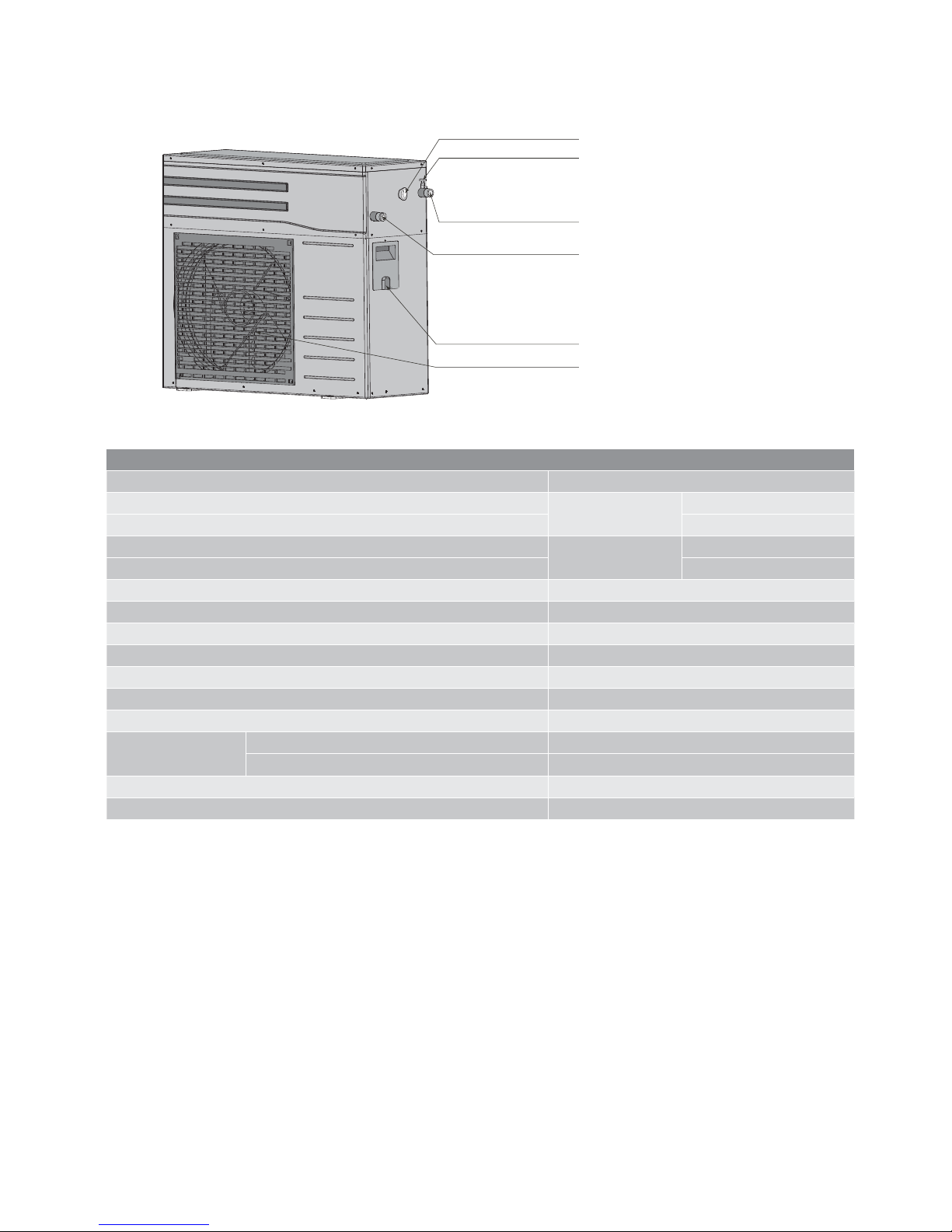
Heat pump specifications
KSE362HPCA Heat pump
Dimensions ( w x h x d) in mm 790 x 765 x 275
Heating capacity (kW)
Condition 1*
4.30
Standard power (kW) 1.25
Heating capacity (kW)
Condition 2*
4.70
Standard power (kW) 1.39
Heat pump circuit power rating (kW) 1.95
Maximum power rating including tank element operation (kW) 3.60
Power supply 220V-240V ~ 50 Hz
Refrigerant R410A (1200g)
Maximum water pressure (kPa) 850
Outdoor protec tion rating IP24
Circulating water inlet and outlet connections (mm) 20 (3/4")
Air side heat
exchanger
Fan motor power (kW) 0.08
Air outflow mode Air flow from rear
Net weight (kg) 62
Full weight (kg) 65
NOTE: Condition 1*: Outdoor ambient temperature is
DB/WB 7°C/ 6°C, water inlet temperature of the units is 30°C ,
water outlet temperature is 35°C.
For more specific heat pump dimensions and safe installation
distances refer to page 8 of this manual.
Condition 2*: Outdoor ambient temperature is DB/WB 20°C/
15°C, water inlet temperature of the units is 15°C , water outlet
temperature is 55°C.
auxiliary heater boost button
air bleed valve
circulating water outlet
power cable entry
air outlet mesh enclosure
circulating water inlet
Page 5
Kelvinator heat pump hot water system storage tank specifications 5
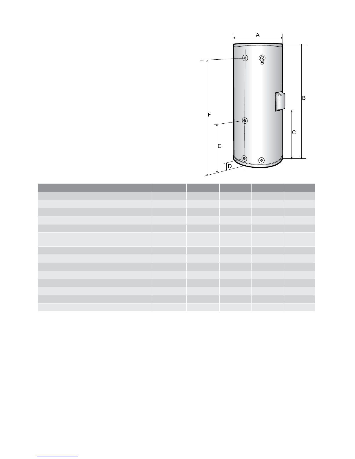
Storage tank specifications
Model number KCT27036A KCT27036B KCT34036A KCT34036B KC T42536B
Diameter (mm) - A 650 600 650 700 700
Height (mm) - B 139 0 1675 1690 1520 1785
Electrical connection height (mm) - C 580 750 680 700 850
Cold inlet and flow connection height (mm) - D 80 240 80 280 280
Return connection height (mm) - E 580 775 580 725 875
Hot outlet and relief valve connection
height (mm) - F
1165 1415 1475 1250 1515
Tank capacity (L) 270 270 340 340 425
Net weight (kg) 95 95 110 110 135
Tank wall thickness (mm) 2.5 2.5 3 3 3
Element rating (kW) 3.6 3.6 3.6 3.6 3.6
T/P relief valve pressure limit (kPa) 850 850 850 850 850
T/P relief valve temperature limit (°C) 99 99 99 99 99
T/P relief valve energy release rate (kW) 10 10 10 10 10
Full weight (kg) 365 365 450 450 560
Page 6

6 components Kelvinator heat pump hot water system
Components
Supplied with tank: KCT27036A, KCT27036B, KCT34036A, KCT34036B, KCT42536B
Item No. Quantity Image Description
1 1 of
KCT27036A - 270L tank with 3.6kW element
KCT27036B - 270L tank with 3.6kW element
KCT34036A - 340L tank with 3.6kW element
KCT34036B - 340L tank with 3.6kW element
KCT42536B - 425L tank with 3.6kW element
2 1
Bush 3/4" Male to 1/2" Female
3 1
Temperature and Pressure relief valve 1/2" Male
NOTE: The item numbers used in the table refer to the
numbers used in the installation diagram located in the
middle of this manual (pages 12 and 13)
Page 7

Kelvinator heat pump hot water system components 7
Components
Supplied with Heat Pump: KSE362HPCA
Item No. Quantity Image Description
4 1
KSE362HPCA - Heat Pump module
5 1
Sensor wire 6m
6 1
Sensor pocket assembly
7 4
Rubber mounting feet
8 1
Rubber seal for drain spigot
9 1
Drain spigot
Supplied with Heat Pump connection kit: KSEHPK A
11 3
Nipple 3/4" to 3/4" male
12 1
Tee piece 3/4" female
13 4
Elbow 3/4" male to 3/4" female
14 2
Flexible hose 1m 3/4" female, with fibre sealing washers
15 1
High performance tempering valve 50°C
NOTE: The item numbers used in the table refer to the
numbers used in the installation diagram located in the
middle of this manual (pages 12 and 13)
Page 8

8 installation Kelvinator heat pump hot water system
Installation of the heat pump hot water system shall be
completed in accordance with the AS/NZS 3500.1 and AS/
NZS 3500.4 plumbing codes regarding water and hot water
supply as well as local authority regulations and any other
applicable Australian standards.
If the heat pump hot water system cannot be installed
correctly to the Australian standards do not place it into
service. If any problems or questions arise during the
installation that cannot be answered in this installation
manual please call the relevant local authorities or the
Electrolux ser vice centre (number located in the warranty
section of this manual).
The heat pump has been charged with refrigerant and does not
require any on-site installation of refrigeration components.
Choosing a suitable installation location
The hot water storage tank can be installed either indoors or
outdoors however the heat pump must be installed outdoors
only. The heat pump is designed to operate within the
temperature range of -7°C to 50°C, ensure the site chosen is
within this ambient temperature range.
Please ensure the following:
1. Enough space for installation and maintenance is
available around the hot water system.
2. The height difference between the water outlet of the
heat pump and water inlet of the water tank will be less
than 5 metres.
3. The air inlet and outlet of the heat pump will be free from
obstacles and sheltered from strong winds.
4. The bearing surface is level, can bear the full weight of
the hot water system, and is suitable for installing the
heat pump without increasing noise or vibration.
5. The operational noise of the heat pump will not affect
occupants and neighbours.
6. No flammable items stored near the installation site.
7. The location is convenient for piping and wiring.
wall or obstacle
air inlet
air inlet
air outlet
A
B
D
fix with bolt
maintain channel
A
C
A B C D
300 600 1500 600
NOTE: All measurements are in mm.
caution
Installing the hot water system in any of the following places
may lead to malfunction of the system.
• Sites containing mineral oils such as cutting lubricant.
• Locations beside the sea where salt air can cause
corrosion.
• Locations near hot springs where corrosive gases exist,
e.g., sulfide gas.
• Factories where the supply voltage fluctuates markedly.
• Inside a cabin or caravan.
• Kitchens where oil permeates the air.
• Places where strong electromagnetic radiation exists.
• Places where flammable gases or materials exist.
• Places where acid or alkali gases evaporate.
If installing the heat pump in cyclonic areas or areas where
high levels of wind exist, ensure the mounting solution and
fixing is adequate. If possible, avoid installing the heat pump
at elevated heights in these areas and instead place it in a
more sheltered position at ground level.
E
A
D
C
B
H
12×22mm mounting hole
A B C D E H
563 295 100 790 275 765
NOTE: All measurements are in mm.
For specific dimensions of the storage tank and its
connections refer to page 5 of this manual.
Installation
Page 9

Kelvinator heat pump hot water system installation 9
Placing of heat pump and storage tank
The heat pump and storage tank must be installed on a level
surface and checked with a spirit level. The storage tank in
particular must be level to ensure the correct positioning
of the anode inside the tank and to prevent premature
breakage. Level installation will also ensure that hot water
is drawn from the top of the tank and will assist air being
dispelled during commissioning.
Heat pump placement and fixing
The heat pump may be installed mounted to a wall on a
bracket or on the ground. It must be fixed securely in place
and the rubber feet provided with the heat pump are to be
placed on the heat pump’s footings to dampen vibration.
Ensure that the mounting location is capable of handling
the full weight of the system and its components when filled
with water, refer specifications tables on pages 4 to 5 for full
weight details. If installing in a cyclone prone area, ensure
that the fixing methods are appropriate.
under heat pump:
drain assembly
(viewed from back
of unit)
Water may leak from the heat pump due to condensation
and this is part of normal operation. A drain elbow has been
provided with the heat pump and shall be installed, along
with a drain hose, if necessary. If the hot water system is
positioned where leakage could cause property damage,
install suitable drained safe-trays where appropriate.
Connections and piping of the hot water system
Connections on the heat pump and the storage tank are
all 3/4”.
Storage tank inlet connections
An isolating and non return valve must be installed on the
inlet to the hot water system. If the supply pressure may
exceed 600kPa, a pressure limiting valve must also be
installed on the inlet piping. A pressure relief valve may also
need to be installed on the inlet to the hot water system
under local plumbing requirements.
cold inlet
isolating
and non
return
valve
pressure
limiting
valve
(600kPa)
cold water
expansion
control valve
(700kPa)
inlet
flow
drain
Installation
Precautions before installing
1. Decide the correc t way to transport the hot water system.
2. Transport the hot water system in its original packaging
to avoid damage.
3. Ensure the heat pump is kept upright at all times,
including during transportation.
NOTE: Please confirm the mounting fixtures are strong enough
and mounted firmly if the heat pump unit is to be installed on
an external wall. If leakage of water from the hot water system
has potential to cause property damage, a properly drained safe
tray is to be installed under the heat pump and/or storage tank.
Frost protection
This hot water system can operate in frosty conditions down
to -7C when the following important installation requirements
are followed:
Ensure adequate insulation is installed on all exposed
connections, pipe work and hoses (minimum thickness 20mm).
The heat pump must be installed on continuous only power
supply so that power is available at all times in order for the
frost protection mechanism to operate.
The inlet valves and storage tank should be installed inside
if possible.
The relief valve piping must be installed in a frost free
environment in order to remain open to atmosphere at all times.
Electric heater tape is recommended to be installed
underneath piping insulation in extreme frost areas.
Water quality
Water quality can vary in different locations and affect the
performance and safe operation of the hot water system.
If the water supply is not within the acceptable limits as
indicated below, the hot water system should not be
installed, and may not be covered by the Electrolux warranty.
A suitable solution is to implement a water pre-treatment
process to bring the water quality to within acceptable limits
to support the installation.
The saturation index (SI) is a measure of the corrosive or
scaling properties of the water supply. Corrosive water (SI<-
1.0) can corrode copper components. In these conditions
warranty will not apply. Scaling water (SI>0.5) can cause
build up of CaCO3 (Calcium carbonate) which can impact
to the correct operation of moving parts within the system,
including the temperature and pressure relief valve. In these
conditions warranty may not apply.
Total Dissolved Solids (TDS) and water hardness can also
impact the life of the hot water system, and warranty does
not apply outside the following limits:
• TDS exceeding 600 p.p.m
• Electrical conductivity exceeding 850us/cm
• Total hardness exceeding 200 p.p.m
• Chloride exceeding 250 p.p.m
• Magnesium exceeding 10 p.p.m
• Sodium exceeding 150 p.p.m
• Acidity/Alkalinity must also be within the limits of
pH 6.5 - 8.5
If this hot water system is installed in a regional location
where regular flushing is required due to sediment build up,
then a drain cock for flushing must be fitted at the time of
installation. If in doubt, consult your plumber.
Page 10

10 installation Kelvinator heat pump hot water system
Heat pump connections
The heat pump can be installed up to 5 metres away from
the storage tank (only 1 meter of hose is supplied). If the
heat pump is to be installed further than 1m away, run hard
copper piping from the tank to a point near the heat pump.
Use the hoses supplied to connect from the heat pump to
the hard plumbing in order to dampen vibrations on the
circulating water piping from heat pump vibration. The
hoses and any additional piping between the heat pump and
storage tank must have 20mm thick insulation covering them
to maintain the efficiency of the system. The hoses supplied
in the heat pump connection kit KSEHPKA must be used and
old hoses are not to be re-used. Under no circumstances
should an isolation valve be installed on the hoses or
connections between the heat pump and the storage tank.
The circulating water inlet connection to the heat pump is to
be plumbed to the flow connection on the storage tank. The
circulating water outlet connection on the heat pump must
be plumbed to the return connection on the storage tank.
inlet
outlet
The 3/4" tee piece provided will need to be installed on the
storage tank’s return connection to allow the sensor pocket
to be installed and inserted into the storage tank along with
the heat pump outlet connection.
return
Storage tank outlet connections
This hot water system may deliver hot water between 47C to
60C during normal operation. Any pipes delivering hot water
to the premises are to be installed with sufficient piping
insulation to maintain the efficiency of the hot water system
and to prevent heat loss. It is recommended that a heat
trap be installed on the outlet piping of the storage tank to
minimize convective heat loss. The supplied tempering valve
must be installed in order to temper any water that travels to
fixtures primarily used for the purposes of personal hygiene
(e.g. bathroom or ensuite fixtures) down to 50°C as required
by AS/NZS 3500.4.
tempering
valve
outlet
uncontrolled
hot water outlet
(kitchen, laundry)
tempered (50°C)
hot water outlet
(bathrooms)
Relief valve piping
A 99°C/850kPa temperature and pressure relief valve comes
supplied with the storage tank and must be installed on
the relief valve connection near the top of the tank. The
drainage piping from the relief valve (and the one on the inlet
if installed) must have a constant downward fall and must
be plumbed to an outside drain. The outlet of the drainage
piping must be left open to the atmosphere at all times, and
installed in a frost free environment.
outlet
relief valve
Installation
Page 11

Kelvinator heat pump hot water system installation 11
Filling with water and dispelling air from the system
At this stage the wiring to the hot water system should either
be disconnected at the switchboard or have the power
isolated to it (off). Once all plumbing connections have been
made to the hot water system, it will need to be filled with
water and pressurized in order to check for leaks and to
dispel air from the system.
Activate the lever on the relief valve located on the
storage tank.
activation
lever
relief valve
outlet
Turn on the water supply to the premises and open the
isolation valve located on the inlet piping to the storage tank.
Water should begin flowing into the hot water system and
air will be dispelled from the relief valve piping. When water
begins flowing from the relief valve piping de-activate the
lever and wait for the hot water system to pressurise. Check
for any leaks in the hot water system and fix them as required.
Open the air bleed valve located on the circulating water
outlet connection of the heat pump. Wait until water is
flowing freely out of the air bleed valve and then close it. The
heat pump should now be primed with water.
inlet
outlet
air bleed
valve
Open the nearest hot tap or fixture to the hot water system.
Once water is flowing freely from the hot tap or fixture,
indicating that all air has been dispelled from the hot water
system, close the hot tap or fixture.
Installation
Page 12

12 installation diagram Kelvinator heat pump hot water system
Installation diagram
uncontrolled
hot wate r outlet
(kitchen, laundry)
refer to local electrical
requirements to
ascertain whether
isolat ion switch is
required
under heat pump (drain assembly
viewed f rom back of unit ) –
discharge condensation drain
hose to a su itable loca tion
tempered
(50°C)
hot water
outlet
(bathrooms)
tempering
valve
25mm
diameter
conduit
20mm
diameter
conduit
outlet
inlet
isolating
and non
return
valve
pressure limiting
valve (6 00kPa)
may be required
if pressure
exceeds 600kPa
cold water
expansion
control valve
(700 kPa) may be
required refer to
local plumbing
guidelines
cold
inlet
continuous
supply input
continuous
supply input
storage tank
heater output
150 mm
Ø2.5mm
storage tank
heater output
off pe ak
supply input
senso r cable plu gs in here
refer to th e electri cal secti on for more detai l
on wiri ng the heat pump
continuous wiring configuration off peak wiring configuration
All numbered items are supplied with the hot water sy stem. Please refer to the Component s list on pages
6 & 7 for details. Items which are not numbered are not supplied and need to be supplied by the installer in
accordance with loc al plum bing requirements. Inst allation of this hot water system mus t be completed by
an authorised and licensed person in accordance with all local regulations, including AS350 0 plumbing and
drainage requirements and AS300 0 elec trical wiring standards.
25mm
diameter
conduit
Page 13

Kelvinator heat pump hot water system installation diagram 13
relief valve
relief valve
outlet
drain
earth terminal
return
flow
flow
return
inlet
neutral terminal
wiring terminal
block
element
thermostat
earth
active terminal
conduit adaptor goe s in
here and l ocking ring
holds i t
Note: terminal block may differ
slightly d epending on mo del.
Page 14

14 electrical connection Kelvinator heat pump hot water system
Electrical wiring
The heat pump hot water system must be installed in
accordance with the AS/NZS 3000 wiring rules, the local
electrical authority regulations and any other applicable
standards. The pipe work, storage tank and heat pump are
to be properly connected to the earthing system of the
premises in accordance with AS/NZS 3000. The fixed wiring
must be protected by insulating sleeving with the appropriate
temperature rating and a means for disconnection must be
incorporated into the wiring.
The heat pump hot water system has the capability to be
wired on a standard continuous power supply or with an
additional off-peak supply if this is available at the premises.
The heat pump requires a continuous power supply in both
conditions in order to power the electronics that control the
heat pump, to ensure it has freeze protection and to allow
the auxiliary heating boost function to operate at any time
of the day. The continuous supply cable must be capable of
handling the current required to power the 3.6kW element in
the storage tank.
warning
In order to avoid a hazard due to inadvertent resetting of
the heat pump's protective cut-outs, the continuous supply
must not be supplied through an external switching device
such as a timer, or connected to a circuit that is regularly
switched on and off by the utility.
If an off-peak power supply is connected to the heat pump,
it will only operate its automatic heating function when the
off-peak power supply becomes available. The heat pump
has been designed to operate on extended off-peak which is
available up to 18 hours of the day compared to the standard
off-peak which is available only 8 hours. The off-peak power
supply cable must be capable of handling the current required
to operate the 1.95kW compressor circuit of the heat pump.
Note: Please refer to the AS/NZS 3008 standard for the current
carrying capacity of the cables to be used to ensure that they
are capable of handling the current draw of the heat pump in
the conditions that they are to be installed in.
When the cables are run externally, they are to be installed
in conduit in order to provide mechanical protection. The
recommended size of the conduit to the heat pump is 25mm
due to the number and size of the cables required to connec t
to the hot water system. A junction box or tee piece will need
to be installed in order for one conduit to go to the heat pump
and one to the storage tank. The storage tank has provision
for a 20mm conduit adapter and a 25mm to 20mm reducer
may need to be installed at the junction box or tee piece. It is
recommended that an isolator be installed that can disconnect
each power supply to the heat pump simultaneously, to assist
in maintenance and shut down of the hot water system, this
however, is not mandatory.
Depending on the wiring configuration, two or three cables will
be wired to the heat pump. The power supply cable(s) will be
run from the switchboard to the heat pump whilst the storage
tank heater cable will be run between the storage tank and the
heat pump. All cables will need to pass through a junction box,
tee piece or isolator in order to branch off to their separate
locations. If this heat pump hot water system is replacing an
existing electric hot water system, a power supply cable may
already be available for use. An additional active wire may need
to be run from the switchboard as required in order to give the
heat pump a continuous or an off-peak power supply.
For safety reasons it is recommended that the wiring of the
heat pump and storage tank be completed first before the
cables are wired to the switchboard. If you are replacing an
existing electric hot water system and re-using the existing
cable, ensure that the power supply to this cable is isolated or
disconnected at the switchboard.
Wiring the heat pump
All cables are to be passed through the cable clamp inside
the terminal box and the clamp securely fastened so that if
the conduit or cables are pulled, no stress is placed on the
terminal connections.
For safety reasons, all earths are to be connected first and
wired to the G terminal.
The continuous power supply input and the storage tank
heater output cables must both be capable of handling the
current draw of the 3.6kW element. The active wire of the
continuous supply input must be wired to the “HL” terminal
and the neutral wire to the HN terminal.
The active wire of the storage tank heater output cable is to be
wired to the L1 terminal and the neutral wire to the
N1 terminal.
Electrical connection
*
*
*
XP10
XS10
T5
XT2
red
red
blue
white
black
black
temp sensor
in water t ank
please connect with the
attached T5 temp. sensor
For installation on continuous only
phase, install jumper leads between
compressor supply input and
continuous supply input terminals
as per diagram.
N2 compressor circuit supply input 220 -240V~ 50Hz
L2 connect to off-peak or continuous supply
G common earth terminal
HN continuous supply in put
HL 220-240V~ 50Hz
N1
heater line output
L1
14 electrical connection Kelvinator heat pump hot water systems
Page 15

Kelvinator heat pump hot water system electrical connection 15
Electrical connection
Wiring the heat pump on a continuous power supply only:
If the heat pump is to be wired to a continuous power supply
only, the jumper leads supplied with the heat pump are to
be installed. The red jumper lead is to be wired between
terminals HL and L2. The black jumper lead is to be wired
between terminals HN and N2. This will provide power to
the compressor circuit of the heat pump and is shown in the
diagram below.
150 mm
Ø2.5mm
active (red)
neutral (black)
earth green/yellow
continuous
supply input
storage tank
heater output
Wiring the heat pump with an off-peak power supply:
If the heat pump is to be wired with an off peak power supply,
there are a number of ways that this can be achieved. The off
peak power supply active wire is always to be wired to terminal
L2, however the off peak power supply cable could be a single
active wire, or have a neutral and an earth wire. The neutral
wire, if available, would be wired to terminal N2 however in the
case of the having a single active wire, the black jumper lead will
need to be installed between terminals HN and N2. These two
off peak wiring configurations are shown in the diagram.
Off peak wiring configuration 1.
active (red)
neutral (black)
earth green/yellow
continuous
supply input
storage tank
heater output
off peak
supply input
Off peak wiring configuration 2.
active (red)
neutral (black)
earth green/yellow
continuous
supply input
storage tank
heater output
off peak
supply input
If the heat pump is replacing an electric hot water system
that has an off peak power supply cable, another alternative
is running a single active cable for the continuous power
supply from the switchboard. In this case the black jumper
lead will also be installed between terminals HN and N2 and
the wiring configuration will look similar to the “off-peak wiring
configuration 1" in the diagram. Since the continuous power
supply would be using the off-peak supply cable’s neutral, it
must be capable of handling the current drawn by the 3.6kW
heating element. If in doubt, run a cable from the switchboard
with an adequately sized active and a neutral.
Note: The two operating modes of the heat pump, Automatic
mode and Electric heating manual mode will never operate at
the same time. Therefore if you are using a shared neutral for
the continuous and off peak power supplies, the maximum
current flowing through the neutral will be achieved when the
heat pump is in Electric heating manual mode and powering
the 3.6kW element in the storage tank.
Page 16

16 electrical connection Kelvinator heat pump hot water systems
Wiring the hot water system to the switchboard:
The hot water system is required to be connec ted to the
earthing system of the premises and to the earth stake. Each
earth wire is to be wired to the earthing terminal inside the
switchboard. The active wire of each power supply to the heat
pump is required to be connected to an appropriately rated
and labelled circuit breaker and the circuit breakers must be
located next to each other. The neutral wires must
be connected to the unprotected neutral bar.
Electrical testing of the heat pump hot water system
Once the hot water system has been filled with water, the
following mandatory tests are required to be completed as per
the AS/NZS 3000 Australian Standards:
a) Continuity of the earthing system
b) Insulation resistance
c) Polarity
d) Correct circuit connections
e) Verification of impedance required for automatic
disconnection of supply
Note: The heat pump is required to be electrically
disconnected during the insulation resistance testing to
prevent damage to its electronics.
Refer to the AS/NZS 3000 Australian Standard for specific
details on how to perform these tests and the acceptable
readings that must be obtained. If the electrical installation
fails a test, that test and any preceding tests that may have
been influenced by the fault indicated shall be repeated after
the fault has been rec tified.
Heat pump fuse rating
There is a 5A 250V T5AL 20mm glass cylinder type fuse
located on the printed circuit board of the heat pump.
Wiring the hot water storage tank:
The 20mm conduit adapter is to be inserted into the 20mm
cut-out provided and the locking ring screwed down to hold
the conduit firmly in place.
The earth wire is to be wired to the earthing terminal on the
bottom left hand side of the terminal block. The active is to be
wired to terminal “A1” and the neutral to terminal “N” of the
wiring terminal block.
thermostat
element
wiring
terminal
block
neutral
terminal
active
terminal
earth
terminal
conduit adaptor
goes in here
and locking ring
holds it
earth
Electrical connection
Page 17

Kelvinator heat pump hot water system temperature sensor connection 17
Installing the temperature sensor in the storage tank
The copper end of the sensor cable is the temperature
sensing device and is to be installed in the sensor pocket
located at the “return” connection on the storage tank. When
inserting the sensor into the sensor pocket, ensure that it
is inserted all the way into the pocket and reaches the end.
Install the plug and fix the clamp to the sensor pocket using
the screws provided. This will prevent the temperature sensor
from being pulled out of the pocket and seals it from the
outside environment.
return
The heat pump requires feedback of the water temperature
inside the storage tank in order to determine when it needs
to operate. To achieve this the temperature sensor (supplied
with the heat pump) is required to be run between the heat
pump and the storage tank. It is recommended that the sensor
cable be neatly cable tied to the conduit or pipe work that
runs between the storage tank and heat pump. Any excess
cable should be neatly tied in a loop and kept out of the
way. However, if it is a possibility that the sensor cable could
become damaged during the life of the hot water system, it is
recommended that it be protected by installation in a conduit
or similar protective means.
Connecting the sensor cable at the heat pump
Inside the heat pump’s terminal box is a female plug socket
that the male plug end of the sensor cable plugs into. Push the
male plug into the female socket until it clicks into place.
Temperature sensor connection
Page 18

18 commissioning Kelvinator heat pump hot water system
3. Once the heat pump has stopped and the tank is up to
temperature, drain some water off using a hot tap inside
and then operate the auxiliary boost button. Monitor
and confirm the operation of the tank element and
thermostat.
4. Once the hot water system is up to temperature, check
that hot water is available to all hot taps or fixtures in the
house and there is sufficient flow or pressure. Ensure that
any fixtures designed primarily for purposes of personal
hygiene do not have hot water above 50°C coming from
them and adjust the tempering valve as necessary.
5. Clean any filters that are installed in the water system of
the premises or at the individual fixtures as they may have
become blocked by debris during the installation and
commissioning of the hot water system.
Now that commissioning has been completed and the heat
pump hot water system has been set up to operate correctly,
select the correct model number of the storage tank on page
5 of the user manual. Fill out your details, the serial numbers,
installation date and any important notes for the customer.
The user manual is then to be handed to the customer or
left in a suitable location on the premises. If the customer is
available they should be instructed on the safe and correc t
operation of the hot water system.
NOTE: If the heat pump hot water system needs to be
drained after commissioning please refer to the maintenance
section in the user manual supplied with the heat pump
for instructions.
Commissioning must only be commenced once the
installation has been completed according to the relevant
Australian standards and the instructions in this manual.
Confirm the following before operation:
• The heat pump has been installed correctly
• Air inlet and outlet of heat pump are free of obstacles
• Relief valve(s) installed correctly
• Drainage piping installed correctly
• Supplied tempering valve is installed correctly
• All water connections are correct
• Piping insulation has been installed
• Inlet valve is fully open
• Water is not leaking from the hot water system
• Air has been bled from the storage tank and
heat pump
• Temperature sensor installed correctly in
sensor pocket
• Electrical cables installed correctly
• Wiring configuration is correct
• Electrical testing has been completed and
satisfactory result obtained
• Power supply is either continuous or extended
off peak
The following steps are to be followed af ter the installation
of the heat pump hot water system to ensure its safety and
performance. If the hot water system cannot be setup to
perform correctly as specified in this manual, please call the
service centre for further instructions (number located in the
warranty section of this manual).
1. Turn on the power supply to the hot water system. If it has
been installed on an off peak power supply it may need
to be temporarily wired to a continuous power supply for
commissioning.
2. Allow the heat pump to run and monitor its operation
until the water in the storage tank reaches the set point
temperature and the heat pump shuts down. This may
take a few hours depending on the size of the storage
tank and the conditions at the time.
NOTE: If the heap pump does not begin operating after
a few minutes despite power being supplied to the heat
pump and the tank water being cold, the auxillary heating
boost button may have accidently been pressed during
commissioning or installation whilst the heat pump was
powered up. In this case, switch off the power supply
(both if connected to seperate continuous and off peak 2
power supply) for 2 minutes, then switch power back on
again to reset to normal heat pump operation. After a few
minutes the heat pump should start to operate.
To force the heat pump to operate, remove the lid on the
heat pump and carefully press and hold the two buttons
marked "force" and "query" on the printed circuit board.
The circulating pump should start and after one minute
the heat pump will begin to operate.
Commissioning
Page 19

Kelvinator heat pump hot water system warranty 19
This document sets out the terms and conditions of the product
warranties for Electrolux Appliances. It is an important document.
Please keep it with your proof of purchase documents in a safe place
for future reference should you require service for your Appliance.
1. In this warranty:
(a) ‘acceptable quality’ as referred to in clause 10 of this warranty has
the same meaning referred to in the ACL;
(b) ‘ACL’ means Schedule 2 to the Competition and Consumer
Act 2010;
(c) ‘Appliance’ means any Electrolux product purchased by you
accompanied by this document;
(d) ‘ASC’ means Electrolux authorised service centres;
(e) ‘Electrolux’ means Electrolux Home Products Pty Ltd of 163
O’Riordan Street, Mascot NSW 2020, ABN 51 004 762 341 in
respect of Appliances purchased in Australia and Electrolux (NZ)
Limited (collectively ‘Electrolux’) of 3-5 Niall Burgess Road, Mount
Wellington, in respect of Appliances purchased in New Zealand;
(f) ‘major failure’ as referred to in clause 10 of this warranty has the
same meaning referred to in the ACL and includes a situation when
an Appliance cannot be repaired or it is uneconomic for Electrolux, at
its discretion, to repair an Appliance during the Warranty Period;
(g) ‘Warranty Period’ means the Appliance is warranted against
manufacturing defects in Australia and in New Zealand for the period
of 1 year, following the date of original purchase of the Appliance.
Specic components are warranted against manufacturing defects
in Australia for the periods listed below if there is evidence provided
to Electrolux that the Appliance was installed by a licensed plumber;
and in New Zealand if there is evidence that the Appliance was
installed according to the Electrolux installation guidelines which can
be inspected on the Kelvinator website;
• Hot water tank - cylinder 5 years , labour 3 years, parts 1 year
• Continuous Gas
- Heat Exchanger – parts 10 years, labour 3 years
- all others components - parts 3 years, labour 3 years
• Heat Pump Refrigerant Sealed System - 2 years parts and labour
• Solar Collectors - parts 5 years, labour 3 years, 1 year for all
other parts (mounting and connection sets)
(h) ‘you’ means the purchaser of the Appliance not having purchased
the Appliance for re-sale, and ‘your’ has a corresponding meaning.
2. This warranty only applies to Appliances purchased and used in Australia
or New Zealand and used in normal domestic applications and is in
addition to (and does not exclude, restrict, or modify in any way) any
non-excludable statutory warranties in Australia or New Zealand.
3. During the Warranty Period Electrolux or its ASC will, at no extra charge
if your Appliance is readily accessible for service, without special
equipment and subject to these terms and conditions, repair or replace
any parts which it considers to be defective. Electrolux or its ASC may
use remanufactured parts to repair your Appliance. You agree that
any replaced Appliances or parts become the property of Electrolux.
This warranty does not apply to light globes, batteries, lters or similar
perishable parts.
4. Parts and Appliances not supplied by Electrolux are not covered by this
warranty.
5. To the extent permitted by law, you will bear the cost of transportation,
travel and delivery of the Appliance to and from Electrolux or its ASC. If
you reside outside of the service area, you will bear the cost of:
(a) travel of an authorised representative;
(b) transportation and delivery of the Appliance to and from Electrolux or
its ASC.
In all instances, unless the Appliance is transported by Electrolux or an
Electrolux authorised representative, the Appliance is transported at the
owner’s cost and risk while in transit to and from Electrolux or its ASC.
6. Proof of purchase is required before you can make a claim under this
warranty.
7. You may not make a claim under this warranty unless the defect claimed
is due to faulty or defective parts or workmanship. Electrolux is not liable
in the following situations (which are not exhaustive):
(a) the Appliance is damaged by:
(i) accident
(ii) misuse or abuse, including failure to properly maintain or service
(iii) normal wear and tear
(iv) power surges, electrical storm damage, excessive water pressure,
excessive inlet water temperature or incorrect power supply
(v) incomplete or improper installation
(vi) incorrect, improper or inappropriate operation
(vii) insect or vermin infestation
(viii) failure to comply with any additional instructions supplied with
the Appliance;
(ix) quality of water that is not in accordance with the “Water Quality”
guidelines in the installation instructions;
(b) the Appliance is modied without authority from Electrolux in writing;
(c) the Appliance’s serial number or warranty seal has been removed or
defaced;
(d) the Appliance was serviced or repaired by anyone other than
Electrolux, an authorised repairer or ASC.
8. This warranty, the contract to which it relates and the relationship
between you and Electrolux are governed by the law applicable where
the Appliance was purchased. Where the Appliance was purchased in
New Zealand for commercial purposes the Consumer Guarantee Act
does not apply.
9. To the extent permitted by law and subject to your non-excludable
statutory rights and warranties, Electrolux excludes all warranties and
liabilities (other than as contained in this document) including liability for
any loss or damage whether direct or indirect arising from your purchase,
use or non use of the Appliance.
10. For Appliances and services provided by Electrolux in Australia, the
Appliances come with a guarantee that cannot be excluded under the
ACL. You are entitled to a replacement or refund for a major failure and
for compensation for any other reasonably foreseeable loss or damage.
You are also entitled to have the Appliance repaired or replaced if the
Appliance fails to be of acceptable quality and the failure does not
amount to a major failure. The benets to you given by this warranty are
in addition to your other rights and remedies under a law in relation to
the Appliances or services to which the warranty relates.
11. At all times during the Warranty Period, Electrolux shall, at its discretion,
determine whether repair, replacement or refund will apply if an
Appliance has a valid warranty claim applicable to it.
12. For Appliances and services provided by Electrolux in New Zealand,
the Appliances come with a guarantee by Electrolux pursuant to the
provisions of the Consumer Guarantees Act, the Sale of Goods Act and
the Fair Trading Act.
13. To enquire about claiming under this warranty, please follow these steps:
(a) carefully check the operating instructions, user manual and the terms
of this warranty;
(b) have the model and serial number of the Appliance available;
(c) have the proof of purchase (e.g. an invoice) available;
(d) telephone the numbers shown below.
14. You accept that if you make a warranty claim, Electrolux and its ASC
may exchange information in relation to you to enable Electrolux to meet
its obligations under this warranty.
Warranty
FOR SALES IN AUSTRALIA AND NEW ZEALAND
APPLIANCE: HOT WATER SYSTEMS
Important Notice
Before calling for service, please ensure that the steps listed in clause 13 above have been followed.
FOR SERVICE
or to nd the address of your nearest
state service centre in Australia
PLEASE CALL 13 62 26
For the cost of a local call (Australia only)
SERVICE AUSTRALIA
ELECTROLUX HOME PRODUCTS
www.electrolux.com.au
FOR SPARE PARTS
or to nd the address of your nearest
state spare parts centre in Australia
PLEASE CALL 1300 666 019
For the cost of a local call (Australia only)
FOR SERVICE
or to nd the address of your nearest
authorised service centre in New Zealand
FREE CALL 0800 10 66 10
(New Zealand only)
SERVICE NEW ZEALAND
ELECTROLUX (NZ) Limited
www.electrolux.co.nz
FOR SPARE PARTS
or to nd the address of your nearest
state spare parts centre in New Zealand
FREE CALL 0800 10 66 20
(New Zealand only)
KHWS_Warr_Aug13
Page 20

P/No. KHWHPI/2
© 2015 Elec trolux Home P roduc ts Pty Ltd A BN 51 004 762 3 41
KMAN_KHWHPIM _Oct15
If you’d like further information about Kelvinator
appliances, please visit your retailer, phone or email
our Customer Care team or visit our website.
telephone: 13 62 26
email: hotwatersystems@electrolux.com.au
web: kelvinator.com.au
Kelvinator. We are part of the Electrolux family.
Share more of our thinking at electrolux.com.au
 Loading...