

Page 1
Solar Hot Water Systems
Installation Manual
Page 2
2 contents Kelvinator solar hot water systems
Congratulations and thank you for choosing our solar hot
water system. Before you install the hot water system, we
recommend that you read through the entire installation
manual, which provides instructions on the safe installation
of the hot water system.
To avoid the risks that are always present when you install
a hot water system, it is important that you read the safety
instructions carefully to ensure that the hot water system is
installed correctly and safely.
After unpacking the hot water system please check that it is
not damaged. If in doubt, do not install the hot water system
but contact your local Electrolux Customer Care Centre.
Meanings of symbols used in this manual are shown below:
warning
This symbol indicates information concerning your
personal safety
caution
This symbol indicates information on how to avoid
damaging the hot water system
environmental tips
This symbol indicates tips and information about
economical and ecological use of the hot water system
environmental tips
Information on disposal for users
• Most of the packing materials are recyclable.
Please dispose of those materials through your local
recycling depot or by placing them in appropriate
collection containers.
• If you wish to discard this hot water system or an old one
that has been replaced, please contact your local
authorities for the correct method of disposal.
warning
• Contact an authorised installer for installation of this
hot water system.
• Contact an authorised service technician for repair
or maintenance of this hot water system.
• If a power cord is to be replaced, replacement work
must be performed by authorised personnel only.
• Installation work must be performed in accordance
with the national standards by authorised personnel
only. Wrong connection can cause over heating or fire.
• This hot water system should be installed in accordance
with AS/NZS 3000 and your local electrical wiring rules.
Important safety instructions ........................................... 3
Specifications .................................................................... 4
General installation ........................................................... 6
General installation of solar collectors ............................. 8
Components list ................................................................ 9
Roof installation – flat panel collectors........................... 10
Installation diagram –
electric boosted flat panel collectors ............................ 12
Installation diagram –
gas boosted flat panel collectors ................................... 13
Roof installation – evacuated tube collectors ................. 14
Installation diagram –
electric boosted evacuated tube collectors .................. 17
Installation diagram –
gas boosted evacuated tube collectors ......................... 18
Installation – storage tank and solar controller .............. 19
Electrical installation ....................................................... 23
Commissioning ................................................................ 25
Troubleshooting .............................................................. 28
Notes ............................................................................... 29
Warranty .......................................................................... 31
Conditions of use
This appliance is intended to be used in household and
similar applications such as:
• staff kitchen areas in shops, ofces and other working
environments.
• farm houses.
• by clients in hotels, motels and other residential type
environments.
• bed and breakfast type environments
Congratulations Contents
Page 3

This Installation Manual has been prepared for qualied
installers of the hot water system. Please keep in a safe place for
future reference. Installation must be performed by a qualied
installer (for example, a licensed plumber or gas tter).
warning
For continued safety of this appliance it must be installed,
operated and maintained in accordance with the
manufacturers instructions.
For the installer
The installation must be done in accordance with the
information supplied in this Installation Manual.
For gas boosted installations, please refer to Warnings and
Cautions in the Gas Continuous Flow installation manual
supplied with the unit. All other relevant National, State or
Local regulations must also be conformed with and these
include (but are not limited to):
• Australian Standard AS3500.1 – Water Supply
• Australian Standard AS3500.4 – Hot Water Supply
• Australian Standard AS3000 – Electrical Installation
• Australian Gas Association Code AS5601 –
Gas Appliance Installation
• Local Water, Gas & Electrical Authority Regulations
Municipal Building Codes
Important safety instructions
Ensure the following safety instructions are read and
understood before commencing installation.
warning
If you do not follow these instructions exactly, a re or
explosion may result causing property damage, personal
injury or loss of life.
• This appliance is not intended for use by persons (including
children) with reduced physical, sensor y or mental
capabilities or lack of experience and knowledge, unless
they have been given supervision or instruction concerning
use of the appliance by a person responsible for their safety.
• Children should be supervised to ensure that they do not
play with the appliance.
• If the solar hot water system is gas boosted and you smell
gas or smoke coming from the system:
– Do not try to light the hot water system.
– Do not touch any electrical switch
– Do not use any phone in your building
– Isolate the power at the main switchboard
– Check and isolate the main gas valve
– Immediately call your gas supplier from a neighbour's
phone. Follow the gas supplier's instructions
– If you cannot reach the gas supplier, call the
re department
• The piping system of the solar circuit is to be electrically
connected in the lower part of the building according to
local standards. The connection of the solar system to
an existing or to be created lightning protection system
or potential equalization may be implemented only by
authorised specialists.
• If the solar hot water system is gas boosted, ensure there
is proper ventilation to avoid oxygen deciency.
• Ensure that any water drained during installation does
not cause damage to the building or property.
• Be sure that the hot water system is well earthed in
order to avoid electric shock.
• The solar hot and solar cold pipes between the hot water
storage tank and solar collectors MUST BE copper
and fully insulated with closed cell polymer insulation
or similar (minimum thickness of 20mm). Thicker insulation
may be required to comply with the requirements of
AS/NZS 3500.4. Plastic pipe MUST NOT be used, as it
will not withstand the temperature and pressure of the
water generated by the solar collectors under stagnation
conditions. The solar collectors can generate extremely
high water temperatures of up to 272°C. Plastic pipe can
not withstand these temperatures. Failure of plastic pipes
can lead to the release of high temperature water
and cause severe water damage and flooding.
• The insulation must be weatherproof and UV resistant if
exposed to sunlight.
• All compression ttings must use brass or copper olives.
• The collectors must be lled with water before the
protective cover is removed to prevent damage to the
hot water system and harm to the installer.
• Ensure that the roof has the load bearing capacity
to withstand the weight of installation, including the
installers and the full collectors.
• Installation must be carried out in accordance with
local Occupational Health and Safety laws.
• Ensure that appropriate safety measures are taken to
prevent objects falling from the roof during installation.
• The standard roof mounting kit for the collectors supplied
with this unit is NOT suitable for cyclone prone areas.
If you are installing in a cyclone prone area, please
consult your local building authority for advice regarding
appropriate mounting requirements.
• The minimum inlet water pressure must be 150kPa.
• If the hot water system supply pressure exceeds 600kPa, a
pressure limiting valve must be tted to limit the pressure
to 600kPa. A cold water 700kPa pressure relief valve may
also need to be installed in the water inlet to the storage
tank according to local regulations.
• A 99°C/850kPa temperature and pressure relief valve
(supplied) must be installed near the top of the storage tank.
• Ensure that the discharge pipes of the pressure relief
valves are left open to the atmosphere at all times.
• The pressure-relief devices are to be operated regularly to
remove lime deposits and to verify that they are not blocked.
• If a supply cord is damaged, it must be replaced by the
manufac turer, its service agent or qualied persons in
order to avoid a hazard.
• The operation of the thermal cut-out on the hot water
storage tank indicates a possibly dangerous situation
(electric boosted installations only). Do not reset the
thermal cut-out until the hot water system has been
serviced by a qualied person.
• Solar hot water systems with at panel type collectors
are not designed to be installed in heavy frost or high
altitude areas 400m above sea level.
• This hot water system delivers water above 50°C
and a tempering valve must be installed to limit the
temperature of hot water to sanitary xtures primarily
used for the purpose of personal hygiene as per the
AS 3500 requirements.
• The temperature settings for the hot water system are
factory pre-set to ensure optimum energy efciency
whilst providing Legionella bacteria protection. The
temperature settings are therefore not adjustable by
the customer or installer.
Important Important safety instructions
Kelvinator solar hot water systems impor tant safety instruc tions 3
Page 4

4 specications Kelvinator solar hot water systems
Specifications
Collector Flat panel (KCPF20A)
Collector dimensions per panel (mm) length 2002 x width 1025 x depth 80
Gross surface area 2.05m
2
Aperture surface 1.81m
2
Net weight 34.5kg
Operating positive pressure. max. 1000kPa
Stagnation maximum temperature 199 °C
Header pipe outer diameter 22mm
Collector frame material Aluminium
Absorber material 0.12mm copper n with TiNOx selective coating
Glazing 4mm low iron tempered patterned glass
Insulation material 40mm glass wool
Collector Evacuated tube (KCPE12A)
Number of evacuated tubes per collector panel 12
Collector dimensions (mm) length 1390 x width 1640 x depth 100
Gross surface area 2.28m
2
Aperture surface 2.0m
2
Collector capacity 1.6L
Net weight 37kg
Operating positive pressure. max. 1000kPa
Stagnation maximum temperature 272°C
Collector header pipe outer diameter 15.0 mm
Collector piping connections 1/2"
Collector frame material Anodised aluminium
Material selective absorber layer Aluminium nitrite
Page 5
Kelvinator solar hot water systems specications 5
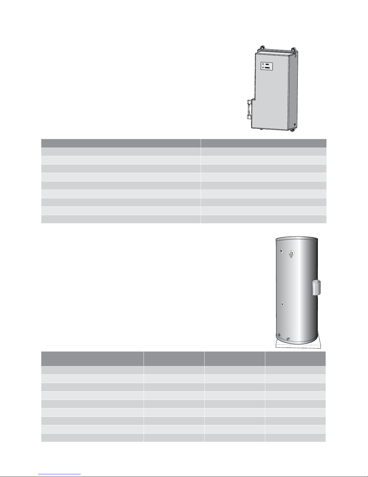
Specifications
Solar controller (KKSSUA)
Dimensions (mm) length 365mm x width 205mm x depth 100mm
Protection rating IPX4
Net weight 2.3kg
Operating positive pressure. max. 850kPa
Maximum water temperature 95°C
Circulation pump type UP15 – 14B
Circulation pump power 25W
Rated voltage of circulation pump AC 220-240V
Frequency 50Hz
Model number
KCT27000A
KCT27036A
KCT34000A
KCT34 036A
KC T4 5 036A
Diameter (mm) 648 648 730
Height (mm) 139 0 1690 1715
Tank capacity (L) 270 340 450
Net Weight (kg) 95 110 140
Tank wall thickness (mm) 2.5 3 3
Element rating (if installed) 3.6kW 3.6kW 3.6kW
PTR valve pressure limit (kPa) 850 850 850
PTR valve temperature limit (°C) 99 99 99
PTR max energy release rate (kW) 10 10 10
Page 6

6 gener al installation Kelvinator solar hot water systems
General installation
The collec tor rails, unions, straps, clamps, bolts, nuts and
washers required for the installation are included in the
collector kit(s). Suitable screws will be required to x the
collectors to the roof.
The collec tors and mounting kit are not designed to be
installed in cyclone prone areas. If installing in these areas or
other areas where a high level of windy and stormy conditions
exist, the collectors will need to be xed accordingly. Consult
the local authorities for advice regarding any additional
mounting instructions.
Use an appropriate amount of thread sealing tape or an
approved thread sealant in between all ttings.
Solar collector location
Consideration must be given to the position of the solar
collectors in relation to the hot water storage tank. The
maximum length of the solar hot and solar cold pipes must
be 10 metres one way (20 metres total) or less to full energy
efciency rating requirements.
• The solar collectors should be installed in a shade
free position.
• The solar collectors are to be installed facing toward
the equator (i.e. North). Where this orientation is not
practical, a system facing up to 45° from the equator will
have its efciency reduced by approximately 4%.
• Inclination of the solar collectors should be approximately
equal to 90% of the local latitude angle. Solar collectors
may be installed at the roof angle for simplicity of
installation and appearance, but must never be less than
10°. If the roof angle varies by 15° from the correct angle,
efciency will be reduced by 10%.
Latitudes of some Australian cities
Adelaide 35°S Port Hedland 20°S
Mildura 34°S Canberra 35°S
Brisbane 27°S Broken Hill 31°S
Darwin 12°S Geraldton 28°S
Rockhampton 24°S Cairns 17°S
Alice Springs 24°S Hobart 42°S
Melbourne 38°S Sydney 34°S
Townsville 19°S Perth 32°S
If the roof is flat or has a pitch less than or greater than the
recommended angle, a pitch stand may need to be installed
to allow the collectors to be mounted correctly. This stand
may need to be purchased from a local store or made
especially for the installation.
warning
PLUMBER BE AWARE!
• Water temperatures above 50°C can cause severe burns.
• All plumbing work must be carried out by a qualied
person and in accordance with the National Plumbing
Standard AS/NZS 3500.4 and local authority
requirements.
• Ensure the roof structure is suitable to carry the full
weight of the solar collectors. Each flat panel solar
collector and its ttings weigh approximately 45kg
when full of water. Each evacuated tube solar collector
and its ttings weigh approximately 47kg when full of
water. If in doubt the roof structure should be suitably
strengthened. Consult a structural engineer.
• Do not remove the solar collector packaging
completely, prior to the installation. Remove only
sufcient packaging material to enable the installation.
Upon completion of the installation it is necessary to
leave the solar collector packaging covering the glass
on the solar collector. The packaging should not be
removed until the solar hot water system has been
commissioned and is ready for use.
• Plastic pipe MUST NOT be used, as it will not withstand
the temperature and pressure of the water generated
by the solar collectors under stagnation conditions.
The solar collectors can generate extremely high
water temperatures up to 272°C. Plastic pipe cannot
withstand these temperatures and MUST NOT be used.
Failure of plastic pipe can lead to the release of high
temperature water and cause severe water damage
and flooding.
• There must be a continuous fall in the pipe work
between the solar collectors and the solar storage tank.
The highest point of the solar cold pipe and solar hot
pipe must be where they connect to the solar collectors,
to avoid the possibility of air locks occurring in the
system.
• Safety harnesses must be used when working at heights
and on the roof. If the roof is wet or dewy it will be very
slippery and installation work should not be carried out
until it has become dry.
The solar hot and solar cold pipes between the storage
tank and solar collectors MUST BE copper only and fully
insulated with closed cell polymer insulation or similar
(minimum thickness 20mm). Thicker insulation may be
required to comply with the requirements of AS/NZS 3500.4.
The insulation must be weatherproof and UV resistant. All
compression ttings must use brass or copper olives.
Note: Failure to observe this requirement may void the
warranty for freeze damage.
The insulation is essential to assist in providing freeze
protection. When installed on a metal roof, insulation will
ensure corrosion protection against water runoff over the
copper pipe, assist in avoiding accidental contact with the
pipe work and also reduce pipe heat loss.
Page 7

Kelvinator solar hot water systems general installation 7
General installation
Pipe lengths
The solar hot and solar cold pipes between the hot water
storage tank and the solar collectors must:
• have a continuous fall from the solar collectors to the hot
water storage tank of 5 (1 in 10 grade).
• not exceed the maximum recommended length of 10
meters (20 meters total).
Notes:
• It is important not to cross connect the solar cold and
solar hot pipes to the incorrect connec tions.
• In the at panel solar hot water system, the solar cold
pipes connect to the bottom of the solar collectors
and the solar hot pipe connects to the top of the solar
collectors diagonally opposite to the solar cold pipe
connection.
• In the evacuated tube hot water system, both connections
are located at the top of the collector.
• The collector sensor must be located in the same end as
the collector array outlet connection on both flat panel
and evacuated tube collectors.
It is essential for these requirements to be followed for the
system to operate correc tly and efciently. Solar pipe work that
is undersized, does not have the correct fall or is too long can
result in the solar hot water system not operating effectively.
Maximum height to collectors
The solar collectors must be the highest point of the system.
The maximum height of the solar installation, from the
base of the hot water storage tank to the top of the solar
collectors, is 9m. The pump supplied will not circulate closed
circuit uid through heights greater than 9m and solar gain
will not be achieved.
For heights greater than 9m, an auxiliary pump must be
installed above and within 1 m of the hot water storage tank.
Water quality
Water quality can vary in different locations and affect the
performance and safe operation of the hot water system.
If the water supply is not within the acceptable limits as
indicated below, the hot water system should not be
installed, and will not be covered by warranty from the
manufac turer. A suitable solution is to implement a water
pre-treatment process to bring the water quality to within
acceptable limits to support the installation.
The saturation index (SI) is a measure of the corrosive or
scaling properties of the water supply. Corrosive water (SI<-
1.0) can corrode copper components. In these conditions
warranty will not apply. Scaling water (SI>0.5) can cause
build up of CaCO3 (Calcium carbonate) which can impact
to the correct operation of moving parts within the system,
including the temperature and pressure relief valve. In these
conditions warranty will not apply.
Total Dissolved Solids (TDS) and water hardness can also
impact the life of the hot water system, and warranty does
not apply outside the following limits:
• TDS exceeding 600 p.p.m
• Electrical conductivity exceeding 850us/cm
• Total hardness exceeding 200 p.p.m
• Chloride exceeding 250 p.p.m
• Magnesium exceeding 10 p.p.m
• Sodium exceeding 150 p.p.m
• Acidity/Alkalinity must also be within the limits of
pH 6.5 - 8.5
Protecting the solar collectors
The solar collectors are designed to withstand impact and
be hail resistant, so it is not necessar y to install any special
hail guards to protect these collectors. However, if it is
possible that the collectors could be damaged due to falling
branches, vandalism etc. it is recommended that guards are
made and installed to prevent damage to the collectors.
Note: The installation of protective guards will impact on the
performance of the collectors.
Frost protection and damage due to freezing
The solar hot water system has been approved to level 2 frost
protection and can therefore withstand frosty conditions.
However, it is not recommended to install at panel type
collectors in areas 400m above sea level. It is recommended
that evacuated tube type collectors are installed in high altitude
and frost prone areas. The warranty for frost damage will not
apply if the hot water system is damaged due to freezing when
using flat panel type collectors in high altitude areas. The
warranty for frost damage will also not apply to solar hot water
systems with either type of collectors installed if the pipe work
between the collectors and the hot water storage tank has
insufcient piping insulation.
Page 8
8 gener al installation of solar collectors Kelvinator solar hot water systems
10 -15 mm
from horizontal
inlet
20-30mm
from horizontal
30-45mm
from horizontal
horizontal
collector rail
outlet
Note: The solar collectors (both flat panel and evacuated
tube) must be installed at an angle from the horizontal.
This is to ensure that any air in the system will travel to
the air vent valve located on the outlet connection of the
collectors.
The distance between the end of the collector rail at the
outlet side of the solar collectors and the horizontal must be:
10 - 15 mm (for one solar collector)
20 - 30 mm (for two solar collectors)
30 - 45 mm (for three solar collectors)
If the roof material is uneven where the collectors are to be
installed, then it may be necessary to add an additional 10
mm to the above distances for each collector.
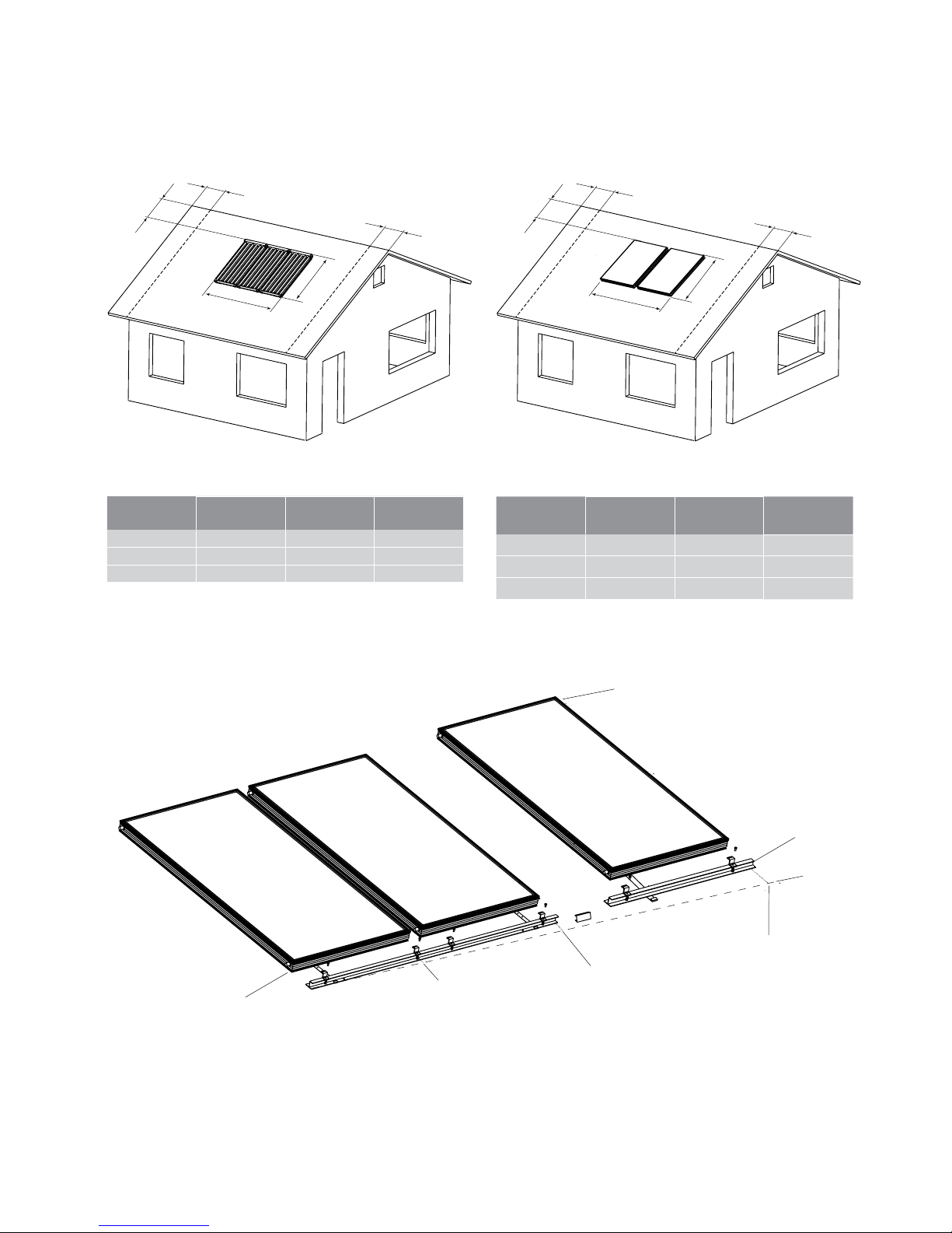
Space requirements
A
B
C
C
D
Space and load bearing requirements for evacuated
tube collectors
No. of
collectors
Dimension
A (mm)
Dimension
B (mm)
Weight when
full (approx.)
1 14 0 0 164 0 47kg
2 2800 1640 94kg
3 4200 1640 141kg
Dimensions C and D
• when determining the location for the collector ensure
that there is adequate space available for the water
connections and the xing of the mounting kit.
A
B
C
C
D
Space and load bearing requirements for flat
panel collectors
No. of
collectors
Dimension
A (mm)
Dimension
B (mm)
Weight when
full (approx.)
1 1025 2050 45kg
2 2050 2050 90kg
3 3075 2050 135kg
General installation of solar collectors
Page 9

components list Kelvinator solar hot water systems 9
Components list
Supplied in kit: KKSSF2MA –
flat panel double roof mounting kit
Item No. Qty. Description
1 1 rail bottom for 2x flat panel collector
2 2 strap rail bottom
3 4 clamp flat panel collector
4 4 bolt, nut and washer assembly
5 2 strap top flat panel collector
6 2 self tapping screw
7 2 connector flat panel collector
Supplied in kit: KKSSF1MA –
flat panel single roof mounting kit
Item No. Qty. Description
8 1 rail bottom for 1x at panel collector
9 1 rail joiner
2 2 strap rail bottom
3 2 clamp flat panel collector
4 2 bolt, nut and washer assembly
5 1 strap top flat panel collector
6 1 self tapping screw
7 2 connector flat panel collector
Supplied in kit: KKSSE1MA –
evacuated tube single roof mounting kit
Item No. Qty. Description
10 1 rail bottom for 1x evacuated tube
collector
2 2 strap rail bottom
11 2 clamp evacuated tube collector
4 2 bolt, nut and washer assembly
12 1 strap top left evacuated tube collector
13 1 strap top right evacuated tube collector
14 2 bracket top evacuated tube collector
6 2 self tapping screw
9 1 rail joiner
Supplied in kit: KCPF20A –
flat panel solar collector
Item No. Qty. Description
15 1 flat panel collector
Supplied in kit: KCPE12A –
evacuated tube solar collector
Item No. Qty. Description
16 1 evacuated tube collector
17 1 connector evacuated tube collector
18 2 connector sleeve support evacuated
tube collector
19 2 connector to 1/2" male for evacuated
tube collector
Supplied in kit: KKSSURA –
roof fittings kit
Item No. Qty. Description
20 2 connector to 1/2" male for at panel collector
21 2 stopper flat panel collec tor
22 2 union 1/2" female to copper
23 2 t-piece 1/2" female
24 2 nipple 1/2" to 1/2" male
25 1 bush 1/2" male to 3/8" female
26 1 air vent valve 3/8" male
27 1 sensor pocket 1/2" male
28 1 sensor collector with wire 15m
Supplied in kit: KKSSUGA –
ground fittings kit
Item No. Qty. Description
29 1 solar controller
30 4 screw xing solar controller
31 2 bush 3/4" male to 1/2" female
24 5 nipple 1/2" to 1/2" male
23 1 t-piece 1/2" Female
27 1 sensor pocket 1/2" male
32 1 exible tube 1/2" female to 1/2" female
33 1 check valve 1/2" male to 1/2" female
22 2 union 1/2" female to copper
34 1 tempering valve 50°C
Supplied with tank: KCT*****A –
tank and TP&R valve assembly
Item No. Qty. Description
35 1 temperature and pressure relief valve
1/2" male
31 1 bush 3/4" male to 1/2" female
36 1 of
KCT27036A -
270L tank with 3.6kW element
KCT34036A -
340L tank with 3.6kW element
KCT45036A -
450L tank with 3.6kW element
KCT27000A -
270L tank without element
KCT340 00A -
340L tank without element
Supplied with gas booster: KGC26S*A – gas booster
Item No. Qty. Description
37 4 screw gas booster xing
38 1 of
KGC26SNA -
26L/min solar gas booster - natural gas
KGC26SLA -
26L/min solar gas booster - LP gas
Page 10
10 roof installation – at panel collectors Kelvinator solar hot water systems
Roof installation –
flat panel collectors
Fix the bottom straps using appropriate screws into the
roof struts or trusses making sure the bottom rail is inclining
towards the proposed outlet end of the collectors.
If installing on a tiled roof, place the tiles back into their
normal positions after xing the straps.
Preparing and xing the collectors
Unpack each collector and cut out the template on the back
of the cardboard packaging. Place the cut out template
on the front of each collector and x it with tape. This is
important as the collector connections will become very
hot once exposed to solar radiation and may cause a safety
hazard or prevent the installation of the pipe work to the
collectors. Carefully lift the collectors onto the roof and
place them in position, resting against the bottom rail of the
collector mounting kit already xed to the roof.
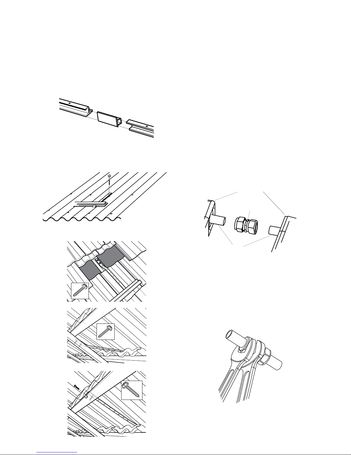
Before the collectors are xed to the roof and mounting kit, they
are to be connected together forming an array (two and three
collector installations only). Two compression union ttings are
used to join two collectors together (one for top and one for the
bottom) and are supplied in the mounting kit(s).
solar collectors
collector
manifold
pipes
compression
union
Slide the ttings onto one side of the collector manifold pipe
to be joined and then push both collec tors together. The
collector manifold pipes should be inserted as far as possible
into both sides of the compression union tting.
Using two spanners, tighten each nut on the compression
union tting one side at a time, with one spanner used to
brace the tting in the middle. Tighten both sides of the
compression union tting until the copper olives are rmly
sealed against both collector manifold pipes.
This standard roof mounting kit is not suitable for cyclone
prone regions. Refer to the warning in the Important Safety
Instructions section.
Unpack the collector mounting kit(s) and check that all
components are included (see mounting kit contents table).
If you are installing three collectors, join the two bottom rails
together using the rail joiner.
Slide the bottom straps onto the bottom rail so that they are
evenly spaced and place the bottom rail assembly on the roof
in the installation location decided. If installing on an iron roof,
line up the bottom straps to the existing roong screws that
are xing the iron roong membrane to the struts.
If installing on a tiled roof lift up the tiles and line up the
bottom straps with the roof struts or trusses.
Page 11

Kelvinator solar hot water systems roof installation – at panel collectors 11
Roof installation –
flat panel collectors
Collector pipe work connections
Open the ttings kit KKSSURA and check that all
components have been supplied (see components list).
Place two 1/2" male to collector compression union ttings
on the manifold pipes of the inlet and outlet of the collector
array (the inlet to the collector array will be at the bottom
and the outlet will be at the diagonally opposite corner at the
top). Tighten the nut using two spanners as before, sealing
the copper olive to the collector manifold pipes.
solar collector
1/2" male
to collecto r
compression union
collector
manifold
pipe
Place the stopper ttings from the kit onto the remaining
collector pipe work (also at diagonally opposite corners of
the collector array) and tighten as before with two spanners.
solar collector
stopper
collector
manifold
pipe
On the collector array outlet, install the two tee pieces, two
nipples, sensor pocket, 1/2" to 3/8" reducing bush, vent valve
and 1/2" female to copper union (see the diagram below).
Between the ttings use an appropriate thread sealant that
is capable of handling the high temperatures created by the
collectors. Ensure the vent valve is installed so that its vent is
pointing directly upwards, perpendicular to the ground (not
the roof).
vent valve
1/2" female to
copper union
sensor pocket
1/2" male to
collector union
1/2" to 3/8"
reducing bush
1/2"nipple
1/2"female T-piece
Once all the collectors are joined together (two or three
collector installations only), they should be correctly
positioned so that they are evenly distributed on the bottom
rail. Place the collector clamps on the bottom rail over the
top of the provided holes and inser t the bolts through the
holes in the clamps and bottom rail. Place the washers
and nuts on the bottom of the bolts and tighten with two
spanners, rmly clamping the collectors to the bottom rail.
If installing on an iron roof, line up a top strap with a
horizontal roof strut (look for where the iron has been xed)
and the top side of the collector. Fix the top strap to the roof
strut by either using an existing roong screw or adding a
new one.
If installing on a tiled roof, lift a tile above the collector and
line up a top strap with a roof strut or truss and the top side
of the collector. Fix the strap to the roof strut or truss and
place the tile back to its normal position (same procedure as
xing the bottom strap).
Fix the top strap to the top side of the collector using a
supplied self tapping screw and repeat for each additional
collector (two or three collector installations only).
Page 12

12 installation diagram – electric boosted at panel collector s Kelvinator solar hot water systems
Installation diagram - electric boosted flat panel collectors
Tiled roof – preferred method: Connect roof straps from bottom rail and top edge
of collectors to vertical roof beams. Secure with 2 screws at top of beams. Connect
roof straps from bottom rail and top of collectors to horizontal beams if vertical
beams are not accessible.
All num bered i tems are supplied with the ho t water s ystem. Pleas e refer to the Com ponents lis t for details. Items w hich ar e not num bered a re not su pplie d and
need to b e supplied by th e inst aller in accordance w ith local plu mbing r equir ement s. Installa tion of t his hot w ater sy stem must be c omple ted by an a uthorised and
licensed per son in accord ance wi th all local reg ulations, in cludi ng AS3500 p lumbi ng and dr ainage requi remen ts and A S3000 el ect rica l wirin g stan dard s.
Bottom rail connection viewed
from above
10 -15 mm
from horizontal
botto m rail
assembly
1.5m
relief valve
uncontrolled
hot water outlet
(kitchen, laundry)
tempered (50°C)
hot water outlet
(bathrooms)
tempering
valve
20-30mm
from horizontal
30-45mm
from horizontal
Connecting strap viewed from
roof cavity
Components shown in grey are only used in 2 and 3 collec tor panel connections
Secure with 2 straps on top and
back edge of beam
Iron roof: Connect bottom rail
and top edge of collectors to
iron roof.
securing top centre
of panel
isolating
and non
return
valve
pressure limiting
valve (600kPa)
may be required
if pressure
exceed s 600kPa
pressure relief
valve (700kPa)
may be required
refer to lo cal
plumbing
guidelines
drain
cold
inlet
flow
relief
valve
from
solar
return
horizontal
outlet
earth terminal
neutral terminal
wiring terminal
block
element
thermostat
active terminal
conduit adaptor
goes in he re and
locking ring holds it
Page 13

Kelvinator solar hot water systems installation diagram - gas boosted at panel collector s 13
Installation diagram - electric boosted flat panel collectors
Tiled roof – preferred method: Connect roof straps from bottom rail and top edge
of collectors to vertical roof beams. Secure with 2 screws at top of beams. Connect
roof straps from bottom rail and top of collectors to horizontal beams if vertical
beams are not accessible.
All num bered items a re supplied w ith the hot wate r system. Ple ase refer to the C omponent s list for det ails. Items wh ich are not num bered are not su pplied and ne ed to be
suppl ied by the inst aller in acco rdance with l ocal plumbi ng requireme nts. Installati on of this hot wat er system mu st be complet ed by an author ised and lice nsed perso n in
accordance wi th all local regul ation s, inclu ding AS 5601 ga s inst allati on requi remen ts, AS350 0 plumbi ng and dra inage re quire ment s a nd AS3 00 0 elec tric al wiring standards .
Bottom rail connection viewed
from above
10 -15 mm
from horizontal
botto m rail
assembly
relief valve
uncontrolled
hot water outlet
(kitchen, laundry)
tempered
(50°C)
hot water
outlet
(bathrooms)
tempering
valve
20-30mm
from horizontal
30-45mm
from horizontal
Connecting strap viewed from
roof cavity
Components shown in grey are only used in 2 and 3 collec tor panel connections
Secure with 2 straps on top and
back edge of beam
Iron roof: Connect bottom rail and
top edge of collectors to iron roof.
securing top centre
of panel
isolating
and non
return valve
pressure limiting
valve (600kPa) may be
required if pressure
exceed s 600kPa
pressure relief valve
(700 kPa) may be
required refer to
local plumbing
guidelines
drain
return
flow
inlet
cold
inlet
flow
relief
valve
from
solar
return
horizontal
outlet
1.5m
inlet
inlet
outlet
outlet
gas
gas
Page 14

14 roof installation – evacuated tube collectors Kelvinator solar hot water systems
Roof installation –
evacuated tube collectors
Fix the bottom straps into the roof struts or trusses using
appropriate screws, making sure the bottom rail is inclining
towards the proposed outlet end of the collectors.
If installing on a tiled roof, place the tiles back into their
normal positions after xing the straps.
Preparing and xing the collectors
Unpack each collector and check the contents against the
components list, being sure to leave the protec tive plastic
cover on each collector. This is important as the collec tor
connections will become very hot once exposed to solar
radiation and may cause a safety hazard or prevent the
installation of the pipe work to the collectors. Carefully lift
the collectors onto the roof and place them in position,
resting against the bottom rail of the collector mounting kit
already xed to the roof.
Before the collectors are xed to the roof and mounting kit,
they are to be connected together forming an array (two and
three collector installations only). The compression union
ttings supplied with the collectors are used to join the
collectors together.
Place the copper sleeve suppor ts into the manifold pipes
of each collector. Slide the ttings onto one side of the
manifold pipe to be joined and then push both collectors
together. The collector manifold pipes shall be inserted as far
as possible into both sides of the compression union tting.
solar collectors
copper sleeve
support
collector
manifold
pipes
compression
union
Using two spanners, tighten each nut on the compression
union tting one side at a time, with one spanner used to
brace the tting in the middle. Tighten both sides of the
compression union tting until the copper olives are rmly
sealed against both collector manifold pipes.
This standard roof mounting kit is not suitable for cyclone
prone regions. Refer to the warning in the Important Safety
Instructions section.
Preparing the mounting kit
Unpack the collector mounting kit(s) and check that all
components are included.
Slide the bottom straps onto the bottom rail and join the
bottom rails together using the rail joiner(s) if you are
installing two or three collectors.
Adjust the straps on the bottom rail so that they are evenly
spaced and place the bottom rail assembly on the roof in the
installation location decided. If installing on an iron roof, line
up the bottom straps to the existing roong screws that are
xing the iron roong membrane to the struts.
If installing on a tiled roof lift up the tiles and line up the
bottom straps with the roof struts or trusses.
Page 15

Kelvinator solar hot water systems roof installation – evacuated tube collectors 15
Once all of the collectors are joined together (two or
three collector installations only), they should be correctly
positioned so that they are evenly distributed on the bottom
rail. Place the collector clamps on the bottom rail over the
top of the provided holes and inser t the bolts through the
holes in the clamps and bottom rail. Place the washers
and nuts on the bottom of the bolts and tighten with two
spanners, rmly clamping the collectors to the bottom rail.
If installing on an iron roof, two top brackets supplied in the
mounting kit are to be used to x the collectors to the roof.
Line up the top brackets with a horizontal roof strut (look for
where the iron is xed) and the side of the collector array. Fix
the top brackets to the roof strut by either using an existing
roong screw or adding a new one.
Fix the top brackets to each side of the collector array with
the supplied self tapping screws.
If installing on a tiled roof, two twisted straps are to be xed
to the roof and each side of the collector array. The twisted
straps are to be xed so that the twisted ends are ush with
the sides of the collector array. It is important to determine
which strap is for the left hand side and which one is for the
right, before xing the strap to the roof. Lift the tiles above
each edge of the collector array and line up the appropriate
top twisted strap with a roof strut or truss and each side of
the collector array. Fix the flat end of the twisted strap to
the roof strut or truss and place the tile back to its normal
position. Fix the twisted end of the twisted strap to each side
of the collector array using the self tapping screws supplied
with the mounting kit.
Roof installation –
evacuated tube collectors
Page 16

16 roof inst allation – evac uated tube collectors Kelvinator solar hot water systems
Roof installation –
evacuated tube collectors
On the collector array inlet install a 1/2” to copper union
onto the 1/2” male compression union tting making sure to
use a thread sealant.
1/2" female to
copper union
1/2" male to
collector union
copper support
sleeve
Collector pipe work connections
Place the copper sleeve suppor t into the inlet and outlet
manifold pipes of the collector array. Install a 1/2" male
compression union tting (supplied with the collectors) and
tighten the nut using two spanners as before, sealing the
copper olive to the collector manifold pipes.
collector
1/2" male
compression
union
Open the ttings kit KKSSURA and check that all
components have been supplied (see components list). Since
this kit is also used for flat panel type collectors there will be
some pieces which will not be used.
On the collector array outlet install a tee piece, 1/2" to 3/8"
reducing bush, vent valve, 1/2" nipple and 1/2" female to
copper union (see diagram below). Between the ttings
use a thread sealant that is capable of handling the high
temperatures created by the collectors. Ensure the vent
valve is installed so that its vent is pointing directly upwards,
perpendicular to the ground (not the roof).
vent valve
T-p ie ce
1/2" female to
copper union
1/2" male to
collector union
1/2" to 3/8"
reducing bush
1/2"nipple
Page 17

Kelvinator solar hot water systems installation diagram – elec tric boosted evac uated tube collectors 17
Installation diagram – electric boosted evacuated tube collectors
Tiled roof – preferred method: Connect roof straps from bottom rail and
top edge of collectors to vertical roof beams. Secure with 2 screws at top
of beams. Connect roof straps from bottom rail and top of collectors to
horizontal beams if vertical beams are not accessible.
All num bered i tems are supplied with the ho t water s ystem. Pleas e refer to the Com ponents lis t for details. Items w hich ar e not num bered a re not su pplie d and
need to b e supplied by th e inst aller in accordance w ith local plu mbing r equir ement s. Installa tion of t his hot w ater sy stem must be c omple ted by an a uthorised and
licensed per son in accord ance wi th all local reg ulations, in cludi ng AS3500 p lumbi ng and dr ainage requi remen ts and A S3000 el ect rica l wirin g stan dard s.
Bottom rail connection viewed
from above
10 -15 mm
from horizontal
botto m rail
assembly
1.5m
relief valve
uncontrolled
hot water
outlet
(kitchen,
laundry)
tempered
(50°C) hot
water outlet
(bathrooms)
tempering
valve
20-30mm
from horizontal
30-45mm
from horizontal
Connecting strap viewed from
roof cavity
Components shown in grey are only used in 2 and 3 collec tor panel connections
Secure with screws on top
and back edge of beam
Iron roof: Connect bottom
rail and top edge of
collectors to iron roof.
Connecting top of
collectors to tiled
roof using twisted
metal straps.
isolating
and non
return
valve
pressure limiting
valve (600kPa)
may be required
if pressure
exceed s 600kPa
pressure relief
valve (700kPa)
may be required
refer to lo cal
plumbing
guidelines
drain
cold
inlet
flow
Ø20mm
conduit
relief
valve
from
solar
return
horizontal
insert sensor here then
apply s ilicone to seal .
Cable t ie the senso r
wire to ou tside of the
pipe insulation, ensuring
that th e wire does not
touch t he hot pipe.
outlet
earth terminal
earth
neutral terminal
wiring terminal
block
element
thermostat
active terminal
conduit adaptor
goes in he re and
locking ring holds it
1/2"nipple
Page 18

18 installation diagram – gas boosted evacuated tube collector s Kelvinator solar hot water systems
Installation diagram – gas boosted evacuated tube collectors
Tiled roof – preferred method: Connect roof straps from bottom rail and
top edge of collectors to vertical roof beams. Secure with 2 screws at top
of beams. Connect roof straps from bottom rail and top of collectors to
horizontal beams if vertical beams are not accessible.
All num bered items a re supplied w ith the hot wate r system. Ple ase refer to the C omponent s list for det ails. Items wh ich are not num bered are not su pplied and ne ed to be
suppl ied by the inst aller in acco rdance with l ocal plumbi ng requireme nts. Installati on of this hot wat er system mu st be complet ed by an author ised and lice nsed perso n in
accordance wi th all local regul ation s, inclu ding AS 5601 ga s inst allati on requi remen ts, AS350 0 plumbi ng and dra inage re quire ment s a nd AS3 00 0 elec tric al wiring standards .
Bottom rail connection viewed
from above
10 -15 mm
from horizontal
botto m rail
assembly
relief valve
uncontrolled
hot water outlet
(kitchen,
laundry)
tempered (50°C)
hot water outlet
(bathrooms)
tempering
valve
20-30mm
from horizontal
30-45mm
from horizontal
Connecting strap viewed from
roof cavity
Components shown in grey are only used in 2 and 3 collec tor panel connections
Secure with screws on top
and back edge of beam
Iron roof: Connect bottom
rail and top edge of
collectors to iron roof.
Connect top of
collectors to tiled
roof using twisted
metal straps.
isolating
and non
return valve
pressure limiting
valve (600kPa) may be
required if pressure
exceed s 600kPa
pressure relief valve
(700 kPa) may be
required refer to
local plumbing
guidelines
drain
return
flow
inlet
cold
inlet
flow
relief
valve
from
solar
return
horizontal
outlet
1.5m
inlet
inlet
outlet
outlet
gas
gas
insert sensor here then
apply s ilicone to seal .
Cable t ie the senso r
wire to ou tside of the
pipe insulation, ensuring
that th e wire does not
touch t he hot pipe.
Page 19

Installation – storage tank
and solar controller
Prepare the solar controller by installing a 1/2" nipple and
the flexible tube on the bottom connection of the solar
controller.
solar controller
connection
1/2" nipple
flexible tube
Place the solar controller in position above the “ow”
connection on the storage tank and line up the flexible
tube with the nipple on the “ow” connection. Fix the solar
controller to the storage tank using the screws provided. Do
not use any screws with a length longer than 13mm and if pre
drilling the holes is required, be very careful not to penetrate
too far into the storage tank. Use a spanner to connect the
exible tubing to the nipple of the “ow” connection of the
storage tank.
Install the check valve, nipple and 1/2” copper union to the
top of the solar controller with an appropriate thread sealant.
1/2" female to
copper union
1/2" nipple
check valve
solar controller
connection
Preparing the storage tank location
The storage tank shall be installed on a level surface,
preferably on a concrete platform so that it is elevated
slightly from the ground and has a uniform mounting surface
to spread its load. The storage tank shall be checked with a
spirit level to ensure it is level for a number of reasons:
• to ensure the correct positioning of the anode inside
the tank
• to ensure that any hot water is drawn from the very top
of the tank
• to assist air being dispelled during commissioning
Consideration should be given to any potential damage due
to water drainage or leakage. If leakage of water from the
hot water system has potential to cause property damage, a
properly drained safe tray is to be installed under the storage
tank. The relief valve drainage pipes will be required to be
plumbed to an outside drainage point.
Solar controller mounting and connections
Open the ttings kit KKSSUGA and check that all
components have been provided (refer to the components
list). It is recommended that the storage tank “ow”
connections be installed rst in order to determine the exact
location to mount the solar controller.
Install the tee piece, sensor pocket, 1/2" nipples and 3/4" to
1/2" reducing bush on the “ow” connec tion of the storage
tank using appropriate thread sealant (see diagram below).
FLOW
storage tank 'ow'
connection
sensor pocket
3/4" to 1/2"
reducing bush
T-p ie ce
1/2" nipple
Kelvinator solar hot water systems installation – storage tank and solar controller 19
Page 20

20 installation- storage tank and solar controller Kelvinator solar hot water systems
Installation – storage tank
and solar controller
20mm thermal
insulation around pipe
The storage tank “ow” connection is to be piped to the
inlet of the collector array. The outlet of the collector array is
to be piped to the “return” connection on the storage tank
and shall have continuous fall back to the storage tank. It
is recommended that the sensor cable be run at the same
time as the collector piping for convenience. Ensure that the
sensor cable is installed neatly, kept out of the way and is not
in contact with any potentially hot surfaces or copper piping.
If the tank is not to be installed until a later date, ensure that
the sensor plug is well protected and waterproofed (e.g. put in
plastic bag and cable tied in a safe location) until nal assembly.
Installation of storage tank inlet and outlet connections
Storage tank inlet connections
isolating
and non
return valve
pressure limiting
valve (60 0kPa)
may be req uired if
pressure exceeds
600 kPa
pressure relief
valve (70 0kPa) may
be required refer
to local plumbing
guidelines
cold
inlet
to storage
tank in let
An isolating and not return valve must be installed on the
inlet to the hot water system. If it is possible that the supply
pressure could exceed 600kPa, a pressure limiting valve shall
also be installed on the inlet piping. A pressure relief valve
may also need to be installed on the inlet to the hot water
system under local plumbing requirements.
If the hot water system is installed in a bad water quality
area where regular flushing is required due to sediment
build-up, a drain cock or valve is also to be installed on the
inlet piping.
On the storage tank return connection install a 1/2" copper
union, 1/2" nipple and 3/4" to 1/2" reducing bush with
appropriate thread sealant.
RETURN
storage tank return
connection
3/4" to 1/2"
reducing bush
1/2"
nipple
1/2"
nipple
Installation of pipe work between the collectors and
storage tank
The pipe work between the collectors and the hot water
storage tank is to be made of copper and be a minimum of
1/2" in diameter. It shall be covered with 20mm thick thermal
insulation to maintain the efciency of the system, prevent heat
loss and to allow the proper operation of the freeze protection.
Any piping insulation that will be exposed to sunlight must
also be UV resistant. The copper pipes shall be supported by
saddles and installed neatly with no sharp bends. The pipes
shall not exceed the recommended length of 10m (20m total)
and the height difference between the storage tank and the
collectors must not be greater than 9 meters. Penetrations
through the roong material must be neat, kept as small
as practical and made at the high point of the roof tile or
metal sheet. Exposed insulated pipe work between the solar
collectors and the penetration through the roong material
should be kept to a minimum to maintain the aesthetics of the
installation. The penetrations are to be waterproofed upon
installation of the pipe work and a boot shall be installed to
prevent any water from leaking into the premises.
Page 21

Storage tank outlet connections
It is recommended that a heat trap be installed on the outlet
piping of the storage tank in order to prevent convective
heat losses and to maintain the efciency of the hot water
system. If your system is gas boosted, the gas continuous
flow water heater supplied with the hot water system is to be
installed and connected to the hot water line after it leaves
the storage tank. Refer to the installation manual supplied
with the gas continuous ow water heater for specications,
dimensions, suitable installation locations and details on how
to install it.
Any pipes delivering hot water to the premises are to be
installed with sufcient piping insulation to maintain the
efciency of the hot water system and to prevent heat loss.
Any piping insulation that may be exposed to sunlight must
also be UV resistant. The tempering valve provided in the
KKSSUGA kit is to be installed in order to temper any water
owing to xtures primarily used for the purposes of personal
hygiene (e.g. bathroom or ensuite xtures). The water
supplying these xtures shall not exceed 50°C as required by
AS 3500.4.
heat trap
uncontrolled hot
water outlet –
kitchen, laundry
tempered hot water
outlet (50°C) –
bathrooms
tempering
valve
Relief valve piping
A temperature and pressure relief valve comes supplied with
the storage tank and must be installed on the relief valve
connection near the top of the tank.
stora ge tank relief
valve connection
temperature and
pressure relief valve
3/4" to 1/2"
reducing bush
RELIEF
VALV E
The drainage piping from the relief valve (and the one on
the inlet if installed) must have a constant downward fall
and must be plumbed to an outside drain. The outlet of
the drainage piping must be left open to the atmosphere at
all times, and installed in a frost free environment.
RELIEF
VALV E
OUTLET
drain
flow
inlet
warning
Failure to operate the relief valve easing gear at least
once every six months may result in the storage tank failing
or in extreme cases, exploding. Continuous leakage of
water from the valve may indicate a problem with the
hot water system.
Kelvinator solar hot water systems installation – storage tank and solar controller 21
Installation – storage tank
and solar controller
Page 22

22 installation – storage tank and solar controller Kelvinator solar hot water systems
Installation – storage tank
and solar controller
Connecting the temperature sensor at the storage tank
The short tank sensor from the solar controller goes inside
the sensor pocket located at the “ow” connection near
the bottom of the storage tank. When inserting the sensor
into the pocket, ensure that it is inserted all the way into the
pocket and reaches the end. Install the sensor pocket plug
and x the clamp to the sensor pocket using the screws
provided. This will prevent the temperature sensor from
being pulled out of the sensor pocket and seals it from the
outside environment.
FLOW
Filling the storage tank
Once all plumbing has been completed, it is necessar y to ll
the storage tank with water in order to allow the hot water
system to be electrically tested. Open the isolation valve on
the inlet piping and activate the temperature and pressure
relief valve on the tank.
drainage pipe
relief valve
activation
lever
Once water begins owing from the relief valve piping de-
activate the lever on the temperature and pressure relief
valve. Close the isolation valve on the inlet piping and repair
any leaks as necessary.
Installation - temperature sensor
The solar controller has two temperature sensors that
are required to be installed. One sensor will measure the
temperature of the water at the collector array. The other
sensor will measure the temperature of the water at the
bottom of the storage tank. Both temperature sensors
should not be run alongside power supply cables as this may
induce a false signal into the sensor cable.
Installing the collector array temperature sensor
The collec tor sensor cable is provided in the kit KKSSURA
and is 15m long. It has a temperature sensor on one end
that is required to be installed in the sensor pocket located
on the outlet to the collector array, and the connector at
the other end inserts into the plug at the solar controller.
It is recommended that this sensor cable be tied neatly to
the insulated pipe work between the storage tank and the
collector array. Any excess cable should be tied neatly in a
loop and kept out of the way. If it is possible that the sensor
cable could become damaged during the life of the hot
water system it is recommended that the sensor cable be
protected by installation in a conduit or by other protective
means. If the solar hot water system has evacuated tube
collector(s), the temperature sensor is to be installed in the
sensor pocket on the side of the collector near the outlet
pipe connections to the collector array. The sensor shall be
inserted all the way in and sealed with silicon to protect it
from the environment and hold it in place.
If the solar hot water system has at panel collector(s), the
temperature sensor is to be installed in the sensor pocket on
the outlet connection of the collector array. When inserting
the sensor into the pocket, ensure that it is inserted all the
way into the pocket and reaches the end. Install the sensor
pocket plug and x the clamp to the sensor pocket using the
screws provided. This will prevent the temperature sensor
from being pulled out of the sensor pocket and seals it from
the outside environment.
Page 23

Kelvinator solar hot water systems electrical installation 23
The current draw is approximately 0.1A for the solar controller
and 0.8A for the gas continuous ow water heater. If a new
power outlet is to be installed and wired to an existing power
circuit, consideration should be given to how many outlets
are already on the circuit and if the existing cable is capable
of handling the added current draw of the hot water system
or any other appliances that may potentially be plugged into
the new outlet. If a new cable supplying the outlet is to be
installed, it shall be protected by a suitably rated and labelled
circuit breaker. It is recommended that the outlet be used by
the hot water system only and not be shared with any other
appliances.
Electrical installation
The solar hot water system is required to be installed in
accordance with the AS/NZS 3000 wiring rules, the local
electrical authority regulations and any other applicable
standards. The pipe work, storage tank and collectors are to
be properly connec ted to the earthing system of the premises
in accordance with AS/NZS 3000.
Means for disconnection must be incorporated in the xed
wiring in accordance with the wiring rules. The insulation of the
xed wiring must be protected by insulating sleeving having
an appropriate temperature rating.
The solar controller and gas continuous flow water heater (if
system is gas boosted) require a weatherproof socket outlet
with a 240 volt alternating current continuous power supply.
This outlet shall be located as close as possible to the hot
water system, ideally within one and a half meters of the solar
controller and gas continuous ow water heater (if installed).
fuse 1
power supply pump
display unit
tank
sensor
collector
sensor
connector
CN1
up low collect
1
2
3
4
on
bw2
fre
ups
N L
3.15A/250VAC
Solar controller wiring diagram
Note: The solar controller contains a 3.15A 250V T3.15AL
20mm glass cylinder type fuse.
Page 24

24 electrical installation Kelvinator solar hot water systems
Electrical installation
If the solar hot water system is electric boosted, the storage
tank will have a heating element installed inside the tank. The
element is required to be installed with a 240 volt alternating
current continuous or off peak power supply. This heating
element is designed to be installed on extended off peak
which is available up to 18 hours of the day compared to the
standard off peak available only 8 hours. If the customer has
only standard off peak available, they should be advised to
call their electrical supplier and get it changed to extended
off peak. If the heater is connected to standard off peak and
not extended off peak power supply against manufacturers
recommendation, complaints from customers about
insufcient hot water being available will be considered an
installation fault and hence not covered under warranty. The
supply cable must be capable of handling the current draw of
the 3.6kW element and be protected by a suitably rated and
labelled circuit breaker. Where the cables are run externally,
they are to be installed in a conduit in order to provide
mechanical protection. The recommended size of the conduit
is 20mm and an entry has been provided for a 20mm conduit
adapter on the terminal box of the storage tank. If xing the
conduit to the storage tank with saddles be sure to use screws
no longer than 13mm in length and if pre drilling of holes is
required, be very careful not to penetrate too far into the
storage tank.
For safety reasons it is recommended that the wiring of the
storage tank be completed rst before the cable is wired to
the switchboard. If you are replacing an existing electric hot
water system and re-using the existing cable, ensure that the
power supply to this cable is isolated or disconnected at the
switchboard.
The 20mm conduit adapter is to be inser ted into the 20mm
cut-out provided and the locking ring screwed down to hold
the conduit rmly in place. The earth wire is to be wired to the
earthing terminal on the bottom left hand side of the terminal
block. The active wire is to be wired to terminal “A1” and the
neutral wire to terminal “N” of the wiring terminal block.
be very careful
not to penetrate
too far into the
storage tank
earth terminal
earth
neutral terminal
wiring terminal block
element
thermostat
active terminal
conduit adaptor goes
in here and locking
ring holds it
Electrical testing of the solar hot water system
Once the hot water system has been wired correctly and
the storage tank lled with water, the following mandatory
tests are required to be completed as per the AS/NZS 3000
Australian Standards:
a) Continuity of the ear thing system
b) Insulation resistance
c) Polarity
d) Correct circuit connections
e) Verication of impedance required for automatic
disconnection of supply
Note: The solar controller and gas continuous flow
water heater (if installed) are required to be electrically
disconnected during the insulation resistance testing to
prevent damage to their electronics.
Refer to the AS/NZS 3000 Australian Standard for specic
details on how to perform these tests and the acceptable
readings that must be obtained. If the electrical installation
fails a test, that test and any preceding tests that may have
been influenced by the fault indicated shall be repeated after
the fault has been rectied.
Page 25

Commissioning
Before commissioning the solar hot water system, please
conrm the following:
• Collector(s) have been installed correctly
• Collector(s) have been covered
• Collector array has been adequately xed to the roof
• Storage tank has been installed correctly
• Storage tank and collector array connections have
been completed
• The solar controller has been installed correctly
• Inlet piping and valves have been installed correctly
• Relief valve(s) have been installed and piped correctly
• Tempering valve has been installed correctly
• Piping between the storage tank and the collectors
has been installed correctly
• Gas continuous ow water heater has been installed
correctly (gas boosted only)
• Sufcient insulation has been installed on all hot
water piping
• The electrical supply is isolated to the hot
water system
• Electrical wiring has been completed and installed
correctly
• Electrical testing has been completed and
satisfactory results obtained
• Temperature sensors have been installed and
connected to the solar controller
The following steps are to be followed af ter the installation
of the solar hot water system to ensure its safety and
performance. If the hot water system cannot be setup to
perform correctly as specied in this manual, please call the
service centre for further instruc tions (number located in the
warranty section of this manual).
Filling the hot water system with water and checking
for leaks
At this stage, the power to the tank element and pump
station should be isolated (off). Fully open the cold water
isolation valve located on the inlet to the storage tank to
allow the system to begin lling with water.
Activate the temperature and pressure relief valve on the
storage tank in order to allow air to bleed out of the tank.
outlet
relief valve
activation
lever
drainage
pipe
Once water begins owing from the relief valve piping de-
activate the lever on the temperature and pressure relief
valve. The automatic air vent valve installed on the collector
array will allow air to bleed out of the solar hot water system.
Loosen the cap on the air vent valve to enable the air venting
function, then leave the cap loose after installation to allow
continued automatic air and steam venting as required. It
should not be necessary to manually bleed air from the top
of the collector (although it may take up to a few hours to
release all the air, depending on the installation). Check for
any water leaks on the storage tank, collector array and pipe
work connections, tightening or sealing as appropriate to
conrm the system is water tight.
In order to bleed air out of the hot water pipes into the
premises, open the nearest hot water tap or xture to the
hot water system.
Once water has begun owing freely from the hot water tap
or xture, indicating that all air has been expelled from the
hot water pipes, close the hot water tap or xture.
Kelvinator solar hot water systems commissioning 25
Page 26

Commissioning the solar controller
A solar monitor is located on the front of the solar controller
and houses a green and a red LED.
Remove the covering on the collector(s) to allow them to
begin receiving solar radiation and heating water in the
system. Plug in and switch on the power supply to the solar
controller. Once the electrical supply is switched on to the
solar controller it will start up and the green and red LED’s
will emit a constant glow for 2 seconds. If the solar hot water
system is operating correctly the green LED marked “solar”
will stay on and emit a constant glow.
SOLAR
ATTENTION
NOTE: The solar controller will monitor the temperatures
at the collector array and the storage tank in order to
determine the correct conditions to begin circulating the
water efficiently. As such it may not begin circulating water
immediately through the collector array.
If power to the solar controller is available and the green LED
is off or the red LED is ashing, this indicates that there may
be a fault with the hot water system. The red LED may emit
up to ve ashes every two seconds indicating the relevant
fault mode. See the chart below for descriptions of the
operating modes:
Flashes Operational modes
green & red constant glow power on initialization
green constant glow
(remains on)
standby mode, or circulating
water through collectors
Flashes Fault modes
4 x red
sensor in storage tank –
open circuit or short circuit
5 x red
sensor in collec tor – open
circuit or short circuit
red rapid flash
temperature difference
between collector and
storage tank higher than 40°C
for more than 10 minutes
during circulating
no green & red
(remains off)
power outage or call for service
If any of the fault modes occur, check that the temperature
sensors are installed correctly, connected to the solar
controller and that the cables have not been damaged. If
the red LED is emitting continuous ashes, this indicates
that water is not circulating through the collectors and the
storage tank correctly and that the temperature difference
between them has been greater than 40°C for ten minutes.
There may be air in the system that still needs to be bled
in order for the water to circulate correctly. Reset the solar
controller by cycling power to the controller at the power
outlet and bleed the air out of the collector array “ow” and
“return” lines.
Optimising circulating water flow through the
collector array
In order to optimise the energy per formance of the hot
water system, it is recommended to check and adjust the
circulating flow rate through the collector array. In order to
achieve this install an appropriate flow restrictor (control
valve or orice plate) and non intrusive ow sensor on the
piping to the collector array. It is recommended that the flow
sensor be installed at the outlet of the check valve connected
to the solar controller. The flow restrictor should be installed
at the outlet to the flow sensor.
The pump should start to circulate automatically if there
is sufcient sunlight, however if not, it may be necessary
to force circulation by articially warming the collector hot
sensor probe. This can be achieved by covering the probe
with a plastic cover and placing it in a cup of hot water
(please do not directly expose the sensor probe to water
ingress). Adjust the valve or ow restrictor until the circulating
flow rate registered on the flow sensor is as per the table
below, depending on the number of collectors installed in
the hot water system:
Number of collectors
installed:
1 2 3
Optimal circulating ow
rate (L/min):
1.0L /min 1.5L/min 2.0L/min
Commissioning
26 commissioning Kelvinator solar hot water systems
Page 27

Checking the hot water delivery temperature,
pressure and flow
Individually open each hot water tap or xture in the house
and check that hot water is available and that there is sufcient
ow or pressure. Ensure that any xtures designed primarily
for the purposes of personal hygiene (e.g. bathroom, ensuite)
do not supply hot water above 50°C and adjust the tempering
valve as necessary. If the hot water system is gas boosted,
check the installation manual supplied with the gas continuous
flow hot water heater to determine if it is operating correctly
and for any other specic commissioning instructions. Clean
any lters installed in the water system of the premises or at
the individual xtures as they may have been become blocked
by debris during the installation and commissioning of the hot
water system.
lter
Now that commissioning has been completed and the
solar hot water system has been setup to operate correctly,
select the specic components of the hot water system in
the user manual. Fill out your details, the serial numbers, the
installation date and any important notes to the customer.
The user manual (and the gas continuous flow user manual if
the system is gas boosted) is to be handed to the customer
or left in a suitable location on the premises. If the customer
is available, they are to be instructed on the safe and correct
operation of the hot water system.
If the flow sensor is to be removed after the optimal
circulating flow rate is set, close the isolation valve on the
inlet piping. Drain the water out of the system by activating
the relief valve. Remove the ow sensor from the circuit
and re-connect the collector array piping, leaving the ow
restrictor in place.
Open the isolation valve on the inlet piping and rell the
system with water, ensuring that all air is bled as per the
instructions provided. The solar hot water system is now
setup to run at the optimal circulation flow conditions in
order to gain the maximum energy savings.
Note: If enough circulating flow cannot be achieved it may be
necessary to reduce the number of bends in the pipe work
between the collectors and the storage tank or to increase
the diameter of the piping. An auxiliary pump may also need
to be installed.
Electric boosted solar hot water system
If the hot water system is electric boosted, turn on the power
supply to the storage tank element. If the element is wired
to an off peak tariff, it may need to be temporarily wired at
the switchboard to a continuous power supply in order to
heat the water for commissioning by a qualied electrician.
Wait until the water inside the storage tank is up to the
pre-set temperature of 60°C. This may take up to two hours
depending on the size of the storage tank, the temperature
of the supply water and the amount of hot water heated by
the collector array.
Gas boosted solar hot water system
If your hot water system is gas boosted, plug in and switch
on the power supply to the gas continuous flow hot water
heater. Open any gas or water isolation valves located on the
inlet to the gas continuous flow hot water heater.
Commissioning
Kelvinator solar hot water systems commissioning 27
Page 28

28 troubleshooting Kelvinator solar hot water systems
Troubleshooting
Problem Possible solutions
It takes a long time to get hot water
at the xtures
The time it takes to deliver hot water from your storage tank to your xtures
depends on the length and size of the piping between the two and also the
ow rate of the water to the xture. A longer distance, larger pipe diameter
or slower ow rate will all affect how long it takes hot water to reach your
xture, this is normal and not a product fault.
The water is cold or not hot enough
If a large amount of hot water has been used throughout the day, or the
system has been newly commissioned or drained, it may take some time
for the water temperature inside the tank to reach a normal level (electric
boosted only).
Check that power is available to the solar controller and the green LED
marked 'SOLAR' is lit.
Check that power is turned on to the storage tank element. If the tank
element is installed on an off- peak power supply, power may only be
available at certain times of the day (electric boosted).
Check that there is power and gas available to the gas continuous ow water
heater (gas boosted only).
Check there is enough ow coming from the xture to start the gas
continuous ow water heater (gas boosted only).
Check for cross plumbing between the cold water and hot water lines if there
has been new plumbing carried out recently.
If the tank element is installed on off peak, check with your power provider
that you are on extended off peak or off peak 2 tariff. This appliance is not
designed for installation on pure off peak or off peak 1.
The water is too hot
Check with a thermometer if the water temperature in the bathroom is
over 50°C, if so the tempering valve may have an incorrect setting or be
malfunctioning. Please call a service technician.
Water is discharging from the relief
valve drainage pipe
It’s normal for a small amount of water to discharge during heating to allow
for hot water expansion. However if the relief valve appears to be continually
leaking water, activate the relief valve lever once or twice and then check
to see if the leak stops. If the relief valve is still leaking this could indicate a
problem with your solar hot water system, please call a service technician
The solar controller red LED is ashing
Check that the temperature sensors are installed, undamaged and connected
to the solar controller.
The pipe work to and from the collectors may be blocked or have air inside it.
Cycle power to the solar controller and see if the LED's return to normal. If the
red LED begins to ash again, call a service technician.
The gas continuous flow water heater
appears to be malfunctioning
Please see the user manual supplied with the gas continuous ow water
heater for more specific troubleshooting solutions
Rumbling or hammering sound coming
from the hot water system
This happens when very hot water that has flashed into steam (under
stagnation conditions) comes into contact with cooler water and is part of
the normal operation of the hot water system and not a product fault.
Steam is coming from the vent valve
installed on the outlet of the collectors
Under no-load conditions the water in the collectors will not be circulating
and may ash into steam. This steam may vent off as part of the no-load
protection in order to avoid pressure building up inside the collectors. This is
part of the normal operation of the hot water system and not a product fault.
Page 29

Kelvinator solar hot water systems notes 29
Notes
Page 30

30 notes Kelvinator solar hot water systems
Notes
Page 31

Kelvinator solar hot water systems warranty 3 1
This document sets out the terms and conditions of the product
warranties for Electrolux Appliances. It is an important document.
Please keep it with your proof of purchase documents in a safe place
for future reference should you require service for your Appliance.
1. In this warranty
(a) ‘acceptable quality’ as referred to in clause 10 of this warranty has
the same meaning referred to in the ACL;
(b) ‘ACL’ means Trade Practices Amendment (Australian Consumer
Law) Act (No.2) 2010;
(c) ‘Appliance’ means any Electrolux product purchased by you
accompanied by this document;
(d) ‘ASC’ means Electrolux’ authorised serviced centres;
(e) ‘Electrolux’ means Electrolux Home Products Pty Ltd of 163
O’Riordan Street, Mascot, NSW 2020, ABN 51 004 762 341 in
respect of Appliances purchased in Australia and Electrolux (NZ)
Limited of 3-5 Niall Burgess Road, Mount Wellington, in respect of
Appliances purchased in New Zealand;
(f) ‘major failure’ as referred to in clause 10 of this warranty has the
same meaning referred to in the ACL and includes a situation when
an Appliance cannot be repaired or it is uneconomic for Electrolux, at
its discretion, to repair an Appliance during the Warranty Period;
(g) ‘Warranty Period’ means:
(i) where the Appliance is used for personal, domestic or household
use (i.e. normal single family use) as set out in the instruction
manual, the Appliance is warranted against manufacturing
defects in Australia and in New Zealand for the period of 1 year,
following the date of original purchase of the Appliance. Specic
components are warranted against manufacturing defects in
Australia for the periods listed below if there is evidence provided
to Electrolux that the Appliance was installed by a licensed
plumber; and in New Zealand if there is evidence that the
Appliance was installed according to the Electrolux installation
guidelines which can be inspected on the Kelvinator website;
• Hot water tank cylinders - parts 5 years , labour 3 years
• Continuous Gas
- Heat Exchanger – parts 10 years, labour 3 years
- all others components - parts 3 years, labour 3 years
• Heat Pump Refrigerant Sealed System - 2 years parts and labour
• Solar Collectors - parts 5 years, labour 3 years, 1 year for all
other parts (mounting and connection sets)
(ii) where the Appliance is used for commercial purposes (including
being used to directly assist a business or where the Appliance is
used in a multi-family communal or share type environment), the
Appliance will then be warranted against manufacturing defects
in Australia for 0 years and in New Zealand for 0 years, following
the date of original purchase of the Appliance.
(h) ‘you’ means the purchaser of the Appliance not having purchased
the Appliance for re-sale, and ‘your’ has a corresponding meaning.
2. This warranty only applies to Appliances purchased and used in Australia
or New Zealand and is in addition to (and does not exclude, restrict, or
modify in any way) any non-excludable statutory warranties in Australia
or New Zealand.
3. During the Warranty Period Electrolux or its ASC will, at no extra charge
if your Appliance is readily accessible for service, without special
equipment and subject to these terms and conditions, repair or replace
any parts which it considers to be defective. Electrolux or its ASC may
use remanufactured parts to repair your Appliance. You agree that
any replaced Appliances or parts become the property of Electrolux.
This warranty does not apply to light globes, batteries, lters or similar
perishable parts.
4. Parts and Appliances not supplied by Electrolux are not covered by this
warranty.
5. You will bear the cost of transportation, travel and delivery of the
Appliance to and from Electrolux or its ASC. If you reside outside of the
service area, you will bear the cost of:
(a) travel of an authorised representative;
(b) transportation and delivery of the Appliance to and from Electrolux or
its ASC,
In all instances, unless the Appliance is transported by Electrolux or an
Electrolux authorised representative, the Appliance is transported at the
owner’s cost and risk while in transit to and from Electrolux or its ASC.
6. Proof of purchase is required before you can make a claim under this
warranty.
7. You may not make a claim under this warranty unless the defect claimed
is due to faulty or defective parts or workmanship. Electrolux is not liable
in the following situations (which are not exhaustive):
(a) the Appliance is damaged by:
(i) accident
(ii) misuse or abuse, including failure to properly maintain or service
(iii) normal wear and tear
(iv) power surges, electrical storm damage, excessive water pressure,
excessive inlet water temperature or incorrect power supply
(v) incomplete or improper installation
(vi) incorrect, improper or inappropriate operation
(vii) insect or vermin infestation
(viii) failure to comply with any additional instructions supplied with
the Appliance;
(ix) quality of water that is not in accordance with the “Water Quality”
guidelines in the installation instructions;
(b) the Appliance is modied without authority from Electrolux in writing;
(c) the Appliance’s serial number or warranty seal has been removed or
defaced;
(d) the Appliance was serviced or repaired by anyone other than
Electrolux, an authorised repairer or ASC.
8. This warranty, the contract to which it relates and the relationship
between you and Electrolux are governed by the law applicable where
the Appliance was purchased. Where the Appliance was purchased in
New Zealand for business purposes the Consumer Guarantee Act does
not apply.
9. To the extent permitted by law, Electrolux excludes all warranties and
liabilities (other than as contained in this document) including liability for
any loss or damage whether direct or indirect arising from your purchase,
use or non use of the Appliance.
10. For Appliances and services provided by Electrolux in Australia, the
Appliances come with a guarantee that cannot be excluded under the
ACL. You are entitled to a replacement or refund for a major failure and
for compensation for any other reasonably foreseeable loss or damage.
You are also entitled to have the Appliance repaired or replaced if the
Appliance fails to be of acceptable quality and the failure does not
amount to a major failure. The benets to you given by this warranty are
in addition to your other rights and remedies under a law in relation to
the Appliances or services to which the warranty relates.
11. At all times during the Warranty Period, Electrolux shall, at its discretion,
determine whether repair, replacement or refund will apply if an
Appliance has a valid warranty claim applicable to it.
12. For Appliances and services provided by Electrolux in New Zealand,
the Appliances come with a guarantee by Electrolux pursuant to the
provisions of the Consumer Guarantees Act, the Sale of Goods Act and
the Fair Trading Act.
13. To enquire about claiming under this warranty, please follow these steps:
(a) carefully check the operating instructions, user manual and the terms
of this warranty;
(b) have the model and serial number of the Appliance available;
(c) have the proof of purchase (eg an invoice) available;
(d) telephone the numbers shown below.
14. You accept that if you make a warranty claim, Electrolux and its ASC
may exchange information in relation to you to enable Electrolux to meet
its obligations under this warranty.
Warranty
FOR SALES IN AUSTRALIA AND NEW ZEALAND
APPLIANCE: HOT WATER SYSTEMS
Important Notice
Before calling for service, please ensure that the steps listed in point 13 above have been followed.
FOR SERVICE
or to nd the address of your nearest
state service centre in Australia
PLEASE CALL 13 62 26
For the cost of a local call (Australia only)
SERVICE AUSTRALIA
ELECTROLUX HOME PRODUCTS
www.electrolux.com.au
FOR SPARE PARTS
or to nd the address of your nearest
state spare parts centre in Australia
PLEASE CALL 1300 666 019
For the cost of a local call (Australia only)
FOR SERVICE
or to nd the address of your nearest
authorised service centre in New Zealand
FREE CALL 0800 10 66 10
(New Zealand only)
SERVICE NEW ZEALAND
ELECTROLUX HOME PRODUCTS
www.electrolux.co.nz
FOR SPARE PARTS
or to nd the address of your nearest
state spare parts centre in New Zealand
FREE CALL 0800 10 66 20
(New Zealand only)
KHWS_Warr_Oct11
Page 32

P/No. KHWSGENI/1
© Copyr ight 2011 Electro lux Hom e Products P ty Ltd ABN 51 004 762 341
Print code: KM AN_ KHWSF UM_O ct11
If you’d like further information about Kelvinator
appliances, please visit your retailer, phone or email
our Customer Care team or visit our website.
telephone: 1300 363 640
fax: 1800 350 067
email: customercare@electrolux.com.au
web: www.kelvinator.com.au
Kelvinator. We are part of the Electrolux family.
Share more of our thinking at www.electrolux.com.au
 Loading...