

Page 1
SERVICE/INSTALL MANUAL
IMPORTANT INFORMATION,
KEEP FOR OPERATOR
USA & Canada, 866-738-1640
4003 Collins Lane, Louisville, KY 40245
www.kelvinatorcommercial.com
THIS MANUAL MUST BE RETAINED FOR FUTURE REFERENCE. READ,
UNDERSTAND AND FOLLOW THE INSTRUCTIONS AND WARNINGS
CONTAINED IN THIS MANUAL.
PART NUMBER HB_738371_9F73837100, REV. A (03/23)
REV. B (06/23)
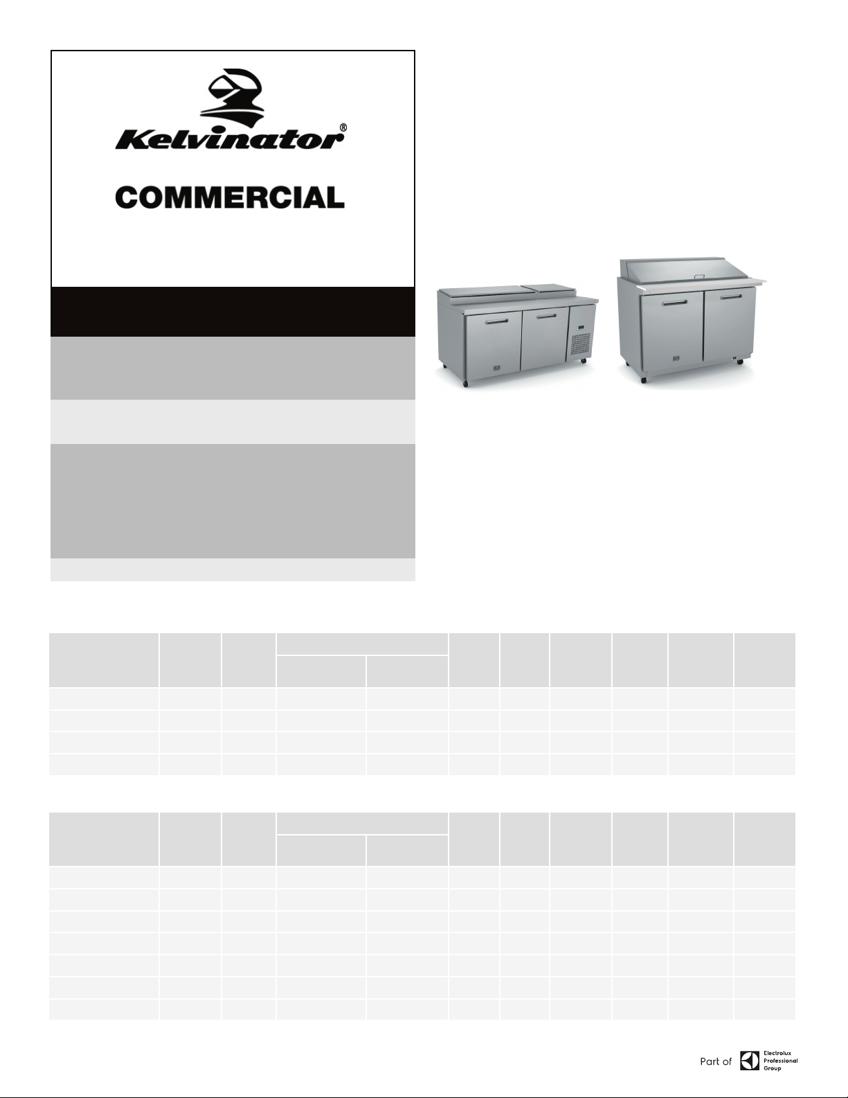
This manual provides information for:
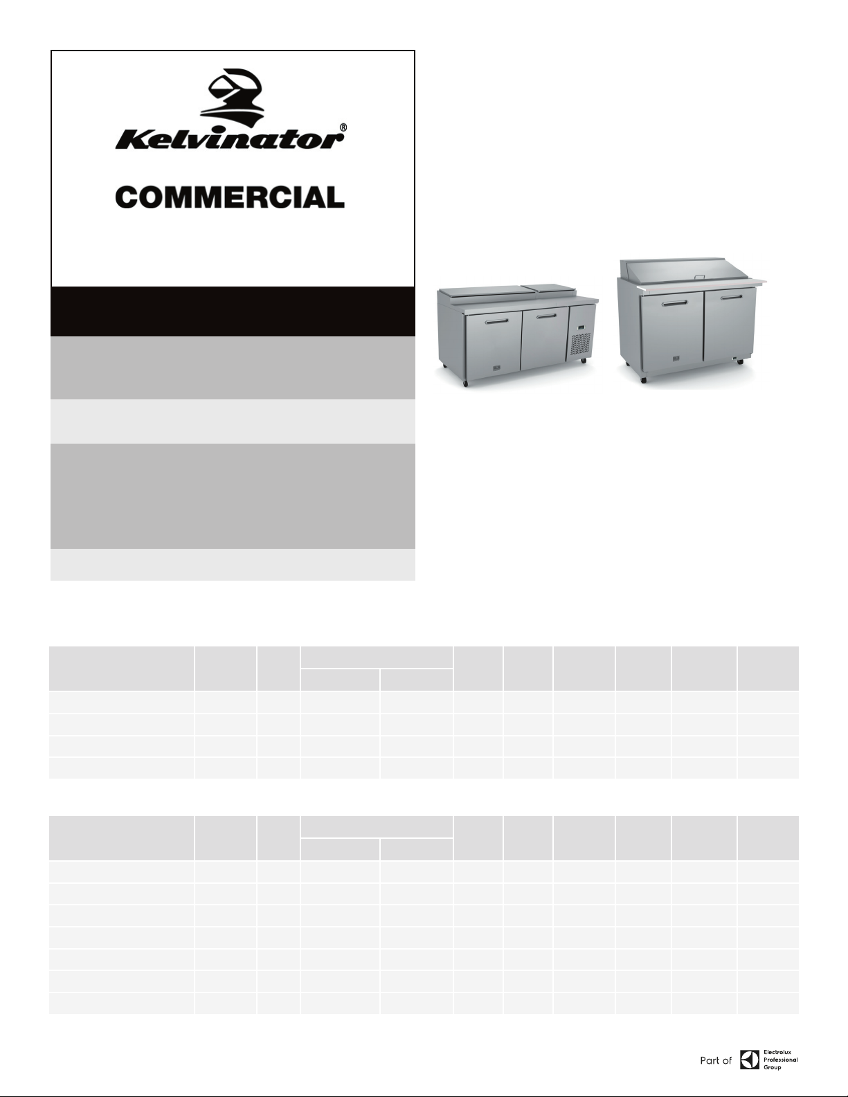
FOOD PREP TABLES
PIZZA PREP TABLES, SANDWICH/SALAD
UNITS, UNDER-COUNTER REFRIGERATORS AND
FREEZERS, WORKTOP REFRIGERATORS AND
FREEZERS
FOR YOUR SAFETY Do not store or use gasoline or other ammable vapors
and liquids in the vicinity of this or any other appliance.
NOTIFY CARRIER OF DAMAGE AT ONCE It is the responsibility of the consignee
to inspect the container upon receipt of same and to determine the possibility
of any damage, including concealed damage. Electrolux Professional, Inc.
suggests that if you are suspicious of damage to make a notation on the
delivery receipt. It will be the responsibility of the consignee to le a claim with
the carrier. We recommend that you do so at once.
Manufacture Service/Questions 866-738-1640.
RETAIN THIS MANUAL FOR FUTURE REFERENCE
NOTICE: Due to a continuous program of product improvement, Electrolux
Professional, Inc. reserves the right to make changes in design and specications
without prior notice.
installation. If certain recommended procedures are not followed, warranty claims
will be denied.
The serial number of all self-contained refrigerators and freezers is located inside
the unit on the left hand side near the top on the wall. Always have the serial
number of your unit available when calling for parts or service. This manual
covers standard units only. If you have a custom unit, consult the customer service
department at the number listed in this manual.
NOTICE: Please read the entire manual carefully before
EQUIPMENT DESCRIPTION
SANDWICH/SALAD UNITS
MODEL NO. V/HZ/PH AMPS
CAPACITY
STORAGE (CU FT) SHELF (SQ FT)
KCHST27.8 115/60/1 3.0 7 14 8 1/3 853 3.0 276 5-15P
KCHST48.12 115/60/1 4.3 12 26 12 1/2 1365 3.17 313 5-15P
KCHST60.16 115/60/1 4.3 15.5 30 16 1/2 1365 3.17 362 5-15P
KCHST70.18 115/60/1 4.3 18 36 18 1/2 1365 3.17 408 5-15P
MEGATOP SANDWICH/SALAD UNITS
CAPACITY
MODEL NO. V/HZ/PH AMPS
STORAGE (CU FT) SHELF (SQ FT)
KCHMT29.12 115/60/1 3.0 7 14 12 3/8 853 3.0 276 5-15P
KCHMT29.12.2D 115/60/1 3.0 7 - 12 3/8 853 3.0 276 5-15P
KCHMT48.18 115/60/1 4.3 12 26 18 1/2 1365 3.17 313 5-15P
KCHMT48.18.2D 115/60/1 4.3 12 13 18 1/2 1365 3.17 313 5-15P
KCHMT60.24 115/60/1 4.3 15.5 30 24 1/2 1365 3.17 362 5-15P
KCHMT60.24.2D 115/60/1 4.3 15.5 15 24 1/2 1365 3.17 362 5-15P
KCHMT70.30 115/60/1 4.3 18 36 18 1/2 1365 3.17 408 5-15P
PAN 1/6
SIZE
PAN 1/6
SIZE
HP BTU
HP BTU
CHARGE OZSHIP WEIGHT
LBS
CHARGE OZSHIP WEIGHT
LBS
NEMA PLUG
NEMA PLUG
Information contained in this document is known to be current and accurate at the time of printing/creation. Reference our product line website for the most updated product information and
specications. © 2023 Electrolux Professional, Inc. All Rights Reserved.
Page 2
IMPORTANT - READ FIRST - IMPORTANT
YOUR SAFETY AND THE SAFETY OF OTHERS ARE VERY IMPORTANT.
WE HAVE PROVIDED MANY IMPORTANT SAFETY MESSAGES IN THIS MANUAL AND ON YOUR
APPLIANCE. ALWAYS READ AND OBEY ALL SAFETY MESSAGES.
OUR PRODUCT INSTRUCTIONS WILL BE UPLOADED ON OUR COMPANY OFFICIAL WEBSITE.
THIS IS THE SAFETY ALERT SYMBOL. THIS SYMBOL ALERTS YOU TO POTENTIAL
HAZARDS THAT CAN KILL OR INJURE YOU AND OTHERS. ALL SAFETY MESSAGES
WILL FOLLOW THE SAFETY ALERT SYMBOL AND EITHER THE WORDS” DANGER”,
“WARNING” OR “CAUTION”.
DANGER MEANS THAT FAILURE TO HEED THIS SAFETY STATEMENT MAY RESULT
IN SEVERE PERSONAL INJURY OR DEATH.
WARNING MEANS THAT FAILURE TO HEED THIS SAFETY STATEMENT MAY
RESULT IN EXTENSIVE PRODUCT DAMAGE, SERIOUS PERSONAL INJURY, OR
DEATH.
CAUTION MEANS THAT FAILURE TO HEED THIS SAFETY STATEMENT MAY RESULT
IN MINOR OR MODERATE PERSONAL INJURY, OR PROPERTY OR EQUIPMENT
DAMAGE.
ALL SAFETY MESSAGES WILL ALERT YOU TO WHAT THE POTENTIAL HAZARD IS, TELL YOU
HOW TO REDUCE THE CHANCE OF INJURY, AND LET YOU KNOW WHAT CAN HAPPEN IF THE
INSTRUCTIONS ARE NOT FOLLOWED.
FOLLOW BASIC PRECAUTIONS, INCLUDING THE FOLLOWING:
NOTE: IF THE SUPPLY CORD IS DAMAGED, IT MUST BE REPLACED BY THE
MANUFACTURER, ITS SERVICE AGENT OR SIMILARLY QUALIFIED PERSONS IN
ORDER TO AVOID A HAZARD.
NOTE: THIS APPLIANCE IS NOT INTENDED FOR USE BY PERSONS (INCLUDING
CHILDREN) WITH REDUCED PHYSICAL, SENSORY OR MENTAL CAPABILITIES,
OR LACK OF EXPERIENCE AND KNOWLEDGE, UNLESS THEY HAVE BEEN GIVEN
SUPERVISION OR INSTRUCTION CONCERNING USE OF THE APPLIANCE BY A
PERSON RESPONSIBLE FOR THEIR SAFETY.
NOTE: CHILDREN SHOULD BE SUPERVISED TO ENSURE THAT THEY DO NOT PLAY WITH
THE APPLIANCE.
NOTE: THIS APPLIANCE CAN BE USED BY CHILDREN AGED FROM 8 YEARS AND ABOVE
AND PERSONS WITH REDUCED PHYSICAL SENSORY OR MENTAL CAPABILITIES
OR LACK OF EXPERIENCE AND KNOWLEDGE IF THEY HAVE BEEN GIVEN
SUPERVISION OR INSTRUCTION CONCERNING USE OF THE APPLIANCE IN A SAFE
WAY AND UNDERSTAND THE HAZARDS INVOLVED. CHILDREN SHALL NOT PLAY
WITH THE APPLIANCE. CLEANING AND USER MAINTENANCE SHALL NOT BE
MADE BY CHILDREN WITHOUT SUPERVISION.
NOTE: KEEP THE APPLIANCE AND ITS CORD OUT OF REACH OF CHILDREN LESS THAN 8
YEARS.
NOTE: DO NOT STORE EXPLOSIVE SUBSTANCES SUCH AS AEROSOL CANS WITH A
FLAMMABLE PROPELLANT IN THIS APPLIANCE.
NOTE: THE APPLIANCE USE FLAMMABLE INSULATION BLOWING GAS C5H10, DISPOSAL
OF THE APPLIANCE SHALL IN ACCORDANCE WITH THE REGULATIONS OF LOCAL
AUTHORITIES.
NOTE: THE KEY FOR APPLIANCE ELECTRIC BOX SHOULD BE SAFE KEPT BY QUALIFIED
PERSONS IN ORDER TO AVOID A HAZARD
WARNING: KEEP VENTILATION OPENINGS, IN THE APPLIANCE ENCLOSURE OR IN THE BUILT-IN
STRUCTURE, CLEAR OF OBSTRUCTION.
WARNING: DO NOT USE MECHANICAL DEVICES OR OTHER MEANS TO ACCELERATE
THE DEFROSTING PROCESS, OTHER THAN THOSE RECOMMENDED BY THE
MANUFACTURER.
WARNING: DO NOT DAMAGE THE REFRIGERANT CIRCUIT.
WARNING: DO NOT USE ELECTRICAL APPLIANCES INSIDE THE FOOD STORAGE COMPARTMENTS
OF THE APPLIANCE, UNLESS THEY ARE OF THE TYPE RECOMMENDED BY THE
MANUFACTURER. HANDLING, MOVING, AND USE OF THE REFRIGERATOR OR
FREEZER TO AVOID EITHER DAMAGING THE REFRIGERANT TUBING, OR INCREASING
THE RISK OF A LEAK.
CAUTION: RISK OF FIRE OR EXPLOSION DUE TO FLAMMABLE REFRIGERANT USED. FOLLOW
HANDLING INSTRUCTIONS CAREFULLY IN COMPLIANCE WITH U.S. GOVERNMENT
REGULATIONS. COMPONENT PARTS SHALL BE REPLACED WITH LIKE COMPONENTS
AND THAT SERVICING SHALL BE DONE BY FACTORY AUTHORIZED SERVICE
PERSONNEL, SO AS TO MINIMIZE THE RISK OF POSSIBLE IGNITION DUE TO
INCORRECT PARTS OR IMPROPER SERVICE.
CAUTION: RISK OF FIRE OR EXPLOSION DUE TO PUNCTURE OF REFRIGERANT TUBING; FOLLOW
HANDLING INSTRUCTIONS CAREFULLY. FLAMMABLE REFRIGERANT USED
DANGER: RISK OF CHILD ENTRAPMENT. BEFORE YOU THROW AWAY YOUR OLD REFRIGERATOR
OR FREEZER: TAKE OFF THE DOORS, LEAVE THE SHELVES IN PLACE SO THAT
CHILDREN MAY NOT EASILY CLIMB INSIDE.
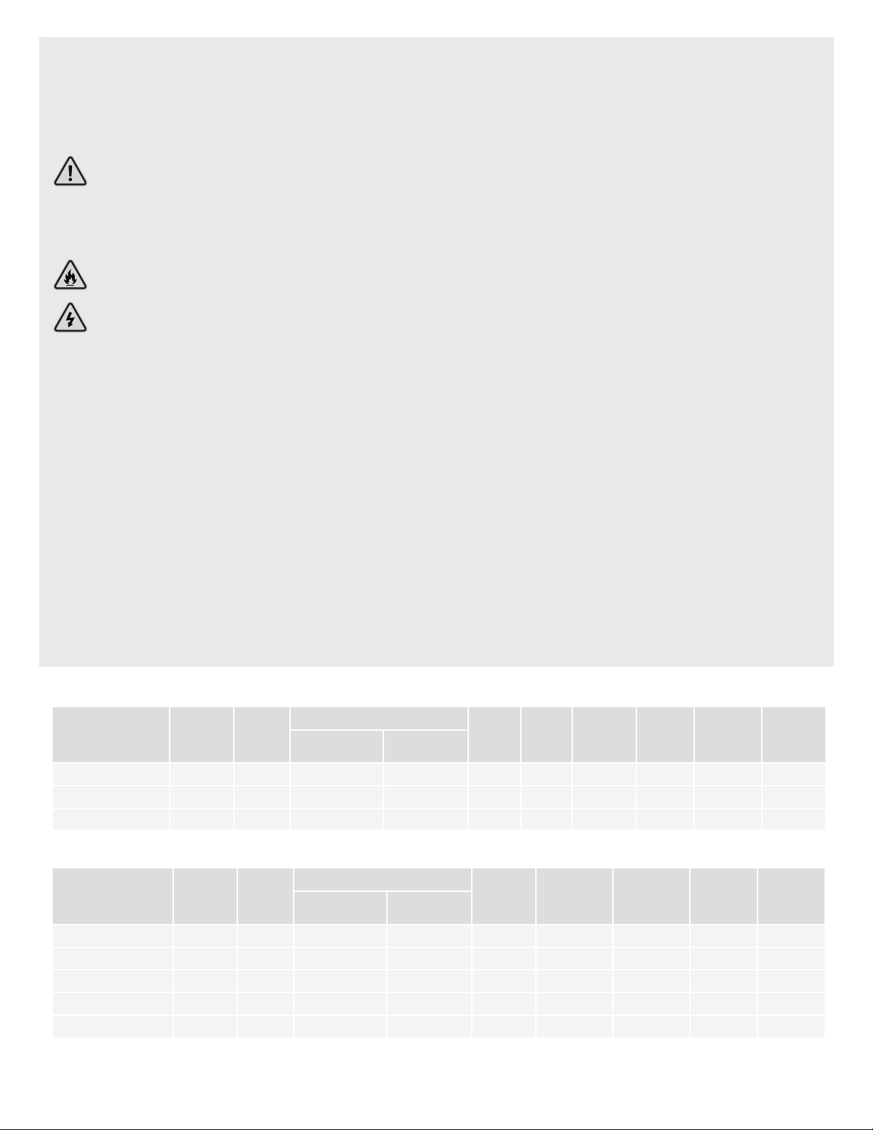
PIZZA PREP TABLES
MODEL NO. V/HZ/PH AMPS
CAPACITY
STORAGE (CU FT) SHELF (SQ FT)
KCHPT50.6 115/60/1 5.0 12 16 6 1/2 1365 3.7 348 5-15P
KCHPT60.9 115/60/1 5.0 22 34 9 1/2 1365 3.7 432 5-15P
KCHPT70.12 115/60/1 5.5 32 54 12 3/4 1877 3.7 582 5-15P
PAN 1/3
SIZE
HP BTU
CHARGE OZSHIP WEIGHT
LBS
NEMA PLUG
UNDER-COUNTER & WORKTOP REFRIGERATORS
MODEL NO. V/HZ/PH AMPS
STORAGE (CU FT) SHELF (SQ FT)
KCHUC27R/KCHUCWT27R 115/60/1 1.5 6.5 14 3/8 426 2.47 243 5-15P
KCHUC27.2DR 115/60/1 1.5 6.5 - 3/8 426 2.47 243 5-15P
KCHUC48R/KCHUCWT48R 115/60/1 3 12 26 3/8 478 2.65 300 5-15P
KCHUC60R/KCHUCWT60R 115/60/1 3 15.5 30 3/8 478 2.82 348 5-15P
KCHUC72R/KCHUCWT72R 115/60/1 3.5 18 36 3/8 853 4.59 380 5-15P
CAPACITY
HP BTU CHARGE OZ
SHIP WEIGHT
LBS
NEMA PLUG
2 FOOD PREP TABLES
Page 3

UNDER-COUNTER & WORKTOP FREEZERS
MODEL NO. V/HZ/PH AMPS
STORAGE (CU FT) SHELF (SQ FT)
KCHUC27F 115/60/1 1.9 6.5 14 1/2 1160 3.35 291 5-15P
KCHUC48F 115/60/1 2.4 12 26 1/2 1877 3.53 340 5-15P
KCHUCWT27F 115/60/1 1.9 6.5 14 1/2 1160 3.35 291 5-15P
KCHUCWT48F 115/60/1 2.4 12 26 1/2 1877 3.53 340 5-15P
CAPACITY
HP BTU CHARGE OZ
SHIP WEIGHT
LBS
NEMA PLUG
RECEIVING & INSPECTING THE EQUIPMENT
Even though most equipment is shipped crated, care should be taken during
unloading so the equipment is not damaged while being moved into the building.
1. Visually inspect the exterior of the package and skid or container. Any
damage should be noted and reported to the delivering carrier immediately.
2. If damaged, open and inspect the contents with the carrier.
3. In the event that the exterior is not damaged, yet upon opening, there is
concealed damage to the equipment, notify the carrier. Notication should
be made verbally as well as in written form.
4. Request an inspection by the shipping company of the damaged equipment.
This should be done within 10 days from receipt of the equipment.
5. Be certain to check the compressor compartment housing and visually
inspect the refrigeration package. Be sure lines are secure and base is still
intact.
6. Freight carriers can supply the necessary damage forms upon request.
7. Retain all crating material until an inspection has been made or waived.
INSTALLATION
NOTE:
DANGER:
LOCATION
Units represented in this manual are intended for indoor use only. Be sure the
location chosen has a oor strong enough to support the total weight of the
cabinet and contents. A fully loaded unit can weigh as much as 1500 pounds.
Reinforce the oor as necessary to provide for maximum loading. For the most
efcient refrigeration, be sure to provide good air circulation inside and out.
INSIDE CABINET
Do not pack the units so full that air cannot circulate. The refrigerated air is
discharged at the top rear of the unit. It is important to allow for proper air ow
from the top rear to the bottom of the unit. Obstructions to this air ow can cause
evaporator coil freeze ups and loss of temperature or overow of water from the
evaporator drain pan. The shelves have a rear turn up on them to prevent this.
However, bags and other items can still be located to the far rear of the cabinet.
Air is brought into the evaporator coil with fans. Prevent obstruction to allow the
outlet or inlet of air ow.
OUTSIDE CABINET
Be sure that the unit has access to ample air. Avoid hot corners and locations
near stoves and ovens. It is recommended that the unit be installed no closer
than 2” from any wall.
UNIT REPAIRS WILL NOT BE SUBJECT TO STANDARD UNIT WARRANTIES IF
DUE TO IMPROPER INSTALLATION PROCEDURES.
THE UNIT MUST BE TURNED OFF AND DISCONNECTED FROM THE POWER
SOURCE WHENEVER PERFORMING SERVICE, MAINTENANCE FUNCTIONS OR
CLEANING THE REFRIGERATED AREA.
LEVELING
A level cabinet looks better and will perform better because the doors will line
up with the frames properly. Use a level to make sure the unit is level from front
to back and side to side. Units supplied with legs will have adjustable bullet
feet to make the necessary adjustments. If the unit is supplied with casters,
no adjustments are available. Ensure the oor where the unit is to be located
is level.
STABILIZING
All models are supplied with casters for your convenience. It is very important,
however, that the cabinet be installed in a stable condition with the front wheels
locked while in use. Should it become necessary to lay the unit on its side or
back for any reason, allow at least 24 hours before start-up to allow compressor
oil to ow back to place. Failure to meet this requirement can cause compressor
failure and unit damage.
ELECTRICAL CONNECTION
Refer to the amperage data on page 5, the serial tag, your local code or the
National Electrical Code to be sure the unit is connected to the proper power
source.
OPERATION
CAUTION: DO NOT THROW ITEMS INTO THE STORAGE AREA. FAILURE TO HEED THESE
RECOMMENDATIONS COULD RESULT IN DAMAGE TO THE INTERIOR OF THE
CABINET.
REFRIGERATED CABINETS
Temperature range for the internal cabinets is 34°to 38°F for all food prep units,
undercounter and worktop refrigerators, and -7°F to -3°F for undercounter and
worktop freezers. The rail’s temperature range for all prep units is 33°F to 41°F.
Food Prep units should operate with pans in place. Operating without pans and/
or pan covers in place will lower the efciency and may damage the unit due to
continuous over-use.
Continuous opening and closing of the door will prevent the unit’s ability to maintain
optimum refrigeration temperature.
Top section is not intended for overnight storage. Product should be removed from
pans. Pans can remain in cabinet if empty.
DEFROSTING
Every 6 hours, the unit will turn off so the evaporator coil can defrost. The controller
now displays the defrost symbol. When the coil temperature reaches the terminal
temperature or after 20 minutes of defrost, the unit will turn on.
3 FOOD PREP TABLES
Page 4
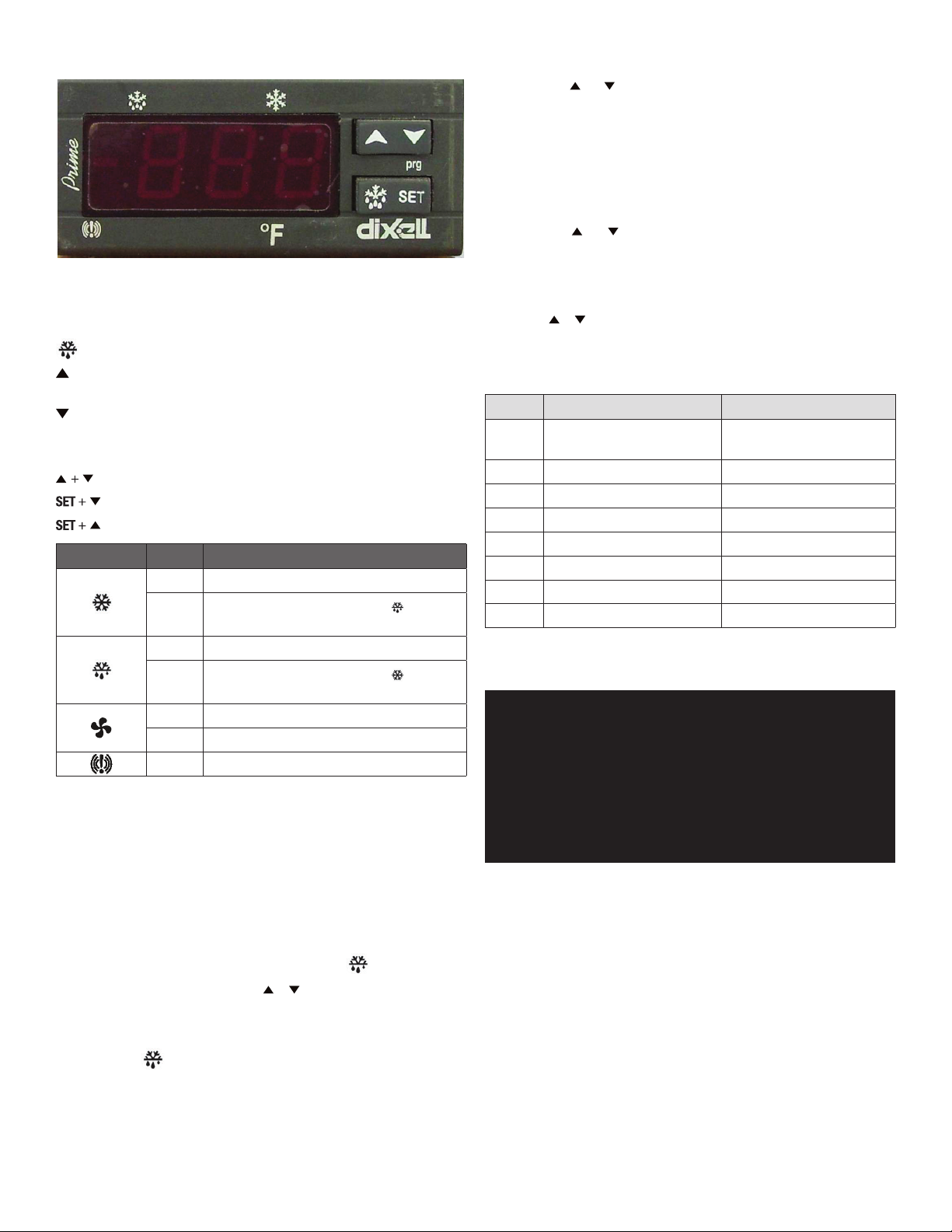
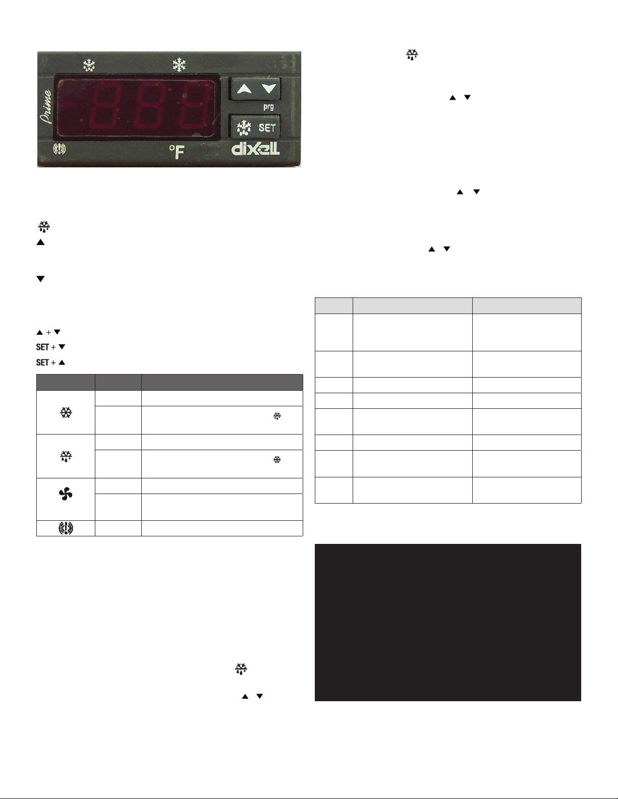
CONTROL PANEL SOLID-STATE THERMOSTAT
FRONT PANEL COMMANDS
SET SET: To display target set point; in programming mode, it selects a
parameter or conrms an operation.
DEF: To start a manual defrost
UP: To view last alarm occurrence; in programming mode, it browses the
parameter codes or increases the display value
DOWN: To view last alarm occurrence; in programming mode, it browses
the parameter codes or decreases the display value
Key Combination:
To lock & unlock the keyboard
To enter in programming mode
To return to the room temperature display
LED MODE FUNCTION
On Compressor enabled
Flashing
Programming phase (ashing with
Anti-short cycle delay enabled
On Defrost enabled
)
4. How to Lock the Keyboard
1. Hold the and keys for more than 3 seconds.
2. The “POF” message will be displayed and the keyboard will be locked. At
this point, it will be possible only to see the set point or the MAX or MIN
temperature stored.
3. If a key is pressed for more than 3 seconds, the ”POF” message will be
displayed.
5. How to Unlock the Keyboard
1. Hold the and keys together for more than 3 seconds, until the “POF”
message is displayed.
ALARM SIGNALS
How to See the Alarm and Reset the Recorded Alarm
1. Hold the or key to display the alarm signals.
2. When the signal is displayed, hold the SET key until the “rst” message is
displayed. Push the SET key again. The “rst” message starts blinking and the
normal temperature will be displayed again.
MESSAGE CAUSE OUTPUTS
“P1” Room probe failure
Compressor output according
to par. “Con” and “COF”
“P2” Evaporator probe failure Defrost end is timed
“HA” Maximum temperature alarm Outputs unchanged
“LA” Minimum temperature alarm Outputs unchanged
“dA” Door open Compressor and fans restarts
“EA” External alarm Output unchanged
“CA” Serious external alarm (i1F=bAL) All outputs OFF
“CA” Pressure switch alarm (i1F=PAL) All outputs OFF
Flashing
Programming phase (ashing with
Dripping in progress
)
On Fans enabled
Flashing Fans delay after defrost in progress
On A temperature alarm happened
MAIN FUNCTIONS
1. How to See the Setpoint
1. Push and immediately release the SET key: the display will show the set
point value.
2. Push and immediately release the SET key or wait for 5 seconds to display
the sensor value again.
2. How to Change the Setpoint
1. Hold the SET key for more than 2 seconds to change the set point value.
2. The value of the set point will be displayed and the
3. To change the set value, push the
or key within 10 seconds.
LED starts blinking.
4. To set new point value, push the SET key again or wait 10 seconds.
3. How to Start a Manual Defrost
1. Hold the
key for more than 2 seconds and a manual defrost will start.
MAINTENANCE
DANGER:
DANGER:
DANGER: NEVER USE STEEL PADS, WIRE BRUSHES OR SCRAPERS!
CAUTION: NEVER USE AN ACID BASED CLEANING SOLUTION!MANY FOOD PRODUCTS
REFRIGERATORS AND FREEZERS
The interior and exterior can be cleaned using soap and warm water. If this isn’t
sufcient, try ammonia and water or a nonabrasive liquid cleaner. When cleaning
the exterior, always rub with the “grain” of the stainless steel to avoid marring
the nish.
Do not use an abrasive cleaner because it will scratch the stainless steel and
plastic and can damage the breaker strips and gaskets.
CLEANING THE CONDENSER COIL
The condenser coil requires regular cleaning. Cleaning is recommended every
90 days. In some instances, you may nd that there is a large amount of debris
and dust or grease accumulated prior to the 90 day time frame. In these cases
the condenser coil should be cleaned every 30 days.
If the build up on the coil consists of only light dust and debris, the condenser
coil can be cleaned with a simple brush. Heavier dust build-up may require a
vacuum or even compressed air to blow through the condenser coil.
THE POWER SWITCH MUST BE TURNED OFF AND THE UNIT DISCONNECTED
FROM THE POWER SOURCE WHENEVER PERFORMING SERVICE,
MAINTENANCE FUNCTIONS OR CLEANING THE REFRIGERATED AREA.
NEVER USE A HIGH PRESSURE WATER WASH FOR THIS CLEANING
PROCEDURE AS WATER CAN DAMAGE THE ELECTRICAL COMPONENTS
LOCATED NEAR OR AT THE CONDENSER COIL.
HAVE AN ACIDIC CONTENT WHICH CAN DETERIORATE THE FINISH. BE SURE
TO CLEAN THE STAINLESS STEEL SURFACES OF ALL FOOD PRODUCTS.
4 FOOD PREP TABLES
Page 5

If heavy grease is present, there are de-greasing agents available for refrigeration
use and specically for the condenser coils. The condenser coil may require
cleaning with the de-greasing agent and then blown through with compressed
air.
Failure to maintain a clean condenser coil can initially cause high temperatures
and excessive run times. Continuous operation with dirty or clogged condenser
coils can result in compressor failures. Neglecting the condenser coil cleaning
procedures will void any warranties associated with the compressor or cost to
replace the compressor.
In order to maintain proper refrigeration performance, the condenser ns must
be cleaned of dust, dirt and grease regularly. It is recommended that this be
done at least every three months. If conditions are such that the condenser is
totally blocked in three months, the frequency of cleaning should be increased.
Clean the condenser with a vacuum cleaner or stiff brush. If extremely dirty, a
commercial-grade condenser cleaner may be required.
STAINLESS STEEL CARE AND CLEANING
To prevent discoloration of rust on stainless steel, several important steps
need to be taken. First, we need to understand the properties of stainless steel.
Stainless steel contains 70-80% iron which will rust. It also contains 12-30%
chromium which forms an invisible passive lm over the steels surface which
acts as a shield against corrosion. As long as the protective layer is intact, the
metal is still stainless. If the lm is broken or contaminated, outside elements
can begin to breakdown the steel and begin to form rust of discoloration.
Proper cleaning of stainless steel requires soft cloths or plastic scouring pads.
Cleaning solutions need to be alkaline based or non-chloride based. Any cleaner
containing chlorides will damage the protective lm of the stainless steel.
Chlorides are commonly found in hard water, salts, and household and industrial
cleaners. If cleaners containing chlorides are used, be sure to rinse and dry
thoroughly.
Routine cleaning of stainless steel can be done with soap and water. Extreme
stains or grease should be cleaned with a non-abrasive cleaner and plastic scrub
pad. It is always good to rub with the grain of the steel. There are also stainless
steel cleaners available which can restore and preserve the nish of the steels
protective layer.
Early signs of stainless steel breakdown can consist of small pits and cracks.
If this has begun, clean thoroughly and start to apply stainless steel cleaners in
attempt to restore the passivity of the steel.
GASKET MAINTENANCE
Gaskets require regular cleaning to prevent mold and mildew build up and also
to keep the elasticity of the gasket. Gasket cleaning can be done with the use of
warm soapy water. Avoid full strength cleaning products on gaskets as this can
cause them to become brittle and prevent proper seals. Do not use sharp tools
or knives to scrape or clean the gasket which could possibly tear the gasket and
rip the bellows.
Gaskets can easily be replaced and don’t require the use of tools or authorized
service technicians. The gaskets are “Dart” style and can be pulled out of the
grove in the door and replaced by pressing the new one back into place.
DOORS/HINGES
Over time and with heavy use, door hinges may become loose. If the door is
beginning to sag, tighten the screws that mount the hinge brackets to the frame
of the unit. If the doors are loose or sagging this can cause the hinge to pull out
of the frame which may damage to both the doors and the door hinges.
DRAIN MAINTENANCE
Each unit has a drain located inside the unit which removes the condensation
from the evaporator coil and evaporates it into an external condensate evaporator
pan. Each drain can become loose or disconnected from moving or bumping the
drain. If you notice excessive water accumulation on the inside of the unit, be
sure the drain tube is connected from the evaporator housing to the condensate
evaporator drain pan. If water starts to collect underneath the unit, you may want
to check the condensate evaporator drain tube to be sure it is still located inside
the drain pan. The leveling of the unit is important as the units are designed to
drain properly when on a level surface. If your oor is not level this can also
cause drain problems. Be sure all drain lines are free of obstructions because
this may cause water to back up and overow the drain pans.
5 FOOD PREP TABLES
Page 6
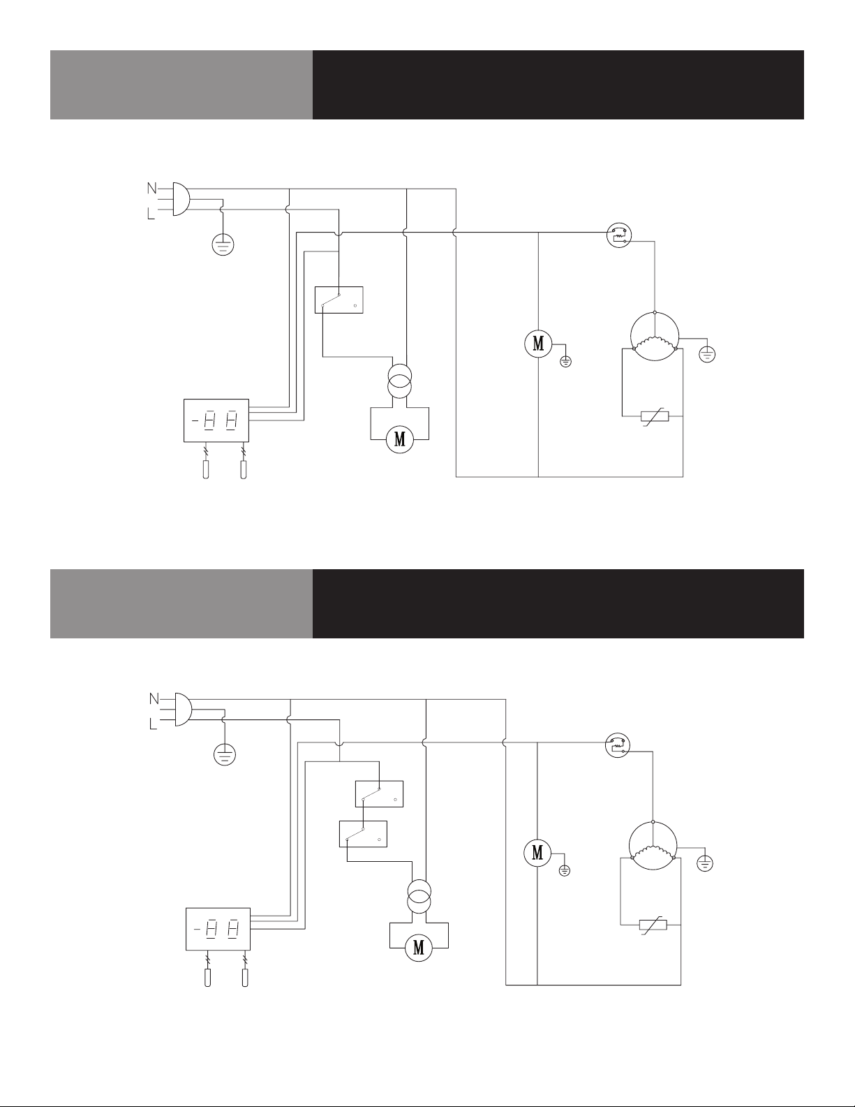
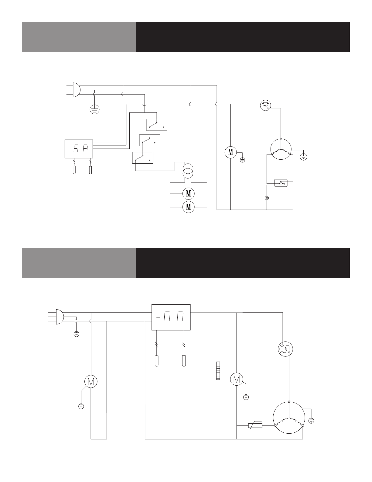
KCHUC27R / KCHUCWT27R / KCHUC27.2DR
CALL FACTORY FOR REPLACEMENT PARTS:
866-738-1640
Wiring Diagram
PLUG
THERMOSTAT DISPLAY
ROOM
SENSOR
KCHUC48R / KCHUCWT48R / KCHUC60R /
KCHUCWT60R
CALL FACTORY FOR REPLACEMENT PARTS:
866-738-1640
EVAP
DOOR
SWITCH
FAN
POWER
EVAP
FAN
OVERLOAD
PROTECTOR
CONDENSEN
FAN
PTC
STARTER
Wiring Diagram
COMPRESSOR
PLUG
THERMOSTAT DISPLAY
ROOM
6 FOOD PREP TABLES
SENSOR
EVAP
DOOR
SWITCH
EVAP
FAN
FAN
POWER
OVERLOAD
PROTECTOR
CONDENSEN
FAN
COMPRESSOR
PTC
STARTER
Page 7
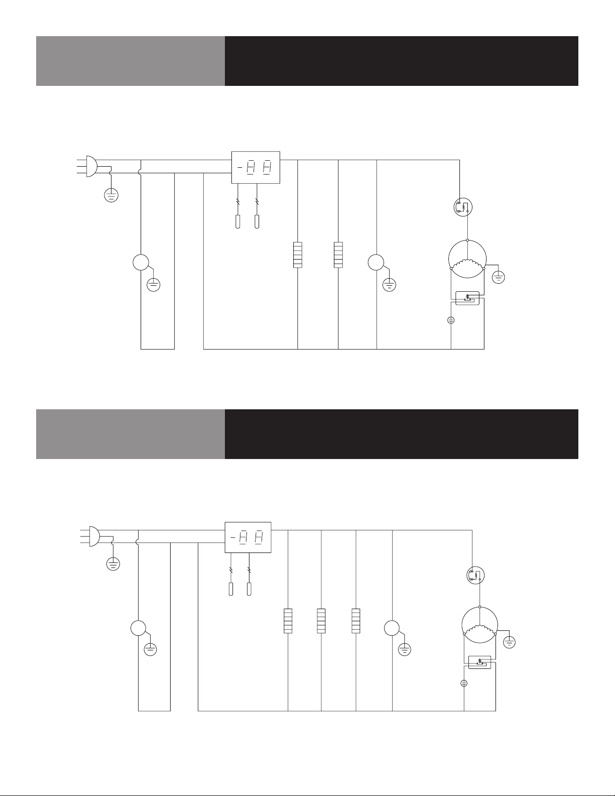
KCHUC72R / KCHUCWT72R
CALL FACTORY FOR REPLACEMENT PARTS:
866-738-1640
N
L
Wiring Diagram
PLUG
THERMOSTAT DISPLAY
ROOM
SENSOR
KCHPT50.6
CALL FACTORY FOR REPLACEMENT PARTS:
866-738-1640
EVAP
EVAP
FAN
DOOR
SWITCH
OVERLOAD
PROTECTOR
CONDENSEN
FAN
FAN
POWER
STARTING
CAPACITOR
Wiring Diagram
COMPRESSOR
CURRENT
RELAY
N
L
PLUG
CIRCUITALION
FAN MOTOR
7 FOOD PREP TABLES
THERMOSTAT DISPLAY
ROOM
EVAP
SENSOR
CONDENSER
FAN MOTOR
DOOR FRAME HEATER
t ˚C
PTC STARTER
OVERLOAD
PROTECTOR
COMPRESSOR
Page 8
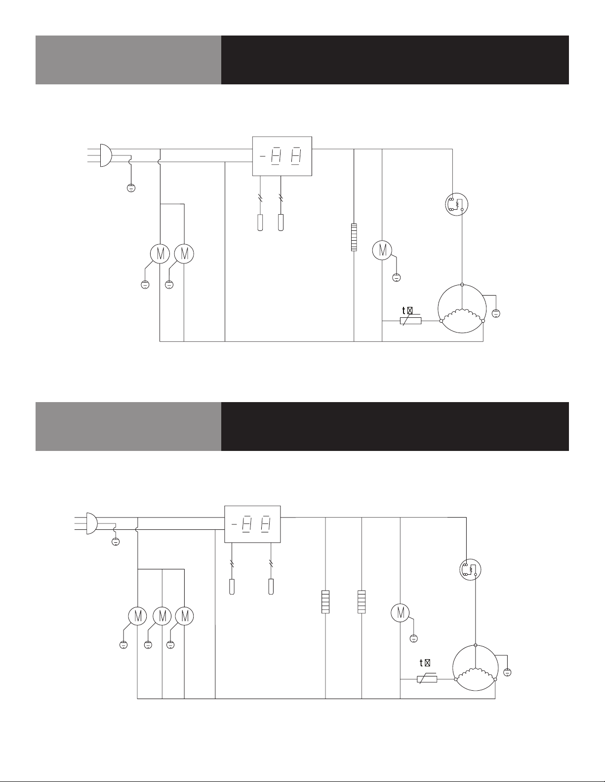
KCHPT60.9
CALL FACTORY FOR REPLACEMENT PARTS:
866-738-1640
N
L
PLUG
Wiring Diagram
THERMOSTAT DISPLAY
OVERLOAD
PROTECTOR
CIRCUITALION
FAN MOTOR
KCHPT70.12
CALL FACTORY FOR REPLACEMENT PARTS:
866-738-1640
ROOM
SENSOR
THERMOSTAT DISPLAY
EVAP
CONDENSER
FAN MOTOR
MM
DOOR FRAME HEATER
MIDDLE FRAME HEATER
STARTING
CAPACITOR
Wiring Diagram
COMPRESSOR
CURREN T
RELAY
N
L
PLUG
CIRCUITALION
FAN MOTOR
8 FOOD PREP TABLES
M
ROOM
SENSOR
EVAP
M
DOOR FRAME HEATER
MIDDLE FRAME HEATER
MIDDLE FRAME HEATER
OVERLOAD
PROTECTOR
COMPRESSOR
CONDENSER
FAN MOTOR
CURRENT
RELAY
STARTING
CAPACITOR
Page 9
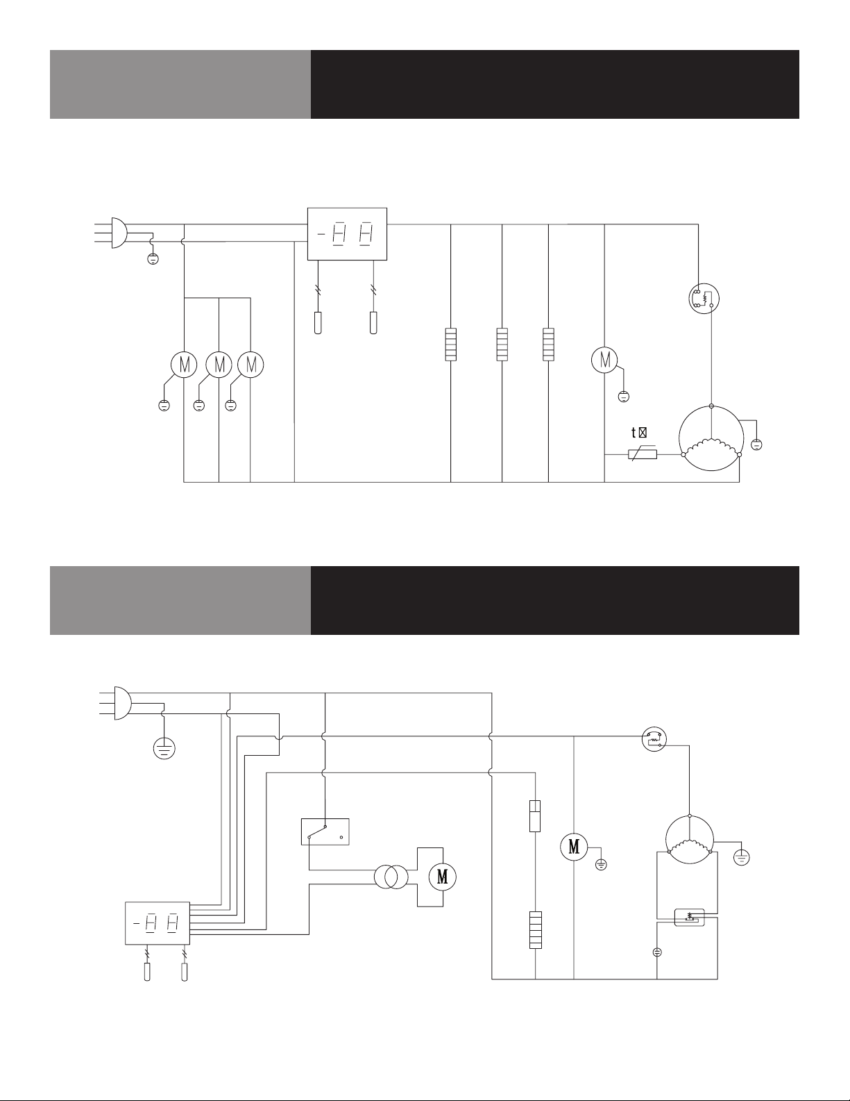
KCHST27.8 / KCHMT29.12 / KCHMT29.12.2D
CALL FACTORY FOR REPLACEMENT PARTS:
866-738-1640
N
L
PLUG
Wiring Diagram
THERMOSTAT DISPLAY
OVERLOAD
PROTECTOR
CIRCUITALION
FAN MOTOR
KCHST48.12 / KCHMT48.18 / KCHMT48.18.2D /
KCHST60.16 / KCHMT60.24 / KCHMT60.24.2D
CALL FACTORY FOR REPLACEMENT PARTS:
866-738-1640
ROOM
EVAP
SENSOR
THERMOSTAT DISPLAY
CONDENSER
FAN MOTOR
DOOR FRAME HEATER
PTC STARTER
Wiring Diagram
COMPRESSOR
N
L
PLUG
CIRCUITALION
FAN MOTOR
9 FOOD PREP TABLES
ROOM
SENSOR
EVAP
CONDENSER
FAN MOTOR
DOOR FRAME HEATER
MIDDLE FRAME HEATER
OVERLOAD
PROTECTOR
COMPRESSOR
PTC STARTER
Page 10
KCHST70.18 / KCHMT70.30
CALL FACTORY FOR REPLACEMENT PARTS:
866-738-1640
N
L
PLUG
Wiring Diagram
THERMOSTAT DISPLAY
OVERLOAD
PROTECTOR
CIRCUITALION
FAN MOTOR
KCHUC27F / KCHUCWT27F
CALL FACTORY FOR REPLACEMENT PARTS:
866-738-1640
N
L
ROOM
SENSOR
EVAP
CONDENSER
FAN MOTOR
DOOR FRAME HEATER
MIDDLE FRAME HEATER
MIDDLE FRAME HEATER
Wiring Diagram
COMPRESSOR
PTC STARTER
PLUG
THERMOSTAT DISPLAY
ROOM
SENSOR
10 FOOD PREP TABLES
EVAP
DOOR
SWITCH
FAN
POWER
EVAP
FAN
THERMAL
CUT-OFF
CONDENSER
FAN
DEFROST HEATER
OVERLOAD
PROTECTOR
STARTING
CAPACITOR
COMPRESSOR
CURRENT
RELAY
Page 11
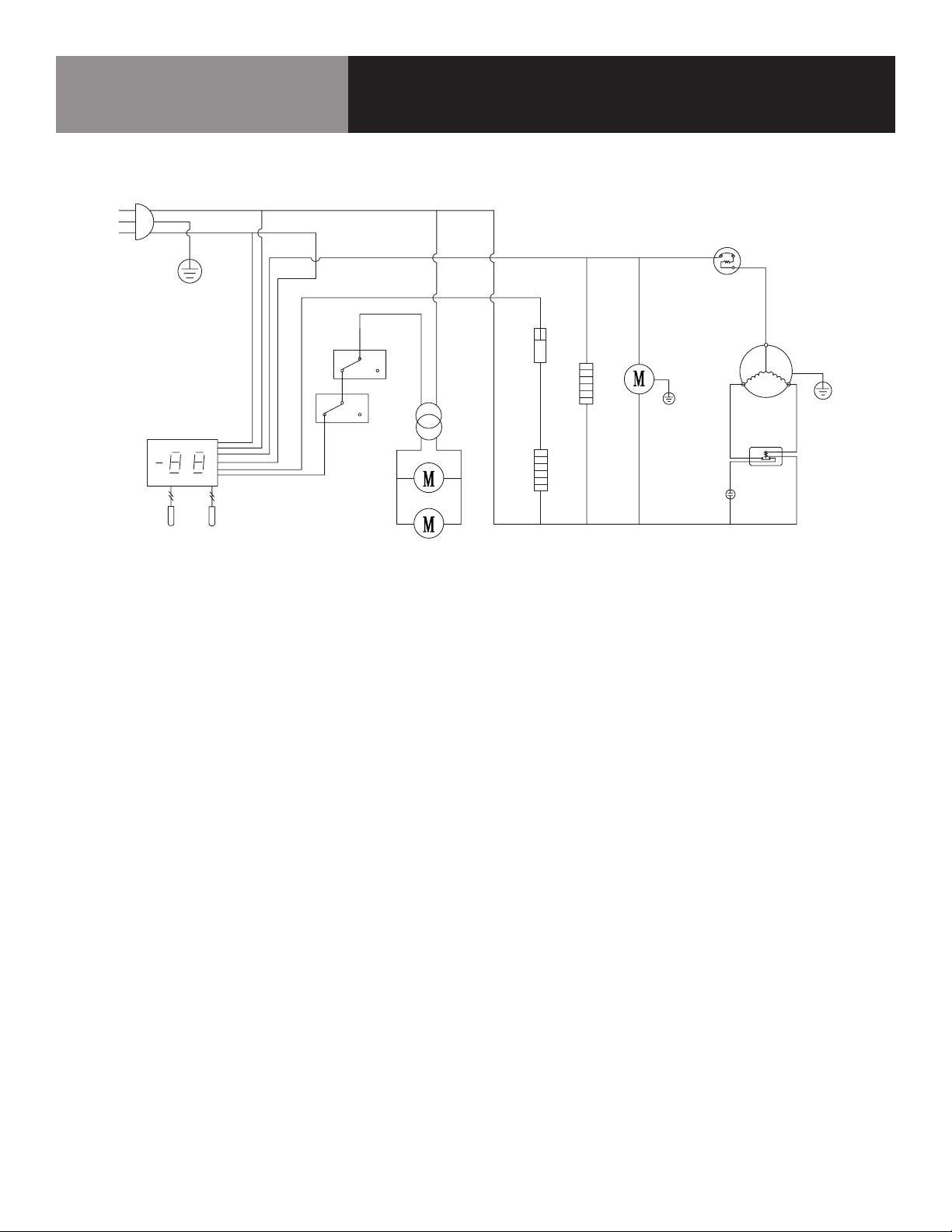
KCHUC48F / KCHUCWT48F
CALL FACTORY FOR REPLACEMENT PARTS:
866-738-1640
N
L
Wiring Diagram
PLUG
THERMOSTAT DISPLAY
ROOM
SENSOR
EVAP
DOOR
SWITCH
EVAP
FAN
FAN
POWER
THERMAL
CUT-OFF
DEFROST HEATER
OVERLOAD
PROTECTOR
CONDENSER
FAN
MIDDLE FRAME HEATER
STARTING
CAPACITOR
CURRENT
RELAY
COMPRESSOR
11 FOOD PREP TABLES
Page 12
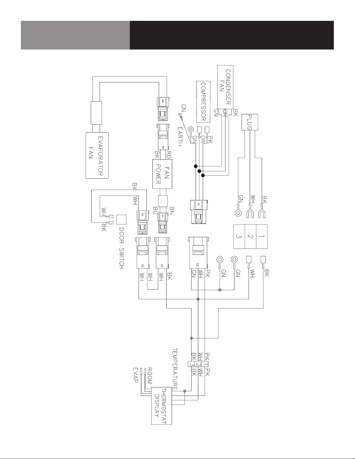
KCHUC27R / KCHUCWT27R / KCHUC27.2DR
CALL FACTORY FOR REPLACEMENT PARTS:
866-738-1640
Wiring Diagram
12 FOOD PREP TABLES
Page 13
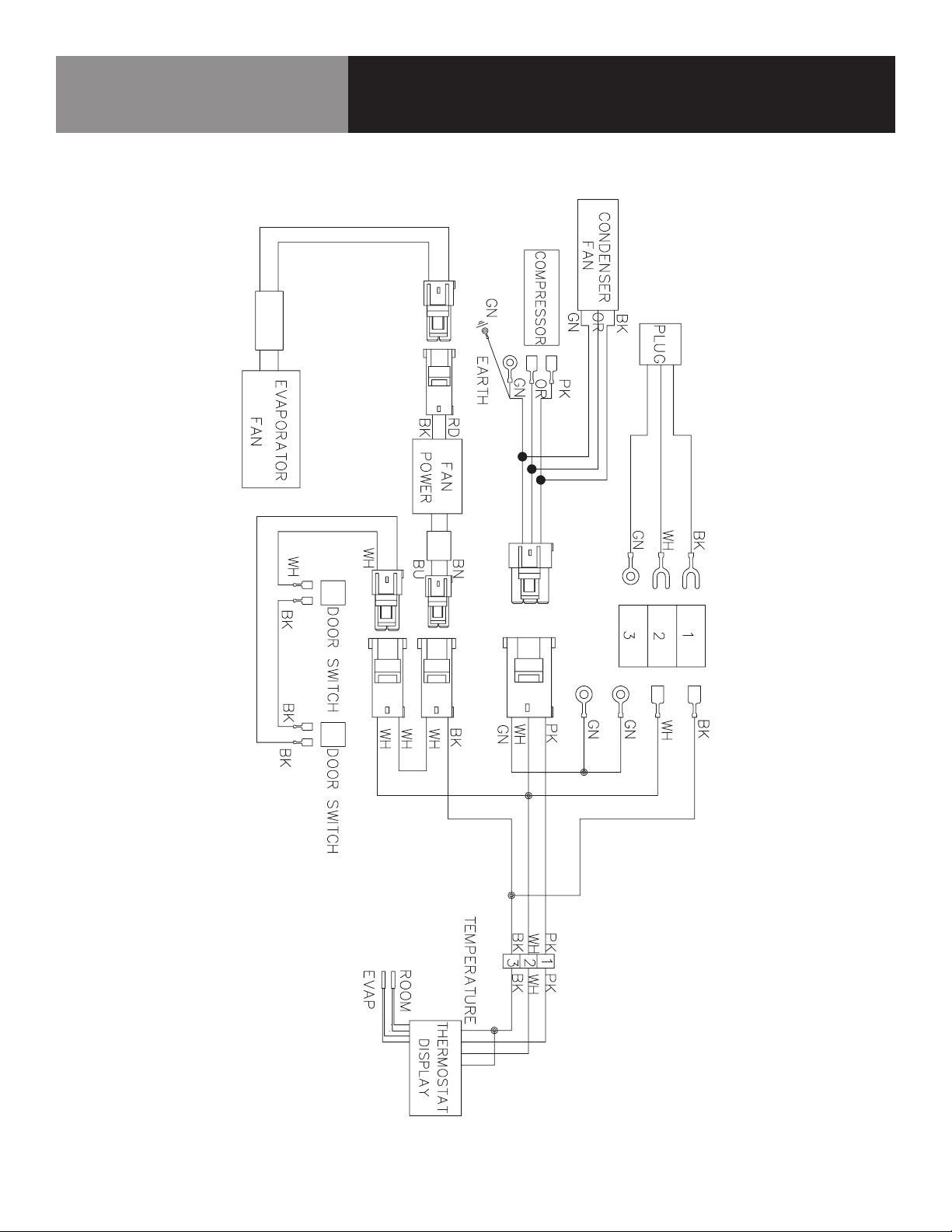
KCHUC48R / KCHUCWT48R / KCHUC60R /
KCHUCWT60R
CALL FACTORY FOR REPLACEMENT PARTS:
866-738-1640
Wiring Diagram
13 FOOD PREP TABLES
Page 14
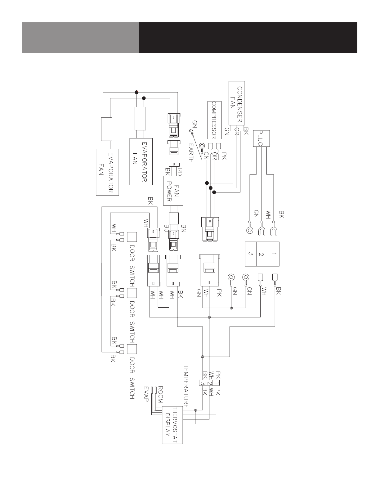
KCHUC72R / KCHUCWT72R
CALL FACTORY FOR REPLACEMENT PARTS:
866-738-1640
Wiring Diagram
14 FOOD PREP TABLES
Page 15
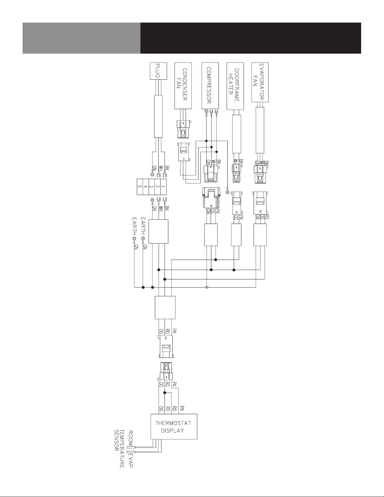
KCHST27.8 / KCHMT29.12 / KCHMT29.12.2D
CALL FACTORY FOR REPLACEMENT PARTS:
866-738-1640
Wiring Diagram
15 FOOD PREP TABLES
Page 16
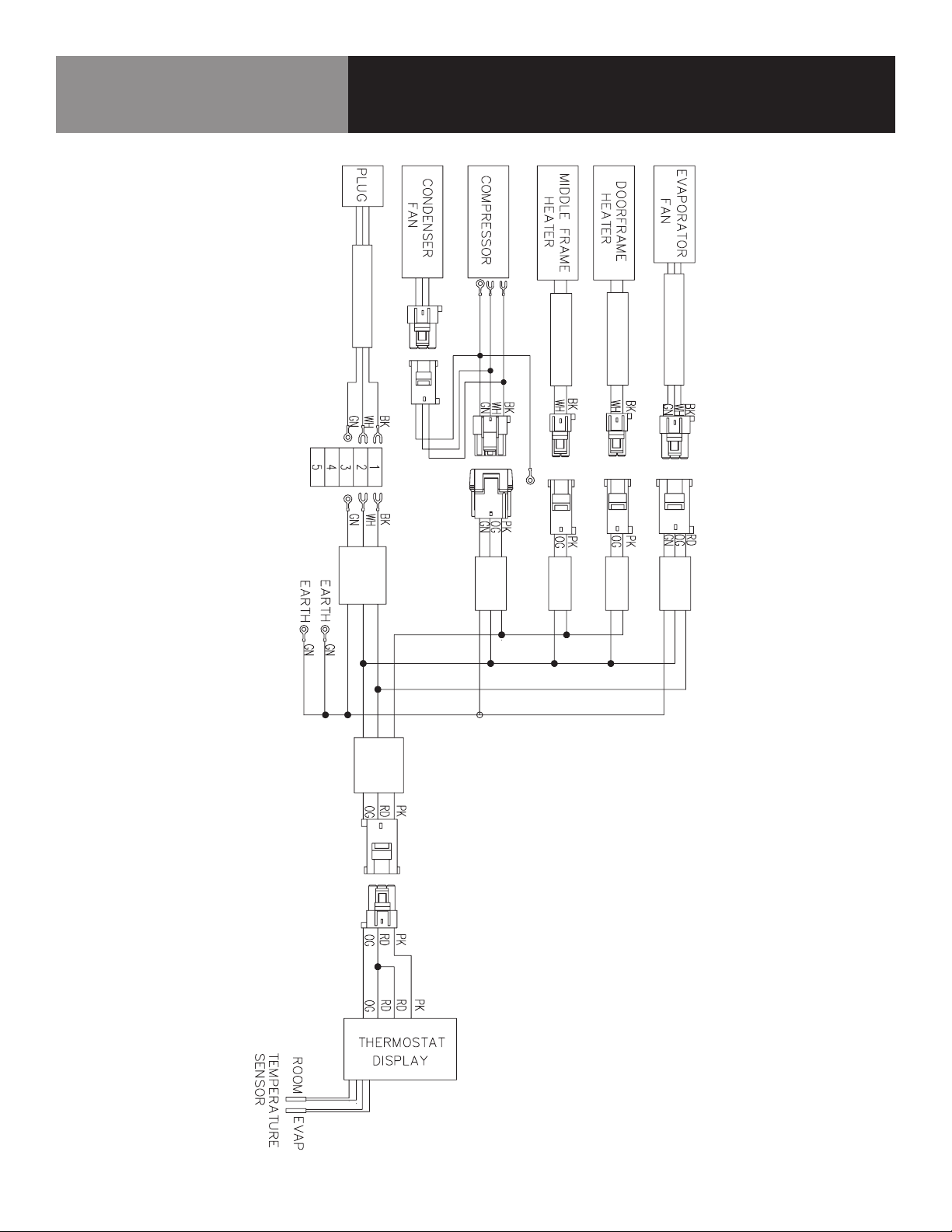
KCHST48.12 / KCHMT48.18 / KCHMT48.18.2D /
KCHST60.16 / KCHMT60.24 / KCHMT60.24.2D
CALL FACTORY FOR REPLACEMENT PARTS:
866-738-1640
Wiring Diagram
16 FOOD PREP TABLES
Page 17
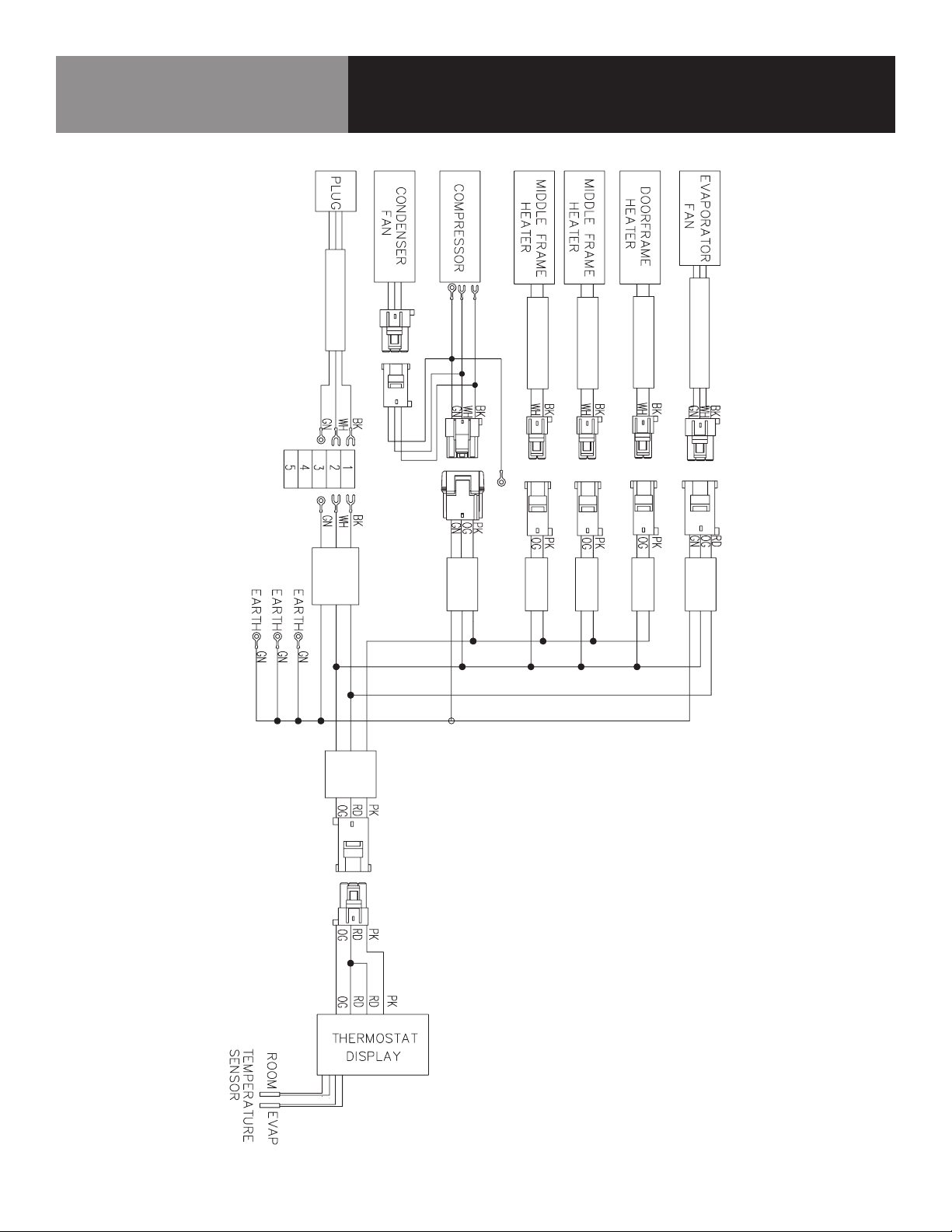
KCHST70.18 / KCHMT70.30
CALL FACTORY FOR REPLACEMENT PARTS:
866-738-1640
Wiring Diagram
17 FOOD PREP TABLES
Page 18
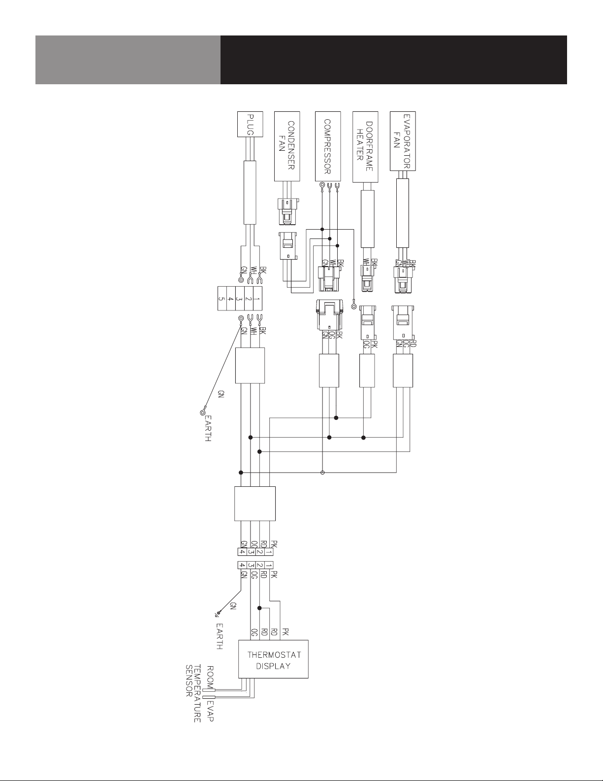
KCHPT50.6
CALL FACTORY FOR REPLACEMENT PARTS:
866-738-1640
Wiring Diagram
18 FOOD PREP TABLES
Page 19
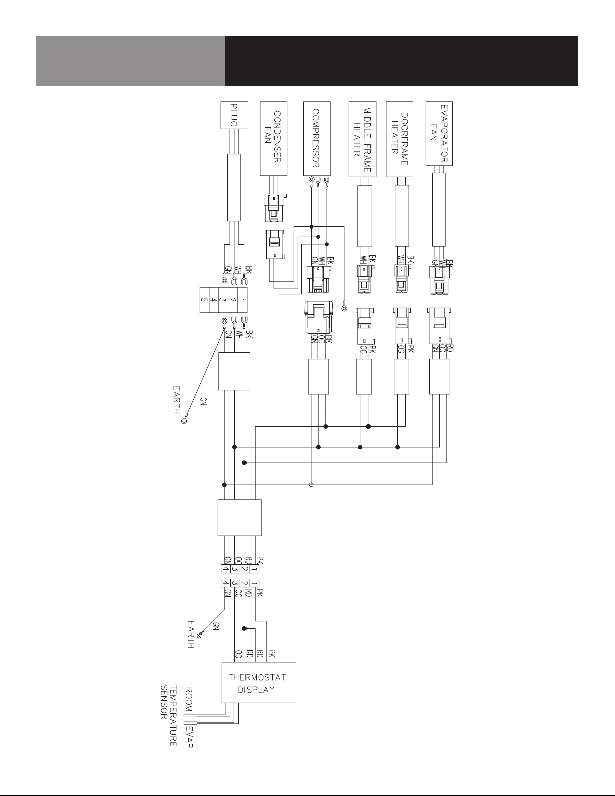
KCHPT60.9
CALL FACTORY FOR REPLACEMENT PARTS:
866-738-1640
Wiring Diagram
19 FOOD PREP TABLES
Page 20
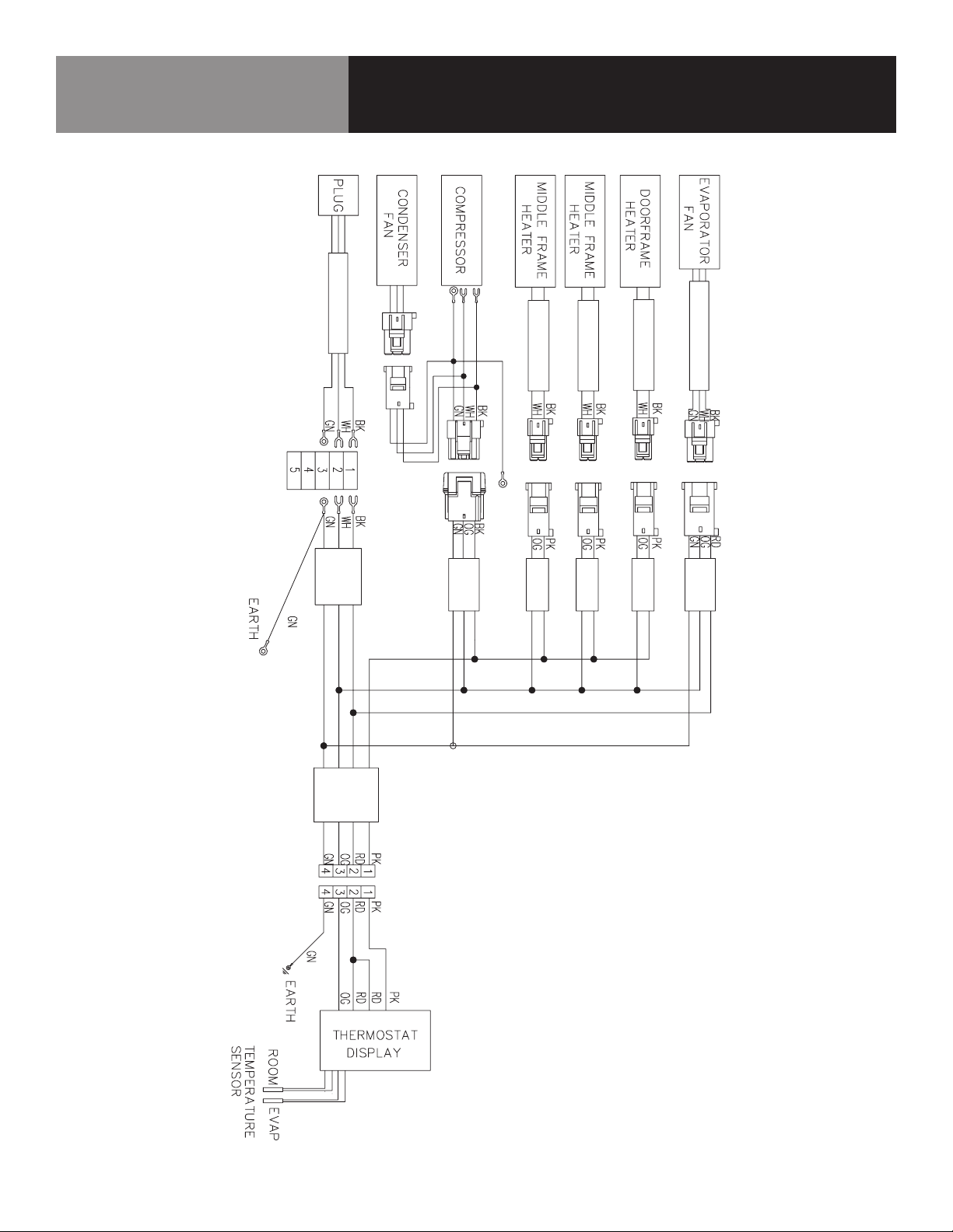
KCHPT70.12
CALL FACTORY FOR REPLACEMENT PARTS:
866-738-1640
Wiring Diagram
20 FOOD PREP TABLES
Page 21
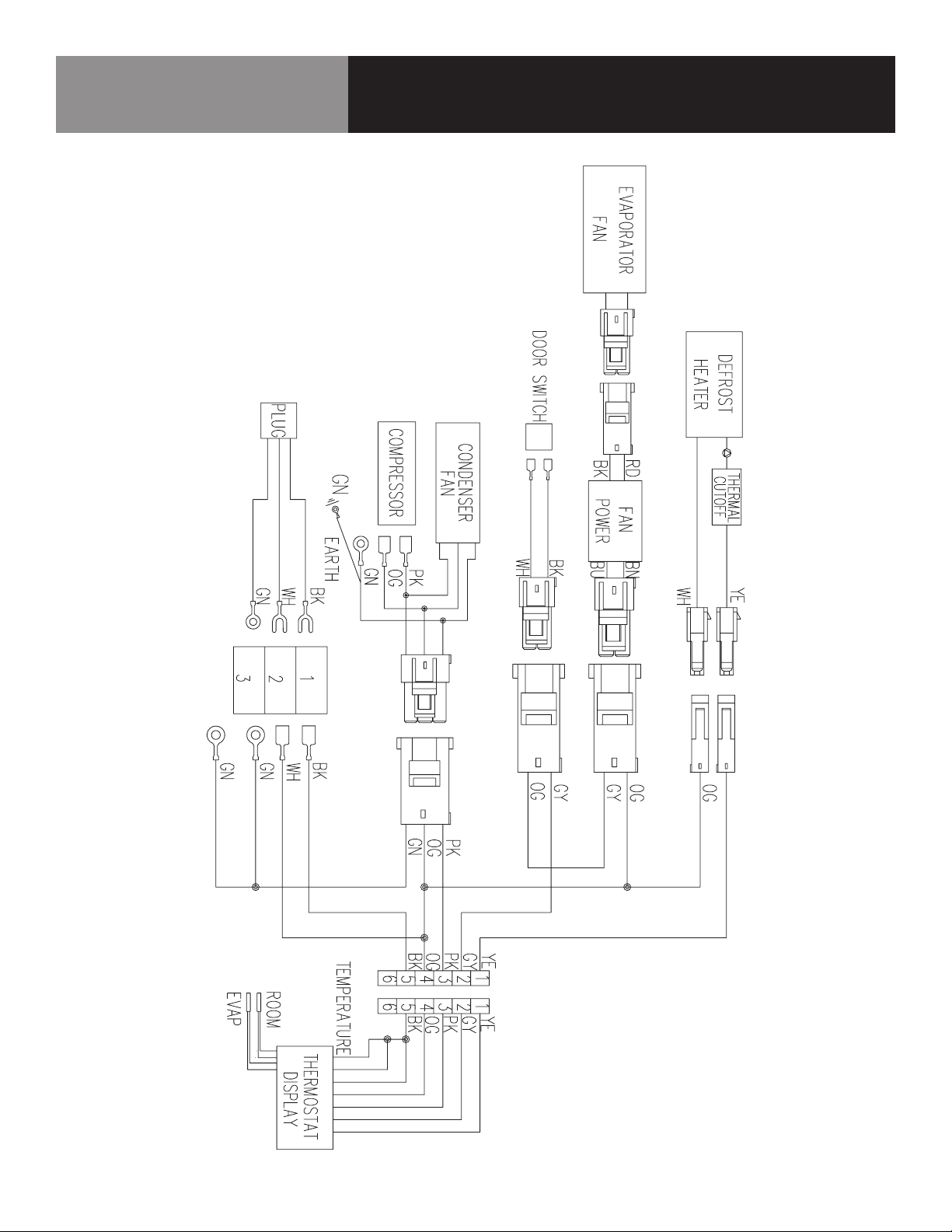
KCHUC27F / KCHUCWT27F
CALL FACTORY FOR REPLACEMENT PARTS:
866-738-1640
Wiring Diagram
21 FOOD PREP TABLES
Page 22
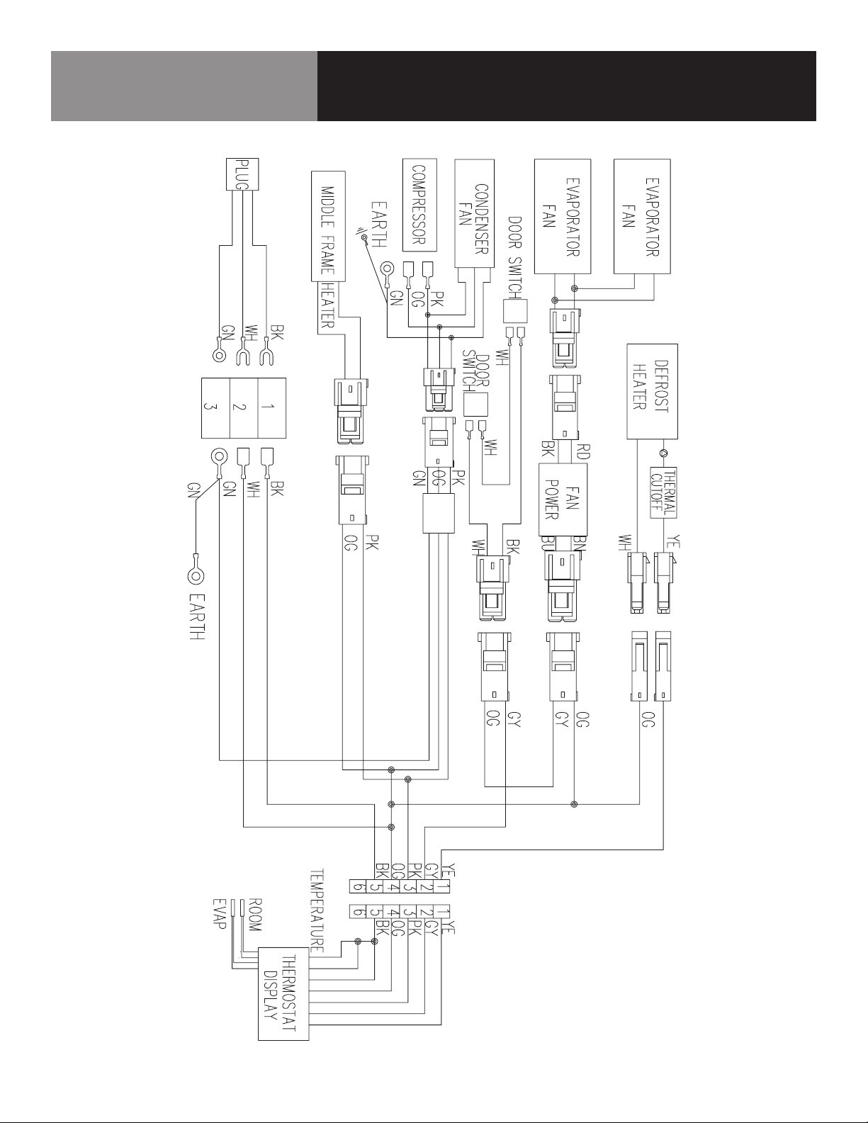
KCHUC48F / KCHUCWT48F
CALL FACTORY FOR REPLACEMENT PARTS:
866-738-1640
Wiring Diagram
22 FOOD PREP TABLES
Page 23

WARRANTY
Your appliance is covered by a three (3) year limited warranty. For three (3) years from
your original date of purchase, Electrolux will pay all costs, except as set forth below, for
repairing or replacing any parts of this appliance that prove to be defective in materials
or workmanship when such appliance is installed, used, and maintained in accordance
with the provided instructions. For appliances that are manufactured with a compressor,
an additional two (2) year part warranty is provided for the compressor only.
EXCLUSIONS
THIS WARRANTY DOES NOT COVER THE FOLLOWING:
1. Products where the original serial number has been removed, altered or cannot be
readily determined.
2. Normal wear and tear and gradual deterioration.
3. Product that has been transferred from its original owner to another party or
moved outside the USA or Canada.
4. Rust on the interior or exterior of the unit.
5. Products purchased “as-is”.
6. Food loss due to any refrigerator or freezer failures.
7. Damage caused at any time during shipment.
8. Service calls which do not involve malfunction or defects in materials or
workmanship, or for appliances used other than in accordance with the provided
instructions.
9. Service calls to correct the installation of your appliance or to instruct you how to
use your appliance.
10. Expenses for making the appliance accessible for servicing, such as removal of
trim, cupboards, shelves, etc., which are not a part of the appliance when it is
shipped from the factory.
11. Service calls to replace appliance light bulbs, air lters, water lters, and other
consumables, or knobs, handles, and other cosmetic parts.
12. Surcharges including, but not limited to, any after hours, weekend, or holiday
service calls, tolls, ferry trip charges, or mileage expense for service calls to
remote areas, including the state of Alaska.
13. Damages to the nish of the appliance and/or the appliance location that are
incurred during installation, including but not limited to oors, cabinets, walls, etc.
14. Damages caused by: services performed by unauthorized service companies; use
of parts other than genuine Electrolux parts or parts obtained from persons other
than authorized service companies; or external causes such as abuse, misuse,
inadequate power supply, accidents, res, or acts of God.
15. For appliances operated by a concessionaire or vendor in a trailer or other
motorized vehicle, or at varying locations, your appliance is covered by a one
(1) year, limited parts and labor warranty. For appliances that are manufactured
with a compressor, an additional four (4) year part warranty is provided for the
compressor only.
DISCLAIMER OF IMPLIED WARRANTIES; LIMITATION OF REMEDIES
CUSTOMER’S SOLE AND EXCLUSIVE REMEDY UNDER THIS LIMITED WARRANTY SHALL
BE PRODUCT REPAIR OR REPLACEMENT AS PROVIDED HEREIN. CLAIMS BASED ON
IMPLIED WARRANTIES, INCLUDING WARRANTIES OF MERCHANTABILITY OR FITNESS
FOR A PARTICULAR PURPOSE, ARE LIMITED TO ONE (1) YEAR OR THE SHORTEST
PERIOD ALLOWED BY LAW, BUT NOT LESS THAN ONE (1) YEAR. ELECTROLUX
SHALL NOT BE LIABLE FOR CONSEQUENTIAL OR INCIDENTAL DAMAGES SUCH AS
PROPERTY DAMAGE AND INCIDENTAL EXPENSES RESULTING FROM ANY BREACH
OF THIS WRITTEN LIMITED WARRANTY OR ANY IMPLIED WARRANTY. SOME STATES
AND PROVINCES DO NOT ALLOW THE EXCLUSION OR LIMITATION OF INCIDENTAL
OR CONSEQUENTIAL DAMAGES, OR LIMITATIONS ON THE DURATION OF IMPLIED
WARRANTIES, SO THESE LIMITATIONS OR EXCLUSIONS MAY NOT APPLY TO YOU.
THIS WRITTEN WARRANTY GIVES YOU SPECIFIC LEGAL RIGHTS. YOU MAY ALSO HAVE
OTHER RIGHTS THAT VARY FROM STATE TO STATE.
If You Need Service
In order to obtain service the unit must rst be registered at KelvinatorCommercial.
com. Once registered please call 866-738-1640 for assistance.
This warranty only applies in the USA and Canada and is warranted by Electrolux
Professional Group SPA.
Electrolux authorizes no person to change or add to any obligations under this
warranty. Obligations for service and parts under this warranty must be performed
by Electrolux or an authorized service company. Product features or specications as
described or illustrated are subject to change without notice.
(December 2018)
1-866-738-1640
Electrolux Professional Group North America
23 FOOD PREP TABLES
Page 24
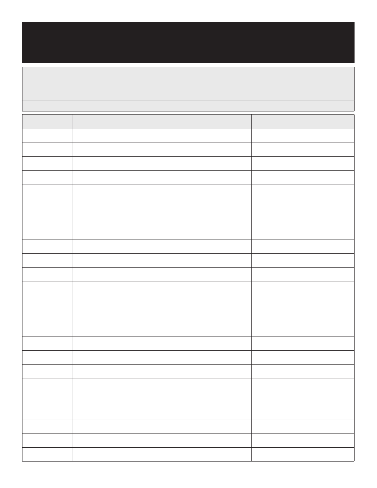
Service Log
Model No: Purchased From:
Serial No: Location:
Date Purchased: Date Installed:
Purchase Order No: For Service Call:
Date Maintenance Performed Performed By
24 FOOD PREP TABLES
Page 25
MANUAL DE SERVICIO/INSTALACIÓN
INFORMACIÓN IMPORTANTE,
CONSÉRVESE PARA EL USUARIO
Estados Unidos y Canadá, 866-738-1640
4003 Collins Lane, Louisville, KY 40245
www.kelvinatorcommercial.com
ESTE MANUAL DEBE CONSERVARSE PARA CONSULTAS FUTURAS.
ASEGÚRESE DE LEER, COMPRENDER Y CUMPLIR LAS INSTRUCCIONES Y
ADVERTENCIAS QUE CONTIENE ESTE MANUAL.
PARA SU SEGURIDAD No guarde ni utilice gasolina ni otros líquidos o
vapores inflamables cerca de este equipo ni de ningún otro.
NOTIFIQUE LOS DAÑOS AL TRANSPORTISTA DE MANERA INMEDIATA
Es responsabilidad del destinatario inspeccionar el contenedor al recibirlo
y determinar la posibilidad de cualquier daño, incluidos los daños ocultos.
Electrolux Professional Inc. recomienda que, si sospecha que se han
producido daños, anote un comentario en el recibo del material. Será
responsabilidad del destinatario presentar una reclamación al transportista.
Es conveniente que lo haga de inmediato.
Servicio de fabricación/consultas 866-738-1640.
DESCRIPCIÓN DEL EQUIPO
REFERENCIA DE PIEZA HB_738371_9F73837100, REV. A (03/23)
REV. B (06/23)
Este manual contiene información sobre:
MESA REFRIGERADA PREPARACION
ENSALADAS / SANDWICHES, MESA
REFRIGERADA PREPARACIÓN DE
PIZZA, REFRIGERADOR Y CONGELADOR
BAJOMOSTRADOR
CONSERVE ESTE MANUAL PARA CONSULTAS FUTURAS
AVISO: Debido a un programa continuo de mejora del producto, Electrolux
Professional Inc. se reserva el derecho de realizar cambios en el diseño y las
especificaciones sin previo aviso.
antes de la instalación. Si no se siguen ciertos procedimientos recomendados,
se rechazarán las reclamaciones de garantía.
El número de serie de todas las neveras y congeladores autónomos se encuentra
fuera de la unidad, en el lado izquierdo, cerca de la parte superior. Tenga siempre
a mano el número de serie de la unidad cuando llame para solicitar piezas
o servicio técnico. Este manual trata solamente sobre unidades estándar. Si
tiene una unidad personalizada, consulte al servicio de atención al cliente en el
número que aparece en este manual.
AVISO: Lea detenidamente todo el manual
UNIDADES PARA SÁNDWICHES/ENSALADAS
CAPACIDAD
N.º DE MODELO V/HZ/PH AMPERIOS
KCHST27.8 115/60/1 3,0 7/0,20 14/1,3 8 1/3 853 3,0 276/125 5-15P
KCHST48.12 115/60/1 4,3 12/0,34 26/2,41 12 1/2 1365 3,17 313/142 5-15P
KCHST60.16 115/60/1 4,3 15,5/0,44 30/2,79 16 1/2 1365 3,17 362/164 5-15P
KCHST70.18 115/60/1 4,3 18/0,51 36/3,34 18 1/2 1365 3,17 408/185 5-15P
ALMACENAMIENTO
3/M3
)
(PIES
ESTANTE
(PIES2/M2)
BANDEJA
1/6
TAMAÑO
HP BTU
ONZAS DE
CARGA
PESO DE
ENVÍO LB/KG
ENCHUFE
NEMA
UNIDADES MEGATOP PARA SÁNDWICHES/ENSALADAS
CAPACIDAD
N.º DE MODELO V/HZ/PH AMPERIOS
KCHMT29.12 115/60/1 3,0 7/0,20 14/1,3 12 3/8 853 3,0 276/125 5-15P
KCHMT29.12.2D 115/60/1 3,0 7/0,20 - 12 3/8 853 3,0 276/125 5-15P
KCHMT48.18 115/60/1 4,3 12/0,34 26/2,4 18 1/2 1365 3,17 313/142 5-15P
KCHMT48.18.2D 115/60/1 4,3 12/0,34 13/1,2 18 1/2 1365 3,17 313/142 5-15P
KCHMT60.24 115/60/1 4,3 15,5/0,44 30/2,8 24 1/2 1365 3,17 362/164 5-15P
KCHMT60.24.2D 115/60/1 4,3 15,5/0,44 15/1,4 24 1/2 1365 3,17 362/164 5-15P
KCHMT70.30 115/60/1 4,3 18/0,51 36/3,3 18 1/2 1365 3,17 408/185 5-15P
ALMACENAMIENTO
3/M3
)
(PIES
ESTANTE
(PIES2/M2)
BANDEJA
1/6
TAMAÑO
HP BTU
ONZAS DE
CARGA
PESO DE
ENVÍO LB/KG
ENCHUFE
NEMA
La información que contiene este documento se considera actual y exacta en el momento de su impresión/creación. Consulte el sitio web de nuestra línea de productos para obtener la
información y las especificaciones más actualizadas. © 2023 Electrolux Professional, Inc. Todos los derechos reservados.
Page 26
IMPORTANTE - LÉASE PRIMERO - IMPORTANTE
SU SEGURIDAD Y LA DE LOS DEMÁS SON MUY IMPORTANTES.
EN ESTE MANUAL Y EN EL EQUIPO ENCONTRARÁ NUMEROSOS MENSAJES DE SEGURIDAD
IMPORTANTES. LEA Y CUMPLA SIEMPRE TODOS LOS MENSAJES DE SEGURIDAD.
LAS INSTRUCCIONES SOBRE NUESTROS PRODUCTOS SE CARGARÁN EN EL SITIO WEB
OFICIAL DE NUESTRA EMPRESA.
ESTE ES EL SÍMBOLO DE ALERTA SOBRE SEGURIDAD. ESTE SÍMBOLO ALERTA
DE RIESGOS POTENCIALES QUE PUEDEN PROVOCAR HERIDAS O MUERTE AL
USUARIO O A OTRAS PERSONAS. TODOS LOS MENSAJES DE SEGURIDAD
IRÁN SEGUIDOS DE LOS SÍMBOLOS DE ALERTA DE SEGURIDAD Y DE LAS
PALABRAS "PELIGRO", "ADVERTENCIA" O "PRECAUCIÓN".
PELIGRO SIGNIFICA QUE EL INCUMPLIMIENTO DE ESTA INDICACIÓN DE
SEGURIDAD PUEDE PROVOCAR LESIONES GRAVES O MUERTE.
ADVERTENCIA SIGNIFICA QUE SI NO SE TIENE EN CUENTA ESTE AVISO DE
SEGURIDAD SE PUEDEN PRODUCIR DAÑOS IMPORTANTES EN EL PRODUCTO,
LESIONES PERSONALES GRAVES O MUERTE.
PRECAUCIÓN SIGNIFICA QUE EL INCUMPLIMIENTO DE ESTA INDICACIÓN
DE SEGURIDAD PUEDE PROVOCAR LESIONES PERSONALES LEVES O
MODERADAS, O DAÑOS MATERIALES O EN EL EQUIPO.
TODOS LOS MENSAJES DE SEGURIDAD ALERTAN SOBRE CUÁL ES EL PELIGRO POTENCIAL,
INDICAN CÓMO REDUCIR EL RIESGO DE LESIONES E INFORMAN DE LO QUE PUEDE
OCURRIR SI NO SE SIGUEN LAS INSTRUCCIONES.
ADOPTE MEDIDAS DE PRECAUCIÓN BÁSICAS, INCLUIDAS LAS SIGUIENTES:
NOTA: SI EL CABLE ELÉCTRICO SUFRE ALGÚN DAÑO, EL FABRICANTE, SU
SERVICIO TÉCNICO O UN PROFESIONAL TENDRÁN QUE CAMBIARLO PARA
EVITAR RIESGOS.
NOTA: ESTE EQUIPO NO ESTÁ DISEÑADO PARA QUE LO USEN PERSONAS
(INCLUIDOS NIÑOS) CON DISCAPACIDAD FÍSICA, SENSORIAL O MENTAL, O
CON EXPERIENCIA Y CONOCIMIENTO INSUFICIENTES, A MENOS QUE UNA
PERSONA RESPONSABLE DE SU SEGURIDAD LAS SUPERVISE O INSTRUYA
EN EL USO DEL EQUIPO.
NOTA: SE DEBE VIGILAR A LOS NIÑOS PARA IMPEDIR QUE JUEGUEN CON EL
EQUIPO.
NOTA: ESTE EQUIPO PUEDEN UTILIZARLO NIÑOS DE MÁS DE 8 AÑOS Y
PERSONAS CON CAPACIDADES FÍSICAS, SENSORIALES O MENTALES
REDUCIDAS O QUE CAREZCAN DE EXPERIENCIA Y CONOCIMIENTOS SI
SE LES SUPERVISA O SE LES INSTRUYE EN EL USO SEGURO DEL EQUIPO
Y SI COMPRENDEN LOS RIESGOS QUE COMPORTA. LOS NIÑOS NO
DEBEN JUGAR CON EL EQUIPO. LOS NIÑOS SIN SUPERVISIÓN NO DEBEN
REALIZAR TAREAS DE LIMPIEZA Y MANTENIMIENTO.
NOTA: MANTENGA EL EQUIPO Y EL CABLE FUERA DEL ALCANCE DE NIÑOS MENORES
DE 8 AÑOS.
NOTA: NO GUARDE EN EL EQUIPO SUSTANCIAS EXPLOSIVAS COMO AEROSOLES CON
PROPELENTE INFLAMABLE.
NOTA: EL EQUIPO UTILIZA GAS INFLAMABLE DE AISLAMIENTO C5H10; LA
ELIMINACIÓN DEL EQUIPO DEBE HACERSE DE ACUERDO CON LAS NORMAS
DE LAS AUTORIDADES LOCALES.
NOTA: LA LLAVE DE LA CAJA ELÉCTRICA DEL EQUIPO DEBE GUARDARLA PERSONAL
PROFESIONAL PARA EVITAR RIESGOS.
ADVERTENCIA: MANTENGA LIBRES DE OBSTRUCCIONES LAS ABERTURAS DE VENTILACIÓN
DEL ALOJAMIENTO DEL EQUIPO O DE LA ESTRUCTURA EMPOTRADA.
ADVERTENCIA: NO UTILICE DISPOSITIVOS MECÁNICOS NI OTROS MEDIOS PARA ACELERAR
EL PROCESO DE DESCONGELACIÓN, EXCEPTO LOS RECOMENDADOS POR EL
FABRICANTE.
ADVERTENCIA: NO DAÑE EL CIRCUITO REFRIGERANTE.
ADVERTENCIA: NO UTILICE DISPOSITIVOS ELÉCTRICOS DENTRO DE LOS COMPARTIMIENTOS
PARA ALIMENTOS DEL EQUIPO, SALVO SI SON DEL TIPO RECOMENDADO
POR EL FABRICANTE. MANIPULACIÓN, TRASLADO Y USO DE LA NEVERA
O CONGELADOR PARA EVITAR DAÑAR LOS TUBOS DE REFRIGERANTE O
AUMENTAR EL RIESGO DE FUGAS.
PRECAUCIÓN: RIESGO DE INCENDIO O EXPLOSIÓN DEBIDO AL REFRIGERANTE INFLAMABLE
UTILIZADO. SIGA ATENTAMENTE LAS INSTRUCCIONES DE MANIPULACIÓN
DE CONFORMIDAD CON LA NORMATIVA DEL GOBIERNO DE EE.UU.
LOS COMPONENTES DEBERÁN SUSTITUIRSE POR OTROS SIMILARES
Y EL MANTENIMIENTO DEBERÁ REALIZARLO PERSONAL DE SERVICIO
AUTORIZADO POR LA FÁBRICA, CON EL FIN DE MINIMIZAR EL RIESGO DE
UNA POSIBLE IGNICIÓN DEBIDA A PIEZAS INCORRECTAS O A UN SERVICIO
INADECUADO.
PRECAUCIÓN: RIESGO DE INCENDIO O EXPLOSIÓN DEBIDO A LA PERFORACIÓN DEL
TUBO DE REFRIGERANTE; SIGA ATENTAMENTE LAS INSTRUCCIONES DE
MANIPULACIÓN. SE UTILIZA REFRIGERANTE INFLAMABLE.
PELIGRO: RIESGO DE QUE NIÑOS QUEDEN ATRAPADOS. ANTES DE DESECHAR LA
NEVERA O EL CONGELADOR ANTIGUO: EXTRAIGA LAS PUERTAS Y DEJE LOS
ESTANTES EN SU SITIO PARA QUE LOS NIÑOS NO PUEDAN INTRODUCIRSE
CON FACILIDAD.
MESAS DE PREPARACIÓN DE PIZZA
CAPACIDAD
N.º DE MODELO V/HZ/PH AMPERIOS
KCHPT50.6 115/60/1 5,0 12/0,34 16/1,5 6 1/2 1365 3,7 348/158 5-15P
KCHPT60.9 115/60/1 5,0 22/0,62 34/3,1 9 1/2 1365 3,7 432/196 5-15P
KCHPT70.12 115/60/1 5,5 32/0,90 54/5 12 3/4 1877 3,7 582/264 5-15P
ALMACENAMIENTO
3/M3
)
(PIES
ESTANTE
(PIES2/M2)
BANDEJA
1/3
TAMAÑO
HP BTU
ONZAS DE
CARGA
PESO DE
ENVÍO LB/KG
ENCHUFE
NEMA
NEVERAS BAJOMOSTRADOR Y DE ENCIMERA
CAPACIDAD
N.º DE MODELO V/HZ/PH AMPERIOS
KCHUC27R/KCHUCWT27R 115/60/1 1,5 6,5/0,18 14/1,3 3/8 426 2,47 243/110 5-15P
KCHUC27.2DR 115/60/1 1,5 6,5/0,18 - 3/8 426 2,47 243/110 5-15P
KCHUC48R/KCHUCWT48R 115/60/1 3 12/0,34 26/2,4 3/8 478 2,65 300/136 5-15P
KCHUC60R/KCHUCWT60R 115/60/1 3 15,5/0,44 30/2,8 3/8 478 2,82 348/158 5-15P
KCHUC72R/KCHUCWT72R 115/60/1 3,5 18/0,51 36/3,3 3/8 853 4,59 380/172 5-15P
2 MESAS DE PREPARACIÓN ALIMENTOS
ALMACENAMIENTO
3/M3
)
(PIES
ESTANTE
(PIES2/M2)
HP BTU
ONZAS DE
CARGA
PESO DE
ENVÍO LB/KG
ENCHUFE
NEMA
Page 27

CONGELADORES BAJOMOSTRADOR Y DE ENCIMERA
CAPACIDAD
N.º DE MODELO V/HZ/PH AMPERIOS
KCHUC27F 115/60/1 1,9 6,5/0,18 14/1,3 1/2 1160 3,35 291/132 5-15P
KCHUC48F 115/60/1 2,4 12/0,34 26/2,4 1/2 1877 3,53 340/154 5-15P
KCHUCWT27F 115/60/1 1,9 6,5/0,18 14/1,3 1/2 1160 3,35 291/132 5-15P
KCHUCWT48F 115/60/1 2,4 12/0,34 26/2,4 1/2 1877 3,53 340/154 5-15P
ALMACENAMIENTO
3/M3
)
(PIES
ESTANTE
(PIES2/M2)
HP BTU
ONZAS DE
CARGA
PESO DE
ENVÍO LB/KG
ENCHUFE
NEMA
RECEPCIÓN E INSPECCIÓN DEL EQUIPO
Si bien la mayoría de los equipos se envían embalados, se debe tener cuidado
durante la descarga para no dañar el equipo al desplazarlo hasta el lugar de
instalación.
1. Inspeccione visualmente el exterior del paquete y la plataforma o contenedor.
Si se observan daños se deben registrar y comunicar de inmediato al
transportista.
2. En caso de daños, abra e inspeccione el contenido con el transportista.
3. Si el exterior no está dañado, pero tras la apertura se observan daños ocultos
en el equipo, notifique al transportista. La notificación se debe realizar de
manera verbal y por escrito.
4. Solicite que la empresa de transporte inspeccione el equipo dañado. Esto
debe hacerse en el plazo de 10 días desde la recepción del equipo.
5. Cerciórese de revisar el alojamiento del compresor y de inspeccionar
visualmente el conjunto refrigerante. Compruebe si los conductos están
seguros y si la base sigue intacta.
6. Los transportistas pueden suministrar los formularios de notificación de
daños si se solicitan.
7. Conserve todo el material de embalaje hasta que se haya realizado o
descartado la inspección.
INSTALACIÓN
NOTA:
PELIGRO:
UBICACIÓN
Las unidades que se representan en este manual son exclusivamente para su
uso en interior. Cerciórese de que la ubicación elegida tenga un piso lo bastante
resistente para soportar el peso total del armario y su contenido. Una unidad
totalmente cargada puede llegar a pesar 1500 libras (680 kg). Si es necesario,
refuerce el piso para que resista una carga máxima. Para lograr la refrigeración
más eficiente, debe haber buena circulación de aire dentro y fuera.
ARMARIO INTERNO
No cargue excesivamente la unidad hasta el punto en que impida la circulación
de aire. El aire refrigerado se descarga por la parte superior trasera de la unidad.
Es importante permitir que el aire circule adecuadamente desde la parte trasera
a la base de la unidad. Las obstrucciones de ese flujo de aire pueden hacer que
se congele el serpentín del evaporador y se pierda temperatura o se desborde el
agua de la bandeja de desagüe del evaporador. Los estantes tienen un reborde
elevado para evitarlo. De todos modos, sigue siendo posible colocar bolsas y
otros elementos en la parte posterior profunda del armario. El aire se introduce
en el serpentín del evaporador con ventiladores. Evite las obstrucciones para
permitir la salida o entrada del flujo de aire.
LAS REPARACIONES DE LA UNIDAD NO ESTARÁN CUBIERTAS POR LA
GARANTÍA ESTÁNDAR SI LA AVERÍA SE DEBE A PROCEDIMIENTOS DE
INSTALACIÓN INCORRECTOS.
LA UNIDAD DEBE ESTAR APAGADA Y DESCONECTADA DE LA FUENTE
DE ALIMENTACIÓN CUANDO SE LLEVEN A CABO TAREAS DE SERVICIO,
MANTENIMIENTO O LIMPIEZA DE LA ZONA REFRIGERADA.
ARMARIO EXTERNO
Cerciórese de que la unidad tenga acceso a aire suficiente. Evite las esquinas
calientes y la ubicación cerca de hornos y cocinas. Se recomienda que la unidad
no se instale a menos de 2” (5 cm) de cualquier pared.
NIVELACIÓN
Un armario nivelado se ve bien y funciona mejor debido a que las puertas
se alinearán correctamente con los marcos. Utilice un nivel para comprobar
que la unidad esté nivelada de delante a atrás y de lado a lado. Las unidades
suministradas con patas tienen patas regulables para que se realicen los ajustes
necesarios. Si la unidad se suministra con ruedas pivotantes, no son posibles
los ajustes. Cerciórese de que el piso donde se situará la unidad esté nivelado.
ESTABILIZACIÓN
Todos los modelos se suministran con ruedas para su comodidad. Sin embargo,
es muy importante que el armario se instale de forma estable y con las ruedas
delanteras bloqueadas durante el uso. Si, por cualquier motivo, fuera necesario
poner la unidad de lado o boca arriba, espere al menos 24 horas antes de la
puesta en marcha para permitir que el aceite del compresor fluya de nuevo
a su sitio. El incumplimiento de este requisito puede provocar averías en el
compresor y daños en la unidad.
CONEXIÓN ELÉCTRICA
Consulte los datos de amperaje de la página 5, la etiqueta de serie, el código
local o el Código Eléctrico Nacional para asegurarse de que la unidad esté
conectada a la fuente de alimentación adecuada.
FUNCIONAMIENTO
PRECAUCIÓN: NO ARROJE OBJETOS A LA ZONA DE ALMACENAMIENTO. EL
INCUMPLIMIENTO DE ESTAS RECOMENDACIONES PUEDE DAR COMO
RESULTADO DAÑOS EN EL INTERIOR DEL ARMARIO.
ARMARIOS REFRIGERADOS
La escala de temperaturas de los armarios interiores es de 34° a 38°F (de
1 °C a 3 °C) para todas las unidades de preparación de alimentos, neveras
bajomostrador y de encimera, y de -7 °F a -3 °F (de -21 °C a -19 °C) para los
congeladores bajomostrador y de encimera. La escala de temperaturas del riel
de todas las unidades de preparación es de 33 °F a 41 °F (de 0,6 °C a 5 °C).
Las unidades de preparación de alimentos deben funcionar con recipientes
en su sitio. La operación sin recipientes o sin tapas de recipientes reduce la
eficiencia y puede dañar la unidad debido al exceso de uso continuo.
La apertura y cierre continuos de la puerta impedirán que la unidad pueda
mantener una temperatura de refrigeración óptima.
La sección superior no está diseñada para el almacenamiento nocturno.
Es necesario retirar el producto de los recipientes. Los recipientes pueden
permanecer en el armario si están vacíos.
DESCONGELACIÓN
La unidad se apaga cada 6 horas para que el serpentín de evaporación se
descongele. El controlador mostrará el símbolo de descongelación. Cuando
el serpentín alcanza la temperatura terminal o al cabo de 20 minutos de
descongelación, la unidad se enciende de nuevo.
3 MESAS DE PREPARACIÓN ALIMENTOS
Page 28
TERMOSTATO DE ESTADO SÓLIDO DEL PANEL DE CONTROL
INSTRUCCIONES DEL PANEL FRONTAL
SET SET (ajuste): Para ver el ajuste de referencia objetivo; en el modo de
programación permite elegir un parámetro o confirmar una operación.
DEF (descongelación): Para iniciar la descongelación manual
ARRIBA: Para ver el último caso de alarma; en el modo de programación,
permite examinar los códigos de parámetros o aumentar el valor en
pantalla.
ABAJO: Para ver el último caso de alarma; en el modo de programación,
permite examinar los códigos de parámetros o aumentar el valor en
pantalla.
Combinaciones de teclas:
Permite bloquear y desbloquear el teclado
Permite acceder al modo de programación
Permite volver a la pantalla de temperatura ambiente
LED MODO FUNCIÓN
Encendido Compresor activado
Parpadeo
Fase de programación (parpadeo con
Retardo de ciclo anticortocircuito activado
Encendido Descongelación activada
Parpadeo
Fase de programación (parpadeo con
Goteo en curso
Encendido Ventiladores activados
Parpadeo
Retardo de ventiladores tras la descongelación en curso
Encendido Se produjo una alarma de temperatura
PRINCIPALES FUNCIONES
1. Cómo ver el ajuste de referencia
1. Presione y suelte de inmediato la tecla SET (ajuste); la pantalla muestra
el ajuste de referencia.
2. Presione y suelte de inmediato la tecla SET o espere 5 segundos para
que se vuelva a mostrar el valor del sensor.
2. Cómo cambiar el ajuste de referencia
1. Presione la tecla SET durante más de 2 segundos para cambiar el valor
del ajuste de referencia.
2. Se muestra el valor del ajuste de referencia y el
parpadear.
3. Para cambiar el ajuste de referencia, presione la tecla
LED empieza a
o en un plazo
de 10 segundos.
4. Para fijar el nuevo ajuste de referencia, vuelva a presionar la tecla SET o
espere 10 segundos.
4 MESAS DE PREPARACIÓN ALIMENTOS
)
)
3. Cómo iniciar una descongelación manual
1. Presione la tecla durante más de 2 segundos y se iniciará la
descongelación manual.
4. Cómo bloquear el teclado
1. Mantenga presionadas la teclas y durante más de 3 segundos.
2. Aparece el mensaje “POF” y se bloquea el teclado. En ese momento
solo es posible ver el ajuste de referencia o la temperatura MAX o MIN
almacenada.
3. Si se presiona una tecla durante más de 3 segundos, se muestra el
mensaje “POF”.
5. Cómo desbloquear el teclado
1. Mantenga presionadas las teclas y durante más de 3 segundos,
hasta que aparezca el mensaje “POF”.
SEÑALES DE ALARMA
Cómo ver la alarma y restablecer la alarma registrada
1. Mantenga presionada la tecla o para mostrar las señales de alarma.
2. Cuando se muestre la señal, mantenga la tecla SET presionada hasta que
aparezca el mensaje “rst”. Presione la tecla SET nuevamente. El mensaje
“rst” empieza a parpadear y se muestra otra vez la temperatura normal.
MENSAJE CAUSA SALIDAS
Salida de compresor de
“P1” Sonda ambiente defectuosa
acuerdo con parámetros
"Con" y "COF"
“P2” Fallo de sonda del evaporador
Final de descongelación
temporizado
“HA” Alarma de temperatura máxima Salidas sin cambios
“LA” Alarma de temperatura mínima Salidas sin cambios
“dA” Puerta abierta
Reinicio de compresor y
ventiladores
“EA” Alarma externa Salida sin cambios
“CA” Alarma externa grave (i1F=bAL)
“CA” Alarma de presostato (i1F=PAL)
Todas las salidas
desactivadas
Todas las salidas
desactivadas
MANTENIMIENTO
PELIGRO:
PELIGRO:
PELIGRO: NO UTILICE ESTROPAJOS DE ACERO, CEPILLOS DE ALAMBRE NI
PRECAUCIÓN: ¡NO UTILICE NUNCA SOLUCIONES DE LIMPIEZA CON BASE DE ÁCIDO!
NEVERAS Y CONGELADORES
El interior y el exterior se pueden limpiar con jabón y agua templada. Si no es
suficiente, pruebe con amoniaco y agua o con un limpiador líquido no abrasivo.
Al limpiar el exterior, frote siempre en el sentido del “grano” del acero inoxidable
para no dañar el acabado.
EL INTERRUPTOR DEBE ESTAR EN POSICIÓN DE APAGADO Y LA
UNIDAD DESCONECTADA DE LA FUENTE DE ALIMENTACIÓN CUANDO
SE LLEVEN A CABO TAREAS DE SERVICIO, MANTENIMIENTO O
LIMPIEZA DE LA ZONA REFRIGERADA.
NO UTILICE AGUA A ALTA PRESIÓN PARA ESTE PROCEDIMIENTO
DE LIMPIEZA, YA QUE EL AGUA PUEDE DAÑAR LOS COMPONENTES
ELÉCTRICOS UBICADOS EN EL SERPENTÍN DEL CONDENSADOR O
CERCA DE ÉL.
RASCADORES.
MUCHOS PRODUCTOS ALIMENTICIOS TIENEN UN CONTENIDO ÁCIDO
QUE PUEDE DETERIORAR EL ACABADO. ASEGÚRESE DE ELIMINAR
TODOS LOS PRODUCTOS ALIMENTICIOS DE LAS SUPERFICIES DE
ACERO INOXIDABLE.
Page 29

No utilice limpiador abrasivo porque rayará el acero inoxidable y el plástico y
puede dañar las franjas y juntas del interruptor.
LIMPIEZA DEL SERPENTÍN DEL CONDENSADOR
El serpentín del condensador requiere limpieza periódica. Se recomienda la
limpieza cada 90 días. En algunos casos, puede notar una gran cantidad de
desechos y polvo o grasa acumulados antes de que se cumpla el plazo de 90
días. Si esto sucede, el serpentín del condensador se debe limpiar cada 30 días.
Si la acumulación en el serpentín es solo de polvo y desechos ligeros, puede
limpiar el serpentín con un simple cepillo. Las acumulaciones de polvo más
densas pueden requerir el uso de una aspiradora o incluso de aire comprimido
para soplar a través del serpentín del condensador.
Si observa la presencia de grasa densa, hay disponibles agentes desengrasantes
para refrigeración y, específicamente, para serpentines de condensador. Puede
ser necesario limpiar el serpentín del condensador con agente desengrasante y
después soplar con aire comprimido.
En principio, si el serpentín del condensador no se mantiene limpio, pueden
provocarse temperaturas elevadas y tiempos de funcionamiento excesivos. El
funcionamiento constante con serpentines de condensador sucios o atascados
puede provocar la avería del compresor. El incumplimiento de los procedimientos
de limpieza del serpentín del condensador implicará la anulación de la garantía
relacionada con el compresor o con el costo de su sustitución.
Para mantener un desempeño adecuado de la refrigeración, las aletas del
condensador deben limpiarse de polvo, suciedad o grasa de manera periódica.
Se recomienda hacerlo al menos cada tres meses. Si las condiciones son tales
que el condensador se bloquea totalmente en tres meses, debe incrementarse
la frecuencia de la limpieza. Limpie el motor con una aspiradora o con un
cepillo rígido. Si está demasiado sucio, puede ser necesario usar un limpiador
comercial de condensadores.
CUIDADO Y LIMPIEZA DEL ACERO INOXIDABLE
Para evitar la decoloración causada por el óxido en el acero inoxidable, es
necesario llevar a cabo varios pasos importantes. Primero, es esencial conocer
las propiedades del acero inoxidable. El acero inoxidable contiene de 70 a 80%
de hierro, que es oxidable. También contiene de 12 a 30% de cromo, que forma
una película pasiva e invisible sobre la superficie del acero y actúa como barrera
contra la corrosión. Mientras que la capa protectora se mantenga intacta, el
metal seguirá siendo inoxidable. Si la película se rompe o se contamina, los
elementos externos pueden empezar a descomponer el acero y a formar óxido
y decoloración.
La limpieza adecuada del acero inoxidable requiere paños suaves o estropajos
de plástico.
Las soluciones limpiadoras deben tener base alcalina o no contener base de
cloruro. Cualquier limpiador que contenga cloruros dañará la película protectora
del acero inoxidable. Los cloruros también suelen encontrarse en el agua
dura, sales y limpiadores domésticos e industriales. Si utiliza limpiadores que
contengan cloruros, asegúrese de enjuagar y de secar por completo.
La limpieza habitual del acero inoxidable puede efectuarse con jabón y agua.
Las manchas o grasas resistentes deben limpiarse con un limpiador no abrasivo
o con un estropajo plástico. Siempre es recomendable frotar a favor del grano
del acero. También hay disponibles limpiadores de acero inoxidable que pueden
restaurar y conservar el acabado de la capa protectora del acero.
Las primeras señales de descomposición del acero inoxidable consisten en
pequeñas picaduras y grietas. Si el proceso ya se ha iniciado, limpie a fondo
y empiece a aplicar limpiadores de acero inoxidable para intentar restaurar la
pasividad del acero.
MANTENIMIENTO DE LAS JUNTAS
Las juntas requieren limpieza periódica para evitar la formación de moho y para
mantener su elasticidad. La junta puede limpiarse con agua jabonosa templada.
No utilice productos de limpieza fuertes en las juntas, ya que pueden volverlas
quebradizas e impedir un sellado eficiente. No utilice herramientas o cuchillas
afiladas para raspar o limpiar la junta, ya que podría romperla y rasgar el fuelle.
Las juntas pueden sustituirse fácilmente y no requieren el uso de herramientas
ni la intervención de técnicos autorizados. Las juntas son de tipo "dardo" y
pueden retirarse de la ranura de la puerta y sustituirse presionando las juntas
nuevas en su posición.
PUERTAS/BISAGRAS
Con el paso del tiempo y el uso intensivo, las bisagras de las puertas pueden
aflojarse. Si la puerta empieza a desencajarse, apriete los tornillos que fijan
los soportes de la bisagra al marco de la unidad. Si las puertas están sueltas
o combadas, la bisagra puede salirse del marco, lo que podría dañar tanto las
puertas como las bisagras.
MANTENIMIENTO DEL DESAGÜE
Cada unidad tiene un desagüe dentro que elimina la condensación del serpentín
del evaporador y la dirige hacia un colector externo del condensado. El
desagüe puede aflojarse o desconectarse si se mueve o golpea. Si observa una
acumulación excesiva de agua en el interior de la unidad, asegúrese de que el
tubo de desagüe esté conectado desde el alojamiento del evaporador al colector
de desagüe del evaporador de condensado. Si empieza a acumularse agua
debajo de la unidad, quizá deba verificar que el tubo de desagüe del evaporador
de condensado siga situado dentro del colector de desagüe. La nivelación de
la unidad es importante, ya que las unidades están diseñadas para desaguar
correctamente en una superficie nivelada. Si el suelo no está nivelado, también
puede ocasionar problemas de desagüe. Asegúrese de que todos los conductos
de desagüe estén libres de obstrucciones, ya que podrían ocasionar el retorno
del agua y el desbordamiento de los colectores de desagüe.
5 MESAS DE PREPARACIÓN ALIMENTOS
Page 30
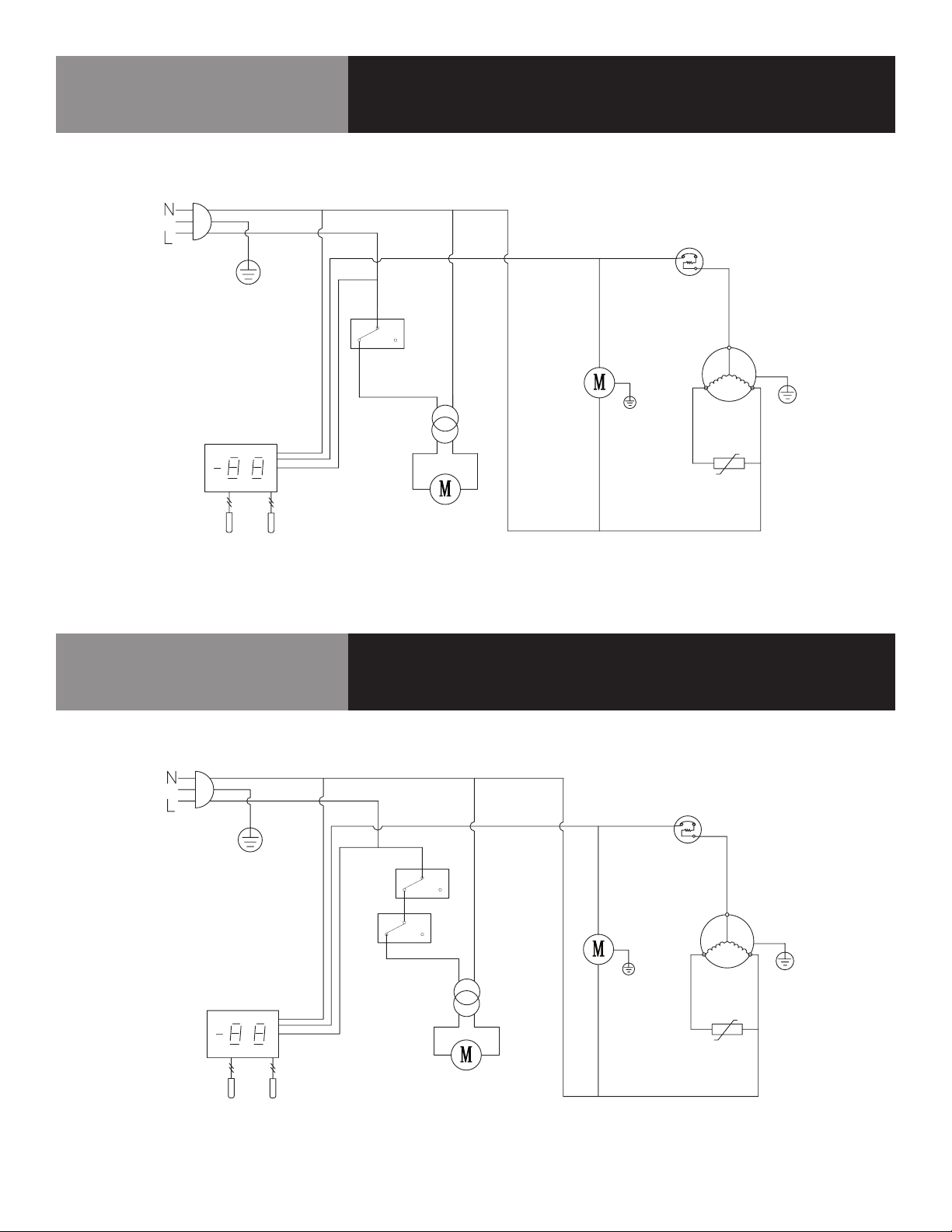
KCHUC27R / KCHUCWT27R / KCHUC27.2DR
LLAME A LA FÁBRICA SI NECESITA REPUESTOS:
866-738-1640
Diagrama de cableado
PLUG
THERMOSTAT DISPLAY
ROOM
SENSOR
KCHUC48R / KCHUCWT48R / KCHUC60R /
KCHUCWT60R
LLAME A LA FÁBRICA SI NECESITA REPUESTOS:
866-738-1640
EVAP
DOOR
SWITCH
FAN
POWER
EVAP
FAN
OVERLOAD
PROTECTOR
CONDENSEN
FAN
COMPRESSOR
PTC
STARTER
Diagrama de cableado
PLUG
THERMOSTAT DISPLAY
ROOM
SENSOR
6 MESAS DE PREPARACIÓN ALIMENTOS
EVAP
DOOR
SWITCH
EVAP
FAN
FAN
POWER
OVERLOAD
PROTECTOR
CONDENSEN
FAN
COMPRESSOR
PTC
STARTER
Page 31
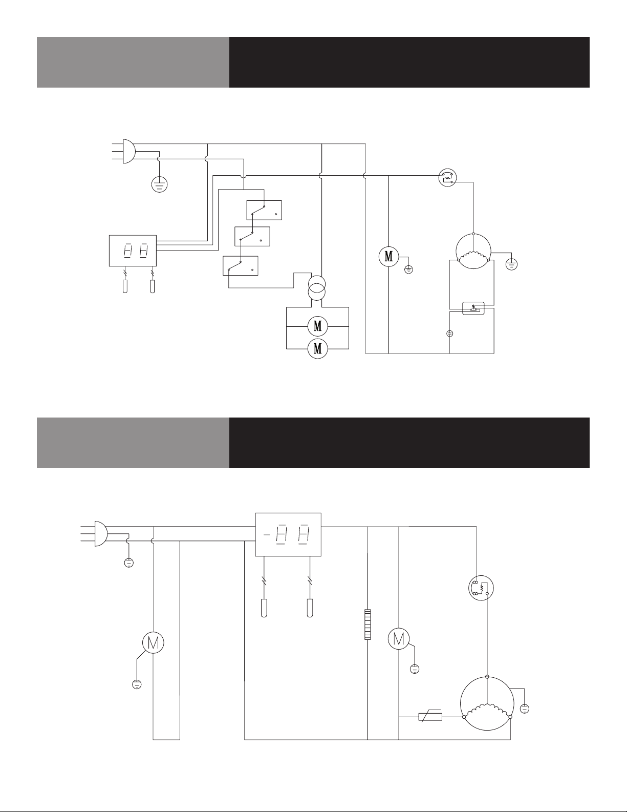
KCHUC72R / KCHUCWT72R
LLAME A LA FÁBRICA SI NECESITA REPUESTOS:
866-738-1640
N
L
Diagrama de cableado
PLUG
THERMOSTAT DISPLAY
ROOM
SENSOR
KCHPT50.6
LLAME A LA FÁBRICA SI NECESITA REPUESTOS:
866-738-1640
EVAP
EVAP
FAN
DOOR
SWITCH
OVERLOAD
PROTECTO R
CONDENSEN
FAN
FAN
POWE R
STARTING
CAPACITO R
COMPRESSO R
Diagrama de cableado
CURREN T
RELAY
N
L
PLUG
CIRCUITALION
FAN MOTO R
7 MESAS DE PREPARACIÓN ALIMENTOS
THERMOSTAT DISPLAY
ROOM
EVAP
SENSO R
CONDENSE R
FAN MOTO R
DOOR FRAME HEATER
t ˚C
PTC STARTER
OVERLOAD
PROTECTO R
COMPRESSOR
Page 32
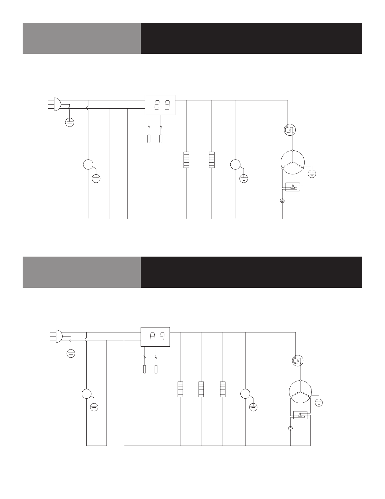
KCHPT60.9
LLAME A LA FÁBRICA SI NECESITA REPUESTOS:
866-738-1640
N
L
PLUG
Diagrama de cableado
THERMOSTAT DISPLAY
OVERLOAD
PROTECTOR
CIRCUITALION
FAN MOTOR
KCHPT70.12
LLAME A LA FÁBRICA SI NECESITA REPUESTOS:
866-738-1640
THERMOSTAT DISPLAY
ROOM
SENSOR
EVAP
CONDENSER
FAN MOTOR
MM
DOOR FRAME HEATER
MIDDLE FRAME HEATER
STARTING
CAPACITOR
Diagrama de cableado
COMPRESSOR
CURREN T
RELAY
N
L
PLUG
CIRCUITALION
FAN MOTOR
8 MESAS DE PREPARACIÓN ALIMENTOS
M
ROOM
SENSOR
EVAP
DOOR FRAME HEATER
MIDDLE FRAME HEATER
MIDDLE FRAME HEATER
CONDENSER
FAN MOTOR
M
STARTING
CAPACITOR
OVERLOAD
PROTECTOR
COMPRESSOR
CURRENT
RELAY
Page 33
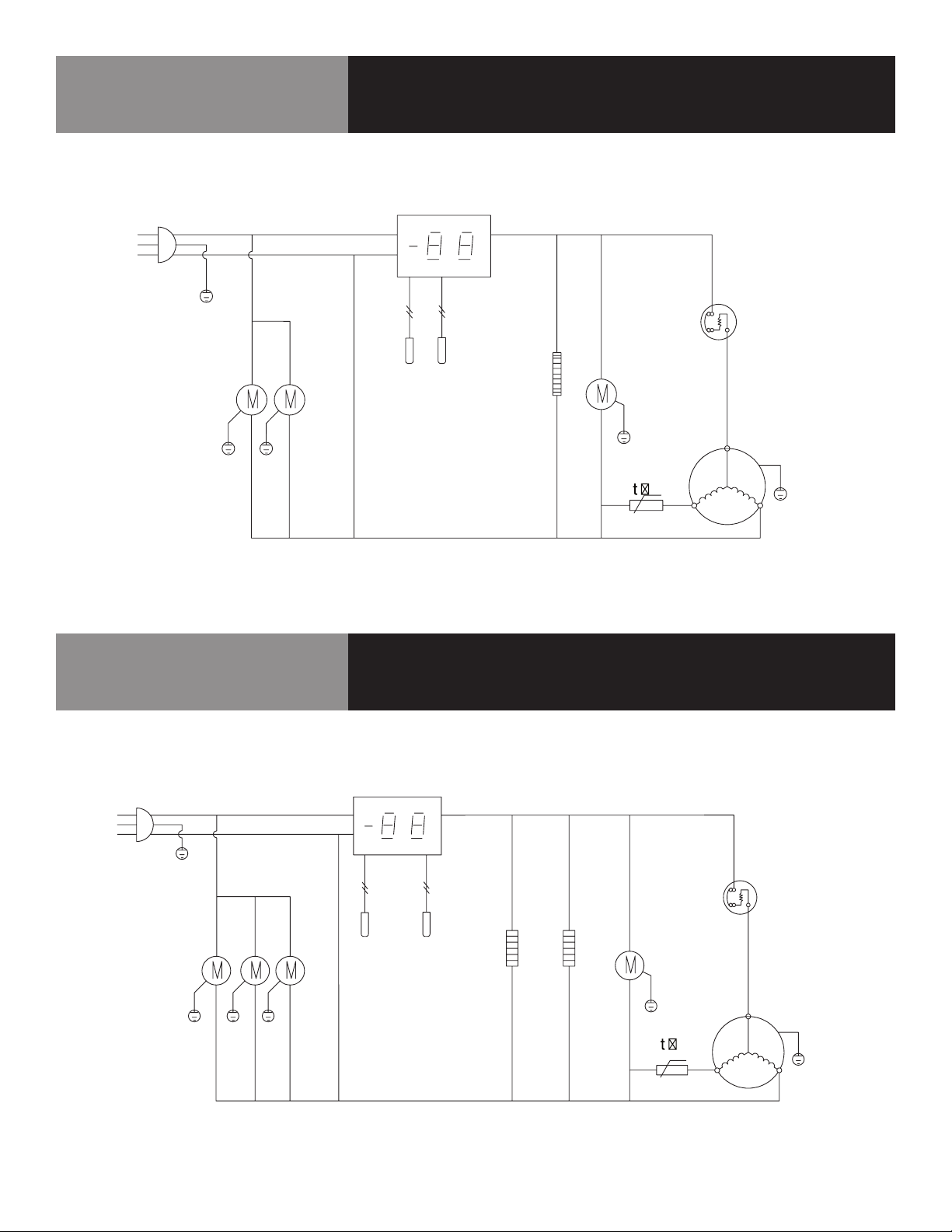
KCHST27.8 / KCHMT29.12 / KCHMT29.12.2D
LLAME A LA FÁBRICA SI NECESITA REPUESTOS:
866-738-1640
N
L
PLUG
Diagrama de cableado
THERMOSTAT DISPLAY
OVERLOAD
PROTECTOR
CIRCUITALION
FAN MOTOR
KCHST48.12 / KCHMT48.18 / KCHMT48.18.2D /
KCHST60.16 / KCHMT60.24 / KCHMT60.24.2D
LLAME A LA FÁBRICA SI NECESITA REPUESTOS:
866-738-1640
ROOM
SENSOR
THERMOSTAT DISPLAY
EVA P
CONDENSER
FAN MOTOR
DOOR FRAME HEATER
PTC STARTER
Diagrama de cableado
COMPRESSOR
N
L
PLUG
CIRCUITALION
FAN MOTOR
9 MESAS DE PREPARACIÓN ALIMENTOS
ROOM
SENSOR
EVAP
CONDENSER
FAN MOTOR
DOOR FRAME HEATER
MIDDLE FRAME HEATER
OVERLOAD
PROTECTOR
COMPRESSOR
PTC STARTER
Page 34
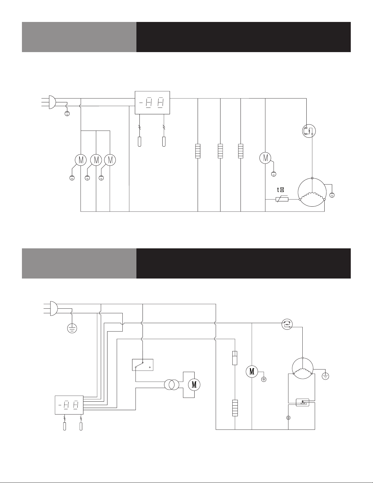
KCHST70.18 / KCHMT70.30
LLAME A LA FÁBRICA SI NECESITA REPUESTOS:
866-738-1640
THERMOSTAT DISPLAY
N
L
PLUG
Diagrama de cableado
OVERLOAD
PROTECTOR
CIRCUITALIO N
FAN MOTOR
KCHUC27F / KCHUCWT27F
LLAME A LA FÁBRICA SI NECESITA REPUESTOS:
866-738-1640
N
L
ROOM
SENSOR
EVAP
DOOR FRAME HEATER
MIDDLE FRAME HEATER
MIDDLE FRAME HEATER
Diagrama de cableado
CONDENSER
FAN MOTOR
COMPRESSOR
PTC STARTER
PLU G
THERMOSTAT DISPLAY
ROOM
SENSOR
10 MESAS DE PREPARACIÓN ALIMENTOS
EVAP
DOOR
SWITCH
FAN
POWE R
EVAP
FAN
THERMA L
CUT-OFF
DEFROST HEATER
OVERLOAD
PROTECTO R
CONDENSER
FAN
STARTING
CAPACITOR
COMPRESSO R
CURRENT
RELAY
Page 35
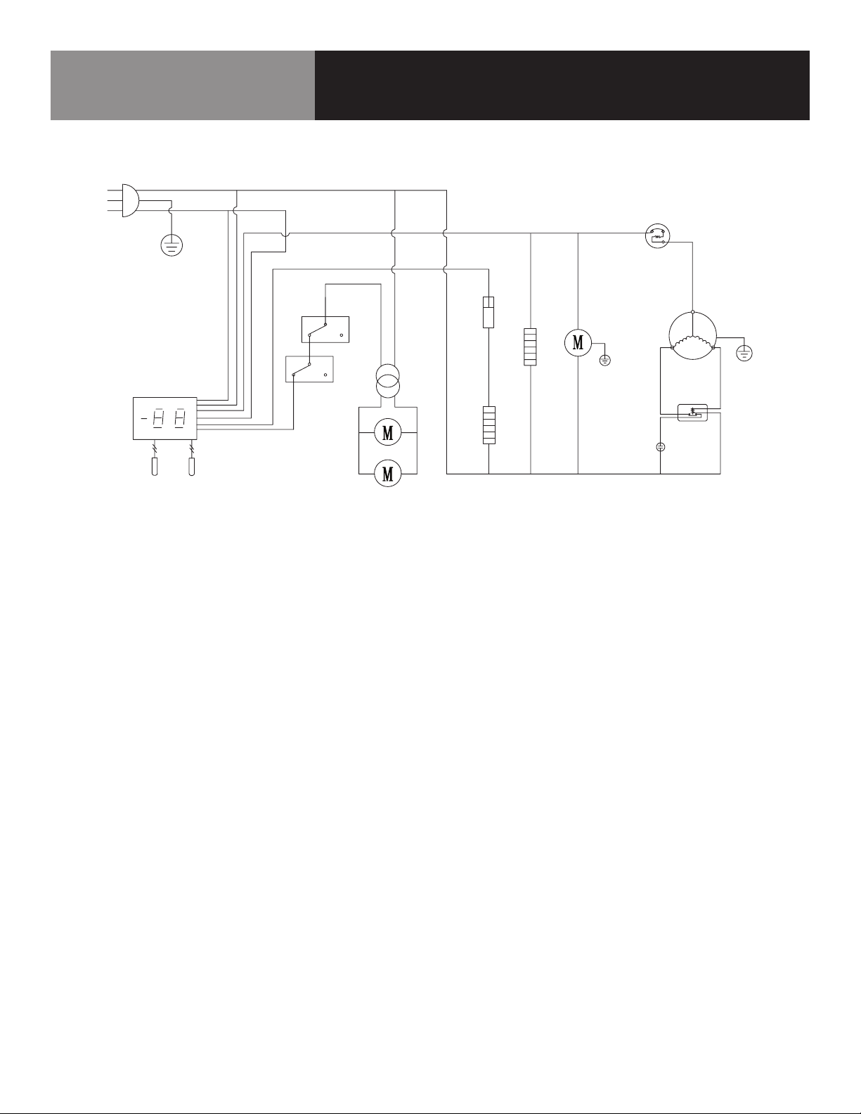
KCHUC48F / KCHUCWT48F
LLAME A LA FÁBRICA SI NECESITA REPUESTOS:
866-738-1640
N
L
Diagrama de cableado
PLUG
THERMOSTAT DISPLAY
ROOM
SENSOR
EVAP
DOOR
SWITCH
EVAP
FAN
FAN
POWER
THERMAL
CUT-OFF
DEFROST HEATER
OVERLOAD
PROTECTOR
CONDENSER
FAN
MIDDLE FRAME HEATER
STARTING
CAPACITOR
COMPRESSOR
CURRENT
RELAY
11 MESAS DE PREPARACIÓN ALIMENTOS
Page 36
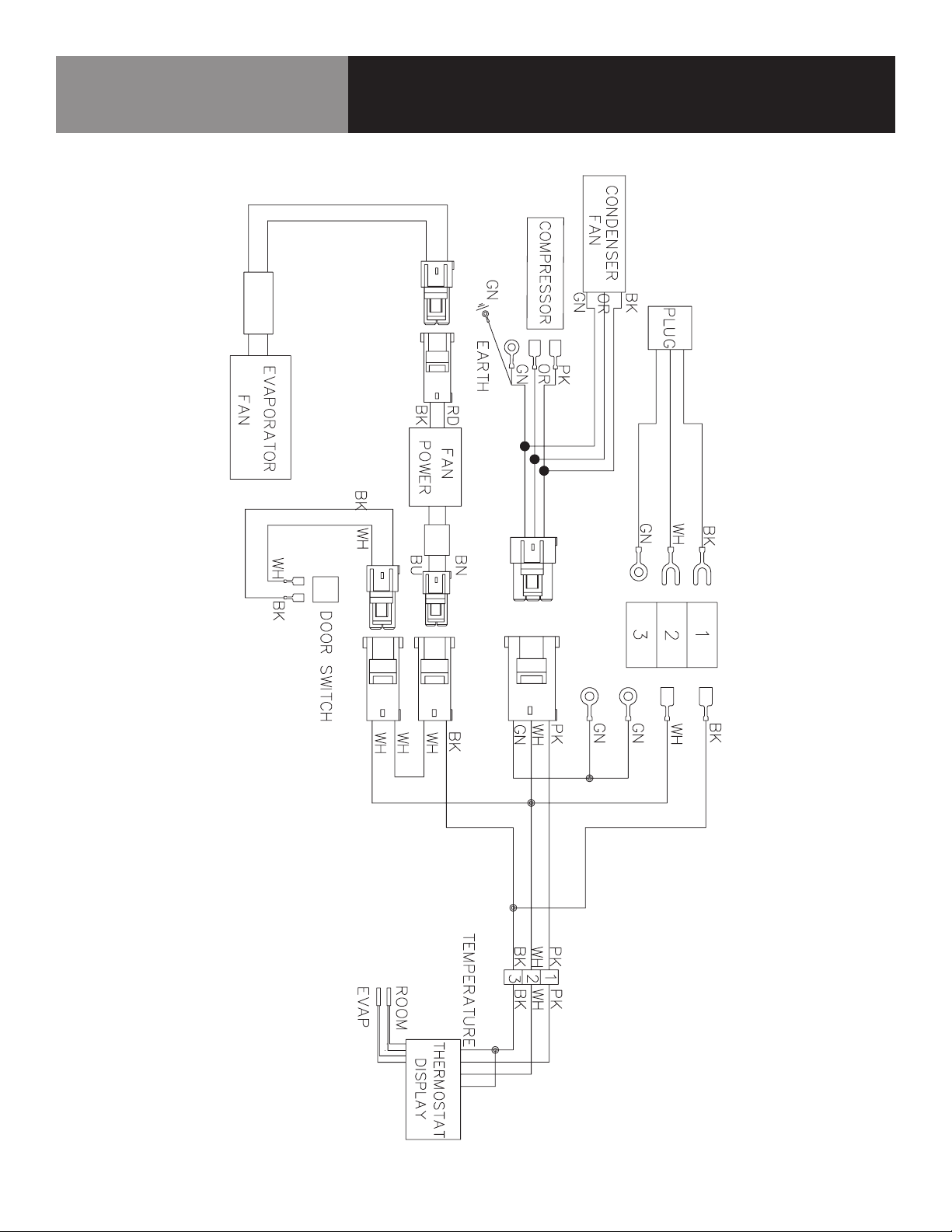
KCHUC27R / KCHUCWT27R / KCHUC27.2DR
LLAME A LA FÁBRICA SI NECESITA REPUESTOS:
866-738-1640
Diagrama de cableado
12 MESAS DE PREPARACIÓN ALIMENTOS
Page 37
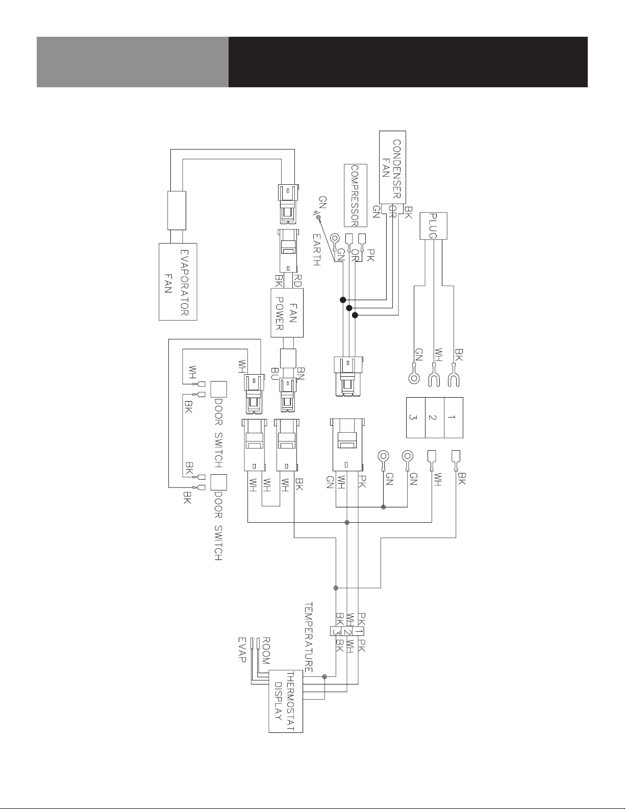
KCHUC48R / KCHUCWT48R / KCHUC60R /
KCHUCWT60R
LLAME A LA FÁBRICA SI NECESITA REPUESTOS:
866-738-1640
Diagrama de cableado
13 MESAS DE PREPARACIÓN ALIMENTOS
Page 38
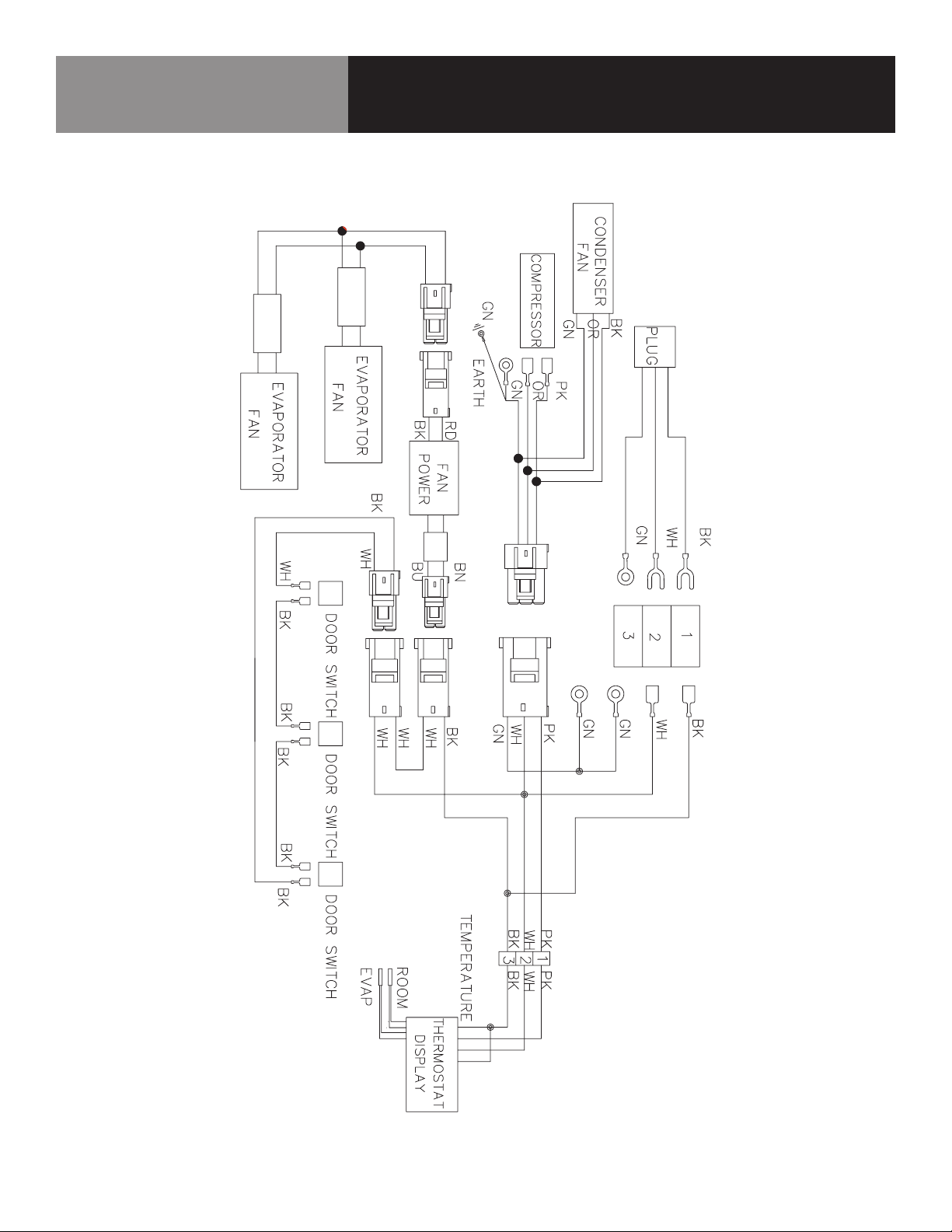
KCHUC72R / KCHUCWT72R
LLAME A LA FÁBRICA SI NECESITA REPUESTOS:
866-738-1640
Diagrama de cableado
14 MESAS DE PREPARACIÓN ALIMENTOS
Page 39
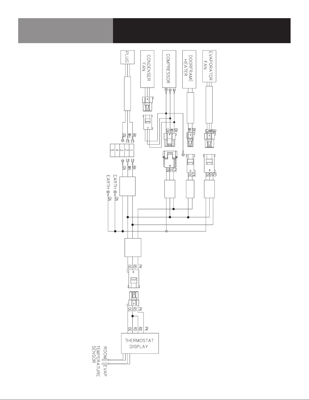
KCHST27.8 / KCHMT29.12 / KCHMT29.12.2D
LLAME A LA FÁBRICA SI NECESITA REPUESTOS:
866-738-1640
Diagrama de cableado
15 MESAS DE PREPARACIÓN ALIMENTOS
Page 40
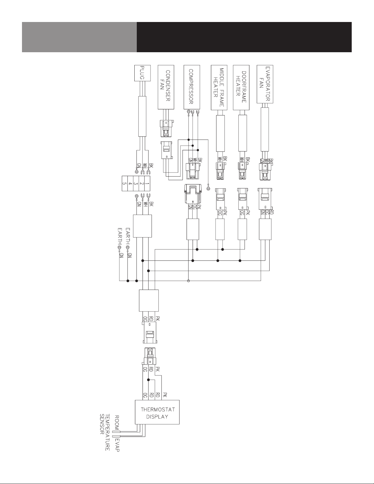
KCHST48.12 / KCHMT48.18 / KCHMT48.18.2D /
KCHST60.16 / KCHMT60.24 / KCHMT60.24.2D
LLAME A LA FÁBRICA SI NECESITA REPUESTOS:
866-738-1640
Diagrama de cableado
16 MESAS DE PREPARACIÓN ALIMENTOS
Page 41
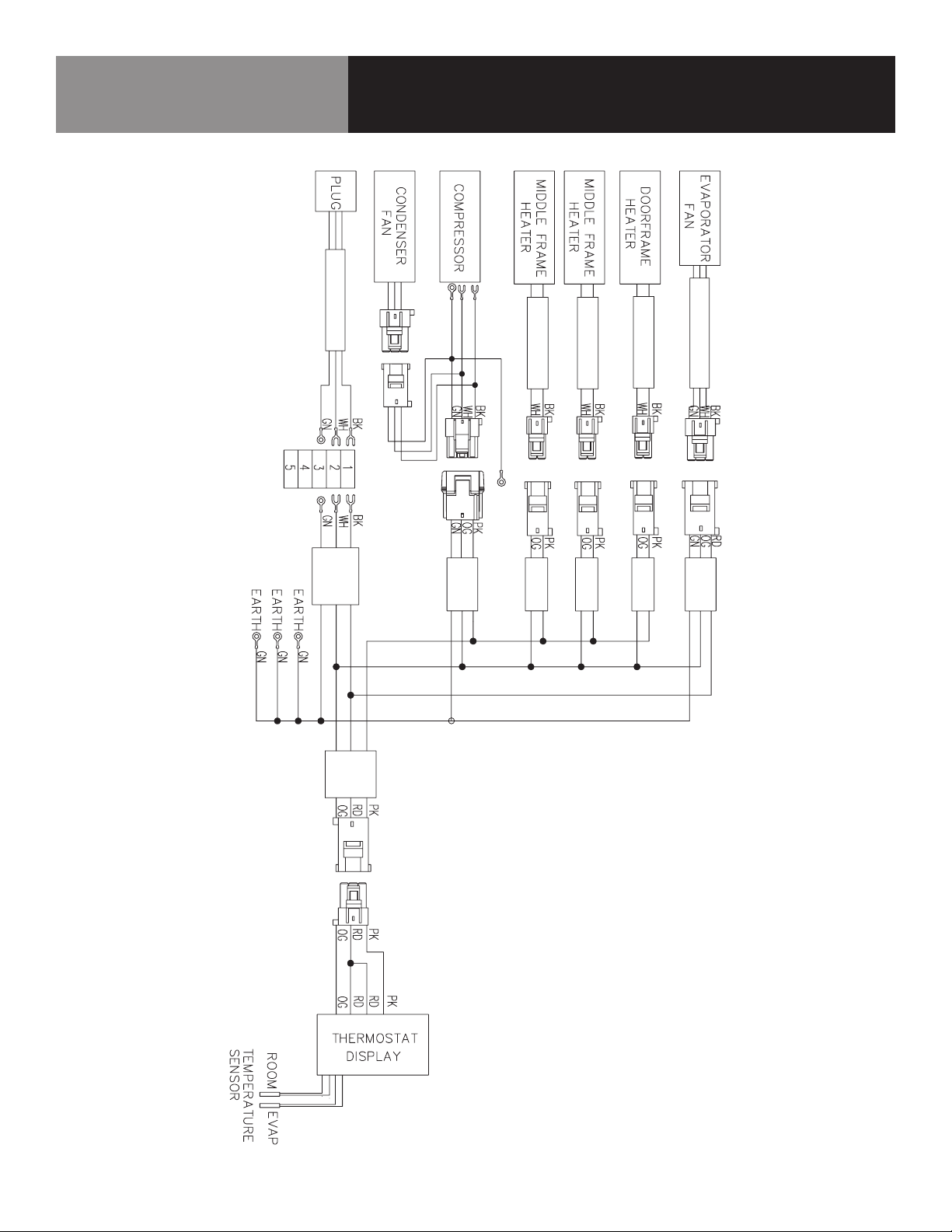
KCHST70.18 / KCHMT70.30
LLAME A LA FÁBRICA SI NECESITA REPUESTOS:
866-738-1640
Diagrama de cableado
17 MESAS DE PREPARACIÓN ALIMENTOS
Page 42
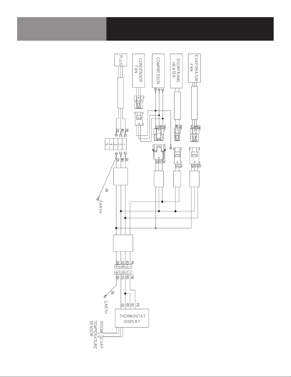
KCHPT50.6
LLAME A LA FÁBRICA SI NECESITA REPUESTOS:
866-738-1640
Diagrama de cableado
18 MESAS DE PREPARACIÓN ALIMENTOS
Page 43
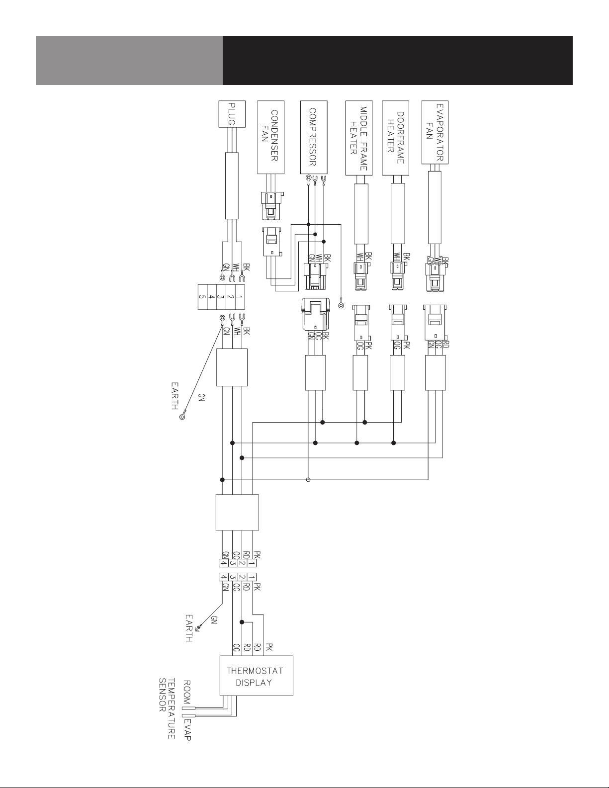
KCHPT60.9
LLAME A LA FÁBRICA SI NECESITA REPUESTOS:
866-738-1640
Diagrama de cableado
19 MESAS DE PREPARACIÓN ALIMENTOS
Page 44
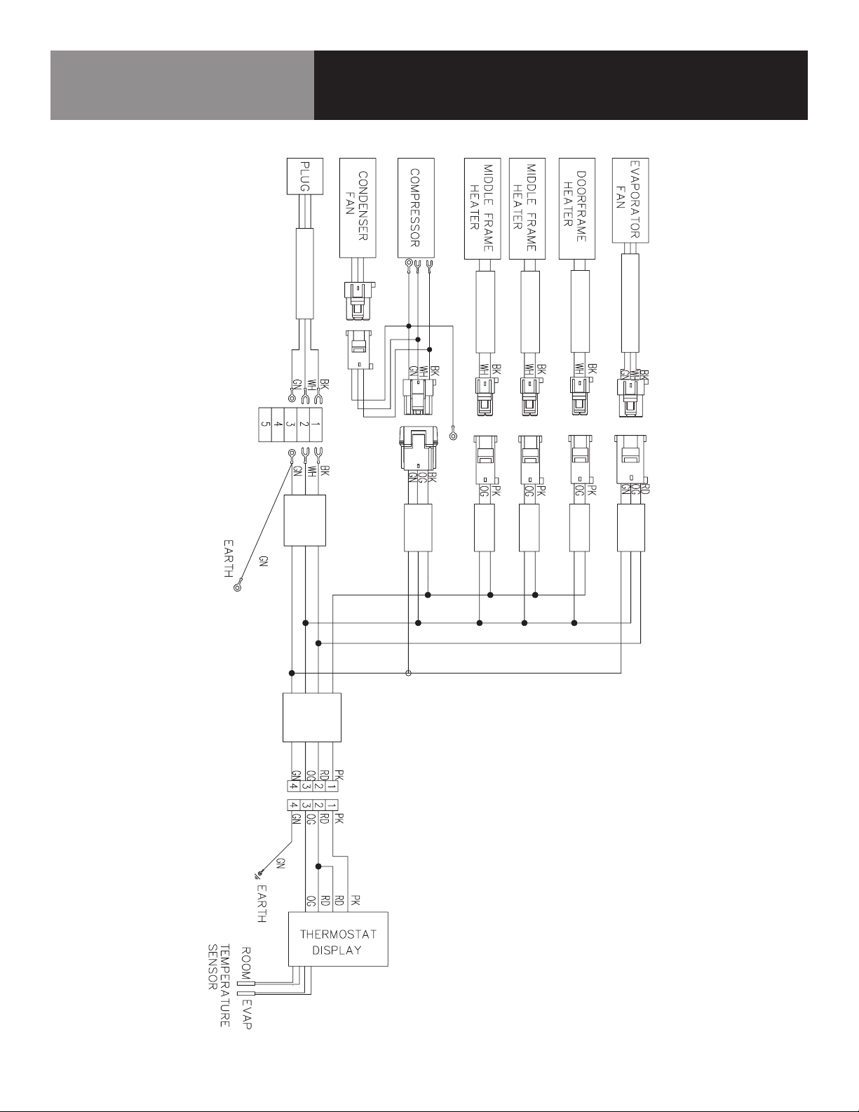
KCHPT70.12
LLAME A LA FÁBRICA SI NECESITA REPUESTOS:
866-738-1640
Diagrama de cableado
20 MESAS DE PREPARACIÓN ALIMENTOS
Page 45
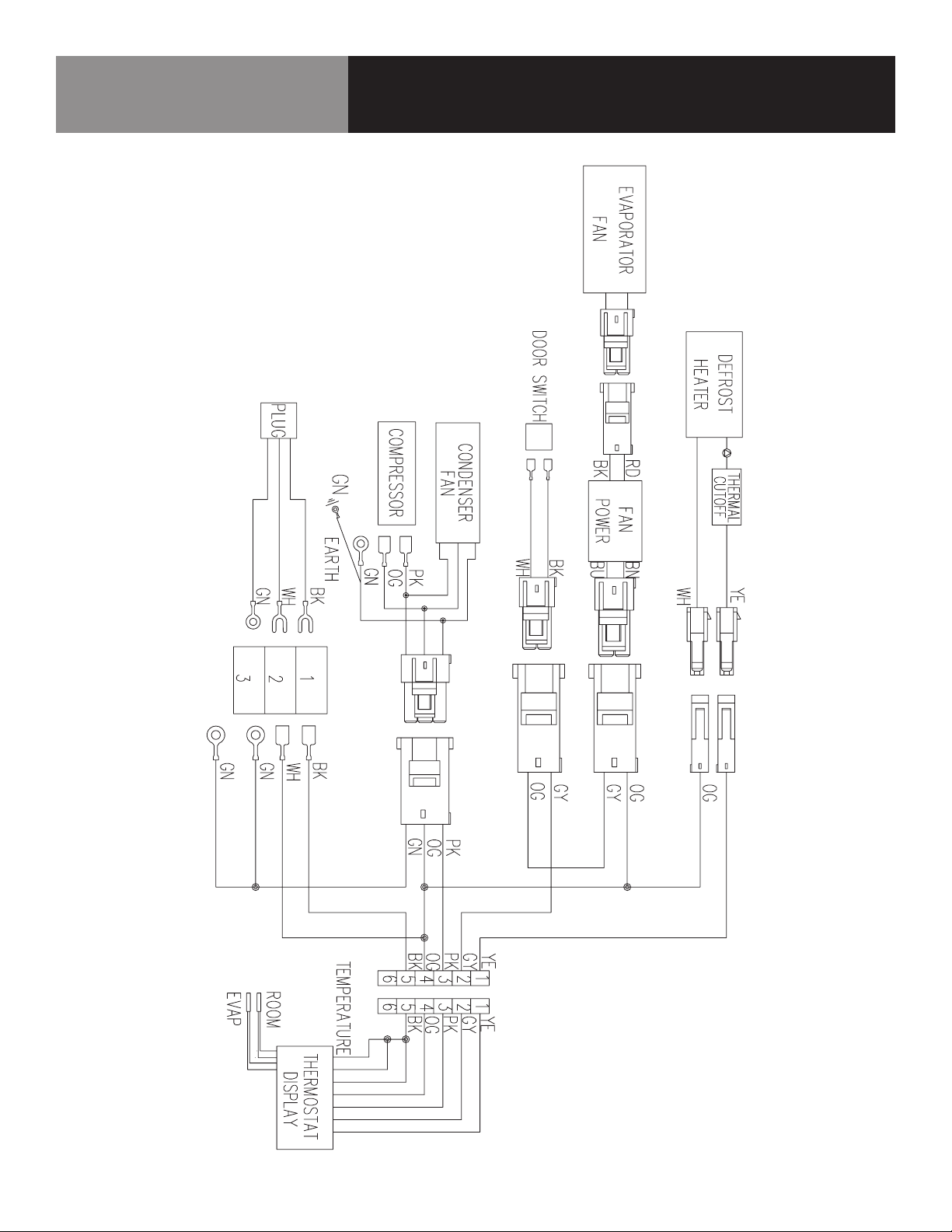
KCHUC27F / KCHUCWT27F
LLAME A LA FÁBRICA SI NECESITA REPUESTOS:
866-738-1640
Diagrama de cableado
21 MESAS DE PREPARACIÓN ALIMENTOS
Page 46
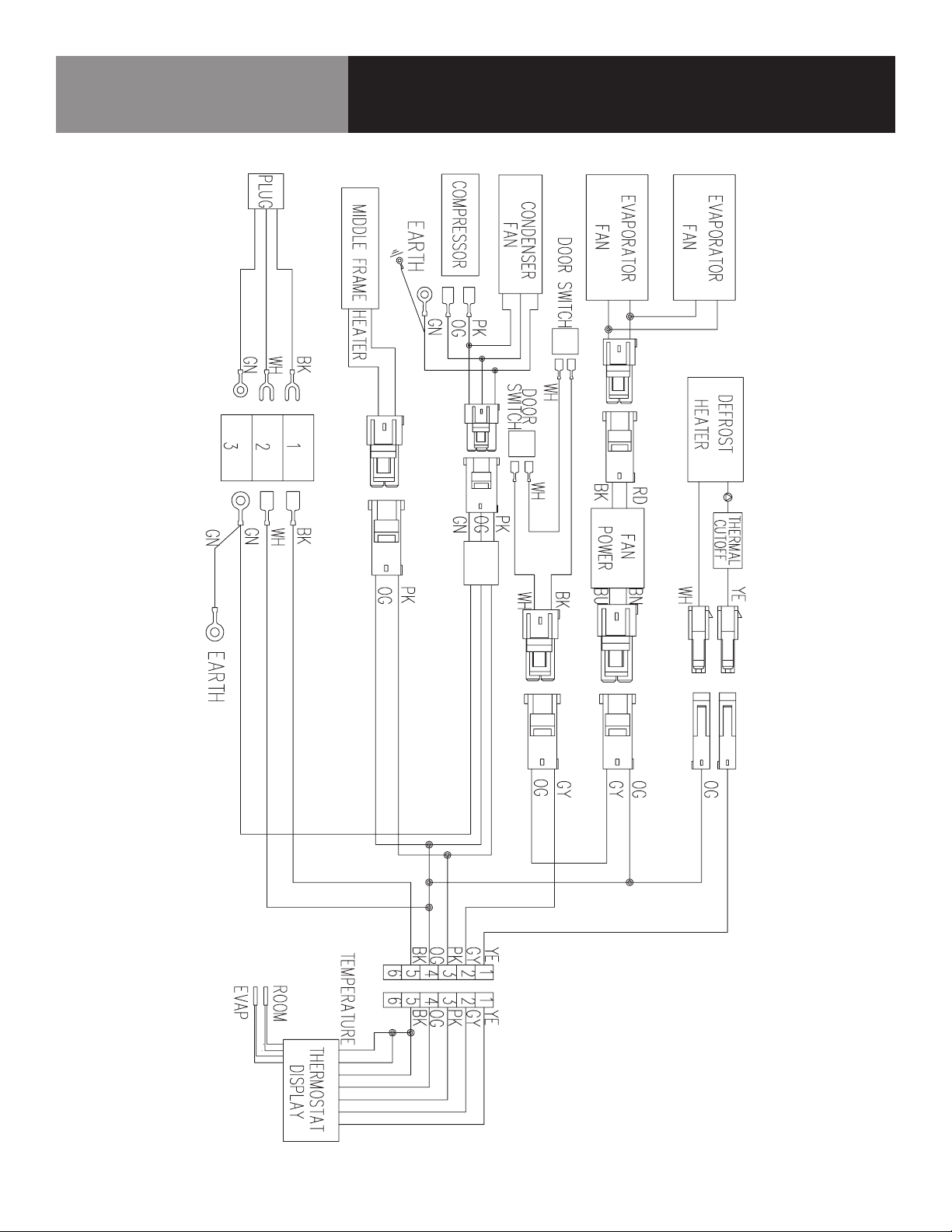
KCHUC48F / KCHUCWT48F
LLAME A LA FÁBRICA SI NECESITA REPUESTOS:
866-738-1640
Diagrama de cableado
22 MESAS DE PREPARACIÓN ALIMENTOS
Page 47

GARANTÍA
El equipo cuenta con garantía limitada de tres (3) años. Desde la fecha original
de compra y durante un periodo de tres (3) años, Electrolux Professional correrá con
todos los gastos, excepto los indicados más abajo, de reparación o sustitución de las
piezas de este equipo que muestren desperfectos de materiales o mano de obra en
el momento de la instalación, uso o mantenimiento, de acuerdo con las instrucciones
suministradas. Los equipos fabricados con compresor tienen una garantía adicional
de dos (2) años que solo se aplica al compresor.
EXCLUSIONES
ESTA GARANTÍA NO CUBRE LO SIGUIENTE:
1. Productos en los que el número de serie original se ha eliminado, alterado o no
pueda observarse con facilidad.
2. Desgaste normal y deterioro gradual.
3. Producto que ha sido transferido de su propietario original a otra parte o
trasladado fuera de EE.UU. o Canadá.
4. Óxido en el interior o el exterior de la unidad.
5. Productos adquiridos “tal cual”.
6. Pérdidas de alimentos debidas a desperfectos de nevera o congelador.
7. Daños sufridos en cualquier momento del transporte.
8. Llamadas al servicio técnico que no se refieran a desperfectos o defectos de
material o elaboración, o respecto a equipos utilizados de un modo distinto al
indicado en las instrucciones suministradas.
9. Llamadas al servicio técnico para corregir la instalación del equipo o para
solicitar instrucciones de uso.
10. Gastos para hacer accesible el equipo para su mantenimiento, como la retirada
de molduras, armarios, estantes, etc., que no formen parte del equipo cuando
se envía de fábrica.
11. Llamadas al servicio técnico para sustituir lámparas, filtros de aire, filtros de
agua y otros consumibles, o perillas, asas u otras piezas ornamentales.
12. Recargos derivados, entre otras cosas, de trabajo en horas extra, fin de semana
o festivos, peajes, trasbordos o kilometraje por llamadas al servicio técnico
desde zonas alejadas, incluido el Estado de Alaska.
13. Daños ocasionados al acabado del equipo o a su ubicación producidos durante
la instalación, entre otros, a pisos, armarios, paredes, etc.
14. Daños provocados por: servicios realizados por empresas de servicios no
autorizadas; uso de repuestos que no sean originales de Electrolux Professional
o repuestos obtenidos de personas que no sean empresas de servicios
autorizadas; o causas externas como uso incorrecto o indebido, alimentación
eléctrica inadecuada, accidentes, incendios o desastres naturales.
15. Los equipos utilizados por concesionarios o distribuidores en un remolque u otro
vehículo motorizado, o en distintas ubicaciones, tienen garantía de un (1) año
con limitación de piezas y mano de obra. Los equipos fabricados con compresor
tienen una garantía adicional de cuatro (4) años que solo se aplica al compresor.
EXCLUSIÓN DE GARANTÍAS IMPLÍCITAS; LIMITACIÓN DE RECURSOS
EL ÚNICO Y EXCLUSIVO RECURSO DEL CLIENTE SEGÚN LOS TÉRMINOS DE ESTA
GARANTÍA LIMITADA SERÁ LA REPARACIÓN O SUSTITUCIÓN DEL PRODUCTO SEGÚN
SE ESTIPULA EN EL PRESENTE DOCUMENTO. LAS RECLAMACIONES BASADAS
EN GARANTÍAS IMPLÍCITAS, INCLUIDAS LAS GARANTÍAS DE COMERCIABILIDAD
O DE IDONEIDAD PARA UN FIN DETERMINADO, ESTÁN LIMITADAS A UN (1) AÑO
O AL PERÍODO MÁS CORTO PERMITIDO POR LEY, AUNQUE NO INFERIOR A UN
(1) AÑO. EL GRUPO ELECTROLUX PROFESSIONAL NO SERÁ RESPONSABLE DE
DAÑOS CONSECUENTES O FORTUITOS COMO DAÑOS A LA PROPIEDAD Y GASTOS
OCASIONALES DERIVADOS DE CUALQUIER INCUMPLIMIENTO DE ESTA GARANTÍA
LIMITADA ESCRITA O DE CUALQUIER GARANTÍA IMPLÍCITA. ALGUNOS ESTADOS Y
PROVINCIAS NO PERMITEN LA EXCLUSIÓN O LIMITACIÓN DE DAÑOS ACCIDENTALES
O DERIVADOS NI LIMITACIONES ACERCA DE LA DURACIÓN DE LA GARANTÍA
IMPLÍCITA, DE MODO QUE ES POSIBLE QUE LAS LIMITACIONES O EXCLUSIONES
ARRIBA MENCIONADAS NO SE APLIQUEN A SU CASO. ESTA GARANTÍA ESCRITA LE
OTORGA DERECHOS LEGALES ESPECÍFICOS. ES POSIBLE QUE TAMBIÉN DISFRUTE
DE OTROS DERECHOS QUE VARÍEN DE UNA JURISDICCIÓN A OTRA.
Si necesita servicio
Para obtener servicio, la unidad debe registrarse primero en KelvinatorCommercial.
com. Una vez registrada, llame al 866-738-1640 para solicitar asistencia.
Esta garantía sólo se aplica en EE.UU. y Canadá y está garantizada por Electrolux
Professional Group SPA.
El Grupo Electrolux Professional no autoriza a persona alguna a cambiar o añadir
obligaciones a esta garantía. Las obligaciones de servicio y repuestos impuestas
por esta garantía debe satisfacerlas Electrolux Professional o una empresa de
servicios autorizada. Las características o especificaciones que se describen o
ilustran están sujetas a cambios sin previo aviso.
(Diciembre de 2018)
1-866-738-1640
Grupo Electrolux Professional, Norteamérica
23 MESAS DE PREPARACIÓN ALIMENTOS
Page 48
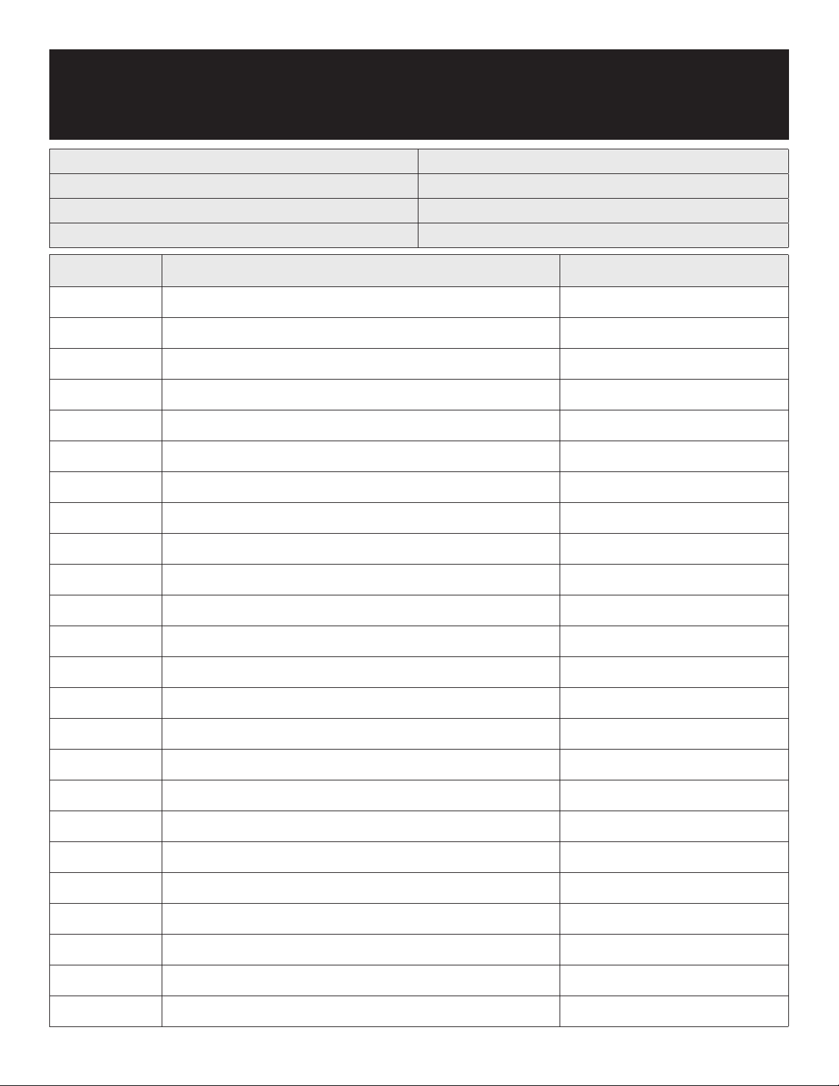
Registro de servicio
N.º de modelo: Adquirido a:
Nº de serie: Ubicación:
Fecha de compra: Fecha de instalación:
N.º de orden de compra: Para llamadas al servicio técnico:
Fecha Mantenimiento realizado Realizado por
24 MESAS DE PREPARACIÓN ALIMENTOS
 Loading...