

Kellys MTB Owner's Manual
OWNER'S

1
Dear customer,
thank you for purchase of KELLYS bicycle. We strongly encourage you to read the owner’s manual first
to enjoy your bicycle and for safety reasons too. By doing so, you will have a better understanding
for the general operation of your bike.
Your local KELLYS dealer will provide warrant y services and repairs of your bike.
TYPE OF BICYCLE USE
The bicycle is designed for use off-road on rough terrain, on public roads and on public pathways.
If you will ride your bicycle in road traffic mainly when reduced visibility you have to equip it with
lights and reflectors according relevant national law.
ADJUSTING SADDLE, STEM AND HANDLEBAR POSITION
All function parts of the bicycle are adjusted by manufacturer and checked by your local dealer
so you can safely use your bike immediately. The only thing you need to do is to set the saddle,
handlebar and stem position to provide yourself with maximum comfort and safe ope
ration of
brakes and steering of the bike.
SADDLE
SADDLE HEIGHT ADJUSTMENT
Take a seat on bicycle. Put your foot on pedal which is in the position nearest to the ground. Heel
must be on pedal. Leg must be stretched and slightly bent in the knee for reaching right height
of saddle. If you have saddle too high you will overcharge legs and back muscles. Knee and hips
muscle overcharge will be caused by too low levelled saddle.
ADJUSTING SADDLE POSITION AND TILT
Most recommended position of saddle is when saddle is parallel with ground. Try some positions of
saddle and finally choose the one which is the best for you. It is possible to move saddle forward
and backwards towards the handlebar. Tilt adjustment and moving of saddle is possible when screw
on lock of seat tube is released. Release the screw, move the saddle in desired position and set the
tilt and then tight
en screw to keep saddle safely in requested position. Make sure that the screw
is tightened properly.
IMPORTANT WARNING
There is the minimum insertion mark on the seatpost which marks minimal required
insertion depth of seatpost into bike frame. This minimal insertion mark of seatpost must
be invisible. Make sure that the minimum insertion mark of seatpost is not visible above the
bike frame after the seatpost is inserted into the frame. Seatpost clamp screw or seatpost
quick-release must be securely tightened so the seatpost is not turnable inside the frame.
Mov
e the lever of the quick-release to the sides only, to positions OPEN or CLOSE. Do not turn
locked quick-release lever, it could get damaged!
Recommended torque tightening values for seatpost tightening in bicycle frame:
Screw M4 - seatpost clamp screw on carbon composite bike frame 4,5 Nm
Screw M5 - seatpost clamp screw on aluminium alloy bike frame 6 Nm
Screw M8 - seatpost clamp screw 25 Nm
Recommended torque tightening values for seat tube lock screw:
Screw M5 10 - 12 Nm
Screw M6 12 - 15 Nm
Screw M8 20 - 25 Nm
STEM AND HANDLEBARS
STEM (A-HEAD TYPE STEM)
The a-head type of stem is fastened on fork neck and is fixed by 2 Allen screws. Height of stem
and handlebars is set by rings which are placed between stem and headset or eventually by stem
change for another with different angle. Allowance of headset is possible to set by stem. Release 2
Allen screws on stem clamp which lock stem to the fork and release screw on headset as well. Set
heads
et allowance by loosening or tightening of headset screw to make fork rotation easy. Do not
let headset to have its own allowance. At first tighten headset screw. Now set stem direction and
tighten stem by 2 Allen screws on stem clamp.
Torque tightening values:
Screw M4 for stem clamp 5 Nm*
Screw M5 for stem clamp 5 Nm*
Screw M4 for handlebars clamp 5 Nm*
*Recommended values must be kept if instruction on product does not vary.
STEM WITH THREAD
This kind of stem is plugged-in fork neck. It is secured by long screw and nut inside fork. Long screw
has shape of oblique frustum. Release long screw and slew the stem for stem level and direction
setting-up. In case that stem will not be released rap on screw by rubber hammer.
IMPORTANT WARNING
There is mark on the stem which shows maximal possible height of stem. This mark must be
invisible. Never post stem so high that this mark will be visible!
owner‘smanual
MTB
2
owner‘smanual
MTB
3
Torque tightening values:
Stem sleeve screw M6 20 Nm*
Handlebars sleeve screw M6 20 Nm*
*Recommended values must be kept if instruction on product does not vary.
BICYCLE MAINTENANCE
We would like to remind you to do a proper maintenance to keep your bike in a good condition.
Regularly check if all screws of your bike are properly tightened.
CRANKSET AND PEDALS
After the first 20 km tighten the crankset and also tighten the pedals to the crank arms. Check if
crank bolts are properly tightened. Check whether left crank arm screws are tightened firmly when
bottom bracket axle is integrated with right crank arm.
IMPORTANT WARNING
No check of crank arms fastening to the bottom bracket axle may result in progressive
release of crank arms and cause irreparable damage to the crank arm. Such damaged crank
arms must be replaced with new crank arms. Please contact special bike service for crank
arms replacement. Pedals must be firmly fastened in crank arms. Check tightness of pedal
fastening regularly otherwise pedals may release progressively an
d thread inside of crank
arm will be damaged. Above mentioned damages are not covered by warranty.
PEDALS ASSEMBLY
Pedals are generally marked on the axle of each pedal by letters R - right pedal and L - left pedal.
1. First lubricate the thread on pedals with grease before assembly.
2. Screw the right pedal (R) into the thread of the right crank arm (arm with chainwheels) by turning
it to the right.
3. Screw the left pedal (L) into the thread of left crank arm by turning it to the left.
4. Tighten firmly with
appropriate tool. Make sure that the shouldering of the pedal axis sits on
the crank arm.
WARNING
Clip-in pedals and pedals with toe clips or toe straps bond feet tightly with pedals which enables
higher pedalling efficiency. These pedals require usage of special cyclist shoes which are adapted
to clip-in mechanism.
Use of these pedals requires skills therefore it is recommended to train clipping-in and clipping-out
in safe place before
first ride.
BOTTOM BRACKET PARTS
Both cups of bottom bracket parts must be firmly tightened in the frame. Check them periodicaly,
mainly after ride in wet and muddy conditions. B.b.parts must rotate without any friction and loose
if not we advise you to contact a special bike service.
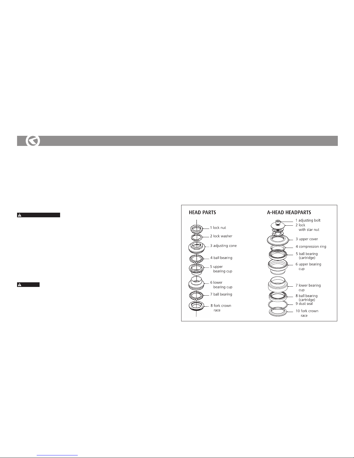
HEAD PARTS
Head par ts have to be sufficiently tightened and correctly assembled. If there is any loose in a head
parts, follow next steps:
1. Hold the adjustin
g cone (3) with the right wrench, and release the lock nut (1) with another
wrench.
2. Tighten the adjusting cone so there is no loose in the head parts, and fork is turning easily.
3. Hold the adjusting cone again, and tighten the lock nut to secure the head parts.
owner‘smanual
MTB
 Loading...