

Page 1
HigH AccurAcy Pressure TrAnsmiTTer
durAble wiTH indusTry sTAndArd AnAlog ouTPuTs And cusTom rAnges
The Valueline by Keller America provides standard features that far exceed those of comparably priced transmit-
ters by combining proven piezoresistive silicon sensor technology with Keller’s state-of-the-art signal conditioning
circuitry. The result is outstanding ±0.25% FS standard (±0.1% optional) Total Error Band (TEB)4 accuracy over a
wide compensated temperature range.
The ability of the Valueline to provide this level of sustained performance over a wide range of operating condi-
tions makes it ideally suited to pressure monitoring applications such as tank level measurement, pump control,
and VFD control. Plus, guaranteed lightning protection makes this transmitter ideal for installation in areas prone
to chronic damage due to transients caused by lightning.
For more information on the Valueline, or any other Keller product, please contact Keller America, or view the
entire Keller catalog at http://www.kelleramerica.com/datasheets.html.
FEATURES
NSF 61 / NSF 372 approved construction for use in drinking water applications
4...20mA models include guaranteed lightning protection at no additional cost.
16-bit internal digital error correction for cost-effective low Total Error Band (TEB)
316L stainless steel construction
2-year warranty covers defects in materials and workmanship.
Standard outputs simplify interface to controls, data collection, and telemetry systems.
Various electrical connections for easy integration into new and existing systems.
Cabled versions are rated IP68 and suitable for submersion.
Built in the U.S.A. ARRA Section 1605 Compliant.
Standard 3-day lead time.
4
VAlueline
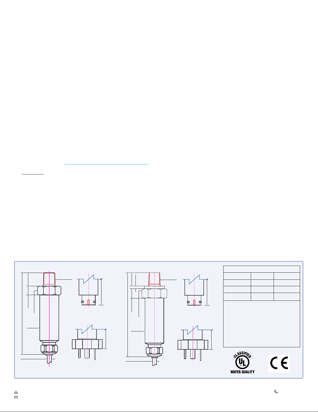
0.59 [15]
0.39 [10]
0.865 HEX [22]
Ø 0.825 [24]
Approx. 4.15 [105]
Ø 0.23 [5.8]
KELLER America Inc.
Newport News, Virginia
www.kelleramerica.com
sales@kelleramerica.com
Ranges ≤ 450 PSI
1/4”-18 NPT
Dimensions in inches [mm]
Ranges ≥ 450 PSI
0.12 [3]
0.59 [15]
Approx. 4.1 [104]
MIL-C 26482 MIL-C 26482
Approx. 3.8 [97]
DIN43650
0.41 [10.5]
0.945 HEX [24]
Ø 0.825 [24]
Approx. 4.25 [108]
Ø 0.23 [5.8]
1/4”-18 NPT
DIN43650
Wiring
2-wire (mA) 3-wire (VDC)
Pin 1 / C / White OUT / GND GND
Pin 2/ B / Red N/A +OUT
Pin 3 /A / Black +Vcc +Vcc
Approx. 4.2 [107]
Pins 1,2,&3 refer to the DIN and mPm-style connectors. A, B, C refer to the MIL style connector, and
colors correspond to cable conductors.
Braided shield wire connected to transmitter
housing. For lightning protection to function properly
(4-20 mA only) the shield wire must be connected to
a good earth ground.
Specications are subject to change without notice.
Approx. 3.9 [990]
Edition 03/2019
Subject to alterations
877-253-5537
757-596-6659
Page 2

Pressure Ranges
1,2,3
Relative Innite between 0...2 to 0...450 PSIG
Absolute Innite between 0...2 to 0...450 PSIA
Sealed Innite between 0...500 to 0..15,000 PSIS
Proof Pressure 10X for 1 PSI to 1.1X for 15k PSI
1. PSIG = Gage; Zero-point referenced to local atmospheric pressure.
PSIA = Absolute; Zero-point set at hard vacuum.
PSIS = Sealed Gage; Zero-point set at 1 bar absolute (14.504 PSIA).
2. Zero-point can be suppressed or elevated for special applications.
3.Intermediate ranges are realized by deranging the analog output from the next highest basic range:
1, 3, 10, and 30 bar (relative) 1, 3, 10, and 30 bar (absolute), and 100, 300, and 1000 bar (sealed).
Pressure range may be specied in units of lb/in2(psi), inches WC or feet WC. Keller America uses the
International Standard conversion of 2.3067 feet WC/psi.
Accuracy
4
Static Standard ±0.1% FS, Optional ±0.05% FS
Total Error Band Standard ±0.25% BR, Optional ±0.1% BR
4. Static accuracy includes the combined effects of non-linearity, hysteresis, and non-repeatability
at room temperature (25°C). Total Error Band (TEB) includes the combined effects of non-linearity,
hysteresis, and non-repeatability as well as thermal dependencies, over the compensated temperature
range, expressed as a percentage of the basic range (BR).
The calculation for maximum TEB on intermediate ranges (IR) is:
TEBIR = (BR/IR) X TEB
BR
Output
Current 4...20mA
Voltage 0...5 VDC
0...10 VDC
Connection
Process 1/4”-18 NPT Male
5
Electrical std. 10 ft. Cable
DIN43650
mPm393
MIL-C 26482
5. Other process connections available on request. Consult the factory.
6. Mating connector supplied at no extra cost.
7. At extra cost, includes mating connector.
6
6
7
Electrical
8
Supply (4-20mA) 11...28 VDC
Supply (0-5VDC) 8...28 VDC
Supply (0-10VDC) 13...28 VDC
Load Resistance (mA) <(Supply-11V)/0.022A
Load Resistance (VDC) >4k ohm
8. Nominal values may be higher depending upon cable length. Internal lightning protection increases
the minimum-required supply voltage from 8VDC to 11VDC, due to internal resistance of the surge
protectors. In addition, cable resistance (~70Ω / 1000ft) adds to the supply requirement. In order to
insure proper system operation, calculate the minimum required supply voltage (at the source) as
follows:
For two-part (internal+external) system (recommended):
MINIMUM SUPPLY VOLTAGE = 11.6 + 0.022 (CABLE LENGTH x 0.07) VDC
For internal only protector (standard with 4-20mA output):
MINIMUM SUPPLY VOLTAGE = 11 + 0.022 (CABLE LENGTH x 0.07) VDC
Certications
CE EN50081-1, EN50082-2
Shock 20g (11ms)
Vibration 20g (5-2KHz, max. amp ±3mm per IEC68-2-6)
NSF / ANSI 61, 372
Environmental
Protection Rating
Cable IP68
mPm393 IP65
DIN43650 IP65
MIL-C 26482 IP65
Operating Temp. -10...60° C (Cable)
-30...100° C (Connector)
Compensated Temp. -10...80° C
Wetted Materials 316 L Stainless Steel
Optional Accessories
1/2” NPT Conduit Fitting Drying Tube Assembly Bellows Assembly Termination EnclosureProcess Meter Signal Line Surge Protector
KELLER America Inc.
Newport News, Virginia
www.kelleramerica.com
sales@kelleramerica.com
Edition 03/2019
Subject to alterations
877-253-5537
757-596-6659
 Loading...