

Page 1
Content MeasureMent systeM
86 mm
53 mm
Ø 21 mm
60 mm
7 mm
12mm
6kt – SW 17
USIT-Ring
G1/4’’
Ø 21 mm
10500
KELLER
98 mm
64 mm
Air-Pressure On-Button
Ø 9,2 mm / Ø 8,6 mm
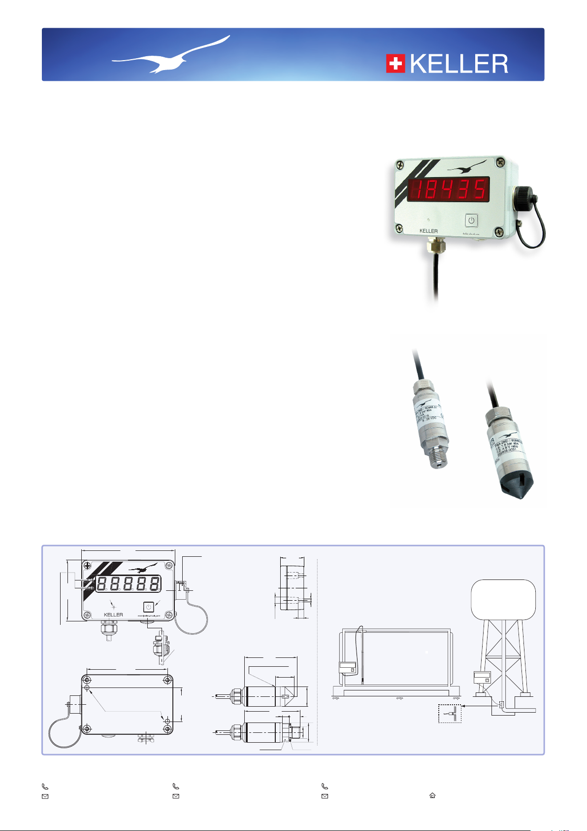
for ventilated or pressurised tanks
Castello offers a user-friendly way to re present the pressure measurement at the bottom of a
tank as the quantity of remaining liquid. At the push of a button, the micro -controller performs
the calculations using the information of the tank shape and dimen sions and displays the remaining tank content quantity on the clearly legible 5-digit LED display in the desired unit (litres,
gallons etc.).
The unit is congured using a PC and the easy-to-use software so that the lling level, which
determines the pressure, can be converted into an appropriate lling quantity. First the tank
shape is selected, then the tank dimensions and the specic gravity of the liquid are entered. It
contains the most current tank shapes. The program covers the most common tank shapes, but
also enables any shape by entering the parameters into a specied table.
The exclusive use of absolute pressure sensors in the Castello system eliminates the use of
capillary vented cables with all the problems associated with a gauge pressure measurement.
The Castello housing integrates an air pressure sensor, ranged between 0,8 bar and 1,2 bar
absolute. The sensors to measure the hydrostatic pressure at the bottom of the tank are calibrated from 0,8 to 1,8 bar abs for tanks up to 5 m in height, and 0,8 to 2,3 bar abs for tanks up to
10 m in height. The pressure difference, calculated by the
static pressure.
The content of a pressurised tank is determined using the difference between the measurements from two absolute pressure sensors located at the top and bottom of the tank.
The overall accuracy of the system of 2 mbar is achieved using a computerised calibration
and compensation procedure for the pressure sensors. The coefcients for this calculation are
stored in EEPROMs in the sensors. These are retrieved by the micro processor at each mea-
surement and employed within the equations to calculate the pressure values. The Castello
housing and hydrostatic sensor can be interchanged at will.
It is also possible to connect a standard 3-wire transmitter or high-precision digital transmitter
(Series 36 X) that can be congured to an accuracy of 0,02 %FS over a range of 0 to 50 °C, a
true representation of which is displayed by the Castello.
The power supply to the system (8 to 28 V) can be provided externally or internally using a
9 V battery. The display is obtained by pressing the button on the front, and the value appears
for a congurable duration. The Castello has two switch outputs with congurable functiona lity
and threshold values. An external power supply must be provided if the switch outputs are used.
micro -controller
, is the relative hydro-
Castello
CA1
Series 23 Q
Series 26 Q
Indication of
switching outputs (LED)
Bottom View
Drill holes for mounting
KELLER AG für Druckmesstechnik
CH-8404 Winterthur
+41 52 235 25 25
info@keller-druck.com
Binder male socket
8 pole / Serie 723
Pin connection
1: +S1 (Relayoutput)
2: -S1 (Relayoutput)
3: +S2 (Relayoutput)
4: + VCC (8…28 VDC)
5: RS 485 A
6: -S2 (Relayoutput)
7: RS 485 B
8: GND
34 mm
Side View
Optional:
second transmitter
Diaphragm’s position
20 mm
36 mm
KELLER Ges. für Druckmesstechnik mbH
DE-79798 Jestetten
+49 7745 9214 0
eurocenter@keller-druck.com
Mounting Options
Ø 4,8 mm
8
KELLER America
Newport News, Virginia
1 877 253 5537
sales@kelleramerica.com
Series 26 Q
10500
KELLER
/ / / / / / / / / / / / / / / / / / / / / / /
Series 23 Q
Edition 04/2018
Subject to alterations
Companies approved to ISO 9001
www.keller-druck.com
Page 2
Installation
There are two holes in the housing for mounting the unit. To install the sensor, unscrew and remove the cover of the unit, lead the cables through
the PG screw connections and attach the wires to the screw terminals. The Castello is programmed via the connector on the side, which is also
the location of the external power supply and switch output connections. Provided that the cover and the cable leadthrough are securely tightened,
the extremely robust housing is watertight in compliance with IP65.
Castello Ordering Information
Castello basic unit + KELLER standard transmitter series 23 Q (with thread) or series 26 Q (for lling level)
+ converter K-107 (serial) or K-104B (USB) for conguration incl. adapter (5-pin --> 8-pin)
or conguration in accordance with customer specications
Specications for Castello
Measuring / Pressure Ranges 5 m tank level (10 m standard cable): Range 0,8…1,8 bar abs.
10 m tank level (15 m standard cable): Range 0,8…2,3 bar abs.
Supply External: 8…28 V
Internal: 9 V battery
Switch outputs 2 pcs. PhotoMOS-Relais 40 V / 0,4 A
Battery Life
4’000 Measurements (display 10 seconds on)
6’000 Measurements (display 5 seconds on)
Interface RS485
Air Pressure Probe Level Probe
Temperature Range -20…+70 °C 0…50 °C
Accuracy (Error Band) max. 0,5 mbar
2 mbar (1,8 bar range)
3 mbar (2,3 bar range)
Indicator 5 digits – 14 mm high
7 segments LED
Resolution Min. 2’000 Points
Indicator Material Aluminium
Level Probe Material Stainless Steel AISI 316L
Cable Type Hytrel, 4,60 mm Ø
Probe Protection IP 68
Indicator Protection IP 65
Probe Certication II 1 G EEx ia IIC T6
LCIE 02 ATEX 6124 X
Indicator Certication In Progress
Overpressure 2 x Nominal Range
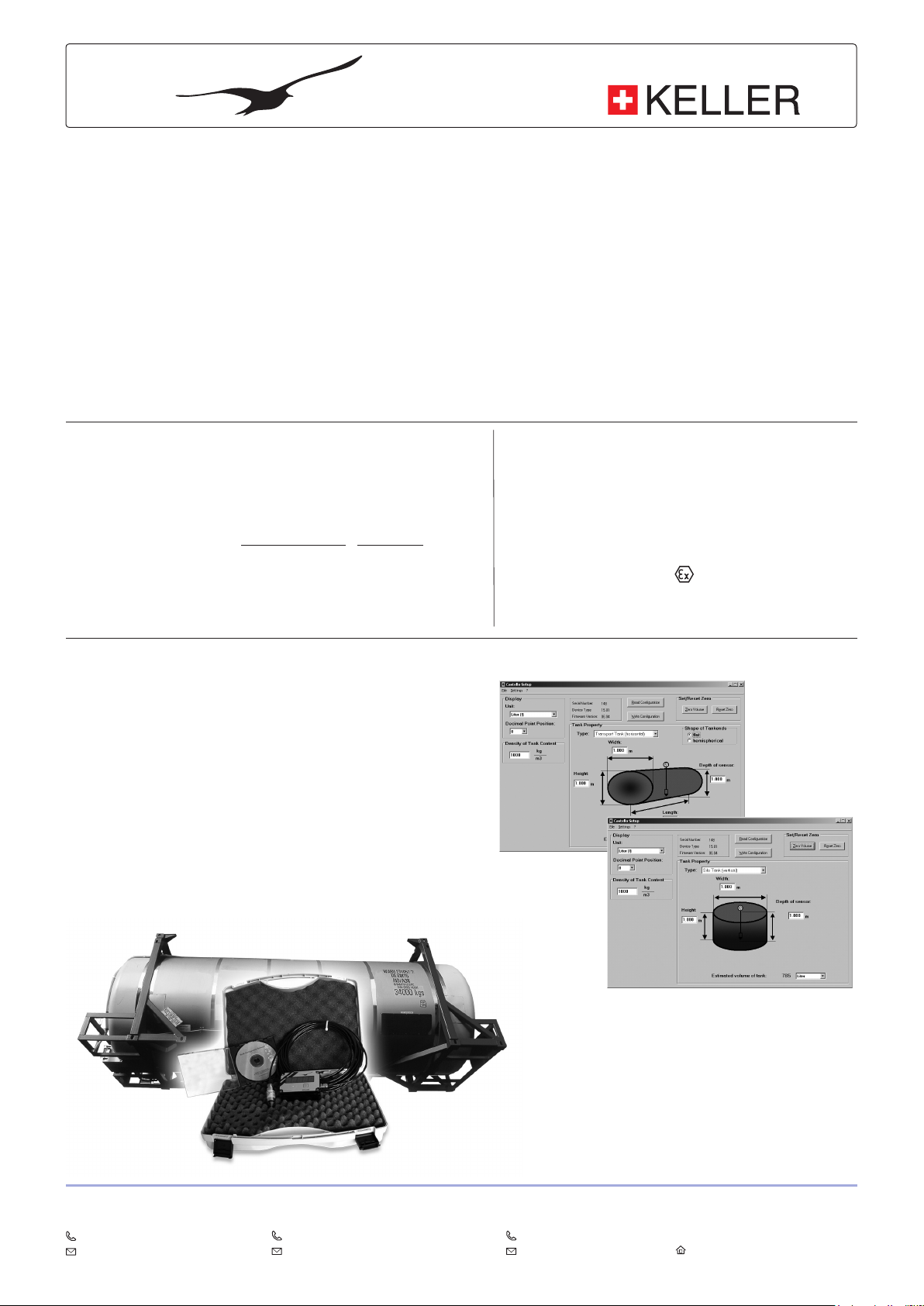
Conguration PC-Software
The software to congure Castello can be downloaded from our website or
ordered on CD for a handling charge. Castello can be connected to the PC
via KELLER converter cable K-107 or K-104B with adapter. Castello can be
congured for standard or EEPROM transmitters.
The software contains the pressure/content curves of the featured tanks.
The dimensions of the tank of a certain shape and the specic gravity of the
liquid is entered and the measurement unit for the display chosen.
The software also foresees the application for free standing water towers,
where the distance of the tank to the position of the transducer can be
chosen.
Options (extra charge):
–
Face plate with various measuring units and
customer’s logo
– Other housing colours (default: grey)
– Carrying case
– Factory conguration: foil strip on rear con-
taining all application-related details
– Wireless transmission via ARC-1
KELLER AG für Druckmesstechnik
CH-8404 Winterthur
+41 52 235 25 25
info@keller-druck.com
KELLER Ges. für Druckmesstechnik mbH
DE-79798 Jestetten
+49 7745 9214 0
eurocenter@keller-druck.com
KELLER America
Newport News, Virginia
1 877 253 5537
sales@kelleramerica.com
Edition 04/2018
Subject to alterations
Companies approved to ISO 9001
www.keller-druck.com
 Loading...