

Page 1
AA1510 / AA1510CA
Installation Instructions
FAILURE TO COMPLY WITH ALL INSTRUCTIONS MAY RESULT IN SERIOUS INJURY
Instrucciones de instalación
NO CUMPLIR TODAS LAS INSTRUCCIONES PODRÍA RESULTAR
EN LESIONES GRAVES
Instructions d’installation
LE NON-RESPECT DE CES INSTRUCTIONS PEUT ENTRAÎNER
UNE BLESSURE GRAVE
Page 2

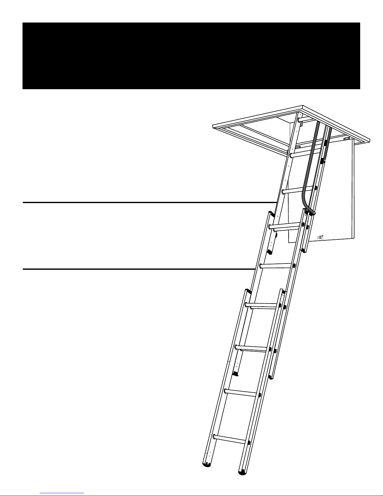
Compact Attic Ladder
ALUMINUM
BUILT FOR SMALL ATTIC OPENINGS
Table of Contents
Before you begin 2
Important questions 3
Step 1 Assembling the ladder 3
Step 2 Fitting additional top stops 4
Step 3 Fitting bottom stops 5
Step 4 Installing the ladder 5
Page
Step 5 Installing the assist arm 6
Step 6 Handrail assembly 7
Step 7 Finishing opening for door 7
Step 8 Hanging the door 8
Step 9
Step 10 Attaching the location bracket 9
Step 11 Operating the ladder 10
Appendix Creating a rough opening 11
Section 1.1 Important questions 11
Section 1.2 Tools and materials needed 12
Section 1.3 Finding a suitable location 13
Section 1.4 Cutting a hole in the ceiling 14-16
Locating the hole for the door
latch
8-9
Section 1.5 Framing the rough opening 16-19
Page 3
Before you begin
TOOLS REQUIRED
STEPLADDER
AWL
SAW
DRILL PLUS 1/2" & 1/16" BIT
LARGE FLAT SCREWDRIVER
PHILLIPS SCREWDRIVER
(small and medium)
ADJUSTABLE WRENCH/PLIERS
TAPE MEASURE/RULER
HAMMER
PENCIL
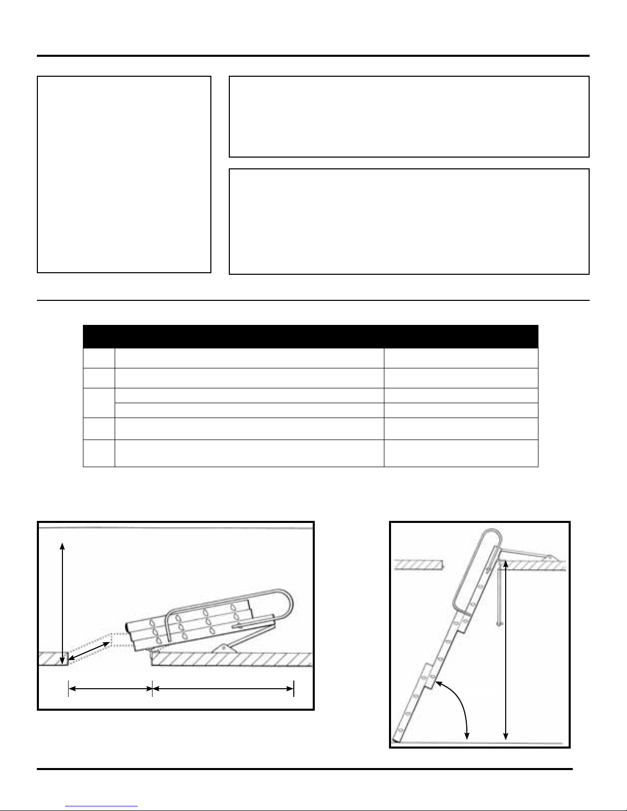
A Minimum Finished Opening (Length) 21"
B Minimum Finished Opening (Width) 15"
DOOR MATERIAL REQUIRED
BE SURE TO USE 3/4" CABINET GRADE PLYWOOD.
1 x 3 SOLID WOOD BOARD REQUIRED FOR DOOR FRAME
1 X 2 SOLID WOOD BOARD REQUIRED FOR DOOR JAM
AT THE BEGINNING OF EACH STEP THROUGHOUT
THIS INSTRUCTION MANUAL, FASTENERS AND
COMPONENTS THAT ARE NEEDED WILL BE LISTED.
IF ANY PARTS ARE MISSING OR BROKEN,
PLEASE CALL CUSTOMER SERVICE AT 1-888-523-3370.
Compact Attic Ladder
C
D* Minimum Stowing Height Required In Attic 28"
E**
Maximum Height 9' 10"
Minimum Height 7'
Minimum Length Required
Behind Rough Opening
44"
Closed Requirements Opened Requirements
D*
B
E**A
68°- 80°
C
*At handrail low position - 28"
At handrail top position - 38"
**At handrail low position - 44"
At handrail top position - 54"
2
Page 4

Important Questions
Read instructions completely before beginning. This is necessary to ensure that you have a suitable location for the attic
ladder and the ability to safely and properly install it.
Are you capable of installing this attic ladder?
To install this attic ladder you should have sawing, squaring, and aligning skills similar to those required to install a
window or a door frame. If you do not have these skills you should hire a professional carpenter to install this unit
(see the Yellow Pages under “Building Contractors, Carpenters, Home Builders, Home Improvements, or
Contractors-General”).
Does this attic ladder meet your needs?
This attic ladder is for residential use only. Installing this attic ladder in commercial buildings and apartments may violate
building codes that require re-rated ceilings and prohibit storing materials in the overhead space! Check with your local
re marshal or building department before installing the attic ladder.
The capacity of the attic ladder (person plus materials being carried) is 250 pounds.
This attic ladder is made for the range of ceiling heights shown on the packaging. Do not install the attic ladder
in a ceiling that has a height outside of this range. Altering the attic ladder to accommodate other heights
is unsafe and should never be attempted.
THIS ATTIC LADDER COMES WITH HINGES AND LATCH TO INSTALL A DOOR (NOT
INCLUDED). TO MODIFY OR CREATE A NEW OPENING, PLEASE REFER
TO THE APPENDIX (PAGE 11).
Step 1
Assembling the Ladder
TOOLS REQUIRED
HAMMER
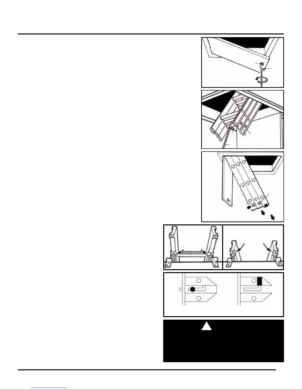
For correct identication, the front section of the ladder can be identied by its rounded feet.
1. Carefully push out the tacks (lightly tap with a hammer if necessary) and remove the plastic end caps from the bottom
of the REAR section of the ladder (See Figure A).
2. Slide the hinge guides (B1 & B2) onto the uppermost frame section. The brackets should be positioned outwards with
the double holed half uppermost (See Figure B).
3. Slide all the way up to the installed permanent top stops at other end of section.
4. Do not replace the plastic end caps (see later at Step 3 - Fitting Bottom Stops).
Rear
PARTS REQUIRED
B1. (1) HINGE GUIDE - LEFT
B2. (1) HINGE GUIDE - RIGHT
B2
Right side
Front
Figure A Figure B
3
Left side
B1
Page 5
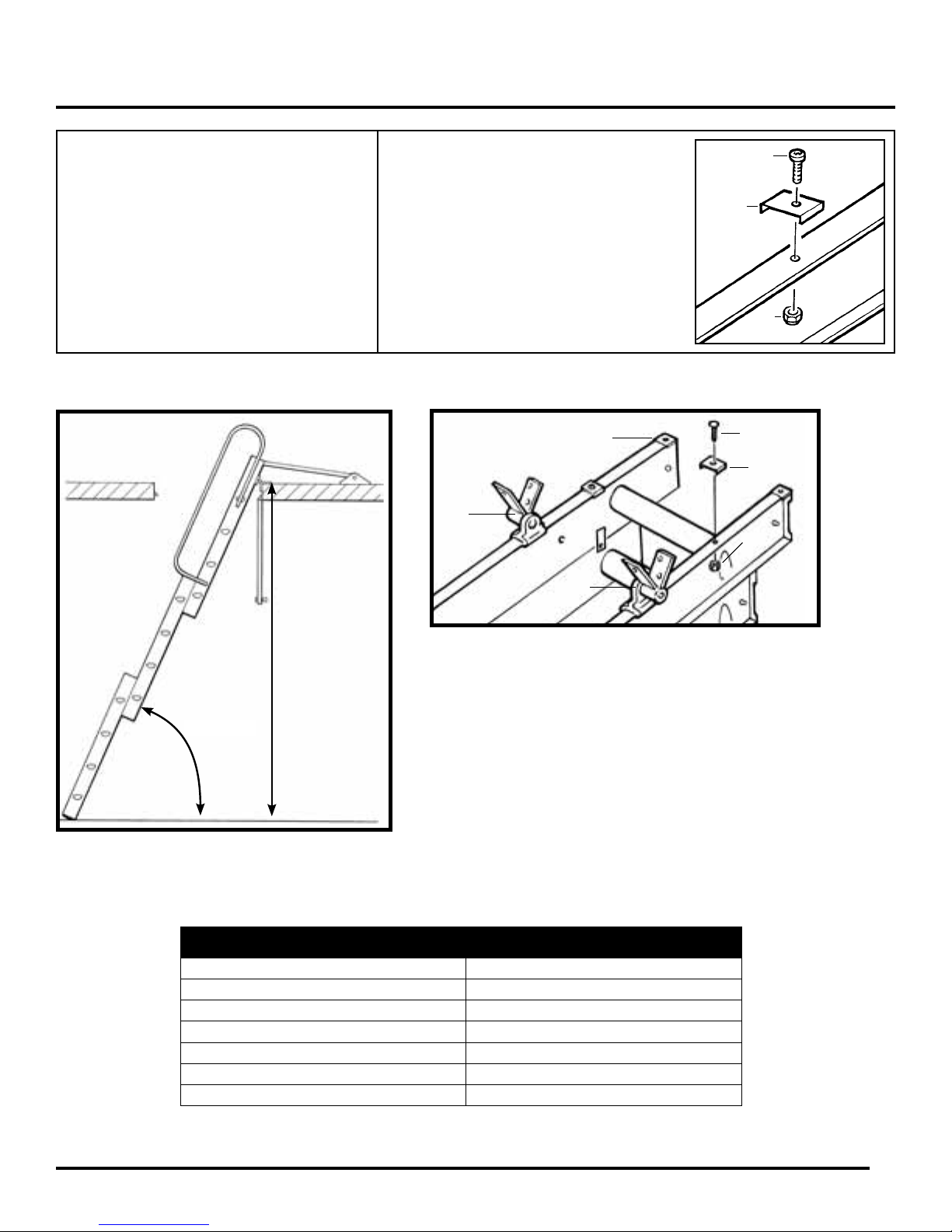
Step 2
Fitting Additional Top Stops
TOOLS REQUIRED
ADJUSTABLE WRENCH/PLIERS
Opened Requirements
PARTS REQUIRED
C1. (2) M4 X 8MM TOP STOP BOLTS
C2. (2) ADDITIONAL TOP STOPS
C3. (2) M4 LOCKING NUTS
Permanent top stop
B2
B1
C1
C2
C3
C1
C2
C3
68°- 80°
Floor to
oor height
Figure C
Depending on the oor to oor height (see Opened Requirements
left), you may need to add the additional top stops provided (C2)
(see table below).
1. If required, locate the additional top stops over the holes
approximately 6" below the permanent top stops on the rear
section of the ladder (See Figure C).
2. Ensure the hinge guides (B1 & B2) are already in place and
below the additional top stops when assembled.
3. Fix the additional top stops using two M4 bolts and nuts
supplied (C1 & C3).
Operating Heights
Feet & Inches Top Stops Required
7' 0" to 7' 6" YES
7' 6" to 7' 11" NO
7' 11" to 8' 5" YES
8' 5" to 8' 10-1/2" NO
8' 10-1/2" to 9' 4" YES
9' 4" to 9' 10" NO
4
Page 6
Step 3
Fitting Bottom Stops
TOOLS REQUIRED
LARGE FLAT SCREWDRIVER
PHILLIPS SCREWDRIVER
(small and medium)
HAMMER
1. Both end caps should now have been removed from the
rear section during previous Step 1. Remove end cap
from the rear section rail (on the same side as it is
intended to t the assist arm).
2. Slide the bottom stops (D1) onto the rear rails.
3. Position the bottom stops 6" from the end of
the rails (See Figure D).
4. Secure with screws (D2).
5. Replace the plastic end caps removed previously and
secure with tacks.
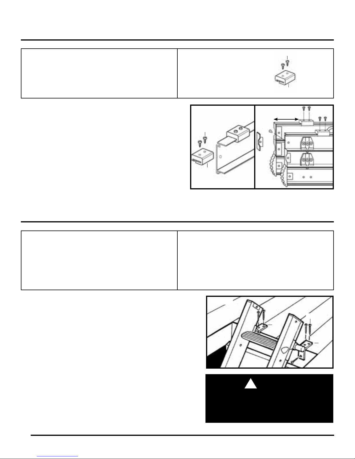
Step 4
Installing the Ladder
PARTS REQUIRED
D1. (2) BOTTOM STOPS
D2. (4) 12MM SCREWS
D2
D1
Figure D
D2
D1
6"
TOOLS REQUIRED
STEPLADDER
DRILL PLUS 1/16" BIT
LARGE FLAT SCREWDRIVER
PHILLIPS SCREWDRIVER (small and medium)
PENCIL
Minimum 3/4" ooring required to support Compact Attic Ladder (See
Appendix, Page 19, Figure 18). The ladder should be installed on the
same side of the opening as where the door hinges will be located.
1. With the ladder centered in the opening, locate the hinge guide
bracket arms (B1 & B2) on the top edge of the opening frame
(See Figure E).
2. Mark guide holes with a pencil and then predrill pilot holes
(1/16" diameter) for all screws.
3. Attach using 35mm screws (B3).
The bracket arms with two screw holes should be on top.
If ooring material covers the top edge of the opening be certain that
the ladder is completely stable. If necessary use longer screws to
penetrate the frame itself.
The ladder should now be free to swing from the hinges and slide
freely up and down the guides.
PARTS REQUIRED
B1. (1) HINGE GUIDE - LEFT
B2. (1) HINGE GUIDE - RIGHT
B3. (6) 35mm SCREWS
Figure E
B3
B1
B2
WARNING:
!
DO NOT stand on the ladder to do this. Either
using a second ladder, or from inside the attic
space, secure the hinges using six 35mm
screws supplied.
5
Page 7
Step 5
Installing the Assist Arm
TOOLS REQUIRED
AWL
LARGE FLAT SCREWDRIVER
PHILLIPS SCREWDRIVER
(small and medium)
ADJUSTABLE WRENCH/PLIERS
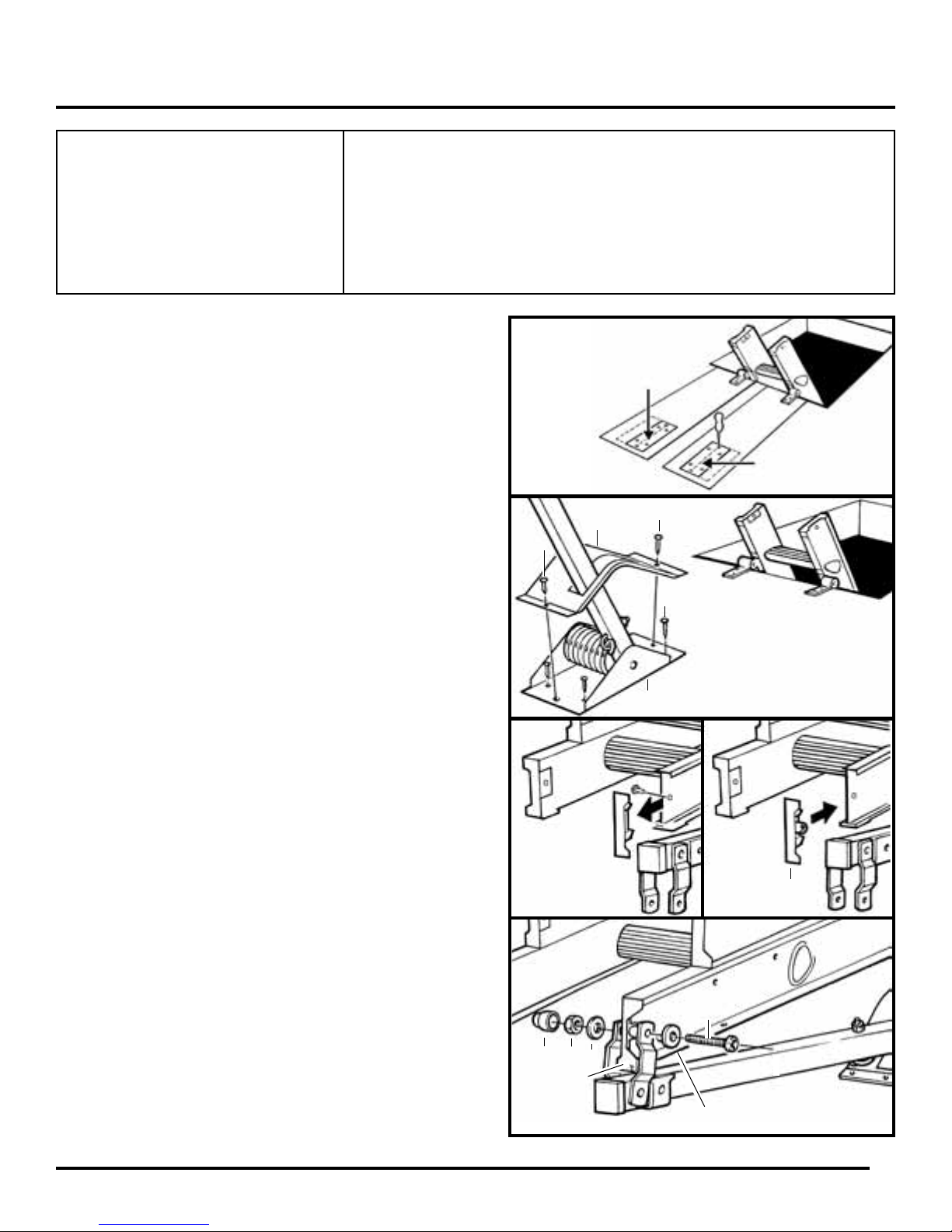
1. Position the template cut (from the back of the packaging
card) against either the left or right hand hinge guide
bracket (depending on which chosen side the power pivot
system is to be installed).
2. Using an awl or pencil mark the 6 applicable holes through
the template on to the attic oor (See Figure F).
3. Place the spring housing (F1) in position over the holes
ensuring the arm points AWAY from the rough opening
(with slot in cover on the left-hand side) (See Figure G).
4. Secure the spring housing to the attic oor with 20mm
screws (F3) through the 4 inner holes (See Figure G).
5. Place the housing cover (F2) over the spring housing and
attach using 20mm screws (F3) through the 2 remaining
outer holes (See Figure G)
PARTS REQUIRED
F1. (1) POWER PIVOT UNIT
F2. (1) HOUSING COVER
F3. (6) 20mm SCREWS
F4. (1) PIVOT TIP
F5. (1) M6 x 40mm BOLT
Figure F
F3
F6. (2) PLASTIC WASHERS
F7. (1) M6 LOCKING NUT
F8. (1) NUT CAP
F9. (1) BASE DRILL HOLE TEMPLATE
[ON BACK OF PACKAGING CARD]
For Right
Hand
Installation
For Left Hand
Installation
F2
F3
F3
6. Position the ladder in its fully stowed (closed) position
carefully in the opening.
7. Remove the tack and plastic top cap from the top of the
required side rail of the rear ladder section and discard
(See Figure H).
8. In their place attach Pivot Tip (F4) (See Figure H).
9. Locate the power arm linkage plates on either side of pivot
tip (F4)/ladder rail and align all holes.
10. Secure the rail to the linkage plates using bolt (F5),
washers (F6), nut and nut cap (F7 & F8) (See Figure I).
Ensure bolt (F5) and nut (F7) are tightened sufficiently to
allow the linkage to freely rotate without any looseness.
DO NOT over-tighten the nut as this will restrict smooth
operation of the ladder system.
Figure H
F8
F7
F4
F6
F1
Figure G
F4
F5
Figure I
F6
6
Page 8
Step 6
Handrail Assembly
TOOLS REQUIRED
ADJUSTABLE WRENCH/PLIERS
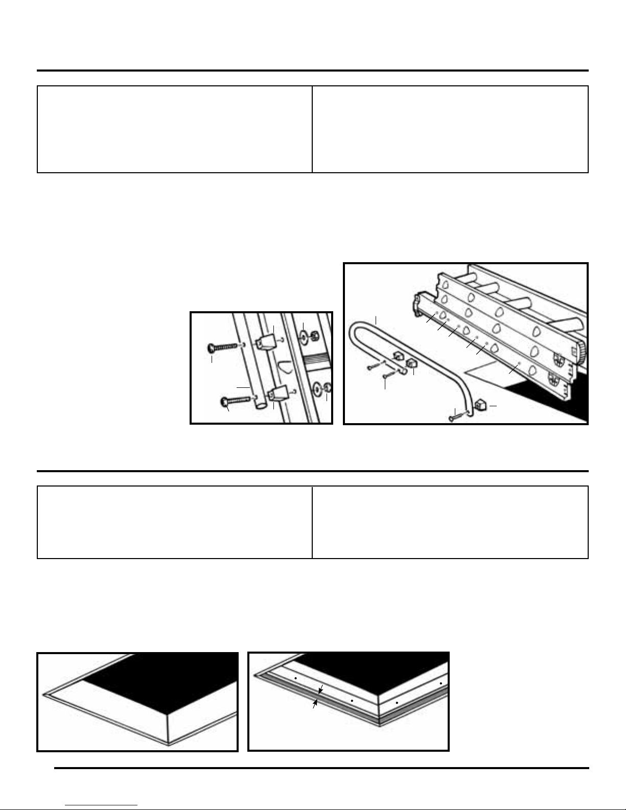
The handrail can be attached to either side of the ladder. It is advisable to attach the handle only after attaching the power
pivot arm.
1. Attach the handrail to your chosen side of the rear frame (See Figure J).
2. Use 3 spacers (E1), 60mm bolts (E2), washers and nuts (E3 & E4) supplied.
3. You have a choice of 2 different handrail heights which will be
dependent on the amount of “in-attic” handrail you require (See
Figure J).
Check that all components of the whole assembly are fully secure.
E3
*Position 1 attaches handrail
in top position.
**Position 2 attaches handrail
in low position.
Note: Position of the handrail
will affect the amount of space
needed in the attic.
E2
Handrail
E2
E1
E1
PARTS REQUIRED
E1. (3) HANDRAIL SPACERS
E2. (3) M5 x 60mm BOLTS
E3. (3) 25mm DIAMETER WASHERS
E4. (3) M5 LOCKING NUT
Handrail
1*
1*
2**
2**
E1
E2
E4
Figure J
E2
1*
2**
E1
Step 7
Finishing Opening for Door
TOOLS REQUIRED
SAW
SCREWS / NAILS
PHILLIPS SCREWDRIVER (small and medium)
Use a standard 1 x 3 solid wood plank for the door frame and a standard 1 x 2 solid wood board for the door jam.
1. Measure the width of the opening and cut the 1 x 3 wood board. Nail the trimmed 1 x 3 wood board to the header.
The bottom of the wood door frame should be ush with drywall on ceiling. Repeat for length of opening. (Figure K)
2. Measure inside width of frame and cut the 1 x 2 wood board. Nail the trimmed 1 x 2 wood board to the wood door
frame recessed the thickness of the door to create the door jam. Repeat for length of frame. (Figure L)
Jam should be recessed
Figure K
the thickness of door
PARTS REQUIRED
Standard 1 x 3 solid wood board (Door Frame)
Standard 1 x 2 solid wood board (Door Jam)
Your choice of nishing wood
Caution: Use of
materials greater than the
recommended thickness
may make the opening too
small to be usable.
Figure L
7
Page 9
Step 8
Hanging the Door
TOOLS REQUIRED
LARGE FLAT SCREWDRIVER
PHILLIPS SCREWDRIVER (small and medium)
The door thickness should be 3/4" cabinet grade
plywood cut 1/8" smaller than wood door frame
opening (from Step 7 - Finishing Opening for Door)
1. Screw hinges (G5) to one edge of the door using
3/4" wood screws.
2. Attach the hinges to the face of the frame on the
same end as you installed the ladder using 3/4"
wood screws (See Figure M).
PARTS REQUIRED
G5. (2) DOOR HINGES
(8) 3/4" WOOD SCREWS
Step 9
Locating the Hole for the Door Latch
TOOLS REQUIRED
PARTS REQUIRED
G5
Figure M
STEPLADDER
DRILL
1/2" DRILL BIT
SANDPAPER
LARGE FLAT SCREWDRIVER
PHILLIPS SCREWDRIVER (small and medium)
ADJUSTABLE WRENCH/PLIERS
TAPE MEASURE/RULER
PENCIL
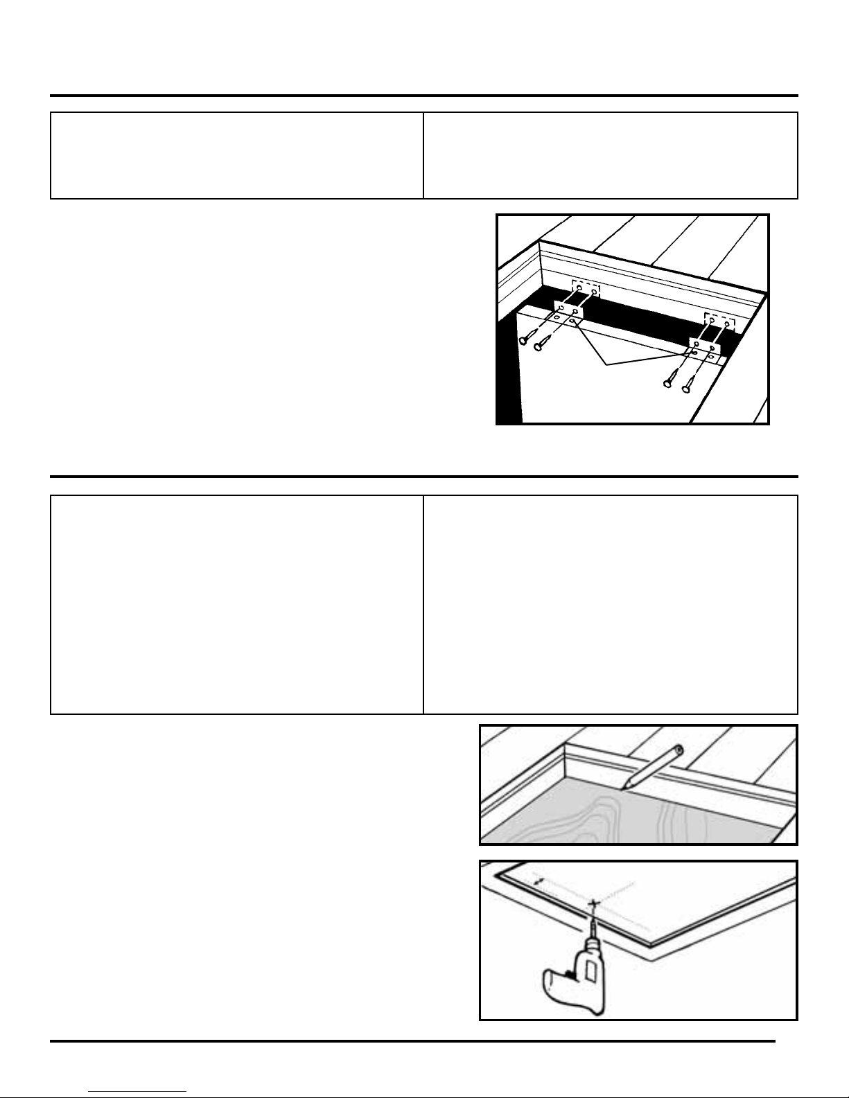
1. From inside attic, with door fully closed, mark the edge of the
jam on the door with a pencil. Measure back and transfer line to
opposite side of door.
2. Find the mid-point of the door edge opposite the hinged side.
This will give you your center line (See Figure N). Mark with a
pencil.
3. Measure exactly 1" in from the mark that was transferred, mark
with a pencil.
4. Drill a 1/2" hole in the center and sand off any rough edges.
A1. (1) LATCH
A2. (1) TRAVEL STOP RING
A3. (1) LATCH LEVER
A4. (1) M12 NUT
A7. (1) 12mm SCREW
1"
Door Center Line
1/2" hole
(STEP 9 CONTINUED ON NEXT PAGE)
Drill hole in the center
inside of door frame
Figure N
8
Page 10
(STEP 9 CONTINUED FROM PREVIOUS PAGE)
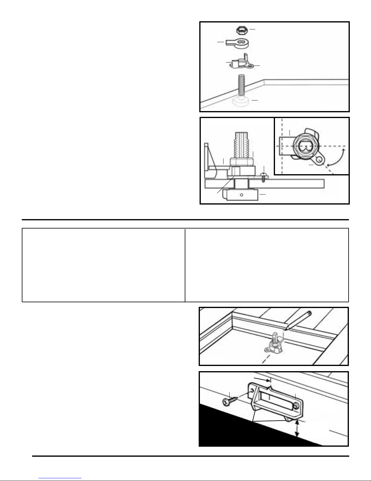
5. Pass the latch (A1) through the door hole from the
underside such that the position pointer points toward
the door edge (See Figure O).
A4
A3
6. Place the travel stop ring (A2) over the latch (A1) such
that the screw hole is at 45 degrees to the door center
line (See Figures O and P).
7. Place the latch catch (A3) over the latch (A1) and locate
into the latch groove such that the latch catch points
toward the door near edge and fully locates within the
travel stop ring (A2) (See Figures O and P).
8. Secure the travel stop ring (A2) using 12mm screw (A7).
9. Secure the catch assembly with M12 nut (A4) ensuring
the nut is tightened sufficiently to allow the catch to
rotate freely without any looseness (See Figure P).
Step 10
Attaching the Location Bracket
TOOLS REQUIRED
A2
A4
A3
A2
PARTS REQUIRED
Screw hole
A1
A7
A1
Door
Figure O
A3
45°
A2
Figure P
STEPLADDER
AWL
LARGE FLAT SCREWDRIVER
PHILLIPS SCREWDRIVER (small and medium)
TAPE MEASURE/RULER
PENCIL
When turned to the correct position, the catch lever will
engage in the location bracket to hold the door shut. Attach
as follows:
1. Mark a vertical line on the inside of the door jam
corresponding with the center line of the door catch
(See Figure Q).
2. Position the catch location bracket (A5) along the
bottom edge of the wood door jam (See Figure R).
3. Match up the indent mark on the bracket with the
vertical center line.
4. Make guide holes with the awl and attach using 2 of
the 3/4" wood screws supplied (A6).
5. Apply door labels, P/N103552-01 and P/N103553-01,
to the top side of the door, inside the attic.
A5. (1) LOCATION BRACKET
A6. (2) 3/4" WOOD SCREWS
(1) “WARNING” LABEL P/N103552-01
(1) “HOW TO USE” LABEL P/N103553-01
Figure Q
Center line
A6
Tabs ush with
bottom of door jam
Figure R
A5
Door Frame
Door jam
Thickness
of Door
9
Page 11
Step 11
Operating the Ladder
1. Locate the plastic stowing hook (G3) into one end of the assist pole (G2)
and push rmly to ensure the plastic stowing hook (G3) is fully located within the
pole. Secure hook (G3) with self-tapping screw. Push the plastic end plug into
the opposite end of the assist pole (G2).
2. To open the door, locate the hook (G3) into the slot in the latch (A1) and turn
the catch counterclockwise until it reaches the travel stop and then lower the
door (See Figure S).
3. Put the stowing hook (G3) over and at the center of the REAR ladder section
bottom rung and steadily pull the ladder outward and downward until both top
stops reach and make contact with the hinge guides (See Figure T).
4. Retract both right-hand side catches ‘C’ & ‘D’ (blue) and rotate both catch levers
upwards into the locked open position (See Figures T and W).
Figure S
A1
G3
5. To extend the ladder, retract left-hand catch ‘A’ (black) while supporting the front
frame of the ladder. Lower the frame slowly until catch ‘A’ (black) engages again
(Figure U).
6. Then retract catch ‘B’ (black) and lower the middle frame until catch ‘B’ (black) is
engaged in your required position. Extend the ladder until the feet rest rmly on
the oor (Figure U).
7. When the ladder has been fully opened, rotate both right-hand side catch levers
downward to unlock and release both catches ‘C’ and ‘D’ (blue) and ensure both
catches are fully engaged. DO NOT use ladder with any catches (‘A’, ‘B’, ‘C’ or
‘D’) disengaged. Read the safety labels on the product.
8. Ensure the ladder is pulled down so that the top stops (or additional top stops if
installed) rest rmly on the hinge guides. This supports the top section and
prevents it from sliding down when climbed.
9. Check the ladder angle against the safety label or refer back
to opened requirements on page 2.
Stowing the Ladder
10. Retract both right-hand side catches ‘C’ & ‘D’ (blue) and rotate
both catch levers upwards into the locked open position
(Figure W).
11. To stow the ladder, retract catch ‘A’ (black), slide the front
frame fully upwards until catch engages again.
Additional
Top stops
Assembled
Figure V
Figure T
Figure U
Catches
‘C’ & ‘D’
G3
G2
C
B
No Additional
Top stops
Assembled
D
A
12. Repeat step 11 for catch ‘B’ (black) and the middle ladder frame
13. Reverse step 10 and ensure both right-hand side catches ‘C’
and ‘D’ (blue) are fully engaged.
14. Engage the plastic stowing hook (E3) over and at the center
of the REAR ladder section bottom rung. While maintaining
the assist pole in the vertical position, push the ladder
vertically upwards.
15. Continue to slowly push the ladder up and fully into the attic hole.
16. Use the assist pole to raise the door and turn the latch
clockwise to close.
Released/
Figure W
DO NOT attempt to climb your attic ladder until you
have checked that it is pulled down to the stops.
Fully read all safety labels and ensure that it is set
at the correct angle. Ensure that the locking catches
are fully engaged.
engaged
WARNING:
!
Retracted/
locked open
10
Page 12
Appendix
Creating a Rough Opening
Section 1.1
Important Questions
Is your ceiling and joist structure suitable for this installation?
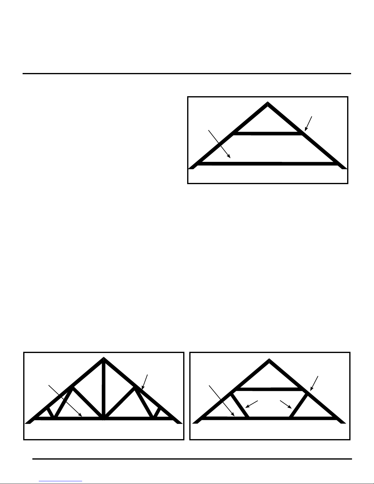
This attic ladder can be installed in structures with
conventional wood roof frames (See Figure 1). If a
ceiling is present, you must have an attic hole in
the ceiling that allows you to enter the overhead
space for a pre-installation inspection.
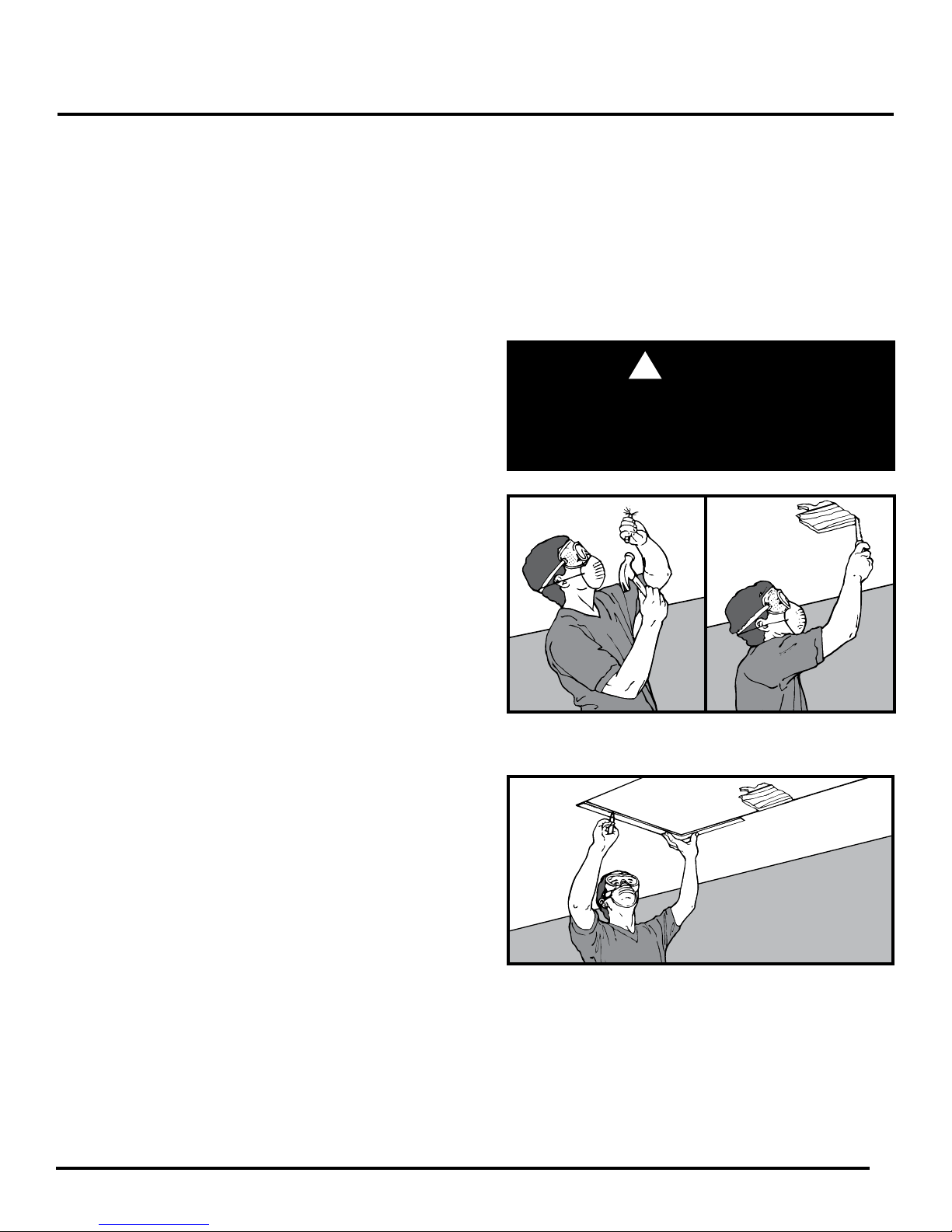
Roof support structures that have braces connected
to the ceiling joists or which use trusses (See Figure 2)
cannot be cut without destroying the load-bearing
capacity of that section of the roof. Do not cut joists
that are part of a braced conventional frame or
truss without rst consulting an architect or
structural engineer (see the Yellow Pages under
“Architects or Structural Engineers”).
Ceiling Joist
Conventional Roof Frame
Rafter
Figure 1
The attic ladder should not be installed in a ceiling that has any of the following:
– Components of heating/cooling systems embedded in the ceiling
– Joists made of materials other than wood
– Metal reinforced plaster
– Suspended ceilings
If your ceiling contains any of the above, do not attempt to install the attic ladder. Contact a professional for assistance with your specic needs (see the Yellow Pages under “Heating and Cooling Contractors, Building Contractors,
Carpenters, Home Builders, Home Improvements, or Contractors-General”).
Do these instructions meet your needs?
These instructions describe how to install the attic ladder parallel or perpendicular to the ceiling joists. Contact a
professional if you want the attic ladder installed in some other direction relative to the joists.
Is your ceiling and joist structure suitable for this installation?
WARNING: DO NOT CUT THESE TYPES OF STRUCTURES WITHOUT
CONSULTING AN ARCHITECT OR STRUCTURAL ENGINEER.
Ceiling Joist
Rafter
Ceiling Joist
Rafter
Truss Roof Frame
Figure 2
11
Braces
Conventional Roof Frame with Braces
Connected to Ceiling Joists
Page 13

Section 1.2
Tools and Materials Needed
Materials:
– Several pieces of joist-sized lumber (the amount depends on the specic installation)
– 16d sinker nails or screws of equivalent strength (24-60 depending on the specic installation)
– 20d sinker nails or screws of equivalent strength are needed for installations where joists are cut
Stepladder:
– You will need a stepladder that is tall enough so that you can get into the overhead space without
stepping above the working height of the stepladder. The working height of the stepladder is two
steps down from the top.
– Your stepladder must also have a duty rating that is greater than the sum of your weight plus
the weight of the attic ladder and any additional materials used for installation.
CAUTION: Be careful when using a stepladder to climb into and out of the overhead space.
Tools For Creating a Rough Opening:
– Flashlight or extension light
– Claw hammer
– Pencil
– Handsaw/power saw
– Tape measure
– Framing square
– Tools to cut a hole in the existing ceiling
Safety Equipment:
– Gloves
– Safety goggles
– Dust mask
12
Page 14

Section 1.3
Finding a Suitable Location
Before Proceeding: You must have a suitable ceiling and joist structure, tools and materials needed, and a level and
at location in the ceiling.
Goal: To nd a location free of hazards and obstructions that will provide room for the installation and use of the attic ladder.
STEP 1. Pick a potential location for installation. Check for the size of rough opening shown on the box or in in the
pre-installation checklist.
If you are installing the attic ladder in a garage, don’t forget to consider where cars will be parked.
STEP 2. If there is no ceiling and the attic ladder will
t between the joists so that no joists need
to be cut, go to Section 1.5 “FRAMING
THE ROUGH OPENING”.
If there is no ceiling, but one or more
joists need to be cut, go to Section 1.4
“CUTTING THE CEILING JOISTS”.
If there is a ceiling at this location, you
will need to inspect the attic area
above this location as described in
steps 3 and 4.
STEP 3. Go into the overhead space and nd the area above your chosen location.
This area may be located by:
A) Listening for tapping from below
B) Measuring distances from walls or other objects common to the overhead space and the room below
FOR YOUR SAFETY, WATCH OUT FOR OVERHEAD HAZARDS.
DO NOT
stand or sit on the ceiling or insulation covering the ceiling — the ceiling is not made to support your
weight. You can fall through the ceiling even though it
looks solid! Only the joists can support weight.
Watch out for sharp nails sticking through the roof.
WARNING:
!
WARNING: Do not drive metal nails or other conductive objects into the ceiling unless you are sure they will not
contact electric wires. Contact with an electrical wire can be deadly.
STEP 4. At this location in the overhead space:
A) Check that there is enough space for you to safely move around
during installation.
B) Check the overhead space for storage space adjacent to the chosen location. If walking
or crawling in the overhead space is desired, make sure that there is enough room to do so.
C) Check above your chosen location for hazards and obstructions such as:
– Electrical wires
– Pipes
– Heating and cooling ducts
– Furnaces
– Hot water heaters or other obstructions
Note: To check for hazards, you will need to move insulation away from your chosen location.
Wear a dust mask, safety goggles, and gloves and keep your body covered to prevent ne cuts
from berglass. Gently push aside insulation to avoid stirring up dust that may be harmful to your
eyes and lungs.
STEP 5. If any hazards or obstructions are present at your chosen location, look for another location or have
the hazards or obstructions moved by professionals (see the Yellow Pages under “Electrical
Contractors, Heating and Cooling Contractors, and Plumbing Contractors”).
13
Page 15
Section 1.4
Cutting a Hole in the Ceiling
Before Proceeding: You must have a location that:
A) Is free of hazards and obstructions in the overhead space.
B) Is free of hazards in the ceiling.
C) Provides enough room for installation.
D) Provides enough room to use the attic ladder.
Goal: To cut a hole, that is the correct size, in the ceiling at the desired location.
STEP 1. Prepare the room by moving furniture,
covering ooring with a drop cloth and
removing children and pets to a safe
distance.
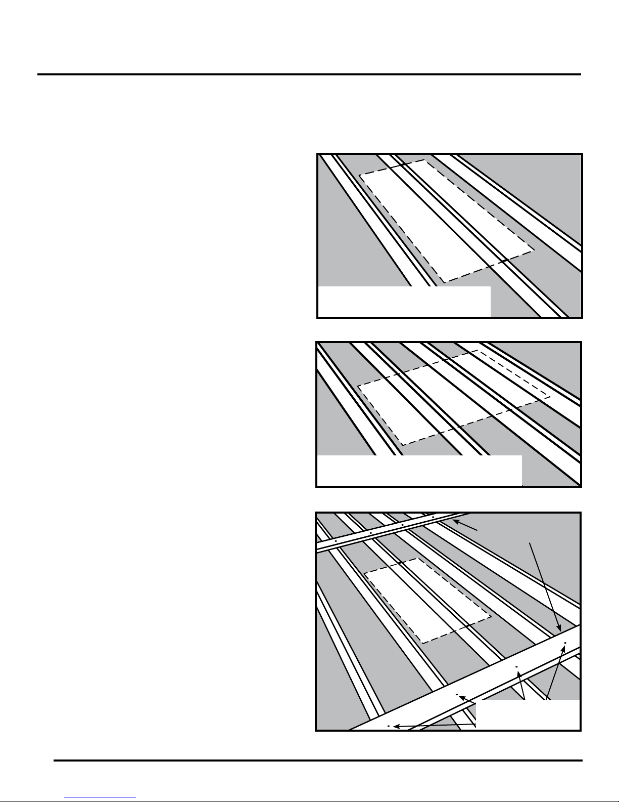
STEP 2. Put on safety goggles and a dust mask.
These will keep pieces of ceiling particles
and dust from falling into your eyes, mouth
or nose as you make a starter hole and cut
into the ceiling.
STEP 3. With a hammer and chisel, make a starter
hole near the center of the chosen location
(See Figure 4).
STEP 4. Enlarge the opening with a saw until you
can see a joist (See Figure 5).
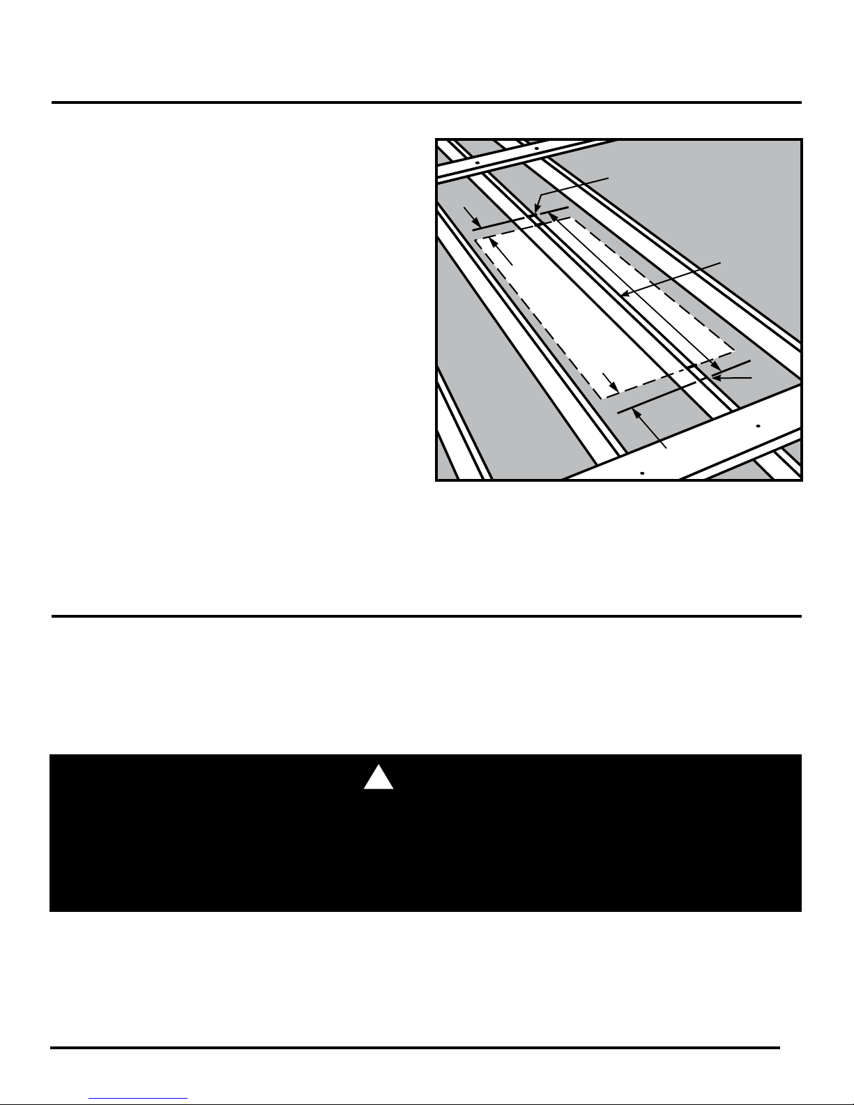
STEP 5. Draw a rectangle the size of the rough
opening on the ceiling, with one edge
parallel to a joist (See Figure 6). You may do
this by sawing until you reach a joist and use
it as a frame of reference. (The size of the
rough opening must be at least 18" x 24".)
Note: Locating at least one edge of the
opening along a ceiling joist will allow the
joist to be used as a side of the frame you
will build. This will simplify framing the
rough opening.
STEP 6. Cut out the rest of the ceiling within the
marked outline following these instructions:
A) Do not cut any joists at this
time. Cut through the ceiling only.
B) Remove the ceiling in small pieces
because ceiling material can be
very heavy.
STEP 7. If no joists span the hole in the ceiling, go
to Section 1.5 “FRAMING THE ROUGH
OPENING”.
If any joists span the hole, go to Section 1.4
“CUTTING THE CEILING JOISTS”.
DO NOT stand saw, cut, or hammer into the ceiling
until you are sure that the location is free of hazards
and obstructions in the ceiling and attic. Contact with
an electrical wire can be deadly.
Figure 4 Figure 5
Figure 6
WARNING:
!
14
Page 16
Section 1.4
Cutting a Hole in the Ceiling
Before Proceeding: You must have either exposed joists or a correctly sized hole at the desired ceiling location.
Goal: To cut out any joists that are in the way of your chosen location. Before cutting the joists, you must attach
them to other joists in the overhead attic to keep the ceiling from sagging or completely collapsing.
STEP 1. If the room has a ceiling and you have cut
the required hole, go to Step 2.
If the room has no ceiling, you will need to
mark the joists according to (A) or (B) below.
(A) If the chosen location is parallel to the
joists, mark the rough opening length on
top of the joists (See Figure 7).
Do not cut the joist at this mark.
(B) If the chosen location is perpendicular to
the joists, mark the rough opening width on
top of the joists (See Figure 8).
Do not cut the joist at this mark.
STEP 2. Cut 2 joist-sized boards long enough to
span 2 joists on each side of your chosen
location (See Figure 9). These boards will
support the joists that will be cut and help
keep the ceiling from sagging or completely
collapsing while you are working in the
overhead space.
STEP 3. Place these boards approximately 24"
from the edge of your chosen location and
nail (See Figure 9).
Note: The 24" distance is needed to
give you room to hammer nails into the
frame that you will build in the next section.
Dotted Line Indicates Your Chosen
Location (Location Parallel to Joist).
Figure 7
Dotted Line Indicates Your Chosen
Location (Location Perpendicular to Joist).
Figure 8
15
Joist Support
Boards
Nail or Screw
Boards to Each Joist
Figure 9
Page 17
Section 1.4 (Continued)
Cutting the Ceiling Joists
STEP 4. Next, determine where the joist(s) should
be cut. Figure 10 shows where to mark the
joist(s) that span your chosen location. Note
that the joist(s) should be marked back
from the edge of your location a distance of
2 times the joist thickness (usually three
inches). This leaves room for two joist-sized
headers to be placed against each end of
the cut joist(s) (See Figure 16 on page 18).
Note: In some homes, especially older
ones, the joists may be slightly thicker than
the lumber you can currently buy. If your
joists have a different thickness than the
lumber you will be using for the headers,
you will need to mark the joists back from
the edge of your location a distance of two
times the header thickness instead of the
joist thickness.
STEP 5. Saw through the joist(s) being careful not to
cut through the ceiling and making sure the
cut ends of the joist(s) are at and vertical.
2 x Joist
Thickness
Dotted
Line Indicates
Your Chosen
Location
Cut
Here
Section of Joist
to be Removed
Cut
Here
2 x Joist
Thickness
Figure 10
Section 1.5
Framing the Rough Opening
Before Proceeding: You should have a space between the joists at least 18". Any cut joists must be attached to uncut
joists.
Goal: To create a four-sided frame the size of the rough opening using joist-sized lumber. This frame will be made of
single or double thickness headers and stringers depending upon the particular installation. The frame is necessary to
support the attic ladder and to reinforce the roof and ceiling structure.
WARNING:
!
FOR YOUR SAFETY, WATCH OUT FOR OVERHEAD HAZARDS.
DO NOT Do not stand or sit on the ceiling or insulation covering the ceiling — the ceiling is not made to support your
weight. You can fall through the ceiling even though it looks solid! Only the joists can support weight. To avoid falling
through the ceiling, you may want to make a working platform by laying boards across the joist. Watch out for sharp
nails sticking through the roof.
16
Page 18
Section 1.5 (Continued)
Framing the Rough Opening
Installing Headers
If no joists have been cut, go to “Single Headers” below.
If any joists have been cut, go to “Double Headers” on page 18.
Single Headers
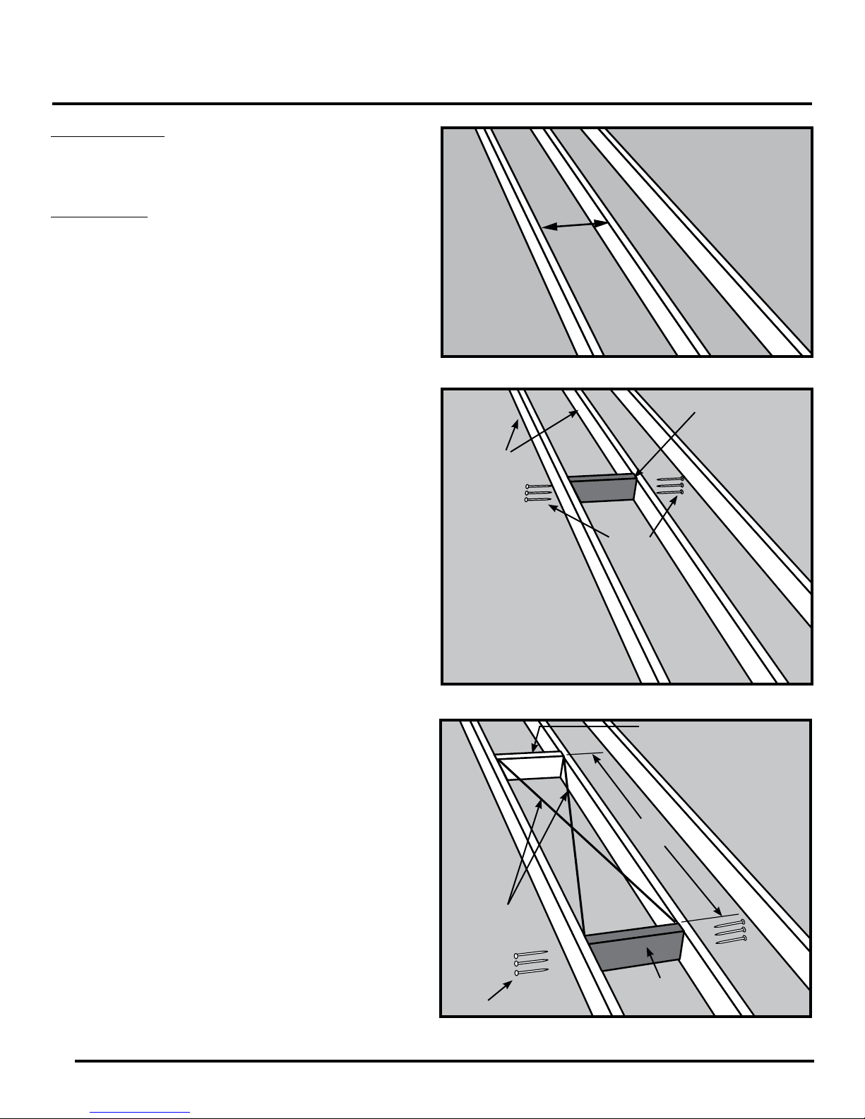
STEP 1. Measure the header length “H” between
the joists (See Figure 11).
STEP 2. Cut 2 headers this length. Use
joist-sized lumber.
STEP 3. Place one of these headers at one end of
your chosen location (See Figure 12). The
header must t snugly between the joists.
Hammer it into position if necessary; if it is
more than 1/16" too long, trim it. If it is
more than 1/16" too short, cut another piece.
STEP 4. Square the header to one joist and drive
3 nails (16d) through the joist and into the
header. Check for squareness and drive
3 nails (16d) through the other joist and
into the header (See Figure 12). It is very
important that header board is vertically
square as well as horizontally square to
side joists.
STEP 5. Position the second header at least 24" from
the rst one and repeat Step 4 (See Figure 13).
STEP 6. The frame for the rough opening requires
four sides. The headers make up two of
those sides. If your ceiling joists are spaced
so that they make up the other two sides of
the rough opening, check the opening for
squareness by measuring across the
diagonals. The measurements should be
within 1/8” to be considered square
(See Figure 13).
If your ceiling joists do not make up the
other two sides of the rough opening, you
need to install one or two additional pieces
of lumber to frame the other side(s) of the
rough opening, go to “Installing Stringers”
on page 19.
H
Figure 11
Header
Joists
Nails
Drive 3 Nails (16d) into
each end of the Header
Figure 12
Header
At
least
24"
17
Diagonal
Measurements
Nails
Header
Figure 13 How to check for square
Page 19

Section 1.5 (Continued)
Framing the Rough Opening
Double Headers
STEP 1. Measure the header length “H” between
the uncut joists (See Figure14).
STEP 2. Cut 4 headers this length. Use joist-sized
lumber.
STEP 3. Place one of these headers against the end
of the cut joist(s) (See Figure 15). It must
t snugly between the uncut joists.
Hammer it into position if necessary; if it is
more than 1/16" too long, trim it. If it
is more than 1/16" too short, cut
another piece.
STEP 4. Square the header to the uncut joist and
nail the header to the end of the cut
joist(s) with 3 nails (See Figure 15).
STEP 5. Check header for squareness then drive
3 nails through each joist into each
end of the header (See Figure 15).
STEP 6. Place a second header against the rst
header and nail it to the rst header with
3 nails between each joist (See Figure 16).
STEP 7. Drive 3 nails through the joists into each
end of the second header (See Figure 16).
STEP 8. Repeat steps 3-7 to install headers at the
opposite end of the opening.
STEP 9. To frame the other side(s) of the rough
opening, go to “Installing Stringers” on page 19.
H
Figure 14
Cut Joist
First Header
Nails
Uncut Joists
Figure 15
Nails
Figure 16
Second Header
18
Page 20

Section 1.5 (Continued)
Framing the Rough Opening
Installing Stringers
STEP 1. Measure the stringer length “S” between
the headers (See Figure 17).
STEP 2. Cut a stringer to this length. Use
joist-sized lumber.
STEP 3. If the ceiling joist does not provide one side
of the frame, then cut a second stringer the
same length as the rst one. Note that only
one stringer is needed in Figure 17 because
the ceiling joist provides one side of
the frame.
STEP 4. Position the stringer(s) along the unframed
side(s) of your location (See Figure 18).
Check that the inside dimensions of the
frame are at least 18" x 24".
STEP 5. To attach the stringer(s) to the headers, use
nails that are long enough to go through
both headers and into the stringer at least
one inch. In most cases, a 4" nail (20d)
will be long enough. Square the stringer(s)
to the headers at one end and drive 3 nails
through the headers and into the stringer.
Check for squareness, then nail the other
end. Check the rough opening for
squareness by measuring across the
diagonals. The two measurements must
be within 1/8" to be considered square
(See Figure 18).
Headers
S
Headers
Figure 17
Stringer
Note: A 3/4" wood oor 27" min. deep by the full width of
your opening is required for the attachment of the assist
arm. Please refer to Step 5 on page 6 of this manual for
instructions on attaching assist arm.
19
Diagonal
Measurements
Support oor for power
assist arm min. 27" by
full width of opening
Figure 18
Nails
27"
Full Width
of opening
Page 21

Compact Attic Ladder
ALUMINUM
BUILT FOR SMALL ATTIC OPENINGS
Escalera de Compacta Para Ático
ALUMINIO
CONSTRUIDA PARA ABERTURAS DE ÁTICO PEQUEÑAS
-
Índice
Página
Antes de comenzar 2
Preguntas importantes 3
Paso 1 Ensamblaje de la escalera 3
Paso 2
Paso 3 Instalación de topes inferiores 5
Paso 4 Instalación de la escalera 5
Paso 5 Instalación del brazo de ayuda 6
Paso 6 Pasamanos 7
Paso 7
Paso 8 Colgado de la puerta 8
Paso 9
Paso 10
Paso 11 Manejo de la escalera 10
Apéndice Creación de una abertura preliminar 11
Instalación de topes
superiores adicionales
Acabado de la abertura
para la puerta
Ubicación del oricio para la
cerradura de la puerta
Sujeción del soporte para el
pestillo de la cerradura
Sección 1.1 Preguntas importantes 11
4
7
8-9
9
Sección 1.2 Herramientas y materiales necesarios 12
Sección 1.3 Búsqueda de una ubicación adecuada 13
Sección 1.4 Corte de una abertura en el cielo raso 14-16
Sección 1.5 Enmarcado de la abertura preliminar 16-19
Page 22

Antes de comenzar
HERRAMIENTAS
REQUERIDAS
ESCALERA TIPO TIJERA
PUNZÓN
SIERRA
TALADRO MÁS BROCA DE 1/2" y 1/16"
DESTORNILLADOR DE PALA
GRANDE
DESTORNILLADOR PHILLIPS
(pequeño y mediano)
LLAVE AJUSTABLE / ALICATES
CINTA MÉTRICA / REGLA
MARTILLO
LÁPIZ
A Abertura mínima acabada (longitud) 0.53m
B Abertura mínima acabada (ancho) 0.38m
MATERIAL DE PUERTA REQUERIDO
ASEGÚRESE DE UTILIZAR MADERA LAMINADA DE 3/4" PARA ARMARIOS.
TABLA DE MADERA MACIZA DE 1 X 3 REQUERIDA PARA EL MARCO
DE LA PUERTA
TABLA DE MADERA MACIZA DE 1 X 2 REQUERIDA PARA LA
CUÑA DE LA PUERTA
AL COMIENZO DE CADA PASO A LO LARGO DE ESTE
MANUAL DE INSTRUCCIONES, SE ENUMERARÁN LOS
TORNILLOS/CLAVOS Y COMPONENTES NECESARIOS.
SI CUALQUIER PIEZA ESTÁ FALTANDO O ESTÁ ROTA,
POR FAVOR LLAME AL SERVICIO AL CLIENTE AL
1-888-523-3370.
Escalera de ático compacta
C
D* Altura mínima para guardado requerida en el ático 0.72m
E**
Hacia atrás de la apertura preliminar
Altura máxima 3.00m
Altura mínima 2.13m
Longitud mínima requerida
1.12m
Requisitos en la posición cerrada Requisitos en la posición abierta
D*
B
E**A
68°- 80°
C
*En la posición inferior del pasamanos - 0.72m
En la posición superior del pasamanos - 0.97m
2
**En la posición inferior del pasamanos - 1.12m
En la posición superior del pasamanos - 1.37m
Page 23

Preguntas importantes
Lea completamente las instrucciones antes de empezar. Esto es necesario para garantizar que usted tiene una ubicación adecuada
para la escalera de ático y la capacidad para instalarla de manera segura y apropiada.
¿Es usted capaz de instalar esta escalera de ático?
Para instalar esta escalera de ático usted debe tener habilidades para aserrar, escuadrar y alinear, similares a las habilidades
requeridas para instalar un marco de ventana o puerta. Si usted no tiene estas habilidades, usted debería contratar un carpintero
profesional para instalar esta unidad (consulte las Páginas Amarillas bajo los títulos de “Contratistas de Construcción, Carpinteros,
Constructores de Casas, Remodelaciones de Casas, o Contratistas en General”)
¿Satisface esta escalera de ático sus necesidades?
Esta escalera de ático sólo es para uso residencial. La instalación de esta escalera de ático en edicaciones comerciales y
apartamentos podría violar los códigos de construcción que exigen cielos rasos con capacidad de resistencia al fuego y prohíben
almacenar materiales en el espacio superior. Verique con su jefe de bomberos local o con el ministerio de construcciones antes de
instalar la escalera de ático.
La capacidad de la escalera de ático (persona más materiales que se cargan) es de 250 libras.
Esta escalera de ático está hecha para el rango de alturas de cielos rasos mostrado en el embalaje/paquete. No instale la escalera
de ático en un cielo raso que tiene una altura fuera de este rango. Alterar la escalera de ático para acomodarse a otras alturas es
inseguro y nunca debe intentarse.
ESTA ESCALERA DE ÁTICO VIENE CON BISAGRAS Y CERRADURA PARA INSTALAR
UNA PUERTA (NO INCLUIDA). PARA MODIFICAR O CREAR UNA ABERTURA NUEVA, POR
FAVOR CONSULTE EL APÉNDICE (PÁGINA 11).
Paso 1
Ensamblaje de la escalera
HERRAMIENTAS REQUERIDAS
MARTILLO
Para la identicación correcta, la sección delantera de la escalera puede identicarse por sus patas redondeadas.
1. Extraiga cuidadosamente las tachuelas (golpee suavemente con un martillo en caso de ser necesario) y retire las tapas de extremo
plásticas de la parte inferior de la sección TRASERA de la escalera (vea la Figura A).
2. Deslice las guías de bisagra (B1 & B2) sobre la sección más alta del marco. Los soportes deben colocarse hacia afuera con la
mitad de doble oricio más alta (vea la Figura B).
3. Deslice todo el recorrido hasta los topes superiores de instalación permanente en el otro extremo de la sección.
4. No vuelva a colocar las tapas de extremo plásticas (vea más adelante en el Paso 3 - Instalación de los peldaños inferiores).
Parte
trasera
PIEZAS REQUERIDAS
B1. (1) GUÍA DE BISAGRA - IZQUIERDA
B2. (1) GUÍA DE BISAGRA - DERECHA
B2
Lado
derecho
Lado
izquierdo
Parte
delantera
Figura A Figura B
B1
3
Page 24

Paso 2
Instalación de los topes superiores adicionales
HERRAMIENTAS
REQUERIDAS
LLAVE AJUSTABLE / ALICATES
Requisitos en la posición abierta
PIEZAS REQUERIDAS
C1. (2) PERNOS DE TOPES
SUPERIORES M4 X 8MM
C2. (2) TOPES SUPERIORES
ADICIONALES
C3. (2) TUERCAS DE FIJACIÓN M4
Tope superior
permanente
B2
B1
C1
C2
C3
C1
C2
C3
68°- 80°
Altura de
piso a piso
Figura C
Dependiendo de la altura de piso a piso (vea a la izquierda los
Requisitos en la posición abierta), usted podría necesitar agregar los
topes superiores adicionales suministrados (C2) (vea abajo la tabla).
1. En caso de requerirse, coloque los topes superiores adicionales
en los oricios a aproximadamente 6” debajo de los topes
superiores permanentes en la sección trasera de la escalera
(vea la Figura C).
2. Verique que las guías de bisagra (B1 y B2) ya estén en su
sitio y debajo de los topes superiores adicionales cuando están
instalados.
3. Fije los topes superiores adicionales utilizando las dos tuercas y
pernos M4 suministrados (C1 y C3).
Alturas de funcionamiento
Pies y pulgadas Topes superiores requeridos
2.13m hasta 2.28m SÍ
2.28m hasta 2.41m NO
2.41m hasta 2.57m SÍ
2.57m hasta 2.71m NO
2.71m hasta 2.84m SÍ
2.84m hasta 3.00m NO
4
Page 25

Paso 3
Instalación de topes inferiores
HERRAMIENTAS REQUERIDAS
DESTORNILLADOR DE PALA GRANDE
DESTORNILLADOR PHILLIPS
(pequeño y mediano)
MARTILLO
1. En este momento, ambas tapas de extremo debieron
haber sido retiradas de la sección trasera durante el
anterior Paso 1. Retire la tapa de extremo del riel de la
sección trasera (en el mismo lado tal como está pensado
para instalar el brazo de ayuda).
2. Deslice los topes inferiores (D1) sobre los rieles traseros.
3. Coloque los topes inferiores a 0.15m del extremo de los
rieles (vea la Figura D).
4. Fije con los tornillos (D2).
5. Coloque nuevamente las tapas de extremo plásticas reti
radas previamente y asegure con tachuelas.
Paso 4
Instalación de la escalera
PIEZAS REQUERIDAS
D1. (2) TOPES INFERIORES
D2. (4) TORNILLOS 12 MM
D2
D1
Figura D
D2
D1
6"
HERRAMIENTAS REQUERIDAS
ESCALERA TIPO TIJERA
TALADRO MÁS BROCA DE 1/16"
DESTORNILLADOR DE PALA GRANDE
DESTORNILLADOR PHILLIPS (pequeño y mediano)
LÁPIZ
Espesor mínimo de piso de 3/4" requerido para soportar la Escalera de
Ático Compacta (vea el Apéndice, Página 19, Figura 18). La escalera debe
instalarse en el mismo lado de la abertura donde se colocarán las bisagras
de la puerta.
1. Con la escalera centrada en la abertura, coloque los brazos de soporte
de las guías de bisagra (B1 y B2) en el borde superior del marco de la
abertura (vea la Figura E).
2. Marque con un lápiz los oricios de guía y luego pretaladre los oricios
piloto (1/16” de diámetro) para todos los tornillos.
3. Sujete utilizando tornillos de 35mm (B3).
Los brazos de soporte con dos oricios para tornillo deben estar en la parte
superior.
Si el material del piso cubre el borde superior de la abertura, verique que la
escalera está completamente estable. Si es necesario, utilice tornillos más
largos para penetrar el marco en sí.
En este momento, la escalera debe estar libre para girar en las bisagras y
deslizarse libremente hacia arriba y abajo por las guías.
PIEZAS REQUERIDAS
B1. (1) GUÍA DE BISAGRA - IZQUIERDA
B2. (1) GUÍA DE BISAGRA - DERECHA
B3. (6) TORNILLOS de 35 MM
Figura E
B1
ADVERTENCIA:
!
NO se pare sobre la escalera para hacer
esto. Utilizando una segunda escalera, o
desde el interior del ático, asegure las
bisagras utilizando seis tornillos de 35mm
suministrados.
B3
B2
5
Page 26

Paso 5
Instalación del brazo de ayuda
HERRAMIENTAS REQUERIDAS
PUNZÓN
DESTORNILLADOR DE PALA GRANDE
DESTORNILLADOR PHILLIPS
(pequeño y mediano)
LLAVE AJUSTABLE / ALICATES
1. Coloque la plantilla cortada (procedente de la parte trasera
de la caja de cartón de embalaje) contra el soporte de la
guía de bisagra izquierda o derecha (dependiendo del lado
elegido donde se instalará el sistema de pivote de fuerza).
2. Utilizando un punzón o lápiz, marque los 6 oricios
respectivos a través de la plantilla sobre el piso del ático
(vea la Figura F).
3. Coloque el alojamiento (F1) del resorte sobre los oricios
asegurándose que el brazo quede dirigido en dirección
contraria de la abertura preliminar (con la ranura de la
cubierta en el lado izquierdo) (vea la Figura G).
4. Fije el alojamiento del resorte al piso del ático mediante los
tornillos de 20 mm (F3) a través de los 4 oricios interiores
(vea la Figura G).
5. Coloque la cubierta (F2) del alojamiento sobre el
alojamiento del resorte y sujete utilizando los tornillos de
20 mm (F3) a través de los 2 oricios exteriores restantes
(vea la Figura G)
6. Coloque cuidadosamente la escalera en su posición
totalmente guardada (cerrada) en la abertura.
PIEZAS REQUERIDAS
F1. (1) UNIDAD DE PIVOTE DE
FUERZA
F2. (1) CUBIERTA DEL ALOJAMIENTO
F3. (6) TORNILLOS de 20 MM
F4. (1) PUNTA DE PIVOTE
F5. (1) PERNO M6 x 40 MM
Para instalación
derecha
Figura F
F2
F3
F6. (2) ARANDELAS PLÁSTICAS
F7. (1) TUERCA DE FIJACIÓN M6
F8. (1) TAPA DE TUERCA
F9. (1) PLANTILLA DE ORIFICIOS PARA
TALADRAR EN LA BASE [EN LA PARTE
TRASERA DE LA CAJA DE CARTÓN DE
EMBALAJE/EMPAQUE]
Para instalación
izquierda
F3
F3
F1
Figura G
7. Retire la tachuela y la tapa superior plástica de la parte
superior del riel lateral requerido de la sección trasera de la
escalera y deséchela (vea la Figura H).
8. En su lugar, sujete la Punta de Pivote (F4)
(vea la Figura H).
9. Coloque las placas de conexión del brazo de fuerza en
cualquier lado de la punta de pivote (F4) / riel de escalera y
alinee todos los oricios.
10. Asegure el riel a las placas de conexión utilizando el perno
(F5), arandelas (F6), tuerca y tapa de tuerca (F7 y F8)
(vea la Figura I).
Verique que el perno (F5) y la tuerca (F7) están apretados
de manera suciente para permitir que el mecanismo gire
libremente sin ninguna soltura.
NO apriete en exceso la tuerca ya que esto restringirá el
funcionamiento suave del sistema de la escalera.
6
Figura H
F8
Figura I
F7
F4
F5
F6
F4
F6
Page 27

Paso 6
Pasamanos
HERRAMIENTAS
REQUERIDAS
LLAVE AJUSTABLE / ALICATES
PIEZAS REQUERIDAS
E1. (3) ESPACIADORES DEL PASAMANOS
E2. (3) PERNOS M5 x 60 MM
E3. (3) ARANDELAS DE 25 MM DE DIÁMETRO
E4. (3) TUERCA DE FIJACIÓN M5
El pasamanos puede sujetarse a cualquier lado de la escalera. Se recomienda sujetar el pasamanos sólo después de sujetar el brazo de
pivote de fuerza.
1. Fije el pasamanos en su lado elegido del marco trasero (vea la Figura J).
2. Utilice 3 espaciadores (E1), pernos de 60mm (E2), arandelas y tuercas (E3 y E4) suministrados.
3. Usted tiene la opción de 2 diferentes alturas de pasamanos que
dependerán de la cantidad de pasamanos “dentro del ático” que
usted requiera (vea la Figura J).
Verique que todos los componentes de todo el conjunto están
totalmente rmes.
*La posición 1 ja el pasamanos
en la posición superior.
**La posición 2 ja el pasamanos
en la posición inferior.
Nota: La posición del pasamanos
afectará la cantidad de espacio
necesario dentro del ático.
E2
Pasamanos
E2
E1
E1
E3
E4
Pasamanos
E2
E1
1*
1*
2**
E2
2**
1*
2**
E1
Figura J
Paso 7
Acabado de la abertura para la puerta
HERRAMIENTAS REQUERIDAS
SIERRA
TORNILLOS / CLAVOS
DESTORNILLADOR PHILLIPS (pequeño y mediano)
Utilice una tabla de madera maciza estándar de 1 x 3 para el marco de la puerta y una tabla de madera maciza estándar de 1 x 2 para
la cuña de la puerta.
1. Mida el ancho de la abertura y corte la tabla de madera de 1 x 3. Sujete con clavos la tabla de madera recortada de 1 x 3 al
travesaño. La parte inferior del marco de madera para la puerta debe quedar a ras con el panel drywall de acabado en el cielo raso.
Repita para el tramo de longitud de la abertura. (Figura K)
2. Mida el ancho interior del marco y corte la tabla de madera de 1 x 2. Sujete con clavos la tabla de madera recortada de 1 x 2 al marco
de madera para la puerta, adentro a una distancia igual al espesor de la puerta para crear la cuña de la puerta. Repita para el tramo
La cuña debe
quedar adentro a
una distancia igual al
Figura K
espesor de la puerta
PIEZAS REQUERIDAS
Tabla de madera maciza estándar de 1 x 3 (marco para la puerta)
Tabla de madera maciza estándar de 1 x 2 (cuña para la puerta)
Su elección de madera de acabado
de longitud del marco. (Figura L)
Precaución: El uso de
materiales con un espesor
superior al espesor
recomendado podría hacer
que la abertura sea demasiado
Figura L
pequeña para ser útil.
7
Page 28

Paso 8
Colgado de la puerta
HERRAMIENTAS REQUERIDAS
DESTORNILLADOR DE PALA GRANDE
DESTORNILLADOR PHILLIPS (pequeño y mediano)
El espesor de la puerta debe ser de 3/4", de madera
laminada para armarios, cortada 3mm más pequeña
que la abertura del marco de madera para la puerta
(del Paso 7 - Acabado de la abertura para la puerta)
1. Atornille las bisagras (G5) a un borde de la
puerta utilizando tornillos para madera de 3/4".
2. Sujete las bisagras a la cara del marco en
el mismo extremo que usted instaló la escalera,
utilizando los tornillos para madera de 3/4"
(vea la Figura M).
PIEZAS REQUERIDAS
G5. (2) BISAGRAS PARA LA PUERTA
(8) TORNILLOS PARA MADERA DE 3/4"
G5
Figura M
Paso 9
Ubicación del oricio para la cerradura de puerta
HERRAMIENTAS REQUERIDAS
PIEZAS REQUERIDAS
ESCALERA TIPO TIJERA
TALADRO
BROCA DE 1/2"
PAPEL DE LIJA
DESTORNILLADOR DE PALA GRANDE
DESTORNILLADOR PHILLIPS (pequeño y mediano)
LLAVE AJUSTABLE / ALICATES
CINTA MÉTRICA / REGLA
LÁPIZ
1. Desde el interior del ático, con la puerta totalmente cerrada,
marque con un lápiz el borde de la cuña en la puerta. Mida
atrás y transera la línea al lado opuesto de la puerta.
2. Encuentre el punto medio del borde de la puerta opuesto al
lado con bisagra. Esto le proporcionará a usted su línea central
(vea la Figura N). Marque con un lápiz.
3. Mida exactamente 25mm hacia adentro desde la marca que fue
transferida, marque con un lápiz.
4. Taladre un oricio de 1/2" en el centro y lije los bordes rugosos.
A1. (1) CERRADURA
A2. (1) ANILLO DE TOPES DE RECORRIDO
A3. (1) PALANCA DE LA CERRADURA
A4. (1) TUERCA M12
A7. (1) TORNILLO de 12 MM
1"
Línea central de la puerta
Oricio de 1/2"
(PASO 9, CONTINÚA EN LA SIGUIENTE PÁGINA)
8
Taladre el oricio en el centro
dentro del marco de la puerta
Figura N
Page 29

(PASO 9, CONTINUACIÓN DE LA PÁGINA ANTERIOR)
5. Pase la cerradura (A1) a través del oricio de la puerta
desde la parte de abajo de modo que el puntero de
posición apunte hacia el borde de la puerta
(vea la Figura O).
6. Coloque el anillo de topes de recorrido (A2) sobre la
cerradura (A1) de modo que el oricio para tornillo esté a
45 grados con respecto a la línea central de la puerta
(vea las Figuras O y P).
7. Coloque el pestillo (A3) de la cerradura sobre la cerradura
(A1) y coloque dentro de la ranura de la cerradura de modo
que el pestillo de la cerradura apunte hacia el borde cerca
de la puerta y se coloque totalmente dentro del anillo de
topes de recorrido (A2) (vea las Figuras O y P).
8. Asegure el anillo de topes de recorrido (A2) utilizando el
tornillo de 12 MM (A7).
9. Asegure el pestillo con una tuerca M12 (A4) vericando que
la tuerca esté apretada de manera suciente para permitir
que el pestillo gire libremente sin ninguna soltura
(vea la Figura P).
A3
A2
A3
A4
Oricio para tornillo
A1
A3
A4
A7
Puerta
Figura O
45°
A2
A2
A1
Paso 10
Sujeción del soporte para el pestillo de la cerradura
HERRAMIENTAS REQUERIDAS
ESCALERA TIPO TIJERA
PUNZÓN
DESTORNILLADOR DE PALA GRANDE
DESTORNILLADOR PHILLIPS (pequeño y mediano)
CINTA MÉTRICA / REGLA
LÁPIZ
Cuando se gira hasta la posición correcta, el pestillo de la
cerradura enganchará en el respectivo soporte para mantener
cerrada la puerta. Sujete de la siguiente manera:
1. Marque una línea vertical en el interior de la cuña de
puerta correspondiente con la línea central de la
cerradura de la puerta (vea la Figura Q).
2. Coloque el soporte (A5) para el pestillo de la cerradura
a lo largo del borde inferior de la cuña de madera de
la puerta (vea la Figura R).
3. Haga coincidir la marca de muesca del soporte con la
línea central vertical.
4. Realice oricios de guía con el punzón y sujete,
utilizando 2 de los tornillos para madera de 3/4"
suministrados (A6).
5. Aplicar las etiquetas de puerta, 103552-01 y
103553-01 a la parte superior de la puerta, dentro del ático.
PIEZAS REQUERIDAS
A5. (1) SOPORTE PARA EL PESTILLO DE
LA CERRADURA
A6. (2) TORNILLOS PARA MADERA DE 3/4"
(1) “ADVERTENCIA” ETIQUETA P/N103552-01
(1) “COMO UTILIZAR” ETIQUETA P/N103553-01
Figura Q
Línea central
A6
Pestañas a ras con
la parte inferior de la
cuña para la puerta
Figura R
Marco de la puerta
A5
Figura P
Cuña de la
puerta
Espesor de la
puerta
9
Page 30

Paso 11
Manejo de la escalera
1. Coloque el gancho de guardado plástico (G3) dentro de un extremo de la barra de ayuda
(G2) y empújela rmemente para garantizar que el gancho de guardado plástico
(G3) quede totalmente colocado dentro de la barra. Asegure el gancho (G3) con el tornillo
autorroscante. Introduzca el tapón de extremo plástico en el extremo opuesto de la barra
de ayuda (G2).
2. Para abrir la puerta, coloque el gancho (G3) dentro de la ranura de la cerradura (A1) y gire
el pestillo en sentido antihorario hasta que éste llegue al tope de recorrido y luego baje la
puerta (vea la Figura S).
3. Coloque el gancho de guardado (G3) sobre y en el centro del peldaño inferior de la
sección TRASERA de la escalera y hale continuamente la escalera hacia afuera y hacia
abajo hasta que ambos topes superiores alcancen y hagan contacto con las guías de
bisagra (vea la Figura T).
4. Retraiga ambos seguros derechos ‘C’ y ‘D’ (azules) y gire las palancas de ambos seguros
hacia arriba dentro de la posición abierta asegurada (vea las Figuras T y W).
5. Para extender la escalera, retraiga el seguro izquierdo ‘A’ (negro) mientras se sostiene
el marco delantero de la escalera. Baje lentamente el marco hasta que el seguro ‘A’
(negro) enganche nuevamente (Figura U).
6. Luego retraiga el seguro ‘B’ (negro) y baje el marco intermedio hasta que el seguro ‘B’
(negro) se enganche en su posición requerida. Extienda la escalera hasta que las patas se
apoyen rmemente en el piso (Figura U).
7. Cuando se haya abierto completamente la escalera, gire hacia abajo ambas palancas de
los seguros derechos para desasegurar y liberar ambos seguros ‘C’ y ‘D’ (azules) y
verique que ambos seguros están totalmente enganchados. NO utilice la escalera
con algún seguro (‘A’, ‘B’, ‘C’ y ‘D’) desenganchado. Lea las etiquetas de seguridad
en el producto.
A
8. Verique que la escalera está halada hacia abajo de modo que los topes superiores (o
topes superiores adicionales, si los tiene) estén apoyados rmemente en las guías de
bisagra. Esto soporta la sección superior y evita que ésta se deslice hacia abajo cuando la
persona sube por ésta.
9. Verique el ángulo de escalera indicado en la etiqueta de seguridad
o consulte nuevamente los requisitos en posición abierta en la
página 2.
Guardado de la escalera
C
10. Retraiga ambos seguros derechos ‘C’ y ‘D’ (azules) y gire las
palancas de ambos seguros hacia arriba dentro de la posición
abierta asegurada (Figura W).
11. Para guardar la escalera, retraiga el seguro ‘A’ (negro), deslice el
marco delantero totalmente hacia arriba hasta que el seguro enganche
nuevamente.
12. Repita el paso 11 para el seguro ‘B’ (negro) y el marco intermedio de la
escalera
13. Invierta el paso 10 y verique que ambos seguros derechos ‘C’ y ‘D’
(azules) están totalmente enganchados.
14. Enganche el gancho de guardado plástico (E3) sobre y en el centro
G3
del peldaño inferior de la sección TRASERA de la escalera mientras
se mantiene la barra de ayuda en la posición vertical, empuje la
escalera verticalmente hacia arriba.
15. Continúe empujando lentamente la escalera hacia arriba y totalmente
dentro de la abertura del ático.
16. Utilice la barra de ayuda para levantar la puerta y gire la cerradura en
sentido horario para cerrar.
D
A1
10
Figura W
NO intente subir por su escalera de ático hasta que
usted haya revisado que ésta está halada hacia
abajo hasta los topes. Lea completamente todas
las etiquetas de seguridad y verique que ésta está
colocada en el ángulo correcto. Verique que los
seguros de jación están totalmente enganchados.
Topes
superiores
adicionales
instalados
Figura V
enganchado
Figura S
G3
Figura T
G2
Figura U
Sin topes superiores
adicionales instalados
Seguros
‘C’ y ‘D’
Liberado /
Retraído / posición
abierta asegurada
ADVERTENCIA:
!
B
Page 31

Apéndice
Creación de una abertura preliminar
Sección 1.1
Preguntas importantes
¿Es adecuado su cielo raso y estructura de vigas para esta instalación?
Esta escalera de ático puede instalarse en estructuras con estructuras de madera convencionales de techos (Vea la Figura 1). Si
existe un cielo raso, usted debe tener una abertura de ático en el
cielo raso que le permita ingresar al espacio superior para una
inspección de pre-instalación.
Las estructuras de soporte de techos que tienen refuerzos diagonales conectados a las vigas del cielo raso o que utilizan celosías
(Vea la Figura 2) no pueden cortarse sin destruir la capacidad de
soporte de carga de esa sección del techo. No corte vigas que
son parte de una celosía o estructura convencional reforzada con
diagonales, sin primero consultar un arquitecto o ingeniero estructural (consulte las Páginas Amarillas bajo los títulos de “Arquitectos
o Ingenieros Estructurales”).
La escalera de ático no debe instalarse en un cielo raso que tenga alguno de los siguientes componentes:
– Componentes de sistemas de calefacción / enfriamiento incrustados en el cielo raso
– Vigas hechas de materiales diferentes a la madera
– Revoque (mortero) reforzado con metal
– Cielos rasos suspendidos
Viga de
cielo raso
Estructura convencional de techos
Alfarda
Figura 1
Si su cielo raso contiene alguno de los anteriores elementos, no intente instalar la escalera de ático. Comuníquese con un profesional para obtener ayuda para sus necesidades especícas (consulte las Páginas Amarillas bajo los títulos “Contratistas de Calefacción
y Enfriamiento, Contratistas de Construcción, Carpinteros, Constructores de Casas, Remodelación de Casas, o Contratistas en
General”).
¿Satisfacen estas instrucciones sus necesidades?
Estas instrucciones describen cómo instalar la escalera de ático de manera paralela o perpendicular a las vigas del cielo raso.
Comuníquese con un profesional si usted quiere instalar la escalera de ático en otra dirección con respecto a las vigas.
¿Es adecuado su cielo raso y estructura de vigas para esta instalación?
ADVERTENCIA: NO CORTE ESTOS TIPOS DE ESTRUCTURAS SIN
CONSULTAR UN ARQUITECTO O INGENIERO ESTRUCTURAL.
Viga de
cielo raso
Alfarda
Viga de
cielo raso
Refuerzos diagonales
Alfarda
Estructura de techo tipo celosía
Figura 2
Estructura convencional de techo con refuerzos
diagonales conectados a las vigas del cielo raso
11
Page 32

Sección 1.2
Herramientas y materiales requeridos
Materiales:
– Varias piezas de madera con tamaño de viga (la cantidad depende de la instalación especíca)
– Clavos perforantes 16d ó tornillos de resistencia equivalente (24-60 dependiendo de la instalación especíca)
– Clavos perforantes 20d ó tornillos de resistencia equivalente son necesarios para instalaciones
donde se cortan vigas
Escalera tipo tijera:
– Usted necesitará una escalera tipo tijera que sea lo sucientemente alta para que usted pueda ingresar al espa
cio superior sin pararse más allá de la altura de trabajo de la escalera tipo tijera. La altura de trabajo de la
escalera tipo tijera es dos peldaños abajo de la meseta (supercie superior de la escalera).
– Su escalera tipo tijera también debe tener una capacidad de servicio superior a la suma de su peso más el peso
de la escalera de ático y cualquier material adicional utilizado para la instalación.
PRECAUCIÓN: Tenga cuidado al utilizar una escalera tipo tijera para ingresar y salir del espacio superior.
Herramientas para crear una abertura preliminar:
– Linterna o lámpara de extensión
– Martillo de uña
– Lápiz
– Serrucho manual / sierra motorizada
– Cinta para medir
– Escuadra para fabricación de marcos
– Herramientas para cortar una abertura en el cielo raso existente
Equipo de seguridad:
– Guantes
– Gafas de seguridad
– Mascarilla contra polvo
12
Page 33

Sección 1.3
Búsqueda de una ubicación adecuada
Antes de proceder: Usted debe tener una estructura apropiada de vigas y cielo raso, herramientas y materiales
requeridos, y una ubicación nivelada y plana en el cielo raso.
Objetivo: Encontrar una ubicación libre de peligros y obstrucciones que proporcione espacio para la instalación y uso de la escalera de
ático.
PASO 1. Elija una posible ubicación para la instalación. Verique el tamaño de la abertura preliminar mostrado en la caja
o en la lista de vericación de pre-instalación.
Si usted está instalando la escalera
de ático en un garaje, no olvide considerar
donde se estacionarán los automóviles.
PASO 2. Si no hay cielo raso y la escalera de ático
encajará entre las vigas de modo que
no se requiere cortar vigas, vaya a la
Sección 1.5 “ENMARCADO DE LA
ABERTURA PRELIMINAR”.
Si no hay cielo raso, pero se requiere cortar
una o más vigas, vaya a la Sección 1.4
“CORTE DE VIGAS DEL CIELO RASO”.
Si hay un cielo raso en esta ubicación, usted
deberá inspeccionar el área de ático sobre esta
ubicación según se describe en los pasos 3 y 4.
PASO 3. Ingrese al espacio superior y encuentre el área sobre su ubicación elegida.
Esta área podría ubicarse:
A) Escuchando al golpear desde abajo
B) Midiendo distancias desde las paredes u otros objetos comunes al espacio superior y al sitio debajo
POR SU SEGURIDAD, TENGA CUIDADO CON LOS PELIGROS
se pare ni siente sobre el cielo raso o el aislamiento
NO
que cubre el cielo raso – el cielo raso no está hecho
para soportar su peso. ¡Usted puede caer a través del
cielo raso aun cuando éste parezca rme! Sólo las
vigas pueden soportar el peso.
Tenga cuidado con clavos losos clavados a
través del techo.
ADVERTENCIA:
!
SOBRE SU CABEZA.
ADVERTENCIA: No clave clavos metálicos u otros objetos conductores de la electricidad en el cielo raso a menos que usted esté
seguro que no harán contacto con cables eléctricos. El contacto con un cable eléctrico puede ser mortal.
PASO 4. En esta ubicación en el espacio superior:
A) Verique que hay suciente espacio para que usted se pueda mover de manera segura
durante la instalación.
B) Revise el espacio superior en cuanto a espacio de almacenamiento adyacente a la ubicación elegida.
Si desea caminar o arrastrarse en el espacio superior, asegúrese que hay suciente espacio para
hacerlo así.
C) Revise el espacio sobre su ubicación elegida en cuanto a peligros y obstrucciones tales como:
– Cables eléctricos
– Tubos
– Ductos de calentamiento y enfriamiento
– Hornos
– Calentadores de agua calientes u otras obstrucciones
Nota: Para revisar en cuanto a peligros, usted deberá mover el aislamiento de su ubicación elegida. Utilice una
mascarilla contra polvo, gafas de seguridad y guantes, y mantenga cubierto su cuerpo para evitar pequeños cortes con
la bra de vidrio. Mueva suavemente a un lado el aislamiento para evitar agitar el polvo que podría ser dañino para sus
ojos y pulmones.
PASO 5. Si existe cualquier peligro u obstrucción en su ubicación elegida, busque otra ubicación o haga mover los peligros u
obstrucciones por parte de profesionales (consulte las Páginas Amarillas bajo los títulos de “Contratistas Eléctricos,
Contratistas de Calefacción y Enfriamiento, y Contratistas de Plomería”).
13
Page 34

Sección 1.4
Corte de una abertura en el cielo raso
Antes de proceder: Usted debe tener una ubicación que:
A) Esté libre de peligros y obstrucciones en el espacio superior.
B) Esté libre de peligros en el cielo raso.
C) Proporcione suciente espacio para la instalación.
D) Proporcione suciente espacio para utilizar la escalera de ático.
Objetivo: Cortar una abertura, que tenga el tamaño correcto, en el cielo raso en la ubicación deseada.
PASO 1. Prepare el sitio moviendo los muebles, cubrien
do el piso con una tela anti-salpicaduras y,
llevando los niños y mascotas a una distancia
segura.
PASO 2. Colóquese gafas de seguridad y una mascarilla
contra polvo. Estos elementos evitarán que
partículas del cielo raso y polvo caigan en sus
ojos, boca o nariz a medida que usted realiza un
oricio de inicio y corte dentro del cielo raso.
PASO 3. Con un martillo y cincel, realice un oricio de ini
cio cerca del centro de la ubicación elegida
(Vea la Figura 4).
PASO 4. Agrande la abertura con una sierra hasta que
usted pueda ver una viga (Vea la Figura 5).
PASO 5. Dibuje sobre el cielo raso un rectángulo del
tamaño de la abertura preliminar, con un borde
paralelo a una viga (Vea la Figura 6). Usted
podría hacer esto aserrando hasta que usted
alcance una viga, y utilícelo como un marco de
referencia. (El tamaño de la abertura preliminar
debe ser de 0.46m x 0.61m como mínimo).
Nota: Ubicar al menos un borde de la abertura a
lo largo de una viga del cielo raso permitirá uti
lizar la viga como un lado del marco que usted
construirá. Esto simplicará la enmarcación de
la abertura preliminar.
PASO 6. Corte el resto del cielo raso dentro del trazo
marcado siguiendo estas instrucciones:
A) No corte ninguna viga en este momento.
Corte únicamente a través del cielo raso.
B) Remueva el cielo raso en pequeños pedazos
ya que el material del cielo raso puede ser
muy pesado.
PASO 7. Si ninguna viga atraviesa la abertura en el
cielo raso, vaya a la Sección 1.5 “ENMARCADO
DE LA ABERTURA PRELIMINAR”.
Si alguna viga atraviesa la abertura, vaya a la
Sección 1.4 “CORTE DE VIGAS DEL
CIELO RASO”.
ADVERTENCIA:
!
NO serruche, corte, ni martille dentro del cielo raso
hasta que usted esté seguro que la ubicación está
libre de peligros y obstrucciones en el cielo raso y
el ático. El contacto con un cable eléctrico puede
ser mortal.
Figura 4 Figura 5
Figura 6
14
Page 35

Sección 1.4
Corte de una abertura en el cielo raso
Antes de proceder: Usted debe tener vigas expuestas o una abertura de dimensión correcta en la ubicación deseada
en el cielo raso.
Objetivo: Cortar cualquier viga que esté en el camino de su ubicación elegida. Antes de cortar las vigas, usted debe
sujetarlas a otras vigas en el ático superior para evitar que el cielo raso se combe o colapse completamente.
PASO 1. Si el sitio tiene un cielo raso y usted ha cortado
la abertura requerida, vaya al Paso 2.
Si el sitio no tiene un cielo raso, usted deberá
marcar las vigas de acuerdo con los literales (A)
o (B) siguientes.
(A) Si la ubicación elegida es paralela a las
vigas, marque la longitud de la abertura prelimi
nar en la parte superior de las vigas
(Vea la Figura 7).
No corte la viga en esta marca.
(B) Si la ubicación elegida es perpendicular a
las vigas, marque el ancho de la apertura pre
liminar en la parte superior de las vigas
(Vea la Figura 8).
No corte la viga en esta marca.
La línea punteada indica su ubicación
elegida (ubicación paralela a la viga).
Figura 7
PASO 2. Corte 2 tablas de tamaño de viga lo
sucientemente largas para abarcar 2 vigas en
cada lado de su ubicación elegida (Vea la
Figura 9). Estas tablas soportarán las vigas que
serán cortadas y ayudarán a evitar que el cielo
raso se combe o colapse completamente
mientras usted está trabajando en el espacio
superior.
PASO 3. Coloque estas tablas a aproximadamente 24
pulgadas del borde de su ubicación elegida y
clávelas (Vea la Figura 9).
Nota: La distancia de 24 pulgadas es necesaria
para darle espacio a usted para martillar los
clavos dentro del marco que usted construirá en
la siguiente sección.
La línea punteada indica su ubicación
elegida (ubicación perpendicular a la viga).
Figura 8
Tablas que soportan
la viga
Clave o atornille las
tablas a cada viga
Figura 9
15
Page 36

Sección 1.4 (Continuación)
Corte de las vigas del techo
PASO 4. Luego, determine dónde debe cortarse la
viga(s). La Figura 10 muestra dónde marcar la
viga(s) que atraviesa su ubicación elegida.
Observe que la viga(s) debe marcarse detrás
del borde de su ubicación a una distancia de 2
veces el espesor de la viga (usualmente 3 pul
gadas). Esto deja espacio para colocar dos
travesaños del tamaño de viga contra cada
extremo de la viga(s) cortada, (Vea la Figura 16
en la página 18).
Nota: En algunas casas, especialmente las
viejas, las vigas pueden ser levemente más
gruesas que la madera que usted puede com
prar actualmente. Si sus vigas tienen un espe
sor diferente que la madera que usted utilizará
para los travesaños, usted deberá marcar las
vigas detrás del borde de su ubicación a una
distancia de dos veces el espesor del travesaño
en vez del espesor de la viga.
PASO 5. Serruche a través de la viga(s) teniendo cui
dado de no cortar a través del cielo raso y
asegurándose que los extremos de corte de la
viga(s) son planos y verticales.
Figura 10
2 x Espesor
de viga
La línea
punteada
indica su
ubicación
elegida
Corte
aquí
Sección de
la viga a ser
removida
2 x Espesor
de viga
Corte
aquí
Sección 1.5
Enmarcado de la abertura preliminar
Antes de proceder: Usted debería tener un espacio entre vigas de al menos 0.46m. Cualquier viga cortada debe sujetarse a las vigas no-cortadas.
Objetivo: Crear un marco de cuatro lados del tamaño de la abertura preliminar utilizando madera de tamaño de viga.
Este marco se construirá de travesaños o travesaños longitudinales de espesor sencillo o doble dependiendo de la
instalación en particular. El marco es necesario para soportar la escalera de ático y para reforzar la estructura del techo
y el cielo raso.
ADVERTENCIA:
!
POR SU SEGURIDAD, TENGA CUIDADO CON LOS PELIGROS SOBRE SU CABEZA.
NO se pare ni siente sobre el cielo raso o el aislamiento que cubre el cielo raso – el cielo raso no está hecho para
soportar su peso. ¡Usted puede caer a través del cielo raso aun cuando éste parezca rme! Sólo las vigas pueden
soportar el peso. Para evitar caer a través del cielo raso, usted podría fabricar una plataforma de trabajo tendiendo
tablas transversalmente en las vigas. Tenga cuidado con clavos losos clavados a través del techo.
16
Page 37

Sección 1.5 (Continuación)
Enmarcado de la abertura preliminar
Instalación de travesaños
Si no se han cortado vigas, vaya al siguiente capítulo
“Travesaños sencillos”
Si se ha cortado alguna viga, vaya al capítulo “Travesaños
dobles” en la página 18.
Travesaños sencillos
PASO 1. Mida la longitud “H” de travesaño entre las vigas
(Vea la Figura 11).
PASO 2. Corte 2 travesaños con esta longitud. Utilice
madera de tamaño de viga.
PASO 3. Coloque uno de estos travesaños en un extremo
de su ubicación elegida (Vea la Figura 12). El
travesaño debe encajar ajustadamente entre las
vigas. Martille para colocarlo en su posición si
es necesario; si el travesaño tiene 1.6mm de
más, recórtelo. Si tiene 1.6mm de menos, corte
otra pieza.
PASO 4. Coloque en ángulo recto el travesaño en una
viga y clave 3 clavos (16d) a través de la viga
y dentro del travesaño. Revise en cuanto a
ángulo recto y clave 3 clavos (16d) a través de
la otra viga y dentro del travesaño (Vea la
Figura 12). Es muy importante que la tabla de
travesaño esté en ángulo recto verticalmente y
también en ángulo recto horizontalmente con
respecto a las vigas laterales.
PASO 5. Posicione el segundo travesaño a una distancia
mínima de 0.61m del primer travesaño y repita el
Paso 4 (Vea la Figura 13).
PASO 6. El marco para la abertura preliminar requiere
cuatro lados. Los travesaños conforman dos de
estos lados. Si las vigas de su cielo raso están
espaciadas de modo que estas conforman los
otros dos lados de la abertura preliminar, revise
la abertura en cuanto a ángulo recto midiendo
transversalmente las diagonales. Las mediciones
no deben diferir en más de 3mm para consider
arse en ángulo recto (Vea la Figura 13).
Si las vigas de su cielo raso no conforman los
otros dos lados de la abertura preliminar, usted
debe instalar una o dos piezas adicionales de
madera para enmarcar el otro lado(s) de la aber
tura preliminar, vaya a “Instalación de los traves
años longitudinales” en la página 19.
Figura 11
Vigas
Clave 3 clavos (16d) en
cada extremo del travesaño
Figura 12
Mediciones
diagonales
H
Travesaño
Clavos
Travesaño
24” como
mínimo"
Travesaño
Clavos
Figura 13 Cómo vericar los ángulos rectos
(perpendicularidad)
17
Page 38

Sección 1.5 (Continuación)
Enmarcado de la abertura preliminar
Travesaños dobles
PASO 1. Mida la longitud “H” del travesaño entre las
vigas no-cortadas (Vea la Figura 14).
PASO 2. Corte 4 travesaños con esta longitud. Utilice
madera de tamaño de viga.
PASO 3. Coloque uno de estos travesaños contra el
extremo de la viga(s) cortada (Vea la
Figura 15). Éste debe encajar ajustadamente
entre las vigas no-cortadas. Martille para colo
carlo en su posición si es necesario; si el
travesaño tiene 1/16” de más, recórtelo. Si
tiene 1/16” de menos, corte otra pieza.
PASO 4. Coloque en ángulo recto el travesaño en la viga
no-cortada(s) y clave con 3 clavos el travesaño
al extremo de la viga(s) cortada (Vea la
Figura 15).
PASO 5. Verique el travesaño en cuanto a ángulo recto,
luego clave 3 clavos a través de cada viga
dentro de cada extremo del travesaño (Vea la
Figura 15).
PASO 6. Coloque un segundo travesaño contra el primer
travesaño y clávelo al primer travesaño con 3
clavos entre cada viga (Vea la Figura 16).
PASO 7. Clave 3 clavos a través de las vigas dentro de
cada extremo del segundo travesaño
(Vea la Figura 16).
PASO 8. Repita los pasos 3 al 7 para instalar travesaños
en el extremo opuesto de la abertura.
PASO 9. Para enmarcar el otro lado(s) de la aber
tura preliminar, vaya a “Instalación de
Travesaños Longitudinales” en la página 19.
Figura 14
Clavos
Vigas nocortadas
H
Viga cortadat
Primer travesaño
18
Figura 15
Segundo
travesaño
Clavos
Figura 16
Page 39

Sección 1.5 (Continuación)
Enmarcado de la abertura preliminar
Instalación de travesaños longitudinales
PASO 1. Mida la longitud “S” del travesaño longitudinal
entre los travesaños (Vea la Figura 17).
PASO 2. Corte un travesaño longitudinal con esta
longitud. Utilice madera de tamaño de viga.
PASO 3. Si la viga de cielo raso no proporciona un
lado del marco, entonces corte un segundo
travesaño longitudinal con la misma longitud
del primer travesaño longitudinal. Observe que
sólo se necesita un travesaño longitudinal en
la Figura 17 porque la viga del cielo raso pro
porciona un lado del marco.
PASO 4. Posicione el travesaño(s) longitudinal a lo largo
del lado(s) sin marco de su ubicación (Vea la
Figura 18). Verique que las dimensiones
interiores del marco son de 0.46m x 0.61m
como mínimo.
PASO 5. Para sujetar el travesaño(s) longitudinal a los
travesaños, utilice clavos que sean lo suci
entemente largos para atravesar ambos traves
años y dentro del travesaño longitudinal en
al menos 1 pulgada. En la mayoría de los
casos, un clavo (20d) de 4” será lo suci
entemente largo. Coloque en ángulo recto
el travesaño(s) longitudinal en los travesaños,
en un extremo, y clave 3 clavos a través de los
travesaños y dentro del travesaño longitudinal.
Revise en cuanto a ángulo recto, luego clave
el otro extremo. Revise la abertura preliminar
en cuanto a ángulo recto midiendo transver
salmente las diagonales. Las dos
mediciones no deben diferir en más de 1/8”
para considerarse en ángulo recto
(Vea la Figura 18).
Travesaños
Figura 17
Mediciones
diagonales
Clavos
0.69m
Travesaños
S
Travesaño
longitudinal
Ancho total
de la abertura
Nota: Se requiere una profundidad mínima de 19mm en
el piso de madera a lo largo de 0.69m en todo el ancho
de su abertura para la sujeción del brazo de ayuda. Por
favor consulte el Paso 5 en la página 6 de este manual
para instrucciones sobre la sujeción del brazo de ayuda.
Piso de soporte
para el brazo de ayuda
mecánico a lo largo de
27” mínimo en todo el
ancho de la abertura
Figura 18
19
Page 40

-
Compact Attic Ladder
ALUMINUM
BUILT FOR SMALL ATTIC OPENINGS
Escalera de Compacta Para Ático
ALUMINIO
CONSTRUIDA PARA ABERTURAS DE ÁTICO PEQUEÑAS
EN ALUMINIUM
Échelle de Grenier Compacte
PRÉVUE POUR DES OUVERTURES DE GRENIER ÉTROITES
Table des matières
Page
Avant de commencer 2
Questions importantes 3
Étape 1 Assemblage de l’échelle 3
Étape 2
Étape 3 Fixation d’arrêts en bas 5
Étape 4 Installation de l’échelle 5
Fixation d’arrêts additionnels
en haut
4
Étape 5 Installation du bras d’aide 6
Étape 6 Ensemble de rampe 7
Étape 7
Étape 8 Accrochage de la trappe 8
Étape 9
Étape 10 Fixation de l’étrier de position 9
Étape 11 Utilisation de l’échelle 10
Annexe Création d’une ouverture brute 11
Section 1.1 Questions importantes 11
Finition de l’ouverture pour la
trappe
Localisation du trou pour le
verrou de porte
7
8-9
Section 1.2 Outils et matériaux nécessaires 12
Section 1.3
Section 1.4 Découpe d’un trou dans le plafond 14-16
Section 1.5 Encadrement de l’ouverture brute 16-19
Recherche de l’emplacement
convenable
13
Page 41

Avant de commencer
OUTILS NÉCESSAIRES
ESCABEAU
POINÇON
SCIE
PERCEUSE ET FORETS DE
1/2” ET 1/16”
GROS TOURNEVIS PLAT
TOURNEVIS PHILLIPS
(petit et moyen)
CLÉ À MOLETTE/PINCES
MÈTRE À RUBAN/RÈGLE
MARTEAU
CRAYON
A Minimum d’ouverture nie (Longueur)
B Minimum d’ouverture nie (Largeur)
C
MATÉRIEL NÉCESSAIRE POUR LA TRAPPE
ASSUREZ-VOUS D’UTILISER DU CONTREPLAQUÉ DE 3/4” DE
QUALITÉ POUR MEUBLES.
BOIS PLEIN DE 1 X 3 POUR L’HUISSERIE DE TRAPPE
BOIS PLEIN DE 1 X 2 POUR LE RAIDISSEUR DE TRAPPE
AU DÉBUT DE CHAQUE ÉTAPE DE CE MANUEL
D’INSTRUCTIONS, LES ATTACHES ET COMPOSANTS
NÉCESSAIRES SERONT LISTÉS.
SI DES PIÈCES QUELCONQUES MANQUENT OU SONT
CASSÉES, VEUILLEZ CONTACTER LE SERVICE À LA
CLIENTÈLE AU 1-877-553-7004.
Échelle de grenier compacte
0.53m
0.38m
Maximum de hauteur
Minimum de hauteur
3.00m
2.13m
D* Hauteur minimale pour mise en place nécessaire dans le grenier
E** Longueur minimale nécessaire derrière l’ouverture brute
0.72m
1.12m
Besoins échelle fermée Besoins échelle ouverte
D*
B
68°- 80°
*À position basse de rampe - 28”
*À position haute de rampe - 38”
E**A
*À position basse de rampe - 44”
*À position haute de rampe - 54”
C
2
Page 42

Questions importantes
Lisez complètement les instructions avant de commencer. C’est nécessaire pour assurer que vous avez un emplacement convenable
pour l’échelle de grenier, et la capacité de l’installer correctement et sans risques.
Êtes-vous capable d’installer cette échelle de grenier?
Pour installer votre échelle de grenier vous devez avoir des talents pour scier, mettre d’équerre et aligner, similaires à ceux
nécessaires pour installer une fenêtre ou un encadrement de porte. Si vous n’avez pas ces talents vous devez embaucher un
charpentier professionnel pour installer ce dispositif (consultez les Pages Jaunes aux rubriques : entrepreneurs en bâtiment,
charpentiers, constructeurs ou rénovateurs d’habitations, etc.).
Cette échelle de grenier répond-elle à vos besoins?
Cette échelle de grenier est pour une utilisation résidentielle uniquement. L’installation de cette échelle de grenier dans des bâtiments
ou appartements commerciaux peut être une infraction aux normes de construction qui exigent des plafonds classés comme résistant
au feu, et interdisent d’entreposer des matériaux dans l’espace au-dessus. Vériez auprès de votre chef du service incendie local ou
du département de la construction avant d’installer l’échelle de grenier.
La capacité de l’échelle de grenier (personne plus matériaux transportés) est de 113 kilogrammes.
L’échelle de grenier est prévue pour la plage de hauteurs de plafonds indiquée sur l’emballage. N’installez pas l’échelle de grenier
dans un plafond dont la hauteur est en dehors de cette plage. L’altération de l’échelle de grenier pour l‘adapter à d’autres hauteurs est
dangereuse et ne doit jamais être essayée.
CETTE ÉCHELLE DE GRENIER EST LIVRÉE AVEC DES CHARNIÈRES ET UN VERROU POUR
INSTALLER UNE TRAPPE (NON INCLUSE). POUR MODIFIER UNE OUVERTURE OU EN CRÉER UNE
NOUVELLE, VEUILLEZ VOUS RÉFÉRER À L’ANNEXE (PAGE 11).
Étape 1
Assemblage de l’échelle
OUTILS NÉCESSAIRES
MARTEAU
Pour une identication correcte, la section frontale de l’échelle peut se reconnaître à ses pieds arrondis.
1. Écartez avec soin les arrimages (frappez légèrement au marteau si nécessaire) et enlevez les capuchons d’extrémité en plastique
du bas de la section ARRIÈRE de l’échelle (Voir la Figure A).
2. Glissez les guides de charnière (B1 et B2) sur la section d’ossature la plus haute. Les supports doivent être positionnés vers
l’extérieur avec la moitié à deux trous la plus haute (Voir la Figure B).
3. Faites-les glisser jusqu’en haut jusqu’aux arrêts supérieurs permanents à une autre extrémité de section.
4. Ne replacez pas les capuchons d’extrémité en plastique (Voir plus loin à l’Étape 3 – Fixation des arrêts du bas).
Arrière
PIÈCES NÉCESSAIRES
B1. (1) GUIDE DE CHARNIÈRE - GAUCHE
B2. (1) GUIDE DE CHARNIÈRE - DROITE
B2
Côté droit
Avant
Figure A Figure B
3
Côté gauche
B1
Page 43

Étape 2
Fixation d’arrêts additionnels en haut
OUTILS NÉCESSAIRES
CLÉ À MOLETTE/PINCES
Besoins échelle ouverte
PIÈCES NÉCESSAIRES
C1. (2) BOULONS D’ARRÊT DU HAUT
M4 X 8 mm
C2. (2) ARRÊTS DU HAUT
ADDITIONNELS
C3. (2) CONTRE-ÉCROUS M4
Arrêt permanent du
haut
B2
B1
C1
C2
C3
C1
C2
C3
68°- 80°
Hauteur de
plancher à
plancher
Figure C
Suivant la hauteur de plafond à plafond (Voir les Besoins échelle ouverte à
gauche), vous pouvez avoir besoin d’ajouter les arrêts additionnels C2 du
haut fournis (Voir le tableau ci-dessous).
1. Si nécessaire, positionnez les arrêts additionnels du haut par-dessus
les trous à environ 15 cm sous les arrêts permanents du haut de la
section arrière de l’échelle (Voir la Figure C).
2. Assurez-vous que les guides de charnière (B1 et B2) sont déjà en
place et en-dessous des arrêts additionnels du haut quand vous les
montez.
3. Fixez les arrêts additionnels du haut en utilisant les boulons M4 et les
écrous fournis (C1 et C3).
Hauteurs de fonctionnement
Pieds et pouces Arrêts du haut nécessaires
2.13m á 2.28m
2.28m á 2.41m
2.41m á 2.57m
2.57m á 2.71m
2.71m á 2.84m
2.84m á 3.00m
OUI
NON
OUI
NON
OUI
NON
4
Page 44

Étape 3
Fixation d’arrêts en bas
OUTILS NÉCESSAIRES
GROS TOURNEVIS PLAT
TOURNEVIS PHILLIPS
(petit et moyen)
MARTEAU
1. Les deux capuchons d’extrémité doivent maintenant avoir
été enlevés de la section arrière durant l’Étape 1 précédente.
Enlevez le capuchon d’extrémité du montant de section arrière
(sur le même côté prévu pour xer le bras d’aide).
2. Faites coulisser les arrêts du bas (D1) sur les montants arrière.
3. Positionnez les arrêts du bas à 15 cm de l’extrémité des montants (Voir la Figure D).
4. Fixez-les avec des vis (D2).
5. Remettez en place les capuchons d’extrémité en plastique
enlevés précédemment, et xez-les avec des arrimages.
Étape 4
Installation de l’échelle
PIÈCES NÉCESSAIRES
D1. (2) ARRÊTS DU BAS
D2. (4) VIS DE 12 MM
D2
D1
Figure D
D2
D1
6"
OUTILS NÉCESSAIRES
ESCABEAU
PERCEUSE AVEC FORET DE 1/16”
GROS TOURNEVIS PLAT
(petit et moyen)
CRAYON
Un plancher d’au moins 1.9 cm est nécessaire pour supporter une échelle
de grenier compacte (Voir l’Annexe, Page 19, Figure 18). L’échelle doit être
installée du même côté que celui de l’ouverture où sont situés les guides de
charnière.
1. Avec l’échelle centrée dans l’ouverture, placez les pattes de support de
guide de charnière (B1 et B2) sur le bord supérieur de l’encadrement
d’ouverture (Voir la Figure E).
2. Marquez les trous de guides avec un crayon puis percez des avant-trous
(de diamètre 1/16”) pour toutes les vis.
3. Fixez-les en utilisant des vis de 35 mm (B3).
Les pattes de support avec deux trous doivent être au-dessus.
Si un revêtement de sol recouvre le bord supérieur de l’ouverture, assurezvous que l’échelle est bien stable. Si nécessaire utilisez alors des vis plus
longues pour pénétrer dans l’encadrement lui-même.
L’échelle doit être maintenant à même de pivoter depuis les charnières et de
glisser librement vers le haut et le bas le long des guides.
PIÈCES NÉCESSAIRES
B1. (1) GUIDE DE CHARNIÈRE - GAUCHE
B2. (1) GUIDE DE CHARNIÈRE - DROITE
B3. (6) VIS DE 35 mm
Figure E
B3
B1
AVERTISSEMENT :
!
NE vous tenez PAS sur l’échelle pour le faire.
Avec soit une deuxième échelle, soit depuis
l’espace du grenier, xez les charnières en
utilisant six vis de 35 mm fournies.
B2
5
Page 45

Étape 5
Installation du bras d’aide
OUTILS NÉCESSAIRES
POINÇON
GROS TOURNEVIS PLAT
TOURNEVIS PHILLIPS
(petit et moyen)
CLÉ À MOLETTE/PINCES
1. Positionnez le gabarit découpé (du verso de la carte d’emballage)
contre le support de guide de charnière soit de gauche soit de
droite (selon le choix du côté où sera installé le système de pivot
à ressort).
2. En utilisant un poinçon ou un crayon, marquez les trous
applicables au travers du gabarit sur le plancher du grenier (Voir
la Figure G).
3. Placez le carter de ressort (F1) en position par-dessus les trous
en veillant à ce que les points de bras soient À L’OPPOSÉ de
l’ouverture brute (avec le cache de carter du côté gauche) (Voir la
Figure G).
4. Fixez le carter de ressort sur le plancher du grenier avec des vis
de 20 mm (F3) au travers des 4 trous intérieurs (Voir la Figure G).
5. Placez le cache de carter (F2) sur le carter de ressort et xez-le
avec des vis de 20 mm (F3) au travers des deux trous extérieurs
qui restent (Voir la Figure G).
PIÈCES NÉCESSAIRES
F1. (1) PIVOT À RESSORT
F2. (1) CACHE DE CARTER
F3. (6) VIS DE 20 mm
F4. (1) EMBOUT DE PIVOT
F5. (1) ÉCROU M6 x 40 mm
Figure F
F3
F6. (2) RONDELLES EN PLASTIQUE
F7. (1) CONTRE-ÉCROU M6
F8. (1) ÉCROU BORGNE
F9. (1) GABARIT DE PERÇAGE DE BASE
[AU VERSO DE LA CARTE D’EMBALLAGE]
Pour une
installation à
droite
Pour une
installation à
gauche
F2
F3
F3
6. Positionnez l’échelle dans sa position complètement repliée
(fermée) avec soin dans l’ouverture.
7. Enlevez l’arrimage et le capuchon en plastique du haut de
montant latéral nécessaire sur la section arrière de l’échelle, et
jetez-les (Voir la Figure H).
8. À leur place xez un embout de pivot F4 (Voir la Figure H).
9. Placez les plaques de liaison de bras à ressort sur chaque côté
de l’embout de pivot F4/montant d’échelle, et alignez tous les
trous.
10. Fixez le montant aux plaques de liaison en utilisant un boulon
(F5), des rondelles (F7 et F8) (Voir la Figure I).
Assurez-vous que le boulon (F5) et l’écrou (F7) sont suffisamment
serrés pour permettre à la liaison de tourner librement sans
aucune mollesse.
NE serrez PAS excessivement l’écrou car cela freinerait un
fonctionnement uide du système d’échelle.
Figure H
F8
Figure I
F7
F4
F6
F1
Figure G
F4
F5
F6
6
Page 46

Étape 6
Ensemble de rampe
OUTILS NÉCESSAIRES
CLÉ À MOLETTE/PINCES
La rampe peut se monter de n’importe quel côté de l’échelle. Il est conseillé de monter la rampe seulement après avoir xé le bras de
pivot à ressort.
1. Fixez la rampe du côté que vous avez choisi de la structure arrière (Voir la Figure J).
2. Utilisez 3 espaceurs (E1), des boulons de 60 mm (E2), des rondelles et des écrous (E3 et E4) qui sont fournis.
3. Vous avez le choix entre deux hauteurs différentes de rampe qui peuvent dépendre de la quantité de rampe que vous désirez être à
l’intérieur du grenier (Voir la Figure J).
Vériez que tous les composants de l’ensemble complet sont bien serrés.
*Position 1 de xation de rampe
en position haute.
*Position 2 de xation de rampe
en position basse.
Remarque : La position de la
rampe va affecter la quantité
d’espace nécessaire dans le
grenier.
E2
Rampe
E2
E1
E1
E3
Étape 7
PIÈCES NÉCESSAIRES
E1. (3) ESPACEURS DE RAMPE
E2. (3) BOULONS M6 x 60 mm
E3. (3) RONDELLES Ø 25 mm
E4. (3) CONTRE-ÉCROUS M5
Rampe
1*
1*
E1
E2
E4
Figure J
2**
E2
2**
1*
2**
E1
Finition de l’ouverture pour la trappe
OUTILS NÉCESSAIRES
SCIE
VIS / CLOUS
TOURNEVIS PHILLIPS (petit et moyen)
Utilisez du bois plein 1 x 3 standard pour l’huisserie de trappe, et du bois plein de 1 x 2 standard pour son raidisseur.
1. Mesurez la largeur de l’ouverture et coupez en conséquence le morceau de bois de 1 x 3. Clouez-le, une fois raccourci, à la mesure
sur le chevêtre. Le bas de l’encadrement de trappe en bois doit être de niveau avec la cloison sèche de plafond. Faites la même
chose sur la longueur de l’ouverture (Figure K).
2. Mesurez la largeur de l’ouverture et coupez en conséquence le morceau de bois de 1 x 2. Clouez-le, une fois raccourci, à la mesure
sur l’encadrement en bois en retrait de l’épaisseur de la trappe pour créer le raidisseur de trappe. Faites la même chose sur la
longueur de l’ouverture (Figure L).
Le raidisseur doit être en
Figure K
retrait de l’épaisseur de la trappe
PIÈCES NÉCESSAIRES
Bois plein de 1 x 3 standard (huisserie de trappe)
Bois plein de 1 x 2 standard (encadrement de trappe)
Votre choix de bois de nition
Attention : L’utilisation de
matériaux d’une épaisseur
plus importante que la
recommandation peut rendre
l’ouverture trop petite pour être
utilisable.
Figure L
7
Page 47

Étape 8
Accrochage de la trappe
OUTILS NÉCESSAIRES
GROS TOURNEVIS PLAT
TOURNEVIS PHILLIPS (petit et moyen)
L’épaisseur de trappe doit faire 3/4” en contreplaqué de
qualité pour mobilier, coupé 1/8” plus petit que l’ouverture
de l’encadrement en bois (résultant de l’étape 7 - Finition de
l’ouverture pour la trappe).
1. Vissez des charnières (G5) sur un bord de la trappe en
utilisant des vis à bois de 3/4”.
2. Fixez les charnières sur la face de l’encadrement du
même côté où vous avez installé l’échelle, en utilisant
des vis à bois de 3/4” (Voir la Figure M).
PIÈCES NÉCESSAIRES
G5. (2) CHARNIÈRES DE TRAPPE
(8) VIS À BOIS DE 3/4”
Figure M
Étape 9
Localisation du trou pour le verrou de porte
OUTILS NÉCESSAIRES
PIÈCES NÉCESSAIRES
G5
ESCABEAU
PERCEUSE
FORET DE 1/2”
PAPIER DE VERRE
GROS TOURNEVIS PLAT
TOURNEVIS PHILLIPS (petit et moyen)
CLÉ À MOLETTE/PINCES
MÈTRE À RUBAN/RÈGLE
CRAYON
1. À partir de l’intérieur du grenier, avec la trappe complètement fermée,
marquez le bord de raidisseur sur la trappe avec un crayon. Mesurez
sur cette face et transférez une ligne équivalente sur la face opposée
de la trappe.
2. Trouvez le point médian du bord de trappe à l’opposé du côté de
charnière. Cela va vous donner la ligne médiane (Voir la Figure N).
Marquez-la avec un crayon.
3. Mesurez exactement 1” (2.54 cm) depuis le marquage qui a été
transféré, et marquez l’emplacement au crayon.
4. Percez un trou de 1/2” au centre et poncez tous les bords rugueux.
A1. (1) VERROU
A2. (1) BAGUE D’ARRÊT DE COURSE
A3. (1) LEVIER DE VERROU
A4. (1) ÉCROU M12
A7. (1) VIS DE 12 mm
1"
Ligne médiane de la
trappe
Trou de 1/2”
(L’ÉTAPE 9 SE POURSUIT À LA PAGE SUIVANTE)
Percez un trou au centre à
l’intérieur de l’encadrement
de trappe.
Figure N
8
Page 48

(ÉTAPE 9, SUITE DE LA PAGE PRÉCÉDENTE)
5. Passez le verrou (A1) au travers du trou de trappe depuis la
face du dessous, de façon à ce que le pointeur de position soit
dirigé vers le bord de la trappe (Voir la Figure O).
A4
A3
6. Placez la bague d’arrêt de course (A2) par-dessus le verrou
(A1) de façon que le trou de vis soit à 45° de la ligne médiane
de la trappe (Voir les Figures O et P).
7. Placez le loquet de verrou (A3) sur le verrou (A1), et mettezle dans la rainure de verrou an qu’il soit dirigé vers la trappe
près du bord, et complètement situé dans la bague d’arrêt de
course (A2) (Voir les Figures O et P).
8. Fixez la bague d’arrêt de course (A2) en utilisant une vis de 12
mm (A7).
9. Fixez l’ensemble de loquet avec un écrou M12 (A4) en vous
assurant que l’écrou est suffisamment serré pour que le loquet
tourne librement mais sans aucune mollesse (Voir la Figure P).
Étape 10
Fixation de l’étrier de position
A2
A2
A3
Trou de vis
A1
A4
A7
Trappe
Figure O
A3
45°
A2
A1
Figure P
OUTILS NÉCESSAIRES
ESCABEAU
POINÇON
GROS TOURNEVIS PLAT
TOURNEVIS PHILLIPS (petit et moyen)
MÈTRE À RUBAN/RÈGLE
CRAYON
Quand il est tourné en position correcte, le loquet de verrou
s’engagera dans l’étrier de position pour maintenir la trappe
fermée. Fixez comme ceci :
1. Marquez une ligne verticale sur l’intérieur du raidisseur de
trappe correspondant à la ligne centrale du loquet de verrou
(Voir la Figure Q).
2. Positionnez l’étrier de position du verrou (A5) contre le bord
inférieur du raidisseur en bois de trappe (Voir la Figure R).
3. Faites correspondre le marquage incrusté de l’étrier avec la
ligne médiane verticale.
4. Faites des trous de guidage avec le poinçon et xez en
utilisant 2 vis à bois fournies (A6).
5. Apposez les étiquettes de trappe, N° de pièce 103552-01 et
103553-01, sur la face supérieure de la trappe, à l’intérieur
du grenier.
PIÈCES NÉCESSAIRES
A5. (1) ÉTRIER DE POSITION
A6. (2) VIS À BOIS DE 3/4”
(1) ÉTIQUETTE “AVERTISSEMENT” N° DE PIÈCE
103552-01
(1) ÉTIQUETTE “MODE D’EMPLOI” N° DE PIÈCE
103553-01
Figure Q
Ligne médiane
A6
Pattes de niveau
avec le bas du raidisseur de trappe
Figure R
Encadrement de trappe
A5
Raidisseur
de trappe
Épaisseur
de trappe
9
Page 49

Étape 11
Utilisation de l’échelle
1. Localisez le crochet en plastique d’arrimage (G3) dans une extrémité de la perche d’aide
(G2), et poussez fermement pour assurer que le crochet en plastique d’arrimage (G3) est
complètement inséré dans la perche. Fixez le crochet (G3) avec une vis auto-taraudeuse.
Poussez le bouche d’extrémité en plastique dans le bout opposé de la perche d’aide (G2).
2. Pour ouvrir la trappe, mettez le crochet (G3) dans la fente du verrou (A1) et tournez le
verrou en sens antihoraire jusqu’à ce qu’il arrive à l’arrêt de course, puis abaissez la trappe
(Voir la Figure S).
3. Mettez le crochet d’arrimage (G3) par-dessus et au milieu du barreau inférieur de la section
ARRIÈRE d’échelle, et tirez régulièrement vers l’extérieur et le bas jusqu’à ce que les deux
arrêts du haut atteignent et touchent les guides de charnière (Voir la Figure T).
4. Rétractez les deux loquets de côté droit ‘C’ et ‘D’ (bleus) et faites tourner leurs leviers vers
le haut en position de verrouillage sur ouverture (Voir les Figures T et W).
5. Pour déployer l’échelle, rétractez le loquet de côté gauche ‘A’ (noir) tout en soutenant la
structure avant de l’échelle. Abaissez lentement la structure jusqu’à ce que le loquet ‘A’
(noir) s’engage de nouveau (Figure U).
6. Puis rétractez le loquet ‘B’ (noir) et abaissez la structure centrale jusqu’à ce que ce loquet
‘B’ (noir) soit engagé dans la position que vous voulez. Étendez l’échelle jusqu’à ce que
ses pieds reposent fermement sur le plancher (Voir la Figure U).
7. Quand l’échelle a été complètement ouverte, faites pivoter les deux leviers de loquets
du côté droit vers le bas pour déverrouiller et libérer ces deux loquets ‘C’ et ‘D’ (bleus),
et assurez-vous qu’ils sont complètement engagés. N’utilisez PAS l’échelle si n’importe
lequel de ses loquets (‘A’, ‘B’, ‘C’ ou ‘D’) était désengagé. Lisez les étiquettes de sécurité
sur le produit.
8. Assurez-vous que l’échelle est descendue de façon à ce que les arrêts du haut (ou les
arrêts du haut additionnels s’il y en a d’installés) reposent fermement sur les guides de
charnière. Cela supporte la section supérieure et l’empêche de glisser vers le bas quand
vous montez.
9. Contrôlez l’angle de l’échelle par rapport au contenu de l’étiquette de sécurité ou référezvous aux besoins échelle ouverte en revenant à la page 2.
Arrêts
additionnels du
Arrimage de l’échelle
haut montés
Figure S
Figure T
Figure U
A1
G3
G2
additionnels du haut
D
C
B
Pas d’arrêts
montés
G3
A
10. Rétractez les deux loquets de côté droit ‘C’ et ‘D’ (bleus) et faites
tourner leurs leviers vers le haut en position de verrouillage sur
ouverture (Voir la Figure W).
11. Pour arrimer l’échelle, rétractez le loquet ‘A’ (noir), glissez la structure
avant complètement vers le haut jusqu’à ce que le loquet s’engage à
nouveau.
12. Répétez l’étape 11 pour le loquet ‘B’ (noir) et la structure du milieu de
l’échelle.
13. Inversez l’étape 10 et assurez-vous que les deux loquets du côté droit
‘C’ et ‘D’ (bleus) sont complètement engagés.
14. Engagez le crochet en plastique d’arrimage (E3) par-dessus et au
milieu du barreau inférieur de la section ARRIÈRE d’échelle. Tout en
maintenant la perche d’aide en position verticale, poussez l’échelle vers
le haut verticalement.
15. Continuez à pousser lentement l’échelle vers le haut et complètement
dans le trou de grenier.
16. Utilisez la perche d’aide pour lever la trappe et tournez le verrou en sens
horaire pour la fermer.
Figure V
Fermetures
‘C’ et ‘D’
Relâchées/
Figure W
N’essayez PAS de monter à votre échelle de grenier avant
d’avoir vérié qu’elle est descendue jusqu’aux arrêts. Lisez
complètement toutes les étiquettes de sécurité et assurezvous qu’elle est positionnée avec le bon angle. Assurezvous que les fermetures de verrouillage sont complètement
engagées.
engagées
AVERTISSEMENT
!
Rétractée/
verrouillée ouverte
10
Page 50

Annexe
Création d’une ouverture brute
Section 1.1
Questions importantes
Est-ce que votre structure de plafond et de solives est appropriée pour cette installation?
L’échelle de grenier peut être installée dans des structures
avec des charpentes de toiture en bois (Voir la Figure 1). S’il y
a un plafond, vous devez avoir un trou d’accès dans le plafond
qui vous permette d’entrer dans l’espace du dessus pour une
inspection avant l’installation.
Les structures de support de toit qui ont des renforts connectés aux solives de plafond ou qui utilisent des fermes (Voir la
Figure 2) ne peuvent pas être coupées sans détruire la
capacité de supporter la charge de cette section du toit. Ne
coupez pas des solives qui font partie d’une charpente
renforcée conventionnelle ou de ferme sans d’abord consulter
un spécialiste de structures (voyez dans les Pages Jaunes à
“Architectes” ou “Ingénieurs en structures”).
Solive de plafond
Charpente de toit conventionnelle
Arbalétrier
Figure 1
Cette échelle de grenier ne doit pas être installée dans un grenier d’un de ces types :
– Composants de systèmes de chauffage/refroidissement intégrés dans le plafond
– Solives constituées de matériau autre que du bois
– Plâtre renforcé par du métal
– Plafonds suspendus
Si votre plafond comporte un de ces éléments, n’essayez pas d’installer l’échelle de grenier. Contactez un professionnel pour de
l’assistance avec vos besoins spéciques (voyez les Pages Jaunes à “entreprises de chauffage et refroidissement, entrepreneurs en
construction, charpentiers, constructeurs de maisons particulières, sociétés d’amélioration de l’habitat, etc.”).
Est-ce que ces instructions répondent à vos besoins?
Ces instructions décrivent comment installer l’échelle de grenier parallèlement ou perpendiculairement aux solives de plafond.
Contactez un professionnel si vous voulez que l’échelle de grenier soit installée dans une autre direction par rapport aux solives.
Est-ce que votre structure de plafond et de solives est appropriée pour cette installation?
AVERTISSEMENT : NE COUPEZ PAS CES TYPES DE STRUCTURES SANS CONSULTER UN
ARCHITECTE OU UN INGÉNIEUR SPÉCIALISÉ EN STRUCTURES.
Solive de plafond
Arbalétrier
Solive de plafond
Arbalétrier
Structure de toit à fermes
Figure 2
11
Renforts
Charpente de toit conventionnelle avec des renforts
connectés aux solives de plafond
Page 51

Section 1.2
Outils et matériaux nécessaires
Matériels :
– Plusieurs pièces de bois de sciage de la taille des solives (la quantité dépend des spécicités de l’installation).
– Clous à tête fraisée16d ou vis de la solidité équivalente (quantité 24 - 60 selon les spécicités de l’installation).
– Des clous à tête fraisée 20d ou des vis 20d de la solidité équivalente sont nécessaires pour une installation où des solives
sont coupées.
Escabeau :
– Il vous faudra un escabeau suffisamment grand pour pouvoir entrer dans l’espace au-dessus sans avoir une marche à
monter au-dessus de la hauteur de travail normale de l’escabeau. La hauteur de travail normale sur l’escabeau est à deux
marches de son sommet.
– Votre escabeau doit aussi avoir une spécication de charge utile supérieure à la somme de votre poids et de celui de
l’échelle de grenier, et tous matériaux additionnels utilisés pour l’installation.
ATTENTION : Faites attention quand vous utilisez un escabeau pour entrer ou sortir de l’espace au-dessus.
Outils pour créer une ouverture brute :
– Lampe-torche ou baladeuse
– Marteau à panne fendue
– Crayon
– Scie à main/électrique
– Mètre à ruban
– Équerre de charpentier
– Outils pour découper un trou dans le plafond existant
Équipement de sécurité :
– Gants
– Lunettes de sécurité enveloppantes
– Masque anti-poussière
12
Page 52

Section 1.3
Recherche de l’emplacement convenable
Avant de commencer : Un plafond correct et une structure avec des solives, les outils et matériaux nécessaires, et un endroit plat et
de niveau dans le grenier.
Objectif : Trouver un emplacement ne présentant pas de risques ni d’obstructions, qui laissera de la place pour l’installation de
l’échelle de grenier et son utilisation.
Étape 1. Trouvez un emplacement potentiel pour l’installation. Vériez la taille de l’ouverture brute montrée sur la boîte ou dans la
liste de contrôle avant l’installation.
Si vous installez une échelle de grenier dans un
garage, n’oubliez pas de prendre en considération l’endroit où les voutures sont garées.
Pour votre sécurité, méez-vous des risques au-dessus.
Étape 2. S’il n’y a pas de plafond et que l’échelle de
grenier pourra s’insérer entre des solives
sans qu’il n’y ait à en couper, passez directement à la Section 1.5, ENCADREMENT DE
L’OUVERTURE BRUTE”.
S’il n’y a pas de plafond mais qu’il faille couper
une solive ou plus, allez à la Section 1.4,
“COUPE DES SOLIVES DE PLAFOND”
S’il y a bien un plafond à cet emplacement,
vous aurez à inspecter la zone au-dessus de
l’emplacement comme décrit aux Étapes 3 et 4.
Étape 3. Allez dans l’espace du dessus et explorez la zone au-dessus de votre choix d’emplacement :
Cette zone peut être repérée de ces façons :
A) En écoutant des cognements portés par en dessous.
B) En mesurant les distances depuis des murs ou d’autres éléments communs dans l’espace du dessus et la pièce en
dessous.
AVERTISSEMENT : Ne plantez pas de clous métalliques ou d’autres objets conducteurs dans le plafond sauf si vous êtes sûr qu’il
n’y aura pas de contact avec des ls électriques. Un contact avec des ls électriques peut être mortel.
Étape 4. À cet emplacement dans l’espace au-dessus :
A) Contrôlez qu’il y a assez de place pour que vous puissiez bouger librement autour pendant l’installation.
B) Cherchez dans l’espace du dessus de la place pour de l’entreposage à côté de l’emplacement choisi. S’il y a besoin
de marcher ou de ramper dans l’espace du dessus, assurez-vous qu’il y aura assez de place pour le faire.
C) Cherchez au-dessus de l’emplacement choisi l’éventualité de dangers ou d’obstruction, comme :
– Câbles électriques
– Tuyaux
– Conduites de chauffage ou refroidissement
– Chaudière
– Chauffe-eau ou autres appareils
Remarque : Pour vérier l’absence de risques, vous devrez déplacer l’isolation de votre emplacement choisi.
Portez un masque anti-poussière, des lunettes de sécurité enveloppantes et des gants, et gardez votre corps couvert
pour éviter des petites coupures par la bre de verre.
Poussez doucement de côté l’isolation pour éviter de soulever la poussière qui pourrait être dangereuse pour vos yeux et
vos poumons.
Étape 5. Si des risques ou obstructions quelconques sont présents à votre emplacement choisi, cherchez un autre endroit ou
faites déplacer ce qui présente risque ou obstruction par des professionnels (consultez les Pages Jaunes à “électriciens,
chauffagistes, plombiers”).
Ne vous tenez pas debout ou ne vous asseyez pas sur le
plafond ou l’isolation qui le recouvre – le plafond n’est pas
fait pour supporter votre poids). Vous pourriez tomber au
travers du plafond même s’il parait solide! Seules les solives
en bois peuvent supporter du poids.
Faites attention aux clous tranchants qui dépassent au travers de la toiture.
AVERTISSEMENT :
!
13
Page 53

Section 1.4
Découpe d’un trou dans le plafond
Avant de commencer : Vous devez avoir trouvé un emplacement qui :
A) Ne comporte pas de risques ou d’obstructions dans l’espace du dessus.
B) Ne comporte pas de risques dans le plafond lui-même.
C) Laisse assez de place pour l’installation.
D) Laisse assez de place pour utiliser l’échelle de grenier.
Objectif : Découper un trou de la bonne taille à l’endroit voulu.
Étape 1. Préparez la pièce en déplaçant le mobilier, en
recouvrant le plancher avec une toile de protection,
et en écartant à une bonne distance de sécurité les
enfants et les animaux domestiques.
Étape 2. Mettez des lunettes de sécurité enveloppantes et
un masque anti-poussière. Cela empêchera que
des particules de plafond et de la poussière ne
vous tombent dans les yeux, la bouche ou le nez,
quand vous ferez un avant-trou et découperez le
plafond.
Ne sciez pas, ne découpez pas et ne martelez pas le
plafond avant d’être sûr qu’il n’il y a pas de risques ou
d’obstruction dans le plafond ou le grenier au-dessus.
Un contact avec des ls électriques peut être mortel.
AVERTISSEMENT :
!
Étape 3. Avec un marteau et un ciseau, creusez un trou de
démarrage près du centre de l’emplacement choisi
(Voir la Figure 4).
Étape 4. Élargissez l’ouverture avec une scie jusqu’à ce que
vous puissiez voir une solive (Voir la Figure 5).
Étape 5. Tracez un rectangle de la taille de l’ouverture brute
sur le plafond, avec un bord parallèle à une solive
(Voir la Figure 6). Vous devez le faire en sciant
jusqu’à ce que vous arriviez à une solive, et en
l’utilisant ensuite comme référence de guidage.
(La taille de cette ouverture brute doit faire au
moins
0.46m x 0.61m ou 18 x 24”.)
Remarque : En situant au moins un bord de
l’ouverture contre une solive de plafond cela per-
met que cette solive soit utilisée comme côté pour
l’encadrement que vous construirez. Cela simpli-
era l’encadrement de l’ouverture brute.
Étape 6. Coupez le reste du plafond dans les limites du con-
tour tracé, en suivant ces instructions :
A) Ne coupez aucune solive à ce stade. Ne
coupez que dans le remplissage de plafond.
B) Dégagez la partie de plafond par petits
morceaux, car son matériau peut être très lourd.
Figure 4 Figure 5
Figure 6
Étape 7. S’il n’y a pas de solives traversant le trou dans le
plafond, allez à la Section 1.5 “ENCADREMENT
DE L’OUVERTURE BRUTE”.
S’il y a de solives traversant le trou, allez à la
Section 1.4, “COUPE DE SOLIVES DE PLAFOND”.
14
Page 54

Section 1.4
Découpe d’un trou dans le plafond
Avant de commencer : Des solives déjà exposées ou un trou de la taille correcte à l’emplacement voulu du plafond.
Objectif : Couper toutes les solives qui sont au milieu de l’emplacement choisi. Avant de couper les solives, vous devez les relier
à d’autres solives dans le grenier au-dessus pour empêcher le plafond de échir ou de s’écrouler complètement.
Étape 1. Si la pièce comporte un plafond et que vous devez y
découper le trou voulu, allez à l’Étape 2.
Si la pièce n’a pas de plafond, vous devez marquer
les solives suivant le paragraphe (A) ou (B) qui suit.
(A) Si l’emplacement choisi est parallèle aux solives,
marquez la longueur de l’ouverture brute sur le dessus des solives (Voir la Figure 7).
Ne coupez pas de solive à cette marque.
(A) Si l’emplacement choisi est perpendiculaire aux
solives, marquez la largeur de l’ouverture brute sur le
dessus des solives (Voir la Figure 8).
Ne coupez pas de solive à cette marque.
Étape 2. Coupez (2) planches de la taille des solives assez
longues pour relier (2) solives de chaque côté de
votre emplacement choisi (Voir la Figure 9). Ces
planches vont soutenir les solives qui vont être coupées et aider à empêcher le plafond de s’affaisser ou
de s’écrouler complètement pendant que vous travaillez dans l’espace du dessus.
Étape 3. Placez ces planches approximativement à 61 cm du
bord de votre emplacement choisi, et clouez-les (Voir
la Figure 9).
Remarque : Cette distance de 61 cm est
nécessaire pour vous laisser la place pour
clouer dans l’encadrement que vous allez
bâtir à la section suivante.
Ligne pointillée indiquant votre
emplacement choisi (parallèle à une
solive)
Figure 7
Ligne pointillée indiquant votre emplacement
choisi (perpendiculaire à une solive)
Figure 8
Planches de
soutien des
solives
15
Clouez ou vissez les
planches sur chaque solive
Figure 9
Page 55

Section 1.4 (suite)
Coupe des solives de plafond
Étape 4. Déterminez l’endroit où couper la ou les solive(s).
La Figure 10 montre où marquer la/les solive(s) traversant votre emplacement choisi. Notez qu’il faut
les marquer de nouveau depuis le bord de votre
emplacement, à une distance de deux fois l’épaisseur
d’une solive (en général 3 pouces ou 7.6 cm). Cela
laisse de la place pour deux chevêtres de la taille
d’une solive placés contre chaque extrémité de solive
coupée (Voir la Figure 16 en page 18).
Remarque : Dans certaines maisons, en particulier
les anciennes, les solives peuvent être légèrement
plus épaisses que le bois débite en vente normalement. Si vos solives ont une épaisseur différente des
pièces de bois que vous utiliserez comme chevêtres,
vous devrez marquer de nouveau les solives depuis
le bord de votre emplacement à deux fois l’épaisseur
de chevêtre (au lieu de celle de solive).
Étape 5. Sciez en travers de la/des solives(s), en prenant soin
de ne pas couper au travers du plafond et en vous
assurant que les surfaces des extrémités coupées de
solive(s) seront bien plates et verticales.
Ligne pointillée
indiquant votre
Figure 10
Épaisseur de 2
solives
emplacement
choisi
Coupez
ici
Section de solive
à enlever
Épaisseur de
2 solives
Coupez
ici
Section 1.5
Encadrement de l’ouverture brute
Avant de commencer : Vous devez avoir un écartement entre les solives d’au moins 45,7 cm. Toute solive coupée doit être reliée à
des solives non coupées.
Objectif : Créer un encadrement sur quatre côtés de la taille de l’ouverture brute en utilisant des pièces de bois de la taille d’une
solive. Cet encadrement sera fait de chevêtres d’épaisseur simple ou double et de tirants selon l’installation particulière.
L’encadrement est nécessaire pour supporter l’échelle de grenier et renforcer la structure de toiture et de plafond.
AVERTISSEMENT :
!
POUR VOTRE SÉCURITÉ, MÉFIEZ-VOUS DES RISQUES AU-DESSUS.
Ne vous tenez pas debout ou ne vous asseyez pas sur le plafond ou l’isolation qui le recouvre – le plafond n’est pas fait pour
supporter votre poids). Vous pourriez tomber au travers du plafond même s’il parait solide! Seules les solives en bois peuvent
supporter du poids. Pour éviter de tomber au travers du plafond, vous pouvez désirer une plate-forme de travail en disposant des
planches en travers des solives. Faites attention aux clous tranchants qui dépassent au travers de la toiture.
16
Page 56

Section 1.5 (suite)
Encadrement de l’ouverture brute
Installation des chevêtres
S’il n’y a pas eu de solives coupées, allez à “Chevêtres simples”
ci-dessous.
S’il y a eu de solives coupées, allées à “Chevêtres doubles” en
page 18.
Chevêtres simples
Étape 1. Mesurez la longueur de chevêtre “H” entre les solives
(Voir la Figure 11).
Étape 2. Coupez deux chevêtres à cette longueur. Utilisez des
pièces de bois de la taille d’une solive.
Étape 3. Placez un de ces chevêtres à une extrémité de votre
emplacement choisi (Voir la Figure 12). Le chevêtre
doit s’adapter exactement entre les solives. Placez-le
au marteau si nécessaire ; s’il s’avère trop long de 1,6
mm, limez-le. S’il est trop court de plus de 1,6 mm,
coupez un autre morceau.
Étape 4. Mettez d’équerre le chevêtre par rapport à une solive
et plantez (3) clous 16d au travers de la solive pour
pénétrer le chevêtre. Vériez la perpendicularité et
plantez (3) clous 16d au travers de l’autre solive pour
pénétrer le chevêtre (Voir la Figure 12). Il est très
important que le morceau de chevêtre soit d’aplomb
verticalement comme d’équerre avec les côtés des solives.
Étape 5. Positionnez le deuxième chevêtre à 137,2 cm du pre-
mier et répétez l’étape 4 (Voir la Figure 13).
Étape 6. L’encadrement pour l’ouverture brute nécessite quatre
côtés. Les chevêtres posés constituent deux de ces
côtés. Si vos solives de plafond sont espacées de
façon à constituer les deux autres côtés de l’ouverture
brute, contrôlez que tout est d’équerre en mesurant les
diagonales. Ces mesures doivent être égales à 3 mm
près pour que la perpendicularité soit acceptable (Voir
la Figure 13).
Si vos solives de plafond ne peuvent pas constituer les
deux derniers côtés de l’ouverture brute, vous aurez
à installer une ou deux morceaux de bois comme
chevêtres additionnels pour encadrer un ou deux
côtés restants de l’ouverture brute, allez donc sur
“Installation de tirants” en page 19.
Figure 11
Plantez (3) clous16d dans
chaque extrémité de chevêtre
Figure 12
H
Chevêtre
Joists
Nails
Chevêtre
Au
moins
61 cm
17
Mesures des
diagonales
Clous
Chevêtre
Figure 13 – Façon de vérier la perpendicularité
Page 57

Section 1.5 (suite)
Encadrement de l’ouverture brute
Chevêtres doubles
Étape 1. Mesurez la longueur de chevêtre “H” entre les solives
non coupées (Voir la Figure 14).
Étape 3. Coupez 4 chevêtres à cette longueur. Utilisez des
pièces de bois de la taille d’une solive.
Étape 4. Placez un de ces chevêtres contre une extrémité de
solive coupée (Voir la Figure 15). Il doit s’adapter
juste entre les solives non-coupées.
Placez-le au marteau si nécessaire ; s’il s’avère trop
long de 1.6 mm, limez-le. S’il est trop court de plus
de 1,6 mm, coupez un autre morceau.
Étape 4. Mettez d’équerre le chevêtre contre la solive non-
coupée et clouez-le sur l’extrémité de solive coupée
avec (3) clous 16d (Voir la Figure 15).
Étape 5. Vériez la perpendicularité de chevêtre et plantez (3)
clous 16d au travers de chaque solive dans chacune
des extrémités de chevêtre (Voir la Figure 15).
Étape 6. Placez un deuxième chevêtre contre le premier et
clouez-le avec lui en utilisant (3) clous 16d entre
chaque solive (Voir la Figure 16).
Étape 7. Plantez (3) clous 16d au travers des solives dans
chaque extrémité du deuxième chevêtre (Voir la
Figure 16).
Étape 8. Recommencez les étapes 3-7 pour placer des
chevêtres sur le côté opposé de l’ouverture.
Étape 9. Pour encadrer l’autre ou les autres côtés de
l’ouverture brute, allez à “Installation de tirants” à la
page suivante.
Figure 14
Solives noncoupées
H
Solive coupée
Premier
chevêtre
Clous
Figure 15
Deuxième
chevêtre
Clous
Figure 16
18
Page 58

Section 1.5 (suite)
Encadrement de l’ouverture brute
Installation de tirants
Étape 1. Mesurez la longueur de tirant “S” entre les chevêtres
(Voir la Figure 17).
Étape 2. Coupez un tirant à cette longueur. Utilisez des
pièces de bois de la taille d’une solive.
Étape 3. Si la solive de plafond ne procure pas un côté de
l’encadrement, coupez alors un deuxième tirant de la
même longueur que le premier.
Notez qu’un seul tirant est nécessaire en Figure 17
parce que la solive de plafond constitue un côté de
l’encadrement.
Étape 4. Positionnez le ou les tirants le long du ou des côtés
non-encadrés de votre emplacement (Voir la Figure
18).
Vériez que les dimensions intérieures de
l’encadrement restent à au moins à 45.7 x 61.0 cm.
Étape 5. Pour xer le ou les tirants sur les chevêtres, utili-
sez des clous qui soient suffisamment longs pour
traverser les deux chevêtres et entrer dans le tirant
d’au moins 2,5 cm. Dans la plupart des cas un clou
de 4” (20d) sera assez long. Mettez le ou les tirants
perpendiculairement aux chevêtres et plantez (3)
clous 16d au travers des chevêtres et dans les
tirants.
Vériez la perpendicularité, puis clouez à l’autre
extrémité. Vériez la perpendicularité des côtés
de l’ouverture en mesurant ses diagonales. Ces
mesures doivent être égales à 3 mm près pour que
la perpendicularité soit acceptable (Voir la Figure
18).
Figure 17
Chevêtres
S
Chevêtres
Tirant
Clous
Remarque : Un plancher en bois de 1.9 cm d’épaisseur profond
d’au moins 68.6 cm sur la pleine largeur de votre ouverture est
nécessaire pour la xation du bras d’aide. Veuillez vous référer à
l’étape 5 de la page 6 de ce manuel pour des instructions sur la
xation du bras d’aide.
19
Mesures des
diagonales
Plancher de soutien
pour le bras d’aide à ressort d’au moins 68.6 cm
sur la pleine largeur de
l’ouverture
Figure 18
68.6 cm
Pleine largeur
de l’ouverture
 Loading...