


UCM-420A
Setpoint Controller
Operating and
Installation Instructions
April 1994
TM

A LARGE number
of applications in a
SMALL package...
LOCAL SETPOINT
CONTROLLER
UCM-420A
REMOTE SETPOINT
CONTROLLER
REMOTE SETPOINT
CONTROLLER WITH
LOCAL ADJUSTMENT
4-20 mA SIGNAL
GENERATOR
PULSE-WIDTH
TO ANALOG
CONVERTER
OUTPUT EXPANDER
SAMPLE AND HOLD

Section Page
How to Use This Manual ........................................... 2
Features ......................................................................2
Specifications ............................................................ 2
Installation Instructions and Dimensions ................3
General Wiring Instructions ......................................4
General Wiring Diagrams ..........................................4
Modes of Operation - Descriptions
A Remote Setpoint Controller ..............................................8
B Local Setpoint Controller ..................................................9
C Remote Setpoint Controller with Local Adjustment ..........10
D Output Expander (Multiplexed PWM) ...............................11
E Sample and Hold ..............................................................12
F PWM to 4-20 mA Converter (Single Unit or Multiplexed) 12
G 4-20 mA Signal Generator ............................................... 12
Set-up Instructions
A Remote Setpoint Controller ..............................................13
B Local Setpoint Controller ..................................................16
C Remote Setpoint Controller with Local Adjustment...........18
D Output Expander (Multiplexed PWM) ...............................22
E Sample and Hold ..............................................................26
F PWM to 4-20 mA Converter (Single Unit or Multiplexed) 27
G 4-20 mA Signal Generator ............................................... 29
Ordering Information .................................................30
1
About the
UCM-420A
The UCM-420A is a low-cost
microprocessor-based controller that uses industry-standard 4-20 mA or 1-5 VDC
input/output signals to provide
stand-alone P/I control or output
expansion.
When used as a Stand-Alone
Controller with Local Setpoint,
the UCM-420A provides proportional/integral control of VFDs,
valves, actuators, or any device
that accepts a 4-20 mA or 1-5 VDC
signal. Input may be 4-20 mA,
1-5 VDC, or PreCon Type 3
Thermistor.
When used as a Stand-Alone
Controller with Remote Setpoint
for P/I control, the setpoints
may be adjusted by a 1-5 VDC,
4-20 mA, or pulse-width modulated signal.
When used as a Remote
Setpoint Controller with Local
Adjustment, the remote setpoint
can have 100% control, or can
establish a base setpoint with the
local setpoint having a ±12.5%
adjustment.
When used as an Output
Expander, one AC or DC timebased PWM signal can control up
to eight groups of UCM-420As
independently. This produces
eight analog outputs from one
PWM controller output. Five
common jumper-selectable time
bases are available.
Table of Contents
KELE
P.O. Box 34817
Memphis, TN 38184
Phone: 901-382-4300
FAX: 901-372-2531

• Proportional / Integral Control
• DIP switch / Jumper Programming
• Sample and Hold for Failsafe
• 6-Hour Memory on Loss of Power
• Selectable Throttling Range
• Selectable Reset Rates
• Selectable Direct- or Reverse-Acting
• 4-20 mA or 1-5 VDC* Output
• 4-20 mA, 1-5 VDC or Thermistor Input
• Selectable Pulse-Width Time Base
• Status LED Indication
• Multiplex Input Operation
• Pulse-Width to 4-20 mA Converter
• Remote and/or Local Setpoint
• Local Setpoint Potentiometer Mounted on
Unit (Standard)
• Optional DIN Rail Mount
• Optional Setpoint Potentiometer on
Stainless Steel Plate
Supply voltage 24 VAC ±10% @ 100 mA (130 mA if PWM input is used) or
24 VDC ±10% @ 50 mA (65 mA if PWM input is used)
Remote setpoint input 4-20 mA, 1-5 VDC, PWM or Multiplexed PWM
Local setpoint input 4-20 mA, 1-5 VDC, three-wire potentiometer or PreCon two-wire potentiometer
PWM time base 0.1-2.65, 5.2, 12.85, 25.6 seconds or 0.59-2.93 seconds
Output 4-20 mA sourcing (1-5 VDC with 250 ohm resistor)
Output resolution 256 steps
Output burden 650 ohm maximum
Input 4-20 mA, 1-5 VDC or PreCon Type 3 Thermistor (thermistor range 50° to 90°F)*
Input impedance 250 ohms (mA)/10,000 ohms (voltage)
Accuracy ±1%
Operating temperature 32° to 158°F (0° to 70°C)
Humidity limit 95% noncondensing
How to Use This Manual
2
The UCM-420A is a very versatile product designed
to cover a wide variety of control applications. To
properly apply the UCM-420A, refer to the MODES
OF OPERATION (beginning on page 8) and select
the configuration you desire for your control system.
Then proceed to the section and page number indicated for the proper application, wiring and set-up of
the UCM-420A.
* Other ranges available
* Requires external 250 ohm resistor
FEATURES
SPECIFICATIONS

INSTALLATION
Mount the UCM-420A using the
mounting tabs on the unit. If purchased with the UCO-47 DIN Rail
Mounting Option, mount on a DIN rail.
The UCM-420A must be installed in a
clean, dry location, avoiding areas of
temperature extremes, corrosive
vapors, or electromagnetic interference.
Failure to follow these directions could
result in damage to the UCM-420A or
other connected equipment, as well as
affect the manufacturer's warranty.
MOUNTING
TABS
Installation and Dimensions
DIN RAIL
MOUNTING
OPTION
3
DIMENSIONS
in
(cm)
SIDE VIEW
4.8
(12.19)
TOP VIEW
MOUNTING
SLOTS FOR
OPTIONAL
DIN RAIL
ADAPTER
1.5
(3.81)
2.0
(5.08)
2.9
(7.37)
3.4
(8.64)
(11.68)
4.0
(10.16)
4.6

PWM
INPUT
PWM
INPUT
REM SPT
INPUT
LOC SPT
POT +
LOC SPT
INPUT
LOC SPT
POT –
FEEDBK
INPUT
24V PWR
COMMON
MA SIG
OUTPUT
1
2
11
12
JUMPER
POSITION
NUMBER
JUMPER
PINS
24 VAC
OR
24 VDC
+
–
CONTACT AT BAS CONTROLLER
7
8
9
10
3
4
5
6
4
PWM
INPUT
PWM
INPUT
REM SPT
INPUT
LOC SPT
POT +
LOC SPT
INPUT
LOC SPT
POT –
COMMON
MA SIG
OUTPUT
24 VAC
OR
24 VDC
+
–
CONTACT AT BAS CONTROLLER
FEEDBK
INPUT
24V PWR
1
2
11
12
JUMPER
POSITION
NUMBER
JUMPER
PINS
7
8
9
10
3
4
5
6
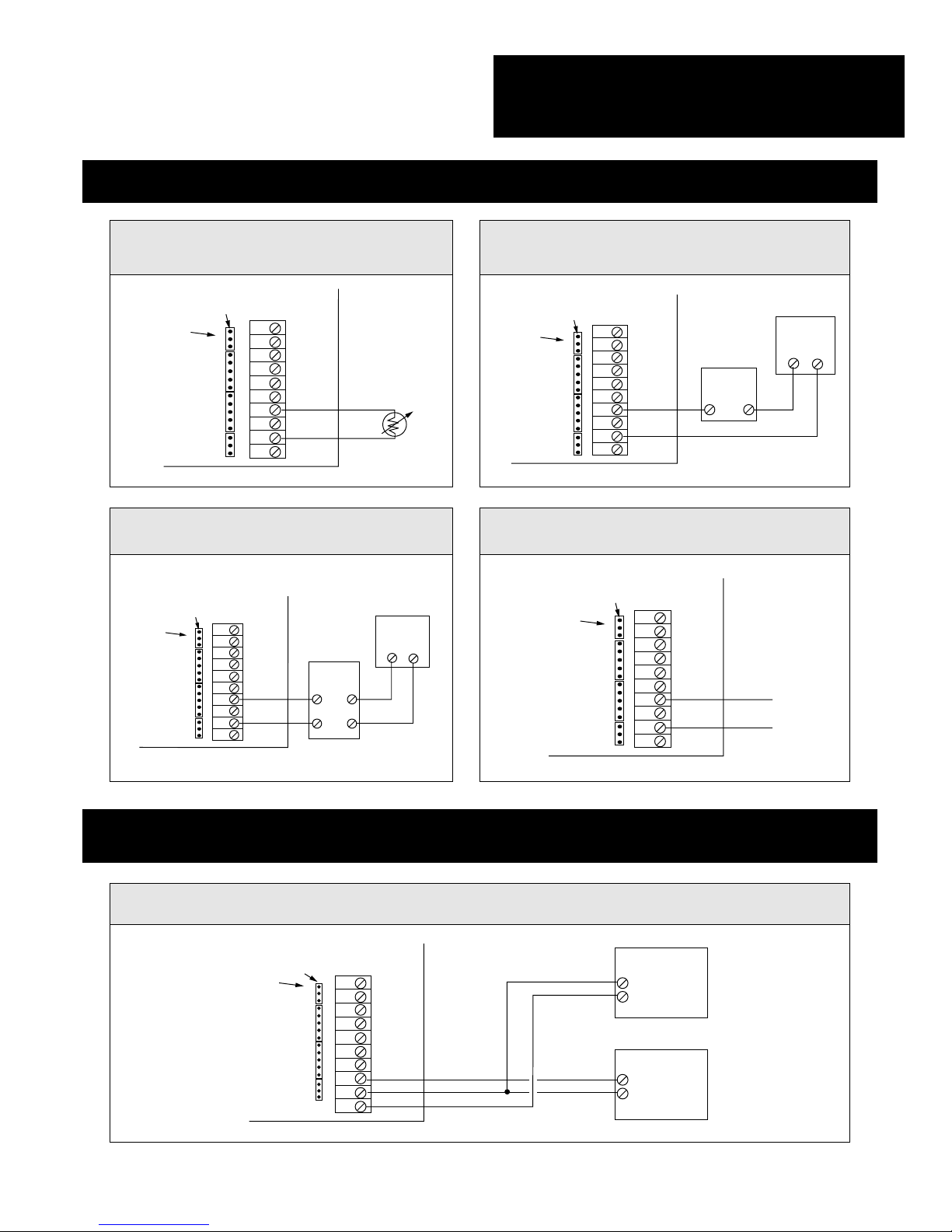
Make all connections according to wiring diagrams and in compliance with national and local codes. Make all con-
nections with power removed. Failure to do so may result in circuit board damage. Shielded cable is recommended
for input and analog setpoint wiring. The shield should be connected to the UCM-420A "common" terminal. At the
opposite end, the shield is not to be connected, and should be taped back. In cases where more wires are required
to be connected to the common terminal block of the UCM-420A than will fit under the screw on the terminal block,
connect as follows:
A. Place the 24 VDC minus power wire directly under the "common" screw.
B. Place one or two short splice wires directly under the "common" screw and tighten screw.
C. Make all required "common" connections to the splice wires using crimp connections or
wire nuts.
Make all wiring connections for local and/or remote setpoint, input, power, and outputs per the General Wiring
Diagrams which follow.
The PWM Remote Setpoint Signal may be powered by the UCM-420A power supply or by a separate power
source. If a separate power source is used, the PWM signal may be 24 VAC or 24 VDC. There is no polarity on the
PWM terminals. Either leg of the PWM signal may be switched by the controller.
(See General Wiring Diagrams 1, 2 & 3.)
REMOTE SETPOINT WIRING - PULSE-WIDTH SETPOINT (DIAGRAMS 1, 2 & 3)
GENERAL WIRING DIAGRAM 1 - Using the UCM-420A power supply for PWM pulse and switching
positive leg of the PWM pulse circuit.
GENERAL WIRING DIAGRAM 2 - Using the UCM-420A power supply for PWM pulse and switching
negative leg of the PWM pulse circuit.
General Wiring
Instructions & Diagrams

5
General Wiring
Diagrams (Cont.)
PWM
INPUT
PWM
INPUT
REM SPT
INPUT
LOC SPT
POT +
LOC SPT
INPUT
LOC SPT
POT –
COMMON
MA SIG
OUTPUT
24 VAC
OR
24 VDC
+
–
24 VAC
OR
24 VDC
+
–
CONTACT AT BAS CONTROLLER
(EITHER LEG MAY BE SWITCHED)
FEEDBK
INPUT
24V PWR
1
2
11
12
JUMPER
POSITION
NUMBER
JUMPER
PINS
7
8
9
10
3
4
5
6
PWM
INPUT
PWM
INPUT
REM SPT
INPUT
LOC SPT
POT +
LOC SPT
INPUT
LOC SPT
POT –
COMMON
MA SIG
OUTPUT
24 VAC
OR
24 VDC
+
–
+
–
4-20 MA REMOTE
SETPOINT SIGNAL
FEEDBK
INPUT
24V PWR
1
2
11
12
JUMPER
POSITION
NUMBER
JUMPER
PINS
7
8
9
10
3
4
5
6
PWM
INPUT
PWM
INPUT
REM SPT
INPUT
LOC SPT
POT +
LOC SPT
INPUT
LOC SPT
POT –
COMMON
MA SIG
OUTPUT
24 VAC
OR
24 VDC
+
–
+
–
1-5 VDC REMOTE
SETPOINT SIGNAL
FEEDBK
INPUT
24V PWR
1
2
11
12
JUMPER
POSITION
NUMBER
JUMPER
PINS
7
8
9
10
3
4
5
6
GENERAL WIRING DIAGRAM 3 - Completely separate PWM and UCM-420A circuits.
REMOTE SETPOINT - ANALOG SETPOINT WIRING (DIAGRAMS 4 & 5)
GENERAL WIRING DIAGRAM 4 - 4-20 mA remote setpoint
GENERAL WIRING DIAGRAM 5 - 1-5 VDC remote setpoint

6
LOCAL SETPOINT WIRING (DIAGRAMS 6-9)
PWM
INPUT
PWM
INPUT
REM SPT
INPUT
LOC SPT
POT +
LOC SPT
INPUT
LOC SPT
POT –
COMMON
MA SIG
OUTPUT
1-5 VDC
LOCAL
SETPOINT
SIGNAL
+
–
FEEDBK
INPUT
24V PWR
1
2
11
12
JUMPER
POSITION
NUMBER
JUMPER
PINS
7
8
9
10
3
4
5
6
PWM
INPUT
PWM
INPUT
REM SPT
INPUT
LOC SPT
POT +
LOC SPT
INPUT
LOC SPT
POT –
COMMON
MA SIG
OUTPUT
4-20 MA
LOCAL
SETPOINT
SIGNAL
+
–
FEEDBK
INPUT
24V PWR
1
2
11
12
JUMPER
POSITION
NUMBER
JUMPER
PINS
7
8
9
10
3
4
5
6
PWM
INPUT
PWM
INPUT
REM SPT
INPUT
LOC SPT
POT +
LOC SPT
INPUT
LOC SPT
POT –
COMMON
MA SIG
OUTPUT
INCREASE SETPOINT
FEEDBK
INPUT
24V PWR
PRECON TWO-WIRE
POTENTIOMETER
("XA" OPTION ON
TEMPERATURE SENSOR)
1
2
11
12
JUMPER
POSITION
NUMBER
JUMPER
PINS
7
8
9
10
3
4
5
6
PWM
INPUT
PWM
INPUT
REM SPT
INPUT
LOC SPT
POT +
LOC SPT
INPUT
LOC SPT
POT –
COMMON
MA SIG
OUTPUT
INCREASE SETPOINT
*WHEN A THREE-WIRE POTENTIOMETER
IS USED, JUMPER PLUGS MUST BE LEFT
OFF POSITIONS 3, 4, 5 AND 6.
FEEDBK
INPUT
24V PWR
THREE-WIRE
POTENTIOMETER
5 KW TO 50 KW
MAXIMUM
RESISTANCE
RED
GREEN
BLACK
1
2
11
12
JUMPER
POSITION
NUMBER
JUMPER
PINS
7
8
9
10
3
4
5
6
GENERAL WIRING DIAGRAM 6 - Using a three-wire potentiometer for local setpoint. (The UCM-420A
is shipped with a three-wire potentiometer mounted and wired per this diagram.)
GENERAL WIRING DIAGRAM 7 - Using a PreCon two-wire potentiometer ("XA" option on a temperature sensor) for local setpoint.
GENERAL WIRING DIAGRAMS 8 & 9 - Using an analog (4-20 mA or 1-5 VDC) signal for local setpoint.
Analog signals are normally used as remote setpoints. However, the UCM-420A may be configured to
accept an analog signal for a local setpoint if this is required.
GENERAL WIRING DIAGRAM 8 -
4-20 mA local setpoint
GENERAL WIRING DIAGRAM 9 -
1-5 VDC local setpoint
General Wiring
Diagrams (Cont.)
PWM
INPUT
PWM
INPUT
REM SPT
INPUT
LOC SPT
POT +
LOC SPT
INPUT
LOC SPT
POT –
COMMON
MA SIG
OUTPUT
1
2
3
4
5
6
7
8
9
10
11
12
JUMPER
POSITION
NUMBER
JUMPER
PINS
24 VAC
OR
24 VDC
+
–
–
+
CONTROLLED
DEVICE
FEEDBK
INPUT
24V PWR
7
General Wiring
Diagrams (Cont.)
INPUT WIRING (DIAGRAMS 10-12)
PWM
INPUT
PWM
INPUT
REM SPT
INPUT
LOC SPT
POT +
LOC SPT
INPUT
LOC SPT
POT –
COMMON
MA SIG
OUTPUT
TWO-WIRE
4-20 MA
DEVICE
– +
+ –
24 VDC
POWER
SUPPLY
FEEDBK
INPUT
24V PWR
1
2
11
12
JUMPER
POSITION
NUMBER
JUMPER
PINS
7
8
9
10
3
4
5
6
PWM
INPUT
PWM
INPUT
REM SPT
INPUT
LOC SPT
POT +
LOC SPT
INPUT
LOC SPT
POT –
COMMON
MA SIG
OUTPUT
1-5 VDC
INPUT
SIGNAL
+
–
FEEDBK
INPUT
24V PWR
1
2
11
12
JUMPER
POSITION
NUMBER
JUMPER
PINS
7
8
9
10
3
4
5
6
PWM
INPUT
PWM
INPUT
REM SPT
INPUT
LOC SPT
POT +
LOC SPT
INPUT
LOC SPT
POT –
COMMON
MA SIG
OUTPUT
PRECON TYPE 3
THERMISTOR
FEEDBK
INPUT
24V PWR
1
2
11
12
JUMPER
POSITION
NUMBER
JUMPER
PINS
7
8
9
10
3
4
5
6
PWM
INPUT
PWM
INPUT
REM SPT
INPUT
LOC SPT
POT +
LOC SPT
INPUT
LOC SPT
POT –
COMMON
MA SIG
OUTPUT
FOUR-WIRE
4-20 MA
DEVICE
+ +
+ –
24 VDC
POWER
SUPPLY
– –
FEEDBK
INPUT
24V PWR
1
2
11
12
JUMPER
POSITION
NUMBER
JUMPER
PINS
7
8
9
10
3
4
5
6
GENERAL WIRING DIAGRAM 10 PreCon Type 3 Thermistor input
GENERAL WIRING DIAGRAM 11B 4-20 mA input from a four-wire device
POWER SUPPLY & OUTPUT WIRING (DIAGRAM 13)
GENERAL WIRING DIAGRAM 13 - Power supply and output wiring
GENERAL WIRING DIAGRAM 11A 4-20 mA input from a two-wire device
GENERAL WIRING DIAGRAM 12 1-5 VDC input signal

8
The UCM-420A is a versatile, low-cost microprocessor-based proportional/integral controller which may be used for a wide variety of control applications.
To select the mode of operation required, please review the descriptions on the following
pages.
EXAMPLE: REMOTE SETPOINT CONTROLLER - Hot Water Reset
In this example, a BAS controller is monitoring outdoor air temperature and sending a time-based pulsewidth signal to the UCM-420A to set the system hot water temperature. By using this control system, the
BAS may also control the hot water temperature based on time of day, minimum space temperature, etc.
The UCM-420A accepts the setpoint signal from the BAS and the input from the hot water temperature
sensor and sends a proportional/integral control signal to the three-way valve to maintain the system hot
water temperature as programmed.
HOT WATER
RESET VALVE
4-20 MA P/I
CONTROL SIGNAL
UCM-420A
HOT WATER SUPPLY
FROM BOILER
PWM REMOTE SETPOINT SIGNAL
4-20 MA TEMPERATURE
INPUT SIGNAL
BAS
CONTROLLER
RTD &
TRANSMITTER
HOT WATER
SUPPLY
TO SYSTEM
HOT WATER
RETURN
FROM SYSTEM
A
Remote Setpoint Controller
When the UCM-420A is used as a remote setpoint controller, a 4-20 mA, 1-5 VDC or time-based pulse-width signal
from a BAS controller sends a setpoint signal to the UCM-420A. The UCM-420A monitors a 4-20 mA, 1-5 VDC, or
thermistor input from the process being controlled to provide a proportional/integral control signal to the controlled
device. This signal may be direct- or reverse-acting. See page 13 for instructions on operating the UCM-420A in
this mode.
Modes of Operation

VFD
UCM-420A
T30-030
AC POWER
IN
STATIC
PRESSURE
TUBING
4-20 MA
P/I
CONTROL
SIGNAL
SUPPLY
AIR
RETURN
AIR
VAV TERMINAL
VAV TERMINAL
VAV TERMINAL
9
When the UCM-420A is used as a local setpoint controller, the potentiometer mounted on the unit may control the
setpoint. If this is not desired, a UCM-SPA setpoint potentiometer or PreCon "XA" Setpoint Option on a temperature sensor may be wired to the "Local Setpoint" terminals as shown in the wiring diagrams. (The local setpoint may
also be configured to accept a 4-20 mA or 1-5 VDC signal, although these signals would normally be used as a
remote setpoint). A 4-20 mA, 1-5 VDC, or thermistor input (with a range of 50 to 90°F)* from the process being controlled allows the UCM-420A to monitor the system and provide a proportional/integral, direct- or reverse-acting
signal to the device being controlled. See page 16 for instructions on operating the UCM-420A in this mode.
*Other ranges available
Local Setpoint Controller
Modes of Operation (Cont.)
EXAMPLE: LOCAL SETPOINT CONTROLLER - Static Pressure Control
In this example, the input to the UCM-420A is a 4-20 mA signal from a pressure transducer that monitors duct pressure. The setpoint is adjusted by using the setpoint potentiometer mounted on the UCM-420A. The UCM-420A then
sends a 4-20 mA control signal to the VFD which controls the AHU fan speed, which in turn, determines duct pressure.
B

10
Remote Setpoint Controller With Local Adjustment
C
When the UCM-420A is used as a remote setpoint controller with local adjustment, a 4-20 mA, 1-5 VDC, or timebased pulse-width signal from a BAS controller sends a setpoint signal to the UCM-420A. The setpoint potentiometer on the UCM-420A or a UCM-SPA setpoint potentiometer wired to the "Local Setpoint" terminals may then
be used to adjust the setpoint ±12.5% of the input range, or a PreCon "XA" Setpoint Option on a temperature
sensor may be used as a local setpoint and may adjust the setpoint ±9.4% of the input range. (A 4-20 mA or 1-5 VDC
signal may also be used as the "Local Setpoint" signal, although these are normally remote setpoint signals. When
these are used as local setpoints in this mode, they have the authority to adjust the setpoint ±12.5% of the input
range.) A 4-20 mA, 1-5 VDC, or thermistor input (with a range of 50 to 90°F)* from the process being controlled
allows the UCM-420A to monitor the system and provide a proportional/integral, direct- or reverse-acting signal to
the device being controlled. See page 18 for instructions on operating the UCM-420A in this mode.
* Other ranges available
EXAMPLE: REMOTE SETPOINT CONTROLLER WITH LOCAL ADJUSTMENT - VAV Control
In this example, a PreCon ST-S3E-XA Thermistor with setpoint adjustment is located in the space being controlled. The setpoint is a 4-20 mA signal from a BAS controller. The PreCon "XA" setpoint adjuster will have
authority to adjust the setpoint ±3.76°F. [(90 to 50°F*) x 0.094 = 3.76°F] In this example, the BAS controller could
be programmed to send a setpoint signal for 72°F (12.8 mA) during the day, 82°F (16.8 mA) at night, etc.
Modes of Operation (Cont.)
BAS
CONTROLLER
SUPPLY
AIR
4-20 MA P/I
CONTROL
SIGNAL
ACT.
VAV
TERMINAL
4-20 MA REMOTE
SETPOINT SIGNAL
UCM-420A
SUPPLY
AIR
THERMISTOR
TEMP INPUT
LOCAL SETPOINT
ADJUST
ST-S3E-XA
TEMPERATURE SENSOR
WITH SETPOINT ADJUST

11
Modes of Operation (Cont.)
SUPPLY
AIR
VAV
TERMINAL
ACT.
SUPPLY
AIR
UCM-420A
ST-S3P
SUPPLY
AIR
VAV
TERMINAL
ACT.
SUPPLY
AIR
UCM-420A
ST-S3P
SUPPLY
AIR
VAV
TERMINAL
ACT.
SUPPLY
AIR
UCM-420A
ST-S3P
TEMPERATURE
SENSOR
4-20 MA P/I
CONTROL
SIGNAL
+
–
CONTROLLER
N.O. PWM
CONTACT
In this example, one time-based
pulse-width output from a BAS controller is used to send a setpoint
signal to three UCM-420A setpoint
controllers. Each of these may have
a different setpoint. Each UCM-420A
also accepts an input from a PreCon
Type 3 Temperature Sensor in the
space being controlled. The
UCM-420As send 4-20 mA proportional/integral control signals to the
VAV terminals so that the input
matches the setpoint. Multiple
UCM-420As may be assigned the
same address so that they have the
same setpoint. Eight different
addresses are available so that up to
eight groups of UCM-420As may be
controlled by one BAS output.
Instructions on setting UCM-420A
addresses and how to update the
setpoint with the BAS pulse-width
signal are on page 22.
EXAMPLE: UCM-420As USED AS OUTPUT EXPANDERS - Multiplexed VAV Control
The UCM-420A may be operated in a multiplexed pulse-width modulation mode so that one BAS output may control
up to eight groups of UCM-420As with each group able to have a different setpoint. When operated in this mode,
each UCM-420A accepts a 4-20 mA, 1-5 VDC, or thermistor input (with a range of 50 to 90°F)* from the process
being controlled. The "PWM INPUT" terminals are wired to the normally open contacts on a BAS controller. The
BAS controller is programmed to send a series of 24 VAC or 24 VDC time-based pulse-width signals to the
UCM-420As. These PWM signals select which units are to be addressed, and adjust their setpoints as required.
The UCM-420As which are not being addressed ignore the new setpoint signal and continue to control based on
their previous setpoint. Each UCM-420A will monitor its input signal and send a P/I control signal to the controlled
device to maintain the required setpoint. When operated in this mode, the local setpoint may also be used to adjust
the setpoint which has been set by the BAS controller. The setpoint potentiometer on the UCM-420A or a UCM-
SPA setpoint potentiometer wired to the "Local Setpoint" terminals may be used to adjust the setpoint ±12.5% of the
input range, or a PreCon "XA" Setpoint Option on a temperature sensor may be used as a local setpoint and may
adjust the setpoint ±9.4% of the input range. (A 4-20 mA or 1-5 VDC signal may also be used as the "Local
Setpoint" signal, although these are normally remote setpoint signals. When these are used as local setpoints in this
mode, they have the authority to adjust the setpoint ±12.5% of the input range.) See page 22 for instructions on
operating the UCM-420A in this mode.
* Other ranges available
D
Output Expander (Multiplexed PWM)

12
If the device to be controlled by the UCM-420A needs to be calibrated before the system is started up, the UCM-420A
may be used to generate a 4-20 mA output signal in 1 mA steps. In this mode the UCM-420A ignores all input and
setpoint signals and outputs a signal from 4-20 mA when DIP switches are turned off or on as required. See Page
29 for instructions on operating the UCM-420A in this mode.
THIS CONCLUDES MODES OF OPERATION. THE FOLLOWING SET-
UP INSTRUCTIONS WILL GUIDE YOU THROUGH THE STEPS NECESSARY TO ACHIEVE THE MODE OF OPERATION YOU REQUIRE.
E
Sample and Hold
The UCM-420A may be used to monitor and pass through a 4-20 mA or 1-5 VDC signal. If the signal being monitored is lost, the UCM-420A will output the last valid value for the signal until the signal returns. On a power loss, the
signal is remembered up to six hours. When used in this mode the UCM-420A may be programmed to either
reverse the signal being monitored, or pass it through direct. See page 26 for instructions on operating the UCM-420A
in this mode.
F
Pulse-Width to 4-20 mA Converter (Single or Multiplexed)
G
4-20 mA Signal Generator
In this mode the UCM-420A converts a time-based pulse-width AC or DC signal to a 4-20 mA output. By using the
multiplexed mode, multiple UCM-420As may be controlled by one BAS output. In this mode all setpoint and input
signals are ignored and the output signal is based on the pulse-width signal only. The output signal is retained up to
6 hours on a loss of power. Upon a power return, the saved value is output until a new pulse signal is received. The
output may be direct- or reverse-acting. See page 27 for instructions on operating the UCM-420A in this mode.
Modes of Operation (Cont.)

If remote setpoint is set for pulse-width modulation, select the pulse-width time base from
TABLE 2. If remote setpoint is by 4-20 mA or 1-5 VDC, proceed to Step A-3.
Mode Switch Switch Switch Switch Set jumper
A1 A2 B1 B2 plugs on
4-20 mA Remote setpoint ON OFF OFF OFF Position 1
1-5 VDC Remote setpoint ON OFF OFF OFF Position 2
PWM Remote setpoint
(no multiplex mode) ON OFF ON OFF Position 1
13
Set-Up Instructions
A
SET-UP OF THE UCM-420A AS A REMOTE SETPOINT
CONTROLLER (SEE PAGE 8)
Set the DIP switches and jumpers as shown in TABLE 1 for the remote setpoint to be used.
FAILSAFE FEATURE
On a loss of power, the remote setpoint value is retained for up to 6 hours. Upon power return on a unit with
PWM remote setpoint, the saved value will be used for control until a new PWM pulse is received.
Upon power return on a unit with analog remote setpoint, the saved value will be used to control until a new
analog setpoint signal is received.
If power is not lost, but the analog remote setpoint signal is suddenly lost (because of a loose wire or
Building Automation System failure), the UCM-420A will continue to control with the previous setpoint until a
valid signal returns.
STEP
A-2
Time base B6 B7 B8
0.1-2.65 seconds OFF OFF OFF
0.1-5.2 seconds OFF OFF ON
0.1-12.85 seconds OFF ON OFF
0.1-25.6 seconds OFF ON ON
0.59-2.93 seconds ON OFF OFF
STEP
A-1
Setpoint = (pulse length) (input range)
+ input lower value
time base
Example: If pulse length is 12.8 sec., time base is 25.6 sec., and the input sensor has a 4-20 mA range of
20° to 120°F, the setpoint could be determined as follows: Setpoint = (12.8) (120-20)
+ 20 = 70.2°F
(25.6 - 0.1)
TABLE 2
TABLE 1

Throttling Range Switch A6 Switch A7 Switch A8
10% OFF OFF OFF
20% OFF OFF ON
35% OFF ON OFF
50% OFF ON ON
65% ON OFF OFF
80% ON OFF ON
90% ON ON OFF
100% ON ON ON
Input Set jumper plugs on
4-20 mA Positions 7 and 11
1-5 VDC Positions 8 and 11
PreCon Type 3 Thermistor Positions 10 and 12
14
Select the type of input to be used and set the jumper per TABLE 3. The input may be a 4-20 mA
or 1-5 volt signal that measures temperature, pressure, humidity, etc., or a PreCon Type 3
Thermistor. If the thermistor is used, the range of the thermistor is 50° to 90°F.*
*Other ranges available
STEP
A-3
TABLE 3
TABLE 4
Set switch A3 in the "ON" position for Direct-Acting Control and in the "OFF" position for
Reverse-Acting Control. (
Direct-Acting Control
is when an increase in the input signal above set-
point causes the output signal to increase.
Reverse-Acting Control
is when an increase in the input
signal above setpoint causes the output signal to decrease.)
STEP
A-4
Set the proportional throttling range per TABLE 4. The throttling range is the amount of signal
change at the input required to cause the output signal to go through its entire range (4-20 mA).
For example, a 20% throttling range means that a 1 mA change in the input causes a 5 mA change
in the output signal. When using the optional thermistor input, a 1°F change in input is the equivalent of 0.4 mA change in the mA input mode. The correct throttling range cannot be calculated, but
must be adjusted for each application. Generally, systems that respond quickly should have a narrower throttling range than systems that respond slowly.
STEP
A-5
Set-Up Instructions (Cont.)

Resets/Minute Switch A4 Switch A5
Reset OFF OFF OFF
0.5 Resets/Minute OFF ON
1 Resets/Minute ON OFF
2 Resets/Minute ON ON
15
PWM
INPUT
PWM
INPUT
REM SPT
INPUT
LOC SPT
POT +
LOC SPT
INPUT
LOC SPT
POT –
FEEDBK
INPUT
24 PWR
COMMON
MA SIG
OUTPUT
1
2
3
4
5
6
7
8
9
10
11
12
B3
0
0
0
0
1
1
1
1
B6
0
0
0
0
1
B7
0
0
1
1
X
B8
0
1
0
1
X
B4
0
0
1
1
0
0
1
1
B5
0
1
0
1
0
1
0
1
MUX
ADDR
1
2
3
4
5
6
7
8
A6
0
0
0
0
1
1
1
1
A7
0
0
1
1
0
0
1
1
A8
0
1
0
1
0
1
0
1
PROP
T.R.
10%
20%
35%
50%
65%
80%
90%
100%
UCM-420A
TIME
BASE
2.65
5.2
12.85
25.6
.59-2.93
A4
0
0
1
1
A5
0
1
0
1
RESET
PER MIN
OFF
0.5
1
2
"1" MEANS
TURN SWITCH ON
"0" MEANS
TURN SWITCH OFF
SWITCH OFF
SWITCH ON
A3
A2
A1
B1
B2
REVERSE ACTING
BOTH OFF >> REMOTE SETPT
SAMPLE AND HOLD MODE
BOTH OFF >> ANALOG
REMOTE SETPOINT
DIRECT ACTING
LOCAL SETPT ENABLE
REMOTE SETPT ENABLE
PWM REM SETPT SGLE UNIT
PWM REM SETPT MUX MODE
LOCAL
SETPOINT
FEEDBACK
REMOTE
SETPOINT
STATUS
B
A
1 2 3 4 5 6 7 8
1 2 3 4 5 6 7 8
24 VAC OR 24 VDC POWER
4-20 MA, 1-5 VOLT OR THERMISTOR INPUT SIGNAL
4-20 MA SOURCING OUTPUT SIGNAL TO
CONTROLLED DEVICE
4-20 MA OR 1-5 VOLT REMOTE SETPOINT SIGNAL
(ONLY IF REMOTE SETPOINT IS ANALOG SIGNAL)
24 VAC OR 24 VDC PWM SIGNAL FROM BAS
(ONLY IF REMOTE SETPOINT IS PWM)
CONTACT AT CONTROLLER*
+
–
+
–
–
+
+
–
+
–
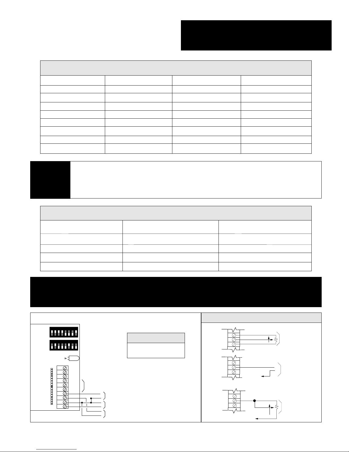
Steady Green - Power On
Dark - Power Loss
Steady Red - PWM Signal Present
WIRING THE UCM-420A AS A REMOTE SETPOINT CONTROLLER
Set the integral reset rate per TABLE 5. The integral reset feature corrects the output of the
UCM-420A to compensate for the offset inherent in proportional-only controllers. The integral reset
ramps the output in the direction that forces the input signal to exactly match the setpoint. The
number of times per minute this offset is overcome by the output signal is the integral reset rate. If
the output of the UCM-420A is used for digital control, set the integral reset "OFF."
STEP
A-6
Set-Up Instructions (Cont.)
TABLE 5
THIS CONCLUDES SET-UP OF THE UCM-420A AS A REMOTE SETPOINT CONTROLLER. WIRE THE UCM-420A PER THE WIRING
DIAGRAM BELOW AND PER GENERAL WIRING DIAGRAMS.
LED INDICATION
*NOTE: PWM contact at controller may switch either positive or negative leg of circuit, and PWM
circuit may use the same power supply as the UCM-420A, or a separate power supply. See the
General Wiring Diagram Section for detailed wiring.

Input Set jumper plugs on
4-20 mA Positions 7 &11
1-5 VDC Positions 8 & 11
PreCon Type 3 Thermistor Positions 10 & 12
Mode Switch Switch Set jumper
A1 A2 plugs on
Three-wire pot Local setpoint OFF ON Position 1 (No jumper on 3-6)
4-20 mA* Local setpoint OFF ON Positions 1 & 3
1-5VDC* Local setpoint OFF ON Positions 1 & 4
Two-wire pot* Local setpoint OFF ON Positions 1 & 6
16
B
SET-UP OF THE UCM-420A AS A LOCAL SETPOINT
CONTROLLER (SEE PAGE 9)
Set the DIP switches and jumpers as shown in TABLE 6 for the local setpoint to be used.
STEP
B-1
TABLE 6
TABLE 7
*UCM-420A comes from the factory with an integral three-wire local setpoint potentiometer. To use any
other local setpoint option, installer must first remove existing three wires from local setpoint terminals on
UCM-420A terminal block.
Select the type of input to be used and set the jumpers per TABLE 7. The input may be a 4-20 mA
or 1-5 volt signal which measures temperature, pressure, humidity, etc. or a PreCon Type 3
Thermistor. If the thermistor is used, the range of the thermistor input is 50 to 90°F.*
*Other ranges available
STEP
B-2
Set switch A3 in the "ON" position for Direct-Acting Control and in the "OFF" position for
Reverse-Acting Control. (
Direct-Acting Control
is when an increase in the input signal above set-
point causes the output signal to increase.
Reverse-Acting Control
is when an increase in the input
signal above setpoint causes the output signal to decrease.)
STEP
B-3
Set the proportional throttling range per TABLE 8. The throttling range is the amount of signal
change at the input required to cause the output signal to go through its entire range (4-20 mA).
For example, a 20% throttling range means that a 1 mA change in the input causes a 5 mA change
in the output signal. When using the optional thermistor input, a 1°F change in input is the equivalent of 0.4 mA change in the mA input mode. The correct throttling range cannot be calculated, but
must be adjusted for each application. Generally, systems that respond quickly should have a narrower throttling range than systems that respond slowly.
STEP
B-4
Set-Up Instructions (Cont.)
Resets/Minute Switch A4 Switch A5
Reset OFF OFF OFF
0.5 Resets/Minute OFF ON
1 Resets/Minute ON OFF
2 Resets/Minute ON ON
Throttling Range Switch A6 Switch A7 Switch A8
10% OFF OFF OFF
20% OFF OFF ON
35% OFF ON OFF
50% OFF ON ON
65% ON OFF OFF
80% ON OFF ON
90% ON ON OFF
100% ON ON ON
17
PWM
INPUT
PWM
INPUT
REM SPT
INPUT
LOC SPT
POT +
LOC SPT
INPUT
LOC SPT
POT –
FEEDBK
INPUT
24 PWR
COMMON
MA SIG
OUTPUT
1
2
3
4
5
6
7
8
9
10
11
12
LOCAL
SETPOINT
FEEDBACK
REMOTE
SETPOINT
STATUS
B
A
24 VAC OR 24 VDC POWER
4-20 MA, 1-5 VOLT OR THERMISTOR INPUT SIGNAL
4-20 MA SOURCING OUTPUT SIGNAL TO
CONTROLLED DEVICE
+
–
–
+
+
–
SEE
LOCAL
SETPOINT
WIRING
OPTIONS
1 2 3 4 5 6 7 8
1 2 3 4 5 6 7 8
WIRING THE UCM-420A AS A LOCAL SETPOINT CONTROLLER
LOCAL SETPOINT WIRING OPTIONS
Steady Green - Power On
Dark - Power Loss
LED INDICATION
TABLE 8
Set the integral reset rate per TABLE 9. The integral reset feature corrects the output of the
UCM-420A to compensate for the offset inherent in proportional-only controllers. The integral reset
ramps the output in the direction that forces the input signal to exactly match the setpoint. The
number of times per minute this offset is overcome by the output signal is the integral reset rate. If
the output of the UCM-420A is used for digital control, set the integral reset rate "OFF."
STEP
B-5
TABLE 9
THIS CONCLUDES SET-UP OF THE UCM-420A AS A LOCAL SETPOINT CONTROLLER. WIRE THE UCM-420A PER THE WIRING DIAGRAM BELOW AND
PER GENERAL WIRING DIAGRAMS.
Set-Up Instructions (Cont.)
LOC SPT POT +
LOC SPT INPUT
LOC SPT POT –
LOC SPT POT +
LOC SPT INPUT
LOC SPT POT –
INCREASE SETPONT
+
–
COMMON
THREE-WIRE POTENTIOMETER
(5KW TO 50 KW )
LOCAL SETPOINT
(FACTORY INSTALLED
ON BASIC MODEL)
4-20 MA OR 1-5 VOLT
LOCAL SETPOINT
LOC SPT POT +
LOC SPT INPUT
LOC SPT POT –
COMMON
INCREASE
SETPONT
TWO-WIRE POTENTIOMETER
LOCAL SETPOINT
("XA OPTION ON
PRECON THERMISTOR)

Setpoint = (pulse length) (input range)
+ input lower value
time base
Example: If pulse length is 12.8 sec., time base is 25.6 sec., and the input sensor has a 4-20 mA range of
20 to 120°F, the setpoint could be determined as follows: Setpoint = (12.8) (120-20)
+ 20 = 70.2°F
(25.6 - 0.1)
Time base Switch B6 Switch B7 Switch B8
0.1-2.65 seconds OFF OFF OFF
0.1-5.2 seconds OFF OFF ON
0.1-12.85 seconds OFF ON OFF
0.1-25.6 seconds OFF ON ON
0.59-2.93 seconds ON OFF OFF
18
C
SET-UP OF THE UCM-420A AS A REMOTE SETPOINT
CONTROLLER WITH LOCAL ADJUSTMENT (SEE PAGE 10)
Set Switch A1 and Switch A2 both in the "ON" position.
STEP
C-1
Set the DIP switches and jumpers as shown in TABLE 10 for the remote setpoint to be used.
STEP
C-2
Remote Setpoint Signal Switch B1 Switch B2 Set jumper plugs on
4-20 mA OFF OFF Position 1
1-5 VDC OFF OFF Position 2
PWM ON OFF Position 1
TABLE 10
TABLE 11
FAILSAFE FEATURE
On a loss of power the remote setpoint value is retained for up to 6 hours. Upon power return on a unit with
PWM remote setpoint, the saved value will be used for control until a new PWM pulse is received. Upon
power return on a unit with analog remote setpoint, the saved value will be used to control until a new
analog setpoint signal is received. If power is not lost, but the analog remote setpoint signal is suddenly lost
(because of a loose wire or Building Automation System failure) the UCM-420A will continue to control with
the previous setpoint until a valid signal returns.
If Remote Setpoint is set for Pulse-Width Modulation, select the pulse-width time base from
TABLE 11. If remote setpoint is by 4-20 mA or 1-5 VDC, proceed to Step C-4.
STEP
C-3
Set-Up Instructions (Cont.)

*NOTE: The UCM-420A comes from the factory with an integral three-wire local setpoint potentiometer installed and wired. To use any other local setpoint option (or three-wire potentiometer
separate from the UCM-420A) installer must first remove the existing three wires from the "LOCAL
SETPOINT" terminals on the UCM-420A.
Input Set jumper plugs on
4-20 mA Positions 7 & 11
1-5 VDC Positions 8 & 11
PreCon Type 3 Thermistor Positions 10 & 12
Local Setpoint Signal Set jumper plugs on
Three-wire pot* local setpoint No jumper on positions 3-6
4-20 mA* local setpoint Position 3
1-5 VDC* local setpoint Position 4
Two-wire* ("XA") pot local setpoint Position 6
19
Set-Up Instructions (Cont.)
Set the DIP switches and jumpers as shown in TABLE 12 for the local setpoint to be used.
STEP
C-4
Select the type of input to be used per TABLE 13. The input may be a 4-20 mA or 1-5 volt signal
which measures temperature, pressure, humidity, etc. or a PreCon Type 3 Thermistor. If the thermistor is used, the range of the thermistor input is 50 to 90° F.*
*Other ranges available
STEP
C-5
Set switch A3 in the "ON" position for Direct-Acting Control and in the "OFF" position for
Reverse-Acting Control. (
Direct-Acting Control
is when an increase in the input signal above the
setpoint causes the output signal to increase.
Reverse-Acting Control
is when an increase in the
input signal above the setpoint causes the output signal to decrease.)
STEP
C-6
TABLE 12
TABLE 13

Resets/Minute Switch A4 Switch A5
Reset OFF OFF OFF
0.5 Resets/Minute OFF ON
1 Resets/Minute ON OFF
2 Resets/Minute ON ON
Throttling range Switch A6 Switch A7 Switch A8
10% OFF OFF OFF
20% OFF OFF ON
35% OFF ON OFF
50% OFF ON ON
65% ON OFF OFF
80% ON OFF ON
90% ON ON OFF
100% ON ON ON
20
Set the proportional throttling range per TABLE 14. The throttling range is the amount of signal
change at the input required to cause the output signal to go through its entire range (4-20 mA).
For example, a 20% throttling range means that a 1 mA change in the input causes a 5 mA change
in the output signal. When using the optional thermistor input, a 1°F change in input is the equivalent of 0.4 mA change in the mA input mode. The correct throttling range cannot be calculated, but
must be adjusted for each application. Generally, systems that respond quickly should have a narrower throttling range than systems that respond slowly.
STEP
C-7
Set the integral reset rate per TABLE 15. The integral reset feature corrects the output of the
UCM-420A to compensate for the offset inherent in proportional-only controllers. The integral reset
ramps the output in the direction which forces the input signal to exactly match the setpoint. The
number of times per minute this offset is overcome by the output signal is the integral reset rate. If
the output of the UCM-420A is used for digital control, set the integral reset rate "OFF."
STEP
C-8
TABLE 14
TABLE 15
THIS CONCLUDES SET-UP OF THE UCM-420A AS A REMOTE SETPOINT
CONTROLLER WITH LOCAL ADJUSTMENT. WIRE THE UCM-420A PER THE
WIRING DIAGRAM BELOW AND PER GENERAL WIRING DIAGRAMS.
Set-Up Instructions (Cont.)
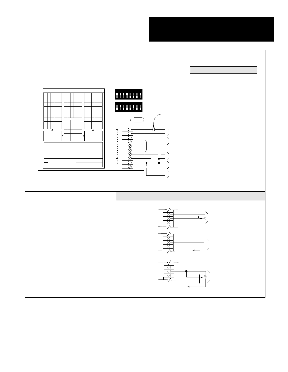
WIRING DIAGRAM - UCM-420A AS A REMOTE SETPOINT CONTROLLER WITH LOCAL ADJUSTMENT
21
LOCAL SETPOINT WIRING OPTIONS
Set-Up Instructions (Cont.)
*NOTE: PWM contact at controller may
switch either positive or negative leg of
circuit, and PWM circuit may use the
same power supply as the UCM-420A
or a separate power supply. See the
General Wiring Diagram Section for
detailed wiring.
Steady Green - Power On
Dark - Power Loss
Steady Red - PWM Signal Present
LED INDICATION
MUX
B3
B4
B5
ADDR
0
0
0
1
0
0
1
2
0
1
0
3
0
1
1
4
1
0
0
5
1
0
1
6
1
1
0
7
1
1
1
8
"1" MEANS
TURN SWITCH ON
SWITCH OFF
A3
REVERSE ACTING
A2
BOTH OFF >> REMOTE SETPT
A1
SAMPLE AND HOLD MODE
B1
BOTH OFF >> ANALOG
B2
REMOTE SETPOINT
UCM-420A
TIME
BASE
B6
B7
B8
2.65
0
0
0
5.2
0
0
1
12.85
0
1
0
25.6
0
1
1
.59-2.93
1
X
X
RESET
PER MIN
A4
A5
OFF
0
0
0.5
0
1
1
1
0
2
1
1
PROP
A6
A7
A8
T.R.
0
0
0
10%
0
0
1
20%
0
1
0
35%
0
1
1
50%
1
0
0
65%
1
0
1
80%
1
1
0
90%
1
1
1
100%
"0" MEANS
TURN SWITCH OFF
SWITCH ON
DIRECT ACTING
LOCAL SETPT ENABLE
REMOTE SETPT ENABLE
PWM REM SETPT SGLE UNIT
PWM REM SETPT MUX MODE
1 2 3 4 5 6 7 8
A
1 2 3 4 5 6 7 8
B
1
2
REMOTE
SETPOINT
3
4
5
6
LOCAL
SETPOINT
7
8
9
10
FEEDBACK
11
12
STATUS
PWM
INPUT
PWM
INPUT
REM SPT
INPUT
LOC SPT
POT +
LOC SPT
INPUT
LOC SPT
POT –
FEEDBK
INPUT
24 PWR
COMMON
MA SIG
OUTPUT
SEE
LOCAL
SETPOINT
WIRING
OPTIONS
CONTACT AT CONTROLLER*
24 VAC OR 24 VDC PWM SIGNAL FROM BAS
+
(ONLY IF REMOTE SETPOINT IS PWM)
–
+
4-20 MA OR 1-5 VOLT REMOTE SETPOINT SIGNAL
–
(ONLY IF REMOTE SETPOINT IS ANALOG SIGNAL)
+
4-20 MA, 1-5 VOLT OR THERMISTOR INPUT SIGNAL
–
4-20 MA SOURCING OUTPUT SIGNAL TO
–
+
CONTROLLED DEVICE
+
24 VAC OR 24 VDC POWER
–
LOC SPT POT +
LOC SPT INPUT
LOC SPT POT –
LOC SPT POT +
LOC SPT INPUT
LOC SPT POT –
LOC SPT POT +
LOC SPT INPUT
LOC SPT POT –
INCREASE SETPONT
COMMON
INCREASE
SETPONT
COMMON
THREE-WIRE POTENTIOMETER
(5KW TO 50 KW )
LOCAL SETPOINT
(FACTORY INSTALLED
ON BASIC MODEL)
+
4-20 MA OR 1-5 VOLT
LOCAL SETPOINT
–
TWO-WIRE POTENTIOMETER
LOCAL SETPOINT
("XA OPTION ON
PRECON THERMISTOR)

Multiplex Address Switch B3 Switch B4 Switch B5
1 OFF OFF OFF
2 OFF OFF ON
3 OFF ON OFF
4 OFF ON ON
5 ON OFF OFF
6 ON OFF ON
7 ON ON OFF
8 ON ON ON
Mode Switch A1 Switch A2 Switch B1 Switch B2 Set jumper plugs on
MUX Remote setpoint,
no local setpoint ON OFF OFF ON NONE
MUX Remote setpoint,
4-20 mA local setpoint ON ON OFF ON Positions 1 & 3
MUX Remote setpoint,
1-5V local setpoint ON ON OFF ON Positions 1 & 4
MUX Remote setpoint, Position 1
three-wire local setpoint ON ON OFF ON (no jumper on 3-6)
MUX Remote setpoint,
two-wire local setpoint ON ON OFF ON Positions 1 & 6N
22
Select either a multiplexed remote setpoint with no local adjustment or a multiplexed remote setpoint with local adjustment and set DIP switches and jumpers per TABLE 16. If remote and local
setpoints are both enabled, the remote setpoint establishes the setpoint and the local setpoint has
±12.5% of the input adjustment around this point. If the local setpoint adjustment is by a PreCon
Two-Wire Potentiometer (as used in the “XA” option on PreCon Temperature Sensors) the local
setpoint adjustment is ±9.4% instead of ±12.5%.
STEP
D-1
In the multiplexed PWM mode, each UCM-420A is assigned an address 1-8 so that it may be independently updated by the Building Automation System. Multiple UCM-420As may be assigned the
same address. Assign each UCM-420A an address per TABLE 17. All UCM-420As with the same
address must have the same setpoint.
STEP
D-2
TABLE 16
TABLE 17
D
SET-UP OF THE UCM-420A AS AN OUTPUT EXPANDER WITH
MULTIPLEXED PWM INPUT (SEE PAGE 11)
Set-Up Instructions (Cont.)

Address 2.65 sec* 5.2 sec 12.85 sec 25.6 sec
time base time base time base time base
1 0.2 0.4 0.9 1.6
2 0.6 1.0 2.5 4.8
3 0.9 1.7 4.1 8
4 1.2 2.3 5.7 11.2
5 1.5 3.0 7.3 14.4
6 1.9 3.6 8.9 17.6
7 2.2 4.3 10.5 20.9
8 2.5 4.9 12.1 24
* The 2.65 second time base is not recommended for the MUX mode unless the BAS guarantees an
accuracy of 0.05 seconds or better on its PWM output.
MULTIPLEXED OPERATION
The pulse-width input is optoisolated and can accept an 24 VAC or 24 VDC signal from any source with or
without a common ground. The sequence for updating a UCM-420A setpoint in the multiplexed mode is as
follows:
1. The BAS Controller sends an “Attention” pulse which is one second longer than the maximum pulse for
the time base selected.
2. The BAS Controller then sends a “Select” pulse of one of eight possible time periods to select which
UCM-420A address’s to be updated. See TABLE 19 for the “Address” pulse times for the different time
bases. The UCM-420As which receive a “Select” pulse which matches their address then wait for a setpoint pulse. All other UCM-420As ignore the setpoint pulse and return to the normal operating mode.
3. The BAS Controller then sends the new “Setpoint” pulse to the UCM-420A which has been selected.
The UCM-420A accepts the new setpoint and returns to the normal operating mode. Multiple
UCM-420As may be assigned the same address. In this case, all UCM-420As with the selected address
will receive the new setpoint. Setpoint = pulse length (input range)
+ input lower value
time base
Example: If pulse length is 12.8 sec., time base is 25.6 sec., and the input sensor has a 4-20 mA range of
20 to 120°F, the setpoint could be determined as follows: Setpoint = 12.8 (120-20)
+20 = 70.2°F
(25.6 - 0.1)
Time base B6 B7 B8
0.1-2.65 seconds OFF OFF OFF
0.1-5.2 seconds OFF OFF ON
0.1-12.85 seconds OFF ON OFF
0.1-25.6 seconds OFF ON ON
23
Set-Up Instructions (Cont.)
Select the pulse-width time base per TABLE 18 and set each UCM-420A for the time base
required. The 2.65 second time base is not recommended for multiplexed operation unless the
BAS controller guarantees an accuracy of 0.05 seconds or better on its PWM output.
STEP
D-3
TABLE 18
TABLE 19

SETTING THROTTLING RANGE
Throttling Range Switch A6 Switch A7 Switch A8
10% OFF OFF OFF
20% OFF OFF ON
35% OFF ON OFF
50% OFF ON ON
65% ON OFF OFF
80% ON OFF ON
90% ON ON OFF
100% ON ON ON
Input Set jumper plugs on
4-20 mA Positions 7 & 11
1-5 VDC Positions 8 & 11
PreCon Type 3 Thermistor Positions 10 & 12
24
Select the type of input to be used and set jumpers per TABLE 20. The input may be a 4-20 mA or
1-5V signal which measures temperature, pressure, humidity, etc. or a PreCon Type 3 Thermistor.
STEP
D-4
Set switch A3 in the “ON” position for DIrect-Acting Control and in the “OFF” position for
Reverse-Acting Control. (
Direct-Acting Control
is when an increase in the input signal above set-
point causes the output signal to increase.
Reverse-Acting Control
is when an increase in the input
signal above setpoint causes the output signal to decrease.
STEP
D-5
Set the proportional throttling range per TABLE 21. The throttling range is the amount of signal
change of the input required to cause the output signal to go through its entire range (4-20 mA).
For example, a 20% throttling range means that a 1 mA change in the input signal causes a 5 mA
change in the output signal. When using the optional thermistor input, a 1°F change in input is the
equivalent of 0.4 mA change in the mA input mode. The correct throttling range cannot be calculated, but must be adjusted for each application. Generally, systems that respond quickly should
have a narrower throttling range than systems that respond slowly.
STEP
D-6
TABLE 20
TABLE 21
Set-Up Instructions (Cont.)

Resets/Minute Switch A4 Switch A5
Reset OFF OFF OFF
0.5 Resets/Minute OFF ON
1 Reset/Minute ON OFF
2 Resets/Minute ON ON
25
PWM
INPUT
PWM
INPUT
REM SPT
INPUT
LOC SPT
POT +
LOC SPT
INPUT
LOC SPT
POT –
COMMON
MA SIG
OUTPUT
1
2
3
4
5
6
7
8
9
10
11
12
B3
0
0
0
0
1
1
1
1
B6
0
0
0
0
1
B7
0
0
1
1
X
B8
0
1
0
1
X
B4
0
0
1
1
0
0
1
1
B5
0
1
0
1
0
1
0
1
MUX
ADDR
1
2
3
4
5
6
7
8
A6
0
0
0
0
1
1
1
1
A7
0
0
1
1
0
0
1
1
A8
0
1
0
1
0
1
0
1
PROP
T.R.
10%
20%
35%
50%
65%
80%
90%
100%
UCM-420A
TIME
BASE
2.65
5.2
12.85
25.6
.59-2.93
A4
0
0
1
1
A5
0
1
0
1
RESET
PER MIN
OFF
0.5
1
2
"1" MEANS
TURN SWITCH ON
"0" MEANS
TURN SWITCH OFF
LOCAL
SETPOINT
FEEDBACK
REMOTE
SETPOINT
STATUS
24 VAC OR 24 VDC POWER
4-20 MA, 1-5 VOLTS OR THERMISTOR INPUT SIGNAL
4-20 MA SOURCING OUTPUT SIGNAL TO
CONTROLLED DEVICE
24 VAC OR 24 VDC PWM SIGNAL FROM BAS
(ONLY IF REMOTE SETPOINT IS PWM)
CONTACT AT CONTROLLER*
+
–
–
+
+
–
+
–
SEE
LOCAL
SETPOINT
WIRING
OPTIONS
FEEDBK
INPUT
24 PWR
SWITCH OFF
SWITCH ON
A3
A2
A1
B1
B2
REVERSE ACTING
BOTH OFF >> REMOTE SETPT
SAMPLE AND HOLD MODE
BOTH OFF >> ANALOG
REMOTE SETPOINT
DIRECT ACTING
LOCAL SETPT ENABLE
REMOTE SETPT ENABLE
PWM REM SETPT SGLE UNIT
PWM REM SETPT MUX MODE
B
A
1 2 3 4 5 6 7 8
1 2 3 4 5 6 7 8
Steady Green - Power On
Dark - Power Loss
Steady Red - PWM Signal Present
Slow Green Blink - Attention Mode, No PWM Signal
Slow Red/Green Blink - Attention Mode, PWM Signal Present
Rapid Green Blink - Select Mode, No PWM Signal
Rapid Red/Green Blink - Select Mode, PWM Signal Present
LED INDICATION
Set-Up Instructions (Cont.)
Set the integral reset rate per TABLE 22. The integral reset feature corrects the output of the
UCM-420A to compensate for the offset inherent in proportional controllers. The integral reset
ramps the output in the direction that forces the input signal to exactly match the setpoint. The
number of times per minute this offset is overcome by the output signal is the integral reset rate. If
the output of the UCM-420A is used for digital control, set the integral reset rate “OFF.”
STEP
D-8
TABLE 22
THIS CONCLUDES SET-UP OF THE UCM-420A AS AN OUTPUT EXPANDER
(MUX OPERATION). WIRE THE UCM-420A PER THE WIRING DIAGRAM
BELOW AND PER GENERAL WIRING DIAGRAMS.
*NOTE: PWM contact at controller may switch either positive or negative leg of circuit, and PWM
circuit may use the same power supply as the UCM-420A or a separate power supply. See the
General Wiring Diagram Section for detailed wiring.
WIRING OF THE UCM-420 AS AN OUTPUT EXPANDER (MUX OPERATIONS)

Signal Monitored Set jumper plugs on
4-20 mA Positions 1, 7, & 11
1-5 VDC Positions 2, 7, & 11
26
PWM
INPUT
PWM
INPUT
REM SPT
INPUT
LOC SPT
POT +
LOC SPT
INPUT
LOC SPT
POT –
COMMON
MA SIG
OUTPUT
1
2
3
4
5
6
7
8
9
10
11
12
B3
0
0
0
0
1
1
1
1
B6
0
0
0
0
1
B7
0
0
1
1
X
B8
0
1
0
1
X
B4
0
0
1
1
0
0
1
1
B5
0
1
0
1
0
1
0
1
MUX
ADDR
1
2
3
4
5
6
7
8
A6
0
0
0
0
1
1
1
1
A7
0
0
1
1
0
0
1
1
A8
0
1
0
1
0
1
0
1
PROP
T.R.
10%
20%
35%
50%
65%
80%
90%
100%
UCM-420A
TIME
BASE
2.65
5.2
12.85
25.6
.59-2.93
A4
0
0
1
1
A5
0
1
0
1
RESET
PER MIN
OFF
0.5
1
2
"1" MEANS
TURN SWITCH ON
"0" MEANS
TURN SWITCH OFF
LOCAL
SETPOINT
FEEDBACK
REMOTE
SETPOINT
STATUS
B
A
24 VAC OR 24 VDC POWER
OUTPUT SIGNAL
TO SYSTEM
+
–
+
–
INPUT SIGNAL
MONITORED
–
+
1 2 3 4 5 6 7 8
1 2 3 4 5 6 7 8
FEEDBK
INPUT
24 PWR
SWITCH OFF
SWITCH ON
A3
A2
A1
B1
B2
REVERSE ACTING
BOTH OFF >> REMOTE SETPT
SAMPLE AND HOLD MODE
BOTH OFF >> ANALOG
REMOTE SETPOINT
DIRECT ACTING
LOCAL SETPT ENABLE
REMOTE SETPT ENABLE
PWM REM SETPT SGLE UNIT
PWM REM SETPT MUX MODE
WIRING OF THE UCM-420A IN THE SAMPLE AND HOLD MODE
Steady Green - Signal O.K.
Dark - Power Loss
Steady Red - Signal Lost, Output Being Held
Slow Red/Green Blink - Signal Changing Rapidly.
Output Being Held
LED INDICATION
For Direct-Acting Output (4-20 mA in and 4-20 mA out or 1-5 VDC in and 1-5 VDC out) switch A3
and A4 should be “ON” and all other switches ”OFF”. For Reverse Acting Output (4-20 mA in and
20-4 mA out or 1-5 VDC in and 5-1 VDC out) switch A4 should be “ON” and all other switches “OFF.”
STEP
E-1
Set the jumpers as shown in TABLE 23 for the signal being monitored.
STEP
E-2
D
SET-UP OF THE UCM-420A IN THE SAMPLE AND HOLD
MODE (SEE PAGE 12)
TABLE 23
OPERATION
The UCM-420A may be used to sample an analog signal and hold the value on a loss of signal. In this mode of
operation, the analog remote setpoint signal is sampled and the local setpoint and input signals are ignored. The
“lost” threshold for the sampled signal is 3.2 mA or 0.8 volts.
The remote setpoint signal is sampled once per second. If the new value is within 6% of the previous reading, the
new value is passed through to the output.
If the new sample of the signal is more than 6% higher or lower than the previous sample but is not “lost” (the input
signal is moving), the old output value is held. The new sample is then saved for comparison against the next
sample. When the input signal stops moving so that two consecutive samples are within 6% of each other, the
output updates.
When the newest sample of the signal drops below the “lost” threshold value, the old value is held at the current
output.
On power loss, the current output value is remembered up to 6 hours. On power return, if the sampled signal is
“lost,” the old value will be output until a good signal is received.
Set-Up Instructions (Cont.)

Time base B6 B7 B8
0.1-2.65 seconds OFF OFF OFF
0.1-5.2 seconds OFF OFF ON
0.1-12.85 seconds OFF ON OFF
0.1-25.6 seconds OFF ON ON
0.59-2.93 seconds ON ON ON
Mode Switch Switch Switch Switch
A1 A2 B1 B2
Single Unit PWM OFF OFF ON OFF
Multiplexed PWM OFF OFF OFF ON
27
Set-Up Instructions (Cont.)
The UCM-420A may be used to convert a time-based pulse-width AC or DC input signal to a 4-20
mA output signal. By using the multiplexed mode, multiple UCM-420As may be controlled by one
BAS output. In this mode, the UCM-420A output is based solely on the pulse-width signal and
selected time base. Remote setpoint, local setpoint and input are ignored. The output value is
retained up to 6 hours on a loss of power. Upon power return, the saved value is output until a new
pulse signal is received. The output may be direct- or reverse-acting. Select single unit PWM or
multiplexed PWM by setting the switches as shown in TABLE 24.
STEP
F-1
Select the time base for the control signal by setting DIP switches per TABLE 25.
STEP
F-2
If the output is to be Direct-Acting, switch A3 is to be in the “ON” position. If the output is to be
Reverse-Acting, A3 is to be in the “OFF” position. In the
Direct-Acting mode
, the minimum pulse
input causes a 4 mA output signal. As the length of the pulse-width input signal is increased, the
output signal will increase. In the
Reverse-Acting mode
, the minimum pulse input causes a 20 mA
output signal. As the length of the pulse-width input signal is increased, the output signal will
decrease.
STEP
F-3
If the UCM-420As are to be multiplexed, set the address of each unit from TABLE 26. Multiple
units may have the same address.
STEP
F-4
TABLE 25
F
SET-UP OF THE UCM-420A AS A PULSE WIDTH TO 4-20 MA
CONVERTER (SEE PAGE 12)
TABLE 24

See "Multiplexed Operation" on
page 11 for a description of the
UCM-420A operation in the
multiplexed mode.
Multiplex Address Switch B3 Switch B4 Switch B5
1 OFF OFF OFF
2 OFF OFF ON
3 OFF ON OFF
4 OFF ON ON
5 ON OFF OFF
6 ON OFF ON
7 ON ON OFF
8 ON ON ON
PWM
INPUT
PWM
INPUT
REM SPT
INPUT
LOC SPT
POT +
LOC SPT
INPUT
LOC SPT
POT –
COMMON
MA SIG
OUTPUT
1
2
3
4
5
6
7
8
9
10
11
12
B3
0
0
0
0
1
1
1
1
B6
0
0
0
0
1
B7
0
0
1
1
X
B8
0
1
0
1
X
B4
0
0
1
1
0
0
1
1
B5
0
1
0
1
0
1
0
1
MUX
ADDR
1
2
3
4
5
6
7
8
A6
0
0
0
0
1
1
1
1
A7
0
0
1
1
0
0
1
1
A8
0
1
0
1
0
1
0
1
PROP
T.R.
10%
20%
35%
50%
65%
80%
90%
100%
UCM-420A
TIME
BASE
2.65
5.2
12.85
25.6
.59-2.93
A4
0
0
1
1
A5
0
1
0
1
RESET
PER MIN
OFF
0.5
1
2
"1" MEANS
TURN SWITCH ON
"0" MEANS
TURN SWITCH OFF
LOCAL
SETPOINT
FEEDBACK
REMOTE
SETPOINT
STATUS
24 VAC OR 24 VDC POWER
4-20 MA SOURCING OUTPUT SIGNAL TO
CONTROLLED DEVICE
24 VAC OR 24 VDC PWM SIGNAL FROM BAS
(ONLY IF REMOTE SETPOINT IS PWM)
CONTACT AT CONTROLLER*
–
+
+
–
+
–
FEEDBK
INPUT
24 PWR
SWITCH OFF
SWITCH ON
A3
A2
A1
B1
B2
REVERSE ACTING
BOTH OFF >> REMOTE SETPT
SAMPLE AND HOLD MODE
BOTH OFF >> ANALOG
REMOTE SETPOINT
DIRECT ACTING
LOCAL SETPT ENABLE
REMOTE SETPT ENABLE
PWM REM SETPT SGLE UNIT
PWM REM SETPT MUX MODE
B
A
1 2 3 4 5 6 7 8
1 2 3 4 5 6 7 8
*NOTE: PWM contact
at controller may
switch either positive or negative leg
of circuit, and PWM
circuit may use the
same power supply
as the UCM-420A or
a separate power
supply. See the
General Wiring
Diagram Section for
detailed wiring.
28
STEP F-5
THIS CONCLUDES THE SET-UP OF THE UCM-420A AS A PULSE WIDTH TO
4-20 MA CONVERTER. WIRE THE UCM-420A PER THE WIRING DIAGRAM
BELOW AND THE GENERAL WIRING DIAGRAMS.
WIRING OF THE UCM-420A AS A PWM TO 4-20 mA CONVERTER
TABLE 27
See page 25 for LED indication in MUX
Mode
Steady Green - Power On
Dark - Power Loss
Steady Red - PWM Signal Present
LED INDICATION (No MUX)
TABLE 26
Set-Up Instructions (Cont.)
20 MA
16 MA
12 MA
8 MA
4 MA
0.1
0.1
0.1
0.1
0.59
This table provides the output signal
corresponding to various input pulses
for the different time bases available.
0.66
1.3
3.21
6.4
1.18
1.33
2.6
6.43
12.8
1.76
1.99
3.9
9.64
38.4
4.69
2.65
5.2
12.85
25.6
2.93

29
Set-Up Instructions (Cont.)
Remove power from the UCM-420A.
STEP
G-1
Set all sixteen DIP switches in the "OFF" position.
STEP
G-2
Power up the unit. The status LED will flash RED and the output will go to 4 mA.
STEP
G-3
Any even mA value can then be output by turning on the DIP switch shown in TABLE 28. The
UCM-420A will output a signal for the highest value switch that is turned on; the status of lower
value switches makes no difference. For example, if all switches are off except A6 and A5, the
UCM-420A will output the value for A6 which is 10 mA.
STEP
G-4
Dark - Power Loss
Slow Red Blink - Signal Generator
Mode Selected
LED INDICATION
G
SET-UP OF THE UCM-420A AS A SIGNAL GENERATOR
(SEE PAGE 12)
The UCM-420A may be used as a 4-20 mA signal generator with no input or setpoint signals. This allows equipment
driven by the UCM-420A to be calibrated before system start-up. This mode of operation supplies a 4-20 mA signal in
1 mA steps. If the UCM-420A is installed when the signal generator mode is to be used, wiring should be done in
accordance with the proper wiring diagram for the mode of operation for which the UCM-420A is to be used. If the
UCM-420A is not installed when the signal generator mode is to be used, wire per the wiring diagram below.
WIRING OF THE UCM-420A AS A 4-20 MA SIGNAL GENERATOR
PWM
INPUT
PWM
INPUT
REM SPT
INPUT
LOC SPT
POT +
LOC SPT
INPUT
LOC SPT
POT –
COMMON
MA SIG
OUTPUT
1
2
3
4
5
6
7
8
9
10
11
12
B3
0
0
0
0
1
1
1
1
B6
0
0
0
0
1
B7
0
0
1
1
X
B8
0
1
0
1
X
B4
0
0
1
1
0
0
1
1
B5
0
1
0
1
0
1
0
1
MUX
ADDR
1
2
3
4
5
6
7
8
A6
0
0
0
0
1
1
1
1
A7
0
0
1
1
0
0
1
1
A8
0
1
0
1
0
1
0
1
PROP
T.R.
10%
20%
35%
50%
65%
80%
90%
100%
UCM-420A
TIME
BASE
2.65
5.2
12.85
25.6
.59-2.93
A4
0
0
1
1
A5
0
1
0
1
RESET
PER MIN
OFF
0.5
1
2
"1" MEANS
TURN SWITCH ON
"0" MEANS
TURN SWITCH OFF
LOCAL
SETPOINT
FEEDBACK
REMOTE
SETPOINT
STATUS
24 VAC OR 24 VDC POWER
4-20 MA SIGNAL
OUTPUT
+
–
FEEDBK
INPUT
24 PWR
SWITCH OFF
SWITCH ON
A3
A2
A1
B1
B2
REVERSE ACTING
BOTH OFF >> REMOTE SETPT
SAMPLE AND HOLD MODE
BOTH OFF >> ANALOG
REMOTE SETPOINT
DIRECT ACTING
LOCAL SETPT ENABLE
REMOTE SETPT ENABLE
PWM REM SETPT SGLE UNIT
PWM REM SETPT MUX MODE
B
A
12345678
12345678

UCM-420A Basic model including thermistor input and built-in local setpoint potentiometer
UCO-47 DIN rail mount (mounts on DIN 3F)
UCM-SPA Local setpoint potentiometer on stainless steel plate
DIP switch mA Output
All OFF 4
A1 5
A2 6
A3 7
A4 8
A5 9
A6 10
A7 11
A8 12
DIP switch mA Output
B1 13
B2 14
B3 15
B4 16
B5 17
B6 18
B7 19
B8 20
30
TABLE 28
ORDERING INFORMATION
The standard unit stocked by Kele is the UCM-420A which includes a local setpoint potentiometer and accepts a
thermistor input. On large quantities (100 minimum), special configurations are available. Contact Kele for special
pricing.
Set-Up Instructions (Cont.)
Ordering Information

Post Office Box 34817 (Zip: 38184)
2975 Brother Blvd.
Memphis, Tennessee 38133
Phone: 901-382-4300 Fax: 901-372-2531
TM
 Loading...