

Page 1
QuNexus Editor Manual
MAC:
● An Intel Core 2 Duo 2.3GHz or
greater
● Mac OS 10.5 or later
● 50MB free hard disk space
WINDOWS:
● Windows XP, or Windows 7 & 8
● Intel Core 2 processor or greater
● 1GB of RAM with 50MB free hard disk
space
QuNexus Version 1.1.1
July, 2013
The QuNexus Editor is a free application that we provide on our website. It allows you to create
customized Presets and load them onto QuNexus. This chapter will guide you through
everything you need to know to acquire and operate the QuNexus Editor.
System Requirements
We recommend the following minimum system requirements for the QuNexus Editor:
Installing the Software
For those who wish to customize QuNexus, download our free QuNexus Editor Installer from:
http://www.keithmcmillen.com/QuNexus/downloads/. This comes with the QuNexus Editor and
Documentation.
Installer Instructions (Mac)
1. Double-click on the .dmg file to open the disk image, and then drag the QuNexus
directory into the Applications Alias.
2. A QuNexus folder will now appear in your Applications folder.
Installer Instructions (Windows XP, 7, & 8)
1. Extract the directory from the .zip file and place at a location of your choosing.
2. In order for the application to access everything it needs to run, do not move anything
out of the directory.
1
Page 2
Updating the Firmware
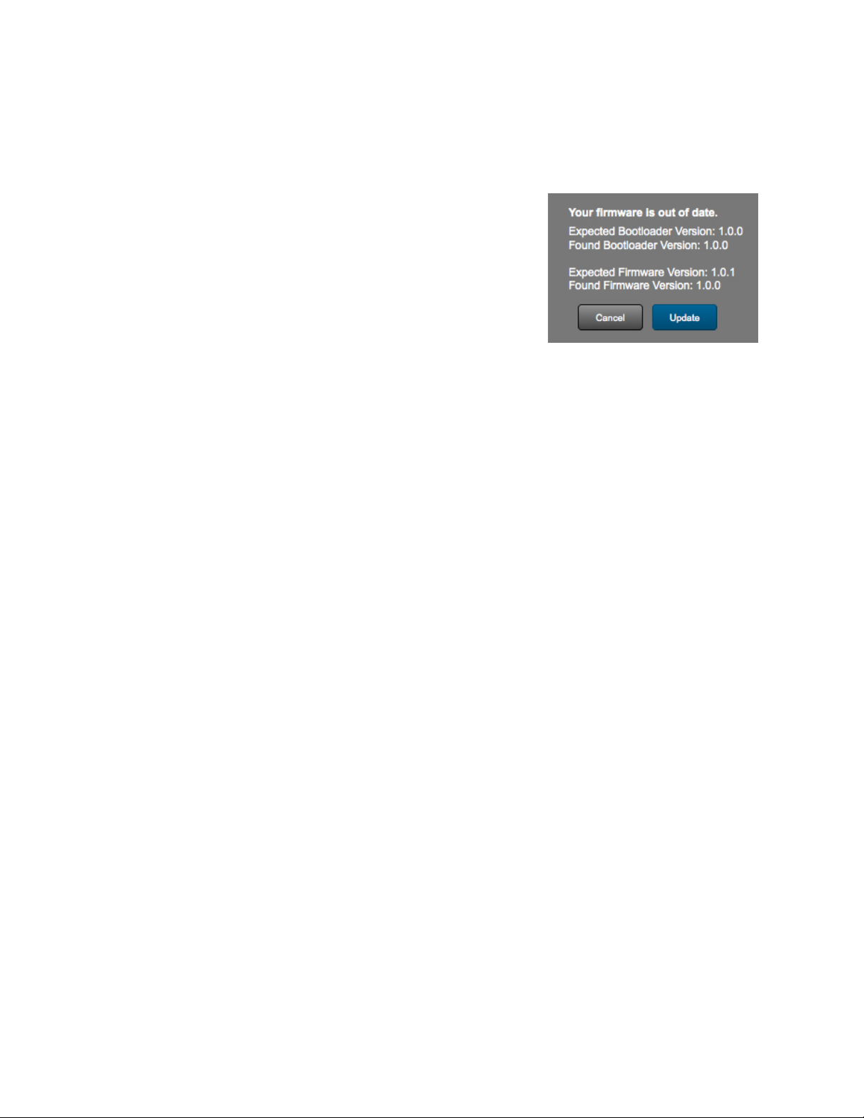
When the QuNexus Editor opens, it checks to make sure the
firmware on the device is compatible with the application. If the
firmware is not compatible, an update prompt will appear. Click
ok and wait until the blue Shift button light stops flashing. The
blue light and progress bar on screen indicate that the firmware
update is in progress.
Make sure the editor and the firmware versions are compatible with each other.
An “Update Firmware” option is located in the Hardware Menu of the QuNexus Editor. Select
this option to force a firmware update.
Keith McMillen Instruments cannot be held liable for damage resulting from installation
and operation errors or improper use.
2
Page 3
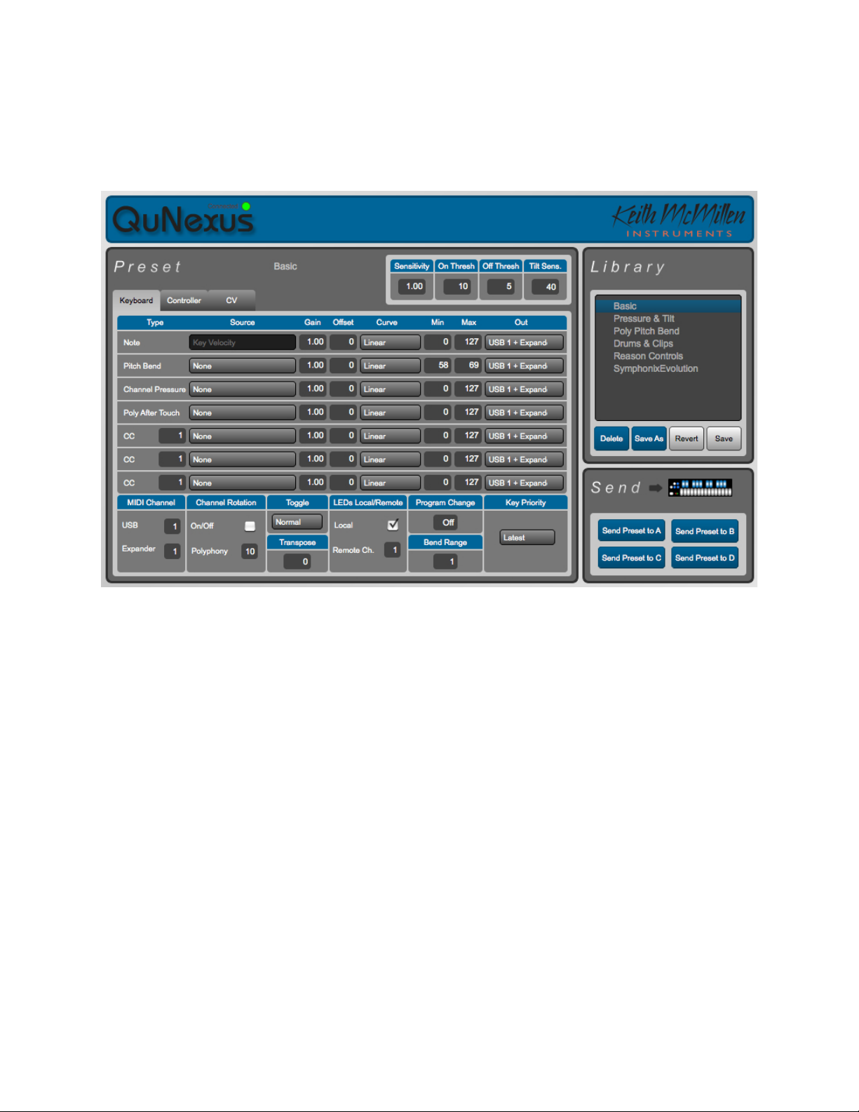
Main Window Overview
The QuNexus Editor opens with this window:
Customize the QuNexus output and input using the Keyboard, Controller, and CV tabs (Layers).
Just above the right side of the tabbed box are the global sensitivity settings to control Gain, On
Threshold, Off Threshold, and Tilt Sensitivity for the QuNexus keys. Controls for saving and
recalling presets are found on the right side of the window. There are tabs for editing Keyboard
Layer, Controller Layer, and CV Layer. Keyboard Layer is the main space for editing the
behavior of the keyboard. Controller Layer allows you to assign additional Notes and individual
Pressure and Tilt CC#s for each Key. CV Layer is for editing the CV input and output.
3
Page 4
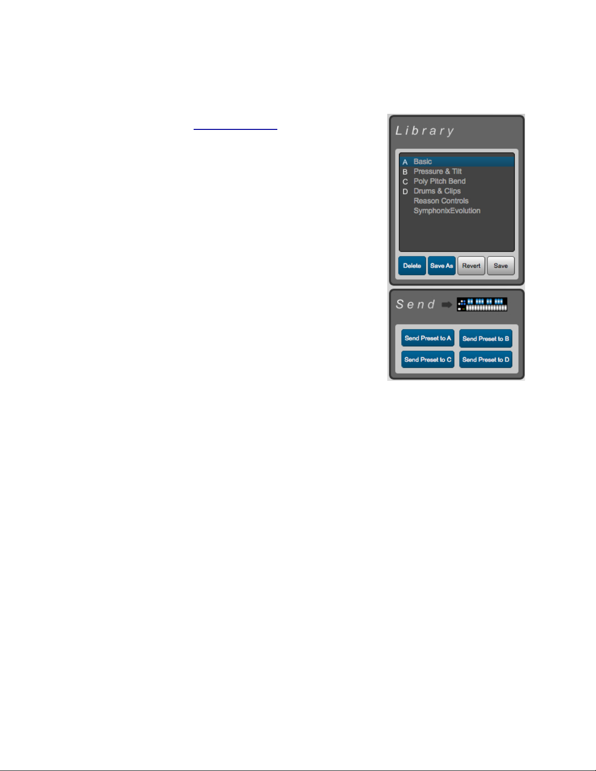
Saving Presets
Select presets by clicking on them in the Library. There are four
Factory Presets (see the QuNexus Presets chapter below for
descriptions of each one).
After clicking a Preset, the name of it will appear above the tabs.
Now you can make changes to the Preset. The Preset name will
turn red and an asterisk will appear next to it to indicate it has
unsaved changes. You can use the Revert button or the Save
button under the Preset Library to discard or keep your changes.
The Revert button will go back to the previously saved version of
the preset.
The Delete and Save As buttons under the Preset Library allow
you to add or remove presets. Copy/Add a Preset by first
selecting the preset you wish to copy and then clicking the Save
As button. You can name it and it will be added to the bottom of
the Library.
To send any of the Presets in the Library down to the QuNexus,
click on the Preset in the Library and use the buttons in the Send
box (shown to the right) to send it to any of the four Preset slots. If
the Preset has any unsaved changes you must save them before
sending them to the QuNexus. The Library will display which
Presets are in which slots on the QuNexus.
To select a preset on the QuNexus, hit the Shift/Preset button to go into preset select mode.
Then hit A, B, C, or D to select the desired preset slot.
QuNexus Presets
Basic (Preset A) - The Basic preset functions as a traditional MIDI keyboard and will work with
any MIDI-enabled software. Though some of the more exciting functions are turned off, the
basic preset outputs notes with a variable velocity and is a great starting point when working
with QuNexus!
● MIDI outputs on Channel 1 through USB and MIDI Expander.
● Velocity is on.
● Local LED Control is on.
● Channel Rotation is off.
● Pitch Bend Range is set to 2 semitones.
● Controller Layer is not active on any keys.
● Control Voltage (CV) output and input are enabled with pitch, gate, and bend all being
sent out of the CV outputs.
4
Page 5

Press & Tilt (Preset B) - The Press and Tilt preset was designed for a wide variety of synths,
apps, and plugins with pitch bend and modulation functionality. This preset maps QuNexus’ key
tilt to pitch bend, and pressure sensitivity to the modulation parameter in most synths. Right out
of the box, most iOS music apps -- like Animoog, Sunrizer and Magellan -- will work with this
preset, allowing for a more exciting and expressive playing experience!
● MIDI outputs on Channel 1 through USB and MIDI Expander.
● Velocity is on.
● Local LED Control is on.
● Channel Rotation is off.
● Tilt is mapped to Pitch Bend for all keys.
● Pitch Bend Range is set to 2 semitones.
● Pressure is mapped to CC#1 (Mod).
● Controller Layer is not active on any keys.
● Control Voltage (CV) output and input are enabled with pitch, gate, bend, and pressure
all being sent out of the CV outputs.
Poly Pitch Bend (Preset C) - The Poly Pitch Bend preset allows for individual pitch and
modulation amounts on different keys by outputting each key’s message on its own MIDI
channel. This functionality, which we call Channel Rotation, allows each key to send its own
pitch bend message. Basically, when using the Poly Pitch Bend preset you have 10 pitch bend
wheels -- one at the tip of each finger. The Poly Pitch Bend preset will work well with any omnivoiced synth or sampler -- like Native Instruments’ Kontact -- or any performance DAW -- like
Ableton Live!
● MIDI Channel Rotation is on (see the Channel Rotation chapter for more information).
● MIDI outputs through USB and MIDI Expander.
● Velocity is on.
● Local LED Control is on.
● Tilt is set to Pitch Bend for all keys.
● Pitch Bend Range is set to 2 semitones.
● Pressure is mapped to CC#1 (Mod).
● Controller Layer is not active on any keys.
● Control Voltage (CV) output and input are enabled with pitch, gate, bend, and pressure
all being sent out of the CV outputs.
Drums & Clips (Preset D) - This preset was designed for playing drum sounds/samples and
launching clips in Ableton Live. This preset is most useful when paired with our Ableton Live
MIDI Remote script, but will also work well with any synth or drum machine that is mapped to
the general MIDI standard for Drums.
● MIDI Notes in Keyboard Layer output on Channel 10 (the Channel typically used for
Drums) through USB and MIDI Expander.
● Velocity is on for notes in Keyboard Layer and off for notes in Controller Layer.
● Local LED Control is off. Remote LED messages are received through Channel 9.
5
Page 6

● Channel rotation is off.
● Tilt is set to Pitch Bend for all keys in Keyboard Layer.
● Pitch Bend Range is set to 2 semitones.
● Pressure is mapped to CC#1 (Mod) in Keyboard Layer.
● Notes and CC#s in Controller Layer output on Channel 9.
● Controller Layer Notes are active for all Keys.
● Controller Layer Pressures and Tilts are active for all Keys. Pressure returns to 0 and Tilt
returns to 63.
● Controller Layer Toggles are not enabled.
● Control Voltage (CV) output and input are enabled with pitch, gate, bend, and pressure
all being sent out of the CV outputs.
Reason Controls - Propellerhead’s Reason 7 in equipped with a QuNexus Control Surface
Mapping. Using this will automatically map QuNexus to various Synthesizer controls within
Reason.
The top octave is for playing melodies. Pressure controls modulation and Tilt controls Pitch
Bend. The lower octave (shown in blue) control FX parameters in the Reason Instruments.
These will control something different depending on the Instrument used. The C# key in the
lower octave acts as a toggle between modes. In the first mode the keys in the lower octave will
control different parameters than in the second mode. For more information on using this preset
with Reason, refer to the QuNexus Reason Quickstart document.
6
Page 7
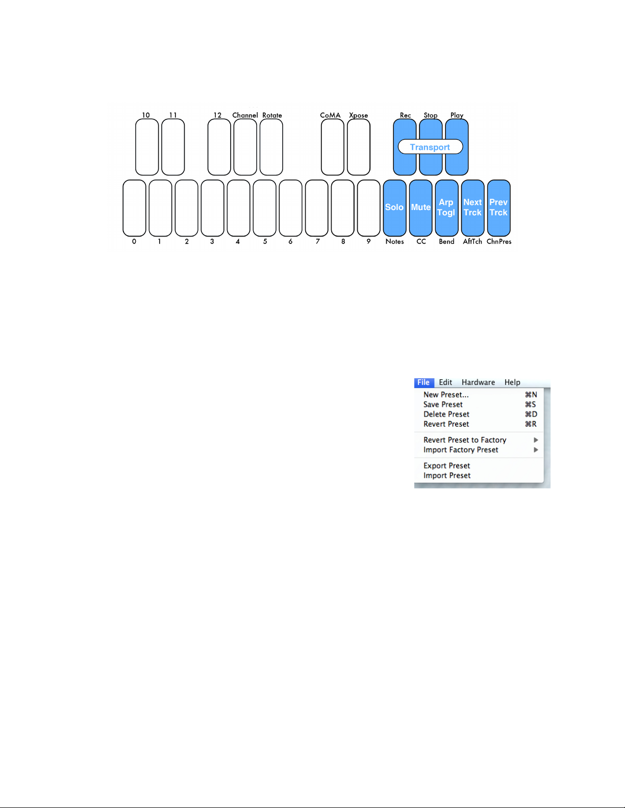
SymphonixEvolution - Symphonix Evolution is a keyboard/synth app for iPad. Use this preset
Import and Export Presets using the commands in the File Menu.
Import Preset lets you select a previously exported preset and
load it to a new slot. Export Preset will save a file containing the
currently selected preset to a location of your choice on your hard
drive for safe keeping or sharing. Importing and Exporting makes
preset sharing easy.
to extend the functionality of QuNexus with Symphonix Evolution.
The top 8 keys on QuNexus will control transport, the arpeggiator, track selection, mute, and
solo (shown in blue). The other keys (shown in white) can be used for playing melodies. These
keys also use Pressure to control modulation and tilt to control pitch bend. The Expression
Pedal controls Playback Position. For more information on using this preset with Reason, refer
to the QuNexus Symphonix Evolution Quickstart document.
Importing and Exporting Presets
7
Page 8

Menu Bar
The File menu duplicates the New, Save, Delete, and
Revert Preset functions from the Preset Library box,
assigning them shortcuts to add convenience.
You can also Revert or Import Factory Presets.
Revert Preset to Factory causes the currently preset
parameters to change to the Factory Preset selected from
the menu. The name will not change.
Import Factory Preset will create a new slot with the
original Factory Preset.
See the Importing and Exporting Presets chapter for more
information about the other File menu items.
The Edit menu contains several copy/paste functions. In
Controller Layer you can highlight a key, copy it by going to
Copy Controller Sensor, highlight another key, and paste
by going to Paste Controller Sensor.
You can also use the items within the Copy/Paste Layer
submenu to copy and paste entire layers to other Presets.
Select a Preset and use the menu options to copy its
Controller Layer, Keyboard Layer, or CV Layer. Then go to
a different Preset and paste the corresponding Layer.
The Hardware menu includes an option to force a Firmware
update. If the connected QuNexus’ firmware is already up
to date it will just re-upload the same firmware. If not the
QuNexus should automatically prompt you for an update
when you open the Editor.
Here you can also select an LED Refresh Mode for your
preset:
The QuNexus Editor’s Menu Bar contains several useful features.
Normal - LEDs behave normally, lighting up and responding to Remote LED messages as
expected.
Control Only - Only the LEDs on the Side Buttons will light up. The Keyboard LEDs will not
light when touched or respond to Remote LED Control. LEDs will still light up normally in Preset
Select and Live Edit Modes.
8
Page 9

All Off - None of the LEDs will light. The Keyboard LEDs will not respond to Remote LED
The Help menu’s Documentation will open the QuNexus
Manual.
There is also an option to Hide or Show Tool Tips. Tool Tips are
quick, helpful descriptions that pop up if the mouse hovers over
certain parameters in the Editor. Not all parameters have Tool
Tips.
Control. LEDs will still light up normally in Preset Select and Live Edit Modes.
LED Refresh Mode saves in the preset so make sure to save and send your preset to QuNexus
in order for this option to take effect. All of the Factory Presets use Normal mode.
For information about the Per Key Sensitivities option see the Per Key Sensitivities chapter.
For information about the CV Trims option see the CV Trims chapter.
For information about the Tabl es option see the View/Edit Tables chapter.
Sensitivity
There are Sensitivity controls just above the tabs. Here you can adjust the Sensitivity, On and
Off Thresholds, and the Tilt Sensitivity. These are global for the entire keyboard but can be set
differently for each preset.
Sensitivity controls how easy it is to get higher value ranges when controlling pressure and
velocity. The higher the sensitivity, the easier it will be to reach the upper range of values. The
lower the sensitivity, the more difficult or impossible it will be to get higher value ranges.
On Thresh controls the pressure value at which a note on will register. Example: If set to 10, the
Slider pressure has to reach a value of 10 before a note on is sent.
Off Thresh controls the pressure value at which a note off will register. Example: If set to 5, the
Slider pressure would have to be 5 or lower for a note off to register. This cannot be set higher
than the on threshold.
Tilt Sens. controls how easy it is to activate the Tilt source. By default, Tilt requires an
intentional pressure shift/tilt of your finger to engage. This makes it easier to activate Tilt only
when you want to. The higher the value of Tilt Sens., the easier it is to activate Tilt.
9
Page 10

Per Key Sensitivities
It is possible to adjust the sensitivities of each key individually. To do this go up to the menubar
and select Hardware and choose Per Key Sensitivities...
The above window will open. Use the sliders to make adjustments to the sensitivities of specific
keys. Move the slider up to make the key more sensitive or down to make it less sensitive.
Adjustments made here are added to the sensitivity setting in the main window. So adjustments
can be made in both places and neither will override the other.
The Reset All Keys button will return all keys to their center positions.
The settings in the Per Key Sensitivities window are not saved per preset. They are applied
globally for all presets and are sent down to QuNexus as you adjust them in real time.
10
Page 11

Keyboard Layer
Here you can choose how the QuNexus keys output MIDI. Start with what type of MIDI data you
want, go across the row, and end with the output destination (USB, Expander, or USB +
Expander). For example, if you want to add Pitch Bend to your keyboard follow these steps:
1. Find Pitch Bend in the first column.
2. Go across the row and select the desired source in the second column (like tilt).
3. Use the math modifications (Gain, Offset, Curve, Min, and Max) if you wish to, or leave
them the same if you don’t wish to alter the MIDI output values.
4. Select what MIDI output you wish to use in the final column (USB, the MIDI Expander, or
both).
The following subchapters will go into detail for each column one at a time:
Types
Note: This type is the note velocity that each key will use to output with the Note. Velocity
simulates the way a piano gets louder as the keys are struck with greater force. So the higher
the velocity values (0-127) are, the louder the MIDI notes will sound. This type is set to always
use Key Velocity as the source.
11
Page 12

Pitch Bend: Each note can bend its pitch using this type. Pitch bend is currently 7 bit. The bend
range in part depends on the MIDI device used for output but is also settable on our end using
the Bend Range box.
Channel Pressure: The Channel Pressure message is for sending a continuous pressure value
(from 0-127) for the entire keyboard (an average of the pressure of all keys on one channel).
Not all MIDI devices can interpret Channel Pressure so make sure to check the device or
software you are working with.
Poly After Touch: This is for sending a continuous pressure value (from 0-127) after a note on
for each key individually.
CCs: Stands for Continuous Controller. There are 4 rows to allow the use of 4 different CC
numbers. This MIDI format contains a controller number and a 7 bit value (0-127). It is often
used to control miscellaneous parameters like distortion amount or the volume of a mixer
channel.
Sources
Key Velocity (for notes only): The value between 0 and 127 that represents the overall
pressure on the QuNexus keys at the moment a note on (or finger on) is detected. Sensitivity
can be adjusted using the Sensitivity number box above the tabbed box.
Pressure: Continuous values (between 0 and 127) represent the applied pressure of your finger
on the QuNexus keys.
Tilt: Continuous values (between 0 and 127) represent the tilt of your finger on the QuNexus
keys. When released the value goes back to center (63). By default, Tilt requires an intentional
pressure shift/tilt of your finger to engage. This makes it easier to activate Tilt only when you
want to. You can increase the sensitivity of the tilt activation pressure by increasing the value in
the Tilt Sens. number box above the tabbed box.
Expression Pedal: When an expression pedal is plugged into the CV input of QuNexus, the
expression pedal data will be converted to MIDI and go from 0 - 127. When Channel Rotation is
enabled the Expression pedal sends out on all active Channels. If no keys are held down it will
send out on the main starting Channel.
12
Page 13

Gain, Offset, Curve, Min, and Max
After selecting your source for the MIDI data type, you can then further modify what values you
are sending to your MIDI device/software by using the math modifiers in the next five columns.
Gain: The number in the gain box is used to multiply the raw value coming from the source. For
example, setting the gain number box to “2” will double whatever value is received from the
source. Setting the gain box to 0.5 will cut the value from the source in half.
Offset: The offset is added onto the raw value after it has been multiplied by the gain value.
Curve: The result after the offset is entered into the selected curve’s lookup table and used to
plot the index on a chart. There are a number of table options, each which will affect the value
differently as it increases or decreases. The shape of each curve is pictured below:
There are two user table options that are settable from the View/Edit Tables window that you
can access from the Edit Menu. See the View/Edit Tables chapter below for more information on
setting the User Tables.
Min and Max: These allow the value to be constrained between a minimum and a maximum
number. If the min is set to 10 and the max is set to 15, then the output cannot be less than 10
or more than 15. Anything outside the range of the min and max will be truncated. Note offs will
still be at velocity 0 even if the min is set above 0.
Example: If I want Channel Pressure to control a Filter cutoff but only span half the range of the
filter I could do this two different ways:
1. Set the Channel Pressure Gain to .5 so that you only get half the values. If you wanted
to get the top half of the filter you could set the offset to 63. This would allow you to
output a pressure of 63-127 to the filter.
2. Set Min to 63 and keep Max to 127. This allows an output of 63-127.
While both methods work and set the same range of output values, the first method is probably
a better way to achieve these results. This is because the second method ignores and truncates
the first half of the pressure of your finger on the key. The first method scales the range so that
the whole range of motion is used.
13
Page 14

View/Edit Tables
The Tables window is accessible from the
Hardware Menu. When you first open it you will
see the window shown above.
You can select a table to view in the menu in the
bottom right corner. If you select “Custom 1” or
“Custom 2” the tables become editable.
When the table is editable, the line will turn
green (as shown in the image to the right). You
will be able to click the buttons along the bottom
of the window to start with one of the other
curves.
To use one of the Custom Tables, you must
make sure to select “Custom 1” or “Custom 2” in
the Curve column of Keyboard Layer or CV
Layer.
14
Page 15

Out
Set the output channels In the MIDI Channel box in the bottom left corner. There
can be separate USB and MIDI Expander Channels. If Channel Rotation is on
then the Channels set in this box act as the starting channel (see the Channel
Rotation chapter for more information).
It is also possible to change your MIDI Channel on the fly using Live Edit Mode.
See the Live Edit Mode Manual for more information.
The polyphony number sets how many channels/keys can be used at one time.
Adjust the MIDI Channel to change the starting channel.
Both the polyphony number and the MIDI Channel can be changed on the fly
using Live Edit Mode. See the Live Edit Mode Manual for more information.
The possible output destinations for the MIDI data results are:
USB: MIDI goes from the QuNexus keyboard to an attached computer through USB Port 1.
Expander: If a KMI MIDI Expander is attached, the MIDI data will go out the Expander’s 5-pin
MIDI Out port.
USB + Expander: MIDI data goes out the KMI MIDI Expander’s 5-pin MIDI Out port and to a
computer through USB port 1.
MIDI Channel
Channel Rotation
Channel Rotation is a feature that causes the order of keys pressed at one time to rotate
through channels. For example, the first pressed key’s MIDI data from Keyboard Layer goes out
Channel 1, the second pressed key’s data goes out Channel 2, the third pressed key’s data
goes out Channel 3, etc. Release those keys and you will start over on Channel 1 next time you
press a key. This feature is useful for getting a different pitch bend, channel pressure, or poly
aftertouch for each note as opposed to one for all notes.
15
Page 16

Toggl e
The Toggle box includes a menu to select between Off, On, and Legato. Below are
descriptions of each setting:
The Transpose value represents the number of semitones to transpose the
keyboard up or down.
The Transpose value can also be changed on the fly using Live Edit Mode. See
the Live Edit Mode Manual for more information.
The LED Mode box allows you to turn off Local LED Control. Local LED Control is
the QuNexus’ built-in LED behavior. Without sending LED messages to the
QuNexus from another application or device, the QuNexus’ LEDs will
automatically respond to touch.
Off - Toggle Mode will initialize as off. Pressing a key sends a note on, releasing the key sends
a note off.
On - Toggle Mode will initialize as on. Pressing a key sends a note on, a second press on the
same key turns that note off. Pressing a different key sends a note on without turning off the
previous key. Tap the Togl A button on the left side of the QuNexus to clear all notes. The LEDs
will display which keys are “on”.
Legato - Legato Mode will initialize as on. Pressing a key sends a "note on" but releasing
doesn’t send a note off. When a different key is pressed, the previous note is turned off and the
new note is turned on. Tap the Togl A button on the left side of the QuNexus to clear a note
without having to hit the next one.
Hold the Togl A button for approximately 1 second to turn Toggle (or Legato) mode on and off.
All the Factory Presets initialize with Toggle off and do not use Legato mode. If you are using a
custom preset, the Togl A button’s blue state will indicate that either Toggle or Legato is on
(depending on which your have selected in the preset).
Toggle in Keyboard Layer is separate from the toggle behavior available in Controller Layer.
See Controller Layer Toggle for more information.
Transpose
LEDs Local/Remote
There is also a number box for selecting which MIDI Channel the LEDs respond to when
sending Remote LED Control Notes to the QuNexus on USB Port 1.
16
Page 17

Remote LED Control is always allowed but if Local LED Control is enabled, the LEDs will
Here you can set the Preset to use a Program Change Message. This will
cause the QuNexus to output the Program Change value every time that
preset is selected from the QuNexus. See the Selecting Presets chapter of the
QuNexus Full Manual for more information. Program Changes can be useful
for changing presets on a synth.
Here you can set the Range of semitones for Pitch Bend. This should alter the
Min and Max setting of the Pitch Bend line above.
This selection box assigns which keys pressed will have control over the tilt,
channel pressure, poly aftertouch, and other sources of Keyboard Layer. The
options are Latest, Earliest, Highest, and Lowest. Whichever option is selected
indicates the key that will have the control. For example: if “Latest” is selected,
the last key pressed will have control over Pitch Bend if Pitch Bend is set to Tilt
(or Pressure).
prioritize the Local LED Behavior. So if you’ve sent a Remote LED Note on message to a key
and then touch and release the same key, the LED will turn off. This is because when you
released the Note the Local LED behavior turns the LED off.
See the Controlling LEDs chapter of the QuNexus Full Manual for more information about
Remote LED Control.
Program Change
Bend Range
The Bend value can also be changed on the fly using Live Edit Mode. See the Live Edit Mode
Manual for more information. The bend range is in part determined by the software or hardware
device used for output but is also set according to the Presets.
Key Priority
17
Page 18

Controller Layer
The Controller Layer tab appears next to Keyboard Layer. Here you can assign each key its
own additional Note, Toggle CC#, Pressure CC#, and Tilt CC#. Do this by clicking on any key in
the image so that it is highlighted with a green border. Then look below the image at the Sensor
Settings.
Tip: CV Layer does not convert MIDI Messages from Controller Layer.
Sensor Settings
Here you can decide what to enable for the highlighted Key. There are number boxes for
choosing which Note Numbers and CCs to use and what their behavior will be. You can choose
whether the key participates in Keyboard Layer, Controller Layer, or both. You can also set the
Channel number and the output device.
18
Page 19

Participate
Under the Pressure and Tilt CC number boxes are the Pressure CC
Return and the Tilt CC Return number boxes. These set what
values the Pressure and Tilt CC#s will return to when released. So if
the Tilt CC Return box is set to 63, when you release the key the tilt
source will go to 63. Tilt and Pressure can also latch; if the Return
boxes are set to “-1” (“latch”), then they will stay at the value when
they are released.
There are two “Participate” checkboxes on the right side of Controller Layer’s Sensor Settings,
one for Keyboard Layer and one for Controller Layer. These allow you to isolate specific keys
for controller use only, keyboard use only, or both.
If Participate in Keyboard Layer is disabled, the selected key will no longer play its regular
note or contribute to controlling Channel Pressure, Poly After Touch or anything else that might
have been set up in the Keyboard Layer tab. Local LED behavior will also turn off for that key,
meaning the keys will not light up when pressed (it can still receive Remote LED messages and
if Controller Layer Toggle is enabled, the LEDs will still show the toggle state). The Octave
buttons will no longer do anything since they only raise and lower the octave of the notes in
Keyboard Layer.
If Participate in Controller Layer is disabled, nothing you do here in Controller Layer will have
an effect on the selected key. Enabling it allows the assigned Note, Toggle CC, Pressure CC,
and Tilt CC numbers to output.
If both Keyboard Layer and Controller Layer are enabled, the selected key will send out
everything that you have assigned it here in Controller Layer Tab and also in the Keyboard
Layer Tab. For Example: if you turn Channel Pressure on and Pitch Bend set to Tilt in Keyboard
Layer and have all 4 sources on in Controller Layer, then that Key will send out 2 notes,
Channel Pressure, Pitch Bend, and CC values for an additional Pressure, Tilt, and Toggle
source. Controller Layer assignments will not increment or decrement when using the -Oct+
buttons. Neither will they Rotate Channels if Channel Rotation is enabled in Keyboard Layer.
Controller Layer Sources
Now it is established that it is necessary to enable “Participate in Controller Layer” for any keys
you wish to assign Controller Layer Notes or CC#s to. Controller Layer has 4 sources of its own
that can be assigned per key: Notes, Toggles, Pressure and Tilt. Use the Note Number, Toggle
CC, Pressure CC, and Tilt CC number boxes to set which Note number or CC number the
selected key will use for each source. Setting these number boxes to “-1” will turn the sources
off.
Specify Controller Layer’s Note Velocity with the Note Velocity Number box. Set this number
box to “-1” (“var”) to turn velocity response on and allow it to vary depending on pressure.
19
Page 20

Controller Layer Toggle
There is a dedicated CC# for Toggling in Controller Layer. This has nothing to do with the Toggle
options in Keyboard Layer. In fact, you must disable “Participate in Keyboard Layer” in order to
use the Toggle CC#. This is because Keyboard Layer has it’s own built in Toggle behavior which
cannot interact with Controller Layer’s Toggle.
With Keyboard Layer disabled, to use toggle in Controller Layer, turn the Toggle On/Off check
box on and set the Toggle CC, Toggle CC Value, and Toggle CC Return parameters.
Togg le CC - This is where you choose which CC number will toggle.
Togg le CC Va lue - This represents the CC value that will output when the Toggle state is ON.
Toggle CC Return - This represents the CC value that will output when the Toggle state is OFF.
Any Notes assigned on the same Controller Layer key with Toggle enabled will toggle with the
CC number. The Note Velocity number box will be the velocity that outputs when the Toggle
state is ON. The LEDs will indicate the toggle state.
20
Page 21

CV Layer
Here you can choose how the QuNexus keys send and receive CV (Control Voltage). QuNexus
has 4 possible CV outputs and 2 possible CV inputs (see the CV Manual for the hardware
specs).
There is a box labeled Gate S Trig in the upper right corner; if this is checked, the gate output
will be inverted so that gate on is 0V and gate off is 5V. Some older synthesizers use this
paradigm. Please consult the technical specifications of your synthesizer if you are unsure
which gate signal it needs.
The box to the left of Gate S Trig is the Gate Legato box; if this is checked, the gate output will
not iterate an off state between notes.
You can set the Pitch Scaling Scheme in the box to the left of the Gate Legato box. You can
set this to 1 Volt per Octave, 1.2 Volts per Octave, or Hertz per Volt (an older scaling scheme).
CV Output (MIDI to CV)
The MIDI to CV table has 4 rows (1 for each CV output) and 9 columns. Start with what MIDI
Device Input you are using, go across the row, and end with the CV output destination (Gate,
CV 1, CV 2, or CV 3). For example, if you want Pitch Bend Data from the MIDI Expander to go
out CV 1 follow these steps:
1. Locate the Row used for CV 1 (second row).
2. Select Expander as the MIDI Device Input.
3. Choose the MIDI Channel whose Pitch Bend data you wish to use.
21
Page 22

4. Select Pitch Bend as the MIDI Type in column 3.
The CV Trims window is accessible from the Hardware
Menu. When you click CV Trims in the menu the window
to the right will appear.
This window is provides a way to compensate for an out
of tune synthesizer by allowing you to adjust the
QuNexusʼ tuning for each pitch scaling mode. Use this
only if you are unable to adjust the tuning from the
synthesizer itself.
Increasing the Trim and offset will raise the pitch of your
synth, while decreasing the values will lower the pitch.
The settings in the CV Trims window are not saved per
preset. They are applied globally for all presets and are
sent down to QuNexus as you adjust them in real time.
5. Use the math modifications if you wish to, or leave them the same if you don’t wish to
alter the data output with math.
Tip: The Channel parameter here in CV Layer is used only for messages coming from the USB
Ports, not the keyboard itself. The CV outputs will use MIDI notes from Keyboard Layer
regardless of the Channel. Whatever the Key Priority in Keyboard Layer is set to will be the note
that CV sends out (see the Key Priority chapter for more information).
CV Input (CV to MIDI)
The CV to MIDI table has 2 rows (1 for each CV output) and 9 columns. Start with what CV
input you are using, go across the row, and end with the MIDI Device the converted MIDI Data
will be sent to (Expander, USB 3, or USB 3 + Expander). For example, if you want to convert an
Expression Pedal to control CC# 7 on Channel 1 for a device connected to the MIDI Expander
follow these steps:
1. Choose the row for CV 1 or CV 2.
2. Select the MIDI Channel to convert the CV to.
3. Select the CC # to convert the CV to.
4. Use the math modifications if you wish to, or leave them the same if you don’t wish to
alter the MIDI output with math.
5. Select which MIDI device to output the data to (MIDI Expander, USB 3, or USB 3 +
Expander).
CV Trims
22
 Loading...