

Page 1
QuNeo Reference Manual
QuNeo V0.98 BETA
May 2012
Keith McMillen, Daniel McAnulty, Conner Lacy, Jasmin Blasco, Andrew Calvo, Chuck
Carlson, Diane Douglas, Tom Ferguson, Matthew Hettich, Sarah Howe, Alex Molina, Jon
Short, Nick Wang, and Carson Whitley
1
Page 2

Copyright 2007-2011 Keith McMillen Instruments a wholly owned subsidiary of Kesumo
LLC. All rights reserved. Made in USA.
No part of this manual may be reproduced or transmitted in any form or for any purpose
without the express written permission of the copyright holders.
The content of this manual is furnished for informational use only, is subject to change
without notice, and should not be construed as a commitment by Keith McMillen
Instruments. Every effort has been made to ensure that the information in this manual
is accurate. No warranties, express or implied, are made with regard to the quality,
suitability or accuracy of this document. Keith McMillen Instruments reserves the right
to change the contents of this document and/or the associated products at any time
without the provision of prior notice to specific persons or organizations. Keith McMillen
Instruments shall not be held liable for damages of any kind arising from the use, or the
inability to use this product or its documentation, even if the possibility of such damage is
known.
Product and brand names contained in this document are used for identification purposes
only. Keith McMillen Instruments, the Keith McMillen Instruments Logo, the QuNeo and
QuNeo logo are trademarks of Kesumo LLC. Apple, Finder, GarageBand, Mac, MacBook,
Macintosh, Mac OS and QuickTime are trademarks of Apple Inc, registered in the U.S.
and other countries. Windows is a registered trademark of Microsoft Corporation in the
United States and other countries. Intel is a registered trademark of Intel Corporation
or its subsidiaries in the United States and other countries. SONiVOX is the brand name
trademark of Sonic Network, Inc. VST and ASIO are trademarks and software of Steinberg
Media Technologies GmbH. ReWire, Recycle and REX2 are trademarks of Propellerhead
Software AB. All other product and company names are trademarks or registered
trademarks of their respective holders. All other names and designations of companies,
products, trademarks, or brands used in this document are the registered property of
their respective holders.
2
Page 3
Table of Contents
Welcome
Questions or Feedback? Contact Us!
What's in the QuNeo Package
QuNeo Hardware
Connecting QuNeo
MIDI Expander
QuNeo Data Sources and Sensor Output
Source Definitions
Banks
The Mode Button
Selecting Presets
CoMA Mode
CoMA Mode Mapping Guide
Factory Preset Guides
MIDI Output
MIDI Input
QuNeo LED Behavior
Local LED Control
Remote LED Control
QuNeo Software
System Requirements
Updating the Firmware
Main Window Overview
Saving
Menu Bar
Sensor Edit Panes
Pad Edit Pane
Vertical and Horizontal Slider Edit Pane
Long Slider Edit Pane
Rotary Edit Pane
Transport Edit Pane
Left/Right Buttons Edit Pane
Up/Down Button Edit Pane
Rhombus Button Edit Pane
Sensitivity
Local LED Control
Troubleshooting
3
Page 4

Welcome
QuNeo is a 3D multi-touch pad controller. QuNeo is a different species of pad controller
for electronic musicians, DJs, VJs and DIY hackers. While it covers all of the functionality of
other pad controllers, QuNeo adds the power of touch recognition in multiple dimensions.
Each of the 27 pads, sliders and rotary sensors are pressure, velocity, and location
sensitive. The 17 buttons also respond to pressure and velocity. The 16 square pads
provide 128 levels of velocity response, X-Y location, and continuous pressure for each pad.
Each rotary sensor measures direction, pressure and location.
QuNeo is the size of an iPad and can fit in iPad accessories such as mic clips, stands and
more. QuNeo works with USB, MIDI or OSC and will communicate with your favorite music
software environments right out of the box.
In this manual you will find detailed information to help answer all of your questions about
QuNeo hardware and software.
Questions or Feedback? Contact Us!
If at any time you have any questions, please contact us:
Web: www.keithmcmillen.com
Forum: forum.keithmcmillen.com
Email: support@keithmcmillen.com
What's in the QuNeo Package
When you open up the box you should find:
● (1) QuNeo
● (1) USB A-to-Micro cable (1 meter)
● (1) QuNeo QuickStart Document
QuNeo Hardware
Dimensions: 9.5” x 7.3” x .3” (inches). The pads are about 1.2” x 1.2”.
Weight: 14 oz.
USB Port
QuNeo is connected to a computer and powered by USB. It is a class compliant USB
device and does not require a driver. This allows for maximum compatibility with an
extremely wide range of other devices.
MIDI Expander (optional)
Connect QuNeo to our KMI MIDI Expander (sold separately) to control MIDI hardware
without a computer. Power is supplied to QuNeo from the MIDI Expander’s power port.
4
Page 5
LEDs
LEDs provide the visual feedback needed for intuitive control over the QuNeo. Contained
within QuNeo are 251 LEDs with 16 different levels of brightness. The 16 square pads
provide an option of red and green on each corner, giving you 128 LEDs at your disposal
on just the pads alone. Local or Remote LED control is available. In Local, the action on
sensors will determine the LED behavior. In Remote, note or CC data input will determine
LED behavior. Local and Remote LED Control can be used simultaneously. See the
QuNeo LED Behavior chapter for more information.
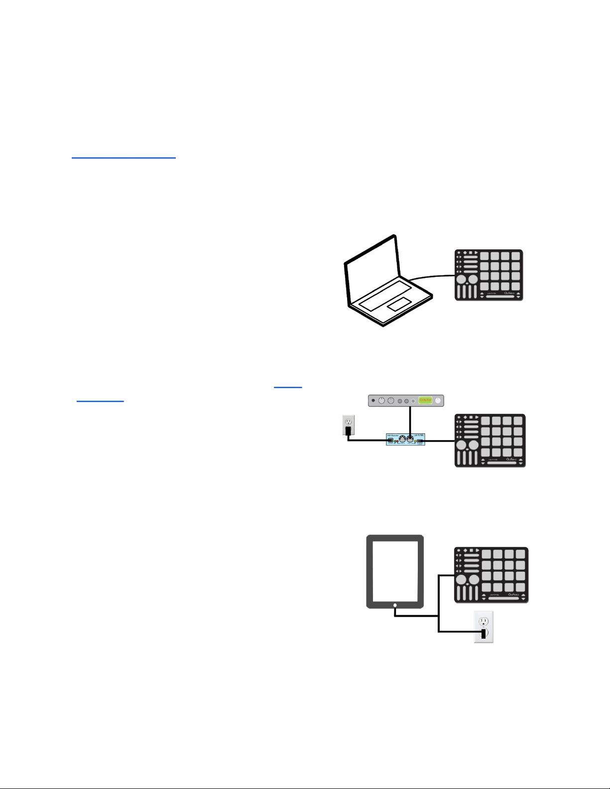
Connecting QuNeo
Connect QuNeo to a computer
This image shows QuNeo set up to send MIDI
data to a computer.
Use a USB A-to-Micro cable to connect
the QuNeo micro port to a USB port on a
computer. QuNeo will receive power from the
computer.
Connect QuNeo to MIDI hardware
The image to the right shows QuNeo
connected to a hardware synth via our MIDI
Expander (sold separately):
1. Use a USB A-to-Micro cable to connect the
QuNeo micro port to the USB “Expand” port
on the MIDI Expander.
2. Connect the power supply to the MIDI
Expander USB “Power” port.
3. Connect the MIDI Out on the Expander
to the MIDI In on a synth or other hardware
device.
Connect QuNeo to an iPad
The image to the right shows QuNeo
connected to an iPad using the QuNeo Remote
Power Kit (sold separately). This includes a Y
USB cable and a power supply. You will also
need the iPad Camera Connection Kit (sold by
Apple).
5
Page 6
MIDI Expander
The KMI MIDI Expander is an optional
accessory which enables use of
QuNeo with hardware MIDI devices.
Plug MIDI devices into the MIDI Out
port and QuNeo will send MIDI data
through a regular 5 pin MIDI cable.
Dimensions: 4” x 1.25” x 1.25”
Weight: 2.5 oz
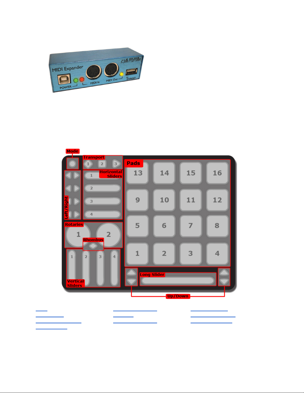
QuNeo Data Sources and Sensor Output
There are many useful types of sensors that can be found on the QuNeo:
Pads (16) Horizontal Sliders (4) Vertical Sliders (4)
Long Slider (1) Rotaries (2) Transport Buttons (3)
Left/Right Buttons (4) Up/Down Buttons (2) Rhombus Button (1)
Mode Button (1)
Each sensor type has the ability to send out multiple MIDI messages at once for several
different kinds of sources.
6
Page 7
Here is a list of exactly what kinds of sources are available in each of the sensor types:
Source Definitions
Note - Tapping on the sensor causes 1 note to output along with a velocity value relative
to how hard it is hit.
Pressure - Pressing on the sensor will cause the pressure CC# value to output from low
to high (soft to hard).
X-Axis (horizontal/side to side) - Pads only. Moving a finger from side to side across the
surface of a pad will cause the X-Axis CC# value to output going from low to high (left to
right).
Y-Axis (vertical/top to bottom) - Pads only. Moving a finger up and down across the
surface of a pad will cause the Y-Axis CC# value to output going from low to high (bottom
to top).
Tip: It is possible to set the X and Y Axis to either latch where you left it or return
to a value. When an X/Y Return value is set the X and Y Axis CC values will always
go back to that number when the pad is released. The Factory Preset Guides detail
which presets are set to latch and which use a return value.
Location - Pressing down and moving a finger along a slider or rotary will cause the
location CC# value to output going from low to high (left to right or bottom to top).
Location sources use a variation of Pass Thru Mode. Pass Thru Mode is normally when
MIDI will not be sent until you pass through the value the slider or rotary was left at.
Our Pass Thru Width parameter sets a range of pass through values. Example: If Pass
Thru Width is set to 10 and the slider was left at 40, you would have to press somewhere
between 30 and 50 to pick back up and output location data. If set to 127, you can hit
anywhere on the slider or rotary. The Factory Preset Guides detail what the Pass Thru
Width is for each preset.
Width - pressing with two fingers on the Long Slider sends a width CC# value that
represents the distance between the two fingers. The wider the gap, the higher the value.
When the second finger leaves the slider, the width will not change again until the second
finger returns to the slider.
Direction - Moving a finger around a rotary will cause the direction CC# value to output.
If finger movement is clockwise, the CC# will repetitively send out a 127. If finger
movement is counterclockwise, the CC# will repetitively send out a 0. The faster a finger
is moved, the faster the repeated value will output.
The list below will detail which sources can be used for each sensor type and how they are
implemented.
● Pads - The Pads will work differently depending on whether they are in Drum Mode
or Grid Mode. The Factory Preset Guides detail which presets use Drum or Grid
Mode and if a preset uses both on different pads.
Drum Mode - Pad sources in Drum Mode include Note, Pressure, X-Axis, and
Y-Axis.
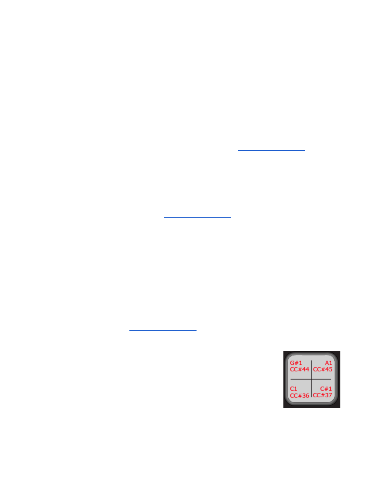
Grid Mode - While in Grid Mode, note and pressure are
available in the corner of each pad (if enabled within the
given preset). X and Y are not available in grid mode. To
the right is an example of how a Pad might be set up in Grid
Mode:
In this example each corner has a note and pressure CC#.
Hint: Throughout the QuNeo documentation note names are used to show
where notes are on and what they are set to. QuNeo treats C3 = Note #60.
In the image to the right the note numbers correspond to the pressure CC#s.
7
Page 8

● Horizontal and Vertical Sliders - If enabled in a preset, Horizontal and Vertical
Sliders use Note, Pressure, and Location. They can also be set up to have banks.
See the Banks chapter for more information.
● Long Slider - If enabled within a preset, the Long Slider uses Note, Pressure,
Location, and Width. The Long Slider can also be set up to have banks. See the
Banks chapter for more information.
● Rotaries - If enabled within a preset, the Rotaries use Note, Pressure, Location, and
Direction. Location and Direction may not be enabled simultaneously. The Rotaries
can also be set up to have banks. See the Banks chapter for more information.
● Transport Buttons - There are 3 buttons intended for transport control: the
diamond button for record, the square button for stop, and the sideways triangle for
play. If enabled within a preset, Transport Buttons use Note and Pressure.
● Left/Right and Up/Down Buttons - While bank switching is disabled, Left/Right
and Up/Down Buttons use Note and Pressure. The Left/Right and Up/Down arrow
buttons can be used either as bank switches, or as programmable MIDI buttons.
See the Banks chapter for more information.
● Rhombus Button - While bank switching is disabled, the Rhombus button uses
Note and Pressure. The Rhombus button can be used either as a bank switch, or a
programmable MIDI button. See the Banks chapter for more information.
Consult the Factory Preset Guides to determine which of the sources for each sensor are
enabled in a given preset.
Banks
Banks can be used for the sliders and rotaries if enabled. If banks are enabled for the
sliders or rotaries, a different note, pressure CC#, and location CC# can be assigned for
each bank so that each slider or rotary can control 4 different things. These banks will
be selectable using either the Left/Right Buttons, the Up/Down Buttons, or the Rhombus
Button.
The presets determine whether the sliders and rotaries have banks enabled and which
buttons are assigned as bank switches. Consult the Factory Preset Guides for this
information.
The Horizontal Slider banks are controlled individually by their neighboring Left/Right
arrow buttons. The images below show how the Horizontal Slider banks are indicated with
the Left/Right Button LEDs:
Bank 1 - no LEDs Bank 2 - left LED only Bank 3 - right LED only Bank 4 - both LEDs
In our presets, the Vertical Slider banks are all controlled using the nearest Up/Down
Button pair. The Long Slider banks are controlled using the Up/Down Button pair on
8
Page 9

the right side of the Long Slider. The images below show how the Vertical and Long Slider
banks are indicated with the Up/Down Button LEDs:
Bank 1 - no LEDs
Bank 2 - top LED only
Bank 3 - bottom LED only
Bank 4 - both LEDs
In our presets, the Rotary banks are both controlled using the Rhombus Button. The
images below show how the Rotary banks are indicated with the Rhombus Button LEDs:
Bank 1 - no LEDs Bank 2 - only the
green LED is on
Bank 3 - both red and green
are on to make orange
Bank 4 - only the
red LED is on
Using the QuNeo Editor, the bank controls for the Vertical Sliders, the Long Slider, and
the Rotaries can be chosen. Both Up/Down Button Pairs and the Rhombus Button can be
assigned to one of these sensors if editing presets in the Editor. See the QuNeo Editor
chapter for more information about editing presets.
The Mode Button
The Mode button is a small circular button that can be found in the upper left corner of the
QuNeo. When illuminated, the button is blue. The Mode button serves as the gateway to
selecting presets and entering CoMA mode (our Controller Mapping Assistant).
Selecting Presets
After plugging in the QuNeo, it will automatically load the last preset you used. The first
time, it will load Preset 1.
To enter preset mode, quickly tap the Mode button so that it begins to flash blue.
After entering Preset mode, the pad for the current
preset will be illuminated in red. Select a preset
by pressing one of the pads. The selected pad will
briefly blink green and QuNeo will exit Preset mode
and go to the selected preset.
The image to the left shows how the pads are
numbered and which pad to select for which preset
number.
Tapping the Mode button again will put QuNeo back
into Preset mode at any time.
For detailed information about the factory presets, see the Factory Preset Guides chapter of
this manual.
CoMA Mode
Many DAWs and performance software tools like Ableton Live and Apple’s Logic have MIDI
9
Page 10
Mapping modes that will recognize MIDI data from a controller and map it to whatever you
choose. Since the QuNeo can have multiple data sources for one control, it is useful to
use the Controller Mapping Assistant (CoMA). CoMA mode allows quick mapping of each
available data source one at a time, allowing for rapid and efficient software/controller
pairings.
Here is an example of how to use CoMA mode to map the Y-Axis data from a pad on
QuNeo in Ableton Live:
1. Enable MIDI Mapping mode in Ableton Live by clicking the MIDI button at the top
right-hand corner. Select the control you’d like to have QuNeo control in Live.
2. Put QuNeo into CoMA mode by holding down blue Mode button in the upper left-hand
corner for 1 second. All the LEDs will flash and the blue mode LED will turn on (and
stay on), showing that you have successfully entered CoMA mode.
3. Pick the pad you’d like to map to Live and press the bottom right (south-east) corner
of the pad. The SE corner is designated to send out the CC# for the Y-Axis.
4. Repeat step 3 for any other pads you wish to map.
5. Exit CoMA mode by pressing the Mode button again.
6. Take Live out of MIDI Map mode and try out your new mapping by pressing and
sliding your finger from top to bottom (the Y-Axis) of the pad you mapped.
CoMA Mode Mapping Guide
To enter CoMA Mode using the Mode Button, hold down on the Mode Button for 1 second
until all the LEDs flash. When in CoMA mode it is necessary to be familiar with how each
data source from QuNeo is mapped. Here is how to do this for each sensor type:
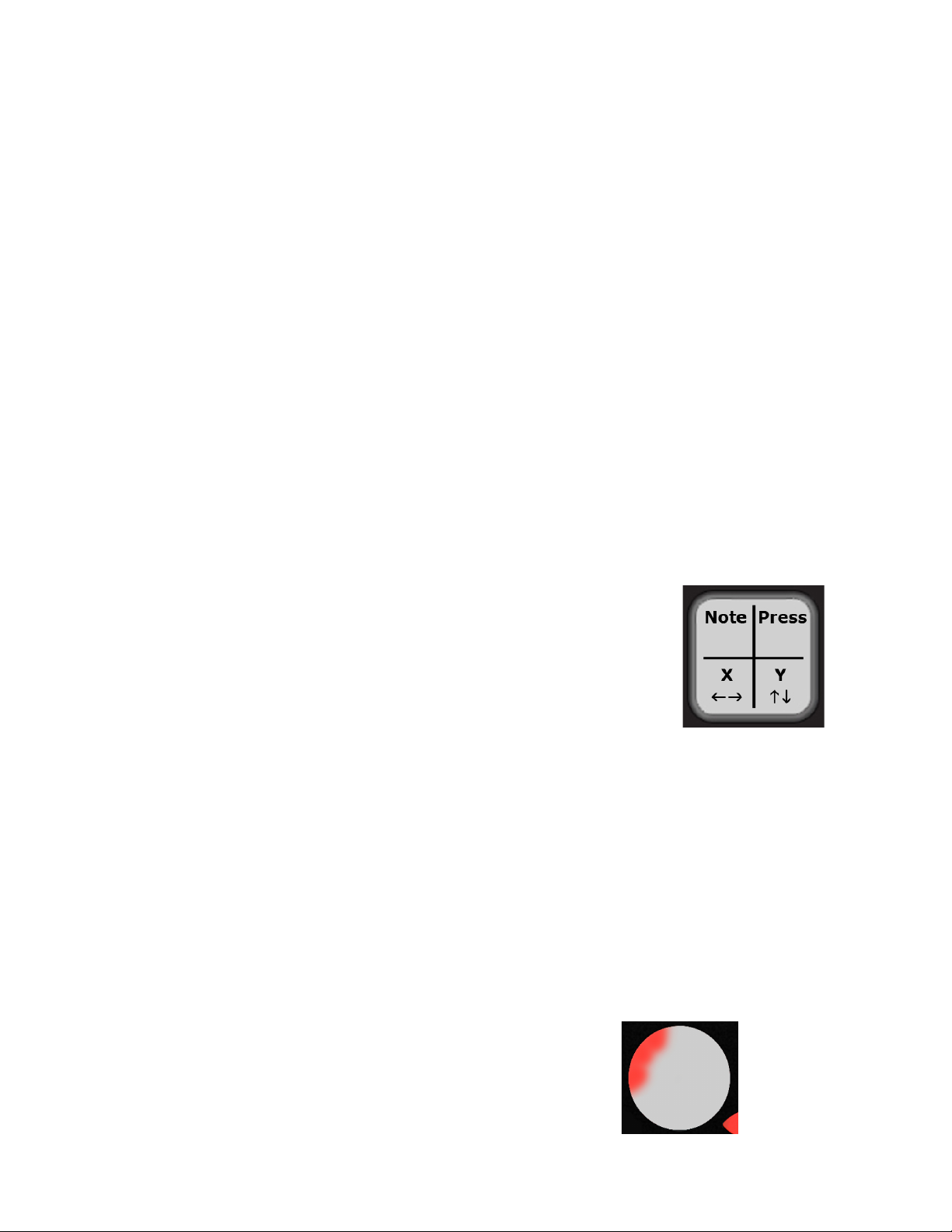
Pads -
●
When in Drum Mode each corner outputs a different
○
data source. Pressing the NW (North-West) corner
outputs the Note, the NE corner outputs the Pressure
CC#, the SW corner outputs the X-Axis CC#, and the
SE corner outputs the Y-Axis CC#.
For your convenience the red LEDs for each
■
corner will illuminate after the note or CC# is
sent out.
When Pads are in Grid Mode a Note and Pressure CC# are in each corner.
Quickly tap the corner to output the Note. Press and hold for 1 second to
output the Pressure CC#.
A red LED will illuminate for each Note sent out and a green LED will
■
illuminate for each Pressure CC#.
Sliders - to output the Note quickly tap the slider, press and hold for 1 second to
●
output the Pressure CC#, and press and drag a finger to output the Location CC#.
To output the Width CC# for the Long Slider press with 2 fingers.
The red LEDs will illuminate when the Note is sent out, the green LEDs will
illuminate for the Pressure CC#, and the yellow LEDs will illuminate for the
Location CC#. The blue LED on the Long Slider will illuminate when the Width
CC# is sent out.
Rotaries -
●
Note - Press and hold the rotary in the top
left sector.
The LEDs in the top left will illuminate
■
as soon as the note is sent out. (As
shown in image to the right).
10
Page 11
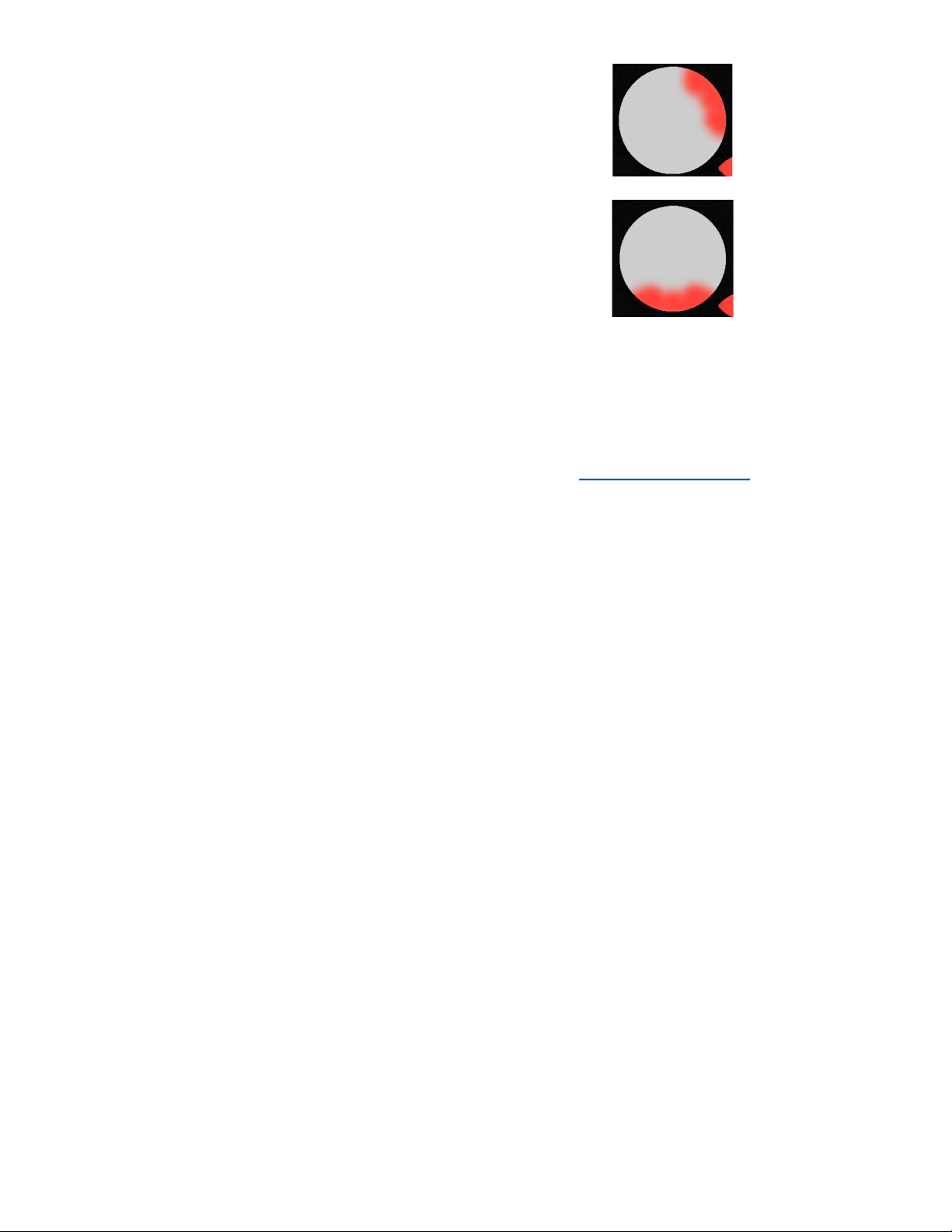
Pressure CC# - Press and hold the rotary in
the top right sector.
The LEDs in the top right will
■
illuminate. (As shown in image to
the right).
Location CC# or Direction CC# - Press and
hold the bottom sector of the rotary.
The LEDs along the bottom will
■
illuminate. (As shown in image to
the right).
Buttons - To output the Note quickly tap the button. Press and hold for 1 second
●
to output the Pressure CC#. If buttons are assigned to bank switching they will not
output their own data in CoMA mode, but instead control the banks for the Sliders
or Rotaries they are assigned to. Use the bank buttons to shift through banks, then
map the MIDI data for each of the Slider or Rotary banks.
Tip: Before using CoMA mode to map presets, consult the Factory Preset Guides to check
whether the Pads are in Grid Mode or Drum Mode for the preset you are mapping. Pad
mapping works differently for Drum and Grid mode. Also check which data sources are
enabled. There may be presets with Notes or Pressure turned off. When data sources are
turned off, they will not output in CoMA mode.
11
Page 12
Factory Preset Guides
Notes about the Preset Guide images:
● If a data source is not accounted for in the preset guide image, this means it is
disabled. For Example: If one of the Pads only shows note names and not pressure
CC#s, assume that the pressure data is turned off and will not output as MIDI data,
even in CoMA mode.
MIDI Output
Preset 1, 2, 3, & 4 (Drum Mode):
Presets 1-4 are the same except the pad notes increment up as the preset # increases. So
the pad notes on preset 1 are shown below from C1-D#2, preset 2 are from E2-G3, preset 3
are from G#3-B4, and preset 4 are from C5-D#6.
These presets are in Drum Mode and don’t use banks. Rotaries are set to use Direction
instead of Location. Pass Thru Widths for the sliders and rotaries are set to 127. The Pad
X/Y Return values are set to 63. Velocity response is enabled for all notes on the Pads;
velocity is fixed at 127 for notes on other sensors.
12
Page 13

Preset 5, 6, 7, & 8 (Grid Mode):
Presets 5-8 are the same except the Pad channels increment as the preset # increases.
These presets are in Grid Mode and don’t use banks. Rotaries are set to use Direction
instead of Location. Pass Thru Widths for the sliders and rotaries are set to 127. Velocity
response is fixed at 127 for all notes.
Presets 9 & 10 (Ableton Live):
Descriptions coming soon!
13
Page 14

Preset 11 (Traktor - DJ):
The Traktor DJ Preset turns QuNeo into a full fledged DJ controller for Native Instruments'
Traktor. This preset is designed with a more traditional approach to digital DJing in
mind, with play, sync, cue, monitor, fx, filter, loop points, cue points, crossfading, deck
control, and various volume controls accessible from QuNeo. In addition, this preset takes
advantage of the modifier functions, creating a Shift button on QuNeo that allows for
sample playback, extended mixing, and more in depth FX control.
The image below shows what each sensor controls in our Traktor DJ Template (included in
the QuNeo Software Installer):
14
Page 15

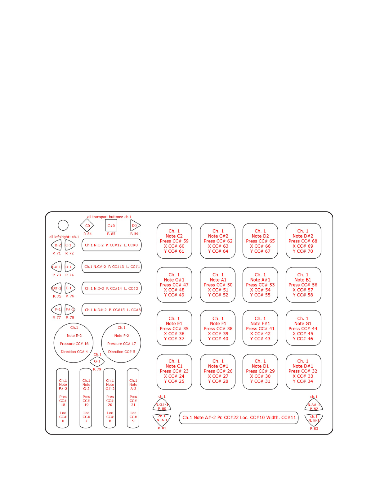
This image shows what MIDI data will output for each sensor in the “Traktor - DJ” preset.
The top 2 rows of Pads are in Grid Mode and the bottom 2 rows of Pads are in Drum Mode.
This preset doesn’t use banks. Rotaries are set to use Direction instead of Location. Pass
Thru Widths for the sliders and rotaries are set to 127. The bottom 2 rows of Pads’ X/Y
Return values are set to 63. Velocity response is fixed at 127 for all notes.
15
Page 16

Preset 12 (Traktor - FX):
The Traktor FX preset turns QuNeo into an effects controller for Native Instruments' Traktor.
The Pads are evenly split to control Deck A on the left and Deck B on the right. Each
column is assigned to an FX unit. Each row controls the amount of each effect slot within
that FX unit. The bottom row controls the dry/wet for each FX unit. When a finger is on a
pad, the effect turns on and the pressure controls the amount of the effect. When a finger
lifts off the pad, the effect turns off. When pressed, the QuNeo's green play button enables
the top row of pads to control a second effect.
The image below shows what each sensor controls in our Traktor FX Template (included in
the QuNeo Software Installer):
16
Page 17

This image shows what MIDI data will output for each sensor in the “Traktor - FX” preset.
This preset uses Drum Mode. Banks are not enabled. Rotaries are set to use Direction
instead of Location. Pass Thru Widths for the sliders and rotaries are set to 127. X/Y
sources on the Pads are set to latch. Velocity response is fixed at 127 for all notes.
17
Page 18

Preset 13 (Reason):
Description coming soon!
Preset 14 (Battery):
This preset is for use with Native Instrument’s Battery 3. Each pad in the left 2 columns
outputs 1 note to trigger 1 cell in the first 2 columns in Battery. If you hold that pad down
and tilt your finger left and right, or up and down you control the filter frequency and filter
resonance on that sample. These settings will stay where you leave them when you take
your finger off.
Each pad in the right 2 columns of QuNeo outputs a note on each corner to trigger 1 cell
in each of the 8 columns in the middle. This way you can have 4 different high hat sounds
layered on one pad, each of which is sensitive to velocity. Each of the rotaries triggers all
4 cells in the last two columns in Battery on the right. There is one loop on each rotary.
Pressure controls a filter cutoff frequency on each rotary's loop, and turning the rotary up
shortens the loop length.
The image below shows what each sensor controls in our Battery Template (included in the
QuNeo Software Installer):
18
Page 19

This image shows what MIDI data will output for each sensor in the “Battery” preset. In
this preset the Pads use Drum Mode in the left 2 columns and grid mode in the right 2
columns. Banks are not enabled. Rotaries are set to use Location instead of Direction.
Pass Thru Widths for the sliders and rotaries are set to 127. X/Y sources on the Pads are
set to latch. Velocity response is enabled for notes on Pads and Rotaries. Velocity is fixed
at 127 for notes on buttons and sliders.
Presets 15 & 16 (User 1/User 2):
These presets start out blank so users can start a new preset from scratch.
19
Page 20

MIDI Input
Use the MIDI Input guides below to find out what MIDI data to send the QuNeo to
control the LEDs remotely. See the Remote LED Control chapter of this manual for more
information.
Drum Mode:
It is also possible to use 1 note per pad. In this
case the velocity of the note will fade the LEDs
from green to red. Send the notes in the image
to the right to QuNeo on Channel 3.
20
Page 21

Grid Mode:
21
Page 22

QuNeo LED Behavior
QuNeo’s LEDs provide many great ways to visualize interactions with the QuNeo. Local or
Remote control is available. Local LED Control means the action on sensors will determine
the LED behavior. Remote LED Control means note or CC Data being sent to the QuNeo
will determine LED behavior. Local and Remote control can be used simultaneously as well.
Local LED Control
Without sending LED messages to the QuNeo from another application or device, the
QuNeo’s LEDs will automatically respond to touch. Local LED Control is the QuNeo’s built-in
LED behavior and will override any currently incoming Remote messages. Here is how the
LEDs will behave for each sensor.
● Pad LEDs - The LEDs in each corner of the pad will illuminate individually with color
and brightness corresponding to velocity and pressure (from green to red). If the
Pads are in Drum mode and the X/Y Axis sources are set to latch, the LEDs will latch
too.
● Horizontal and Vertical Slider LEDs - The LEDs will illuminate to where a finger is
and fill in from the left (for Horizontal) or bottom (for Vertical).
● Long Slider LEDs - The LEDs will illuminate where a finger is. If a second finger
touches the slider, then the LEDs will illuminate between the two fingers.
● Rotary LEDs - When the rotary is pressed, all LEDs will illuminate around the finger.
When released, one LED will show where the finger last was.
● Transport Button LEDs - When the button is pressed, the LED will illuminate.
When released, the LED will turn off.
● Left/Right Button LEDs
When Bank Switching is off - When the button is pressed, the LED will
illuminate. When released, the LED will turn off.
When Bank Switching is enabled - LED of the Left/Right arrow pairs indicate
the banks that the corresponding Horizontal Slider is in.
Bank 1 - no LEDs Bank 2 - left LED only
Bank 3 - right LED only Bank 4 - both LEDs
22
Page 23

● Up/Down Button LEDs
When Bank Switching is off - When the button is pressed, the LED will
illuminate. When released, the LED will turn off.
When Bank Switching is enabled - The LEDs for the two buttons will indicate
which bank the corresponding sensors are in.
Bank 1 - no LEDs
Bank 2 - top LED only Bank 3 - bottom LED only Bank 4 - both LEDs
● Rhombus Button LEDs
When Bank Switching is off - When the button is pressed, both the red and
green LEDs will illuminate. When released, the LEDs will turn off.
When Bank Switching is enabled - The LEDs for the button will indicate which
bank the corresponding sensors are in.
Bank 1 - no LEDs
Bank 2 - only the
green LED is on
● Mode Button LEDs
When tapped to go into Preset mode, the Mode Button’s blue LED will blink
When held for 1 second to go into CoMA mode, the Mode Button’s blue LED
will illuminate
Remote LED Control
Bank 3 - both red and green
are on to make orange
Bank 4 - only the
red LED is on
The LEDs on the QuNeo can be sent MIDI messages to control their behavior. When the
QuNeo receives the proper MIDI data for a pad, slider, button, etc., the LEDs will respond
accordingly. If you are touching the QuNeo, the Local LED control will momentarily override
the Remote LED Control for as long as a finger is pressed down. When released, Remote
LED Control will take over again. You can disable Local LED control using the editor.
To learn what MIDI messages can be sent to the LEDs, consult the MIDI Input chapter of
the Factory Presets Guide.
Here is a list of the possible ways to control the LEDs when using Remote LED Control:
● Pad LEDs
When in Drum Mode - Pads can receive a note for the green LEDs and a note
for the red LEDs. The velocity of the note will determine the brightness.
It is also possible to use 1 note per pad. In this case the velocity of
the note will fade the LEDs from green to red.
When in Grid Mode - The LEDs in each corner of the pad can light up
individually. Pads can receive 4 notes (one for each corner) for the green
LEDs and 4 other notes for the red LEDs. The velocity of the note will
determine the brightness.
23
Page 24

● Horizontal and Vertical Slider LEDs - Each slider can receive a CC# value for
LED location. This will tell the slider where the LEDs should fill up to. They will fill
in from the left (for Horizontal) or bottom (for Vertical). This works great for VU
meters.
● Long Slider LEDs - The Long Slider can receive a CC# value for LED location. This
will tell the slider which of the LEDs should light up.
● Rotary LEDs - Each rotary can receive a CC# value for LED location. This will tell
the slider which of the LEDs should light up.
● Transport Button LEDs - Each Transport button can receive a note for its LED. A
note with velocity above 0 will turn the LED on and the velocity of the note will also
determine the brightness.
● Left/Right Button LEDs
When Bank Switching is off - Each of the arrow buttons will respond to a note.
A note with velocity above 0 will illuminate the LED and the velocity of the
note will determine the brightness.
When Bank Switching is enabled - The LEDs will not respond to remote
messages. Instead they will behave the way they do in Local LED Control.
● Up/Down Button LEDs
When Bank Switching is off - Each of the arrow buttons will respond to a note.
A note with velocity above 0 will illuminate the LED and the velocity of the
note will determine the brightness.
When Bank Switching is enabled - The LEDs will not respond to remote
messages. Instead they will behave the way they do in Local LED Control.
● Rhombus Button LEDs
When Bank Switching is off - The Rhombus button can receive a note for
the red LED and a note for the green LED. A note with velocity above 0 will
illuminate the LED and the velocity of the note will determine the brightness.
When Bank Switching is on - The LEDs will not respond to remote messages.
Instead they will behave the way they do in Local LED Control.
● Mode Button LEDs - The Mode button will not respond to remote messages.
Instead it will behave the way it does in Local LED Control.
24
Page 25

QuNeo Software
Download our free QuNeo Software Installer from: http://www.keithmcmillen.com/QuNeo/
downloads/
The Software Installer contains template files that go with QuNeo presets for Ableton Live,
Traktor, Battery, and Reason. All of these can be automatically copied onto a computer by
running the QuNeo Software Installer.
Installation Instructions (Mac)
Unzip the file after downloading and double-click on the .dmg file to open the disk image,
then double-click on the QuNeo Software Installer.
On the “Installation Type” page, select
the software you want to use with QuNeo
(as shown in the image to the right). Hit
continue, enter your admin password, and
the installer will copy over any necessary
auto-mapping files. A QuNeo folder will now
appear in the Applications directory on your
computer.
Installation Instructions (Windows)
Unzip the file after downloading and double-click
on the .exe file to launch the QuNeo Software
Installer. This will copy all of the necessary
files and documentation into the Program Files
directory. A different directory may be selected
if desired. Click the “Unzip” button as shown
in the image to the right. When installation is
complete click the close button.
Now that the software is installed, look inside the QuNeo folder to find a “Documentation”
folder, a “Software_Examples” folder, and a “QuNeo_Editor” folder. Template files for the
software you selected will appear in the “Software_Examples” folder. To use them just plug
in QuNeo, select the corresponding preset, and try out the example. Use the Factory Preset
Guides in this manual for more information about the presets for these examples.
The “QuNeo_Editor” folder will contain the QuNeo Editor. Use this to make changes to
QuNeo’s presets. Once installed keep everything in the “QuNeo_Editor” folder as is so
the application can access everything it needs to run.
25
Page 26

System Requirements
We recommend the following minimum system requirements for the QuNeo Editor and the
Software Examples:
MAC:
● An Intel Core 2 Duo 2.3GHz or greater
● Mac OS 10.5 or later
WINDOWS:
Windows XP, or Windows 7
●
Intel Core 2 processor or greater
●
1GB of RAM with 50 MB free hard disk space
●
Updating the Firmware
Make sure the editor and the firmware versions are compatible with each other.
When the QuNeo Editor opens, it checks to make
sure the firmware on the device is compatible
with the application. If the firmware is not
compatible, an update prompt will appear. Click
ok and wait until the blue Mode button light
stops flashing and the “Update Complete” dialog
appears before continuing. The blue light and
progress bar on screen indicate that the firmware
update is in progress.
An “Update Firmware” option is located in the
file menu of the QuNeo Editor. Select this option
and the prompt to the right will appear. Click ok
to update firmware.
Keith McMillen Instruments cannot be held liable for damage resulting from
installation and operation errors or improper use.
26
Page 27
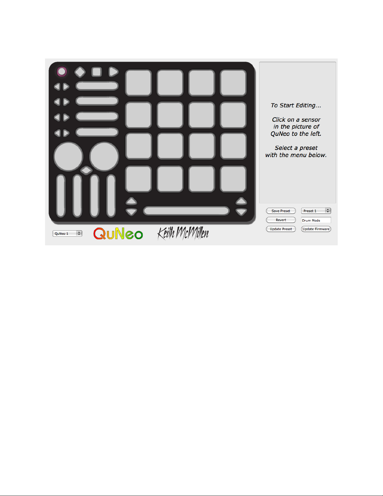
Main Window Overview
The QuNeo Editor opens with this window:
Selecting a sensor on the QuNeo image will open an edit pane in the box to the right. In
the edit pane, one can adjust the settings and MIDI data for the selected sensor.
In the bottom left side of the window is an indicator to show that QuNeo is connected to the
Editor. If the Editor has found the QuNeo, the device indicator will automatically change
to “QuNeo 1” (after the application fully loads) to show that a connection between the Editor
and QuNeo has been made.
Controls for saving and recalling presets are found in the bottom right side of the window.
27
Page 28

Saving
Select presets from the menu, name them in the text
box, and save or revert them with the “Save Preset”
and “Revert” buttons. Press the “Update Preset”
button to send the current preset to the QuNeo or
press the “Update All” button to send all of the
presets to the QuNeo.
If edits are made to the selected preset, the Save
Preset button will begin to blink red as a reminder
to save. Click the save button to save the selected
preset, and it will cease to blink red. Modified/unsaved
presets will appear in the preset list with an asterisk
until they are saved.
Click the Revert button to go back to the previously
saved state of the current preset.
In the menu, the presets are listed by number to correspond with the pad numbering when
selecting presets from the QuNeo (see the Selecting Presets chapter for more information).
Menu Bar
More functions can be accessed from the File menu.
“Export Presets” will save a file containing the
currently selected preset for safe keeping or sharing.
“Import Presets” opens previously exported presets
into the currently selected preset slot. Importing and
Exporting makes preset sharing easy.
“Revert to Factory Presets” reloads the original presets into the editor. After reverting to
the factory presets, save each preset to keep the factory versions.
The “Update Firmware” option will open up a firmware update prompt. Click ok and the
firmware will update. (see the “Updating the Firmware” chapter of this manual for more
information).
The Edit menu contains copy and paste functions.
“Copy Current Preset” will put the current
preset onto the application’s clipboard. To
paste a copied preset into a different preset, use
the “Paste to Current Preset” option. It will
then be necessary to save the pasted preset.
“Copy Sensor” places parameters from the current sensor’s edit pane on the clipboard.
Selecting another sensor of the same type enables the “Paste Sensor” option. “Edit Next
Sensor” opens the next sensor’s edit pane.
28
Page 29

Sensor Edit Panes
The image above shows Pad 13 selected on the QuNeo image and the Pad 13 edit pane
open on the right side of the window. Pad 13 is highlighted pink to show that it is selected.
When editing a parameter in the edit pane, the parameter is displayed on the QuNeo image;
as are the similar parameters for all sensors.
Example: In the image below, the Note parameter for Pad 13 is set to MIDI note 60 (C3).
All of the other pads will display their notes as well. This allows easy checking to prevent
unwanted duplicate notes.
Adjusting the Pressure parameter changes the QuNeo image to display what CC# is
assigned to pressure on all of the pads.
All parameters are displayed in this way for all sensor types.
Read on for more detail about the editable parameters in each of the various edit panes.
29
Page 30

Pad Edit Pane
The Pads function in either Drum Mode or Grid
Mode. In Drum Mode, it is not possible to edit the
parameters for Grid Mode and vice-versa. Enter Grid
Mode by clicking on the “Grid Mode” check box.
In Drum Mode, the pad parameters include a note,
pressure CC#, X-Axis position CC#, Y-Axis position
CC#, and an X/Y Return value.
In Grid Mode, the pad sources include note and
pressure in each corner, allowing up to 4 notes or
pressure points per pad.
To disable a source, set the number box below 0
to “off”. Enable velocity sensitivity for MIDI notes with
the “Vel” check boxes. If unchecked the velocity of
the note (if the note is enabled) will be fixed at 127.
X/Y Return is the value that X and Y CC#s will return
to when the Pad is released. If the number box is set
below 0 the values will “latch”, staying where they
were left when the pad was released.
The image to the left displays the parameters for Grid
Mode. It is divided to show which of these parameters
correspond to each corner of the pad. The parameters
of each pad corner contain a note, velocity switch, and
pressure CC#. The placement of the parameters in
the edit pane corresponds to the corners of the pads.
Sensitivity and Local LED Control parameters are at the very bottom of the edit pane. For
more information on these please reference the Sensitivity and Local LED Control chapters
in this section of the manual.
30
Page 31

Vertical and Horizontal Slider Edit Pane
The Vertical and Horizontal Slider Edit Panes have
essentially the same editable parameters.
There are 4 banks available per slider.
The Horizontal Sliders each have their own Left/Right
Buttons to control which bank is selected. (See the Left/
Right Buttons Edit Pane chapter for more information).
The banks of the Vertical Sliders can be selected by using
either the Rhombus button, or one of the Up/Down button
pairs. This is programmable in the edit panes for those
buttons. (See the Rhombus Button Edit Pane or the Up/
Down Buttons Edit Pane chapters for more information).
The Slider Edit Pane parameters include a Note, Pressure
CC#, Location CC#, and Pass Thru Width for each bank.
The sliders use a variation of Pass Thru Mode. Normally,
in pass through mode, MIDI will not be sent until the value
the slider was left at is triggered. Pass Thru Width sets
a range of pass through values. Example: If Pass Thru
Width is set to 10 and the slider was left at 40, it would be
necessary to press somewhere between 30 and 50 to pick
back up and output location data. If set to 127, the whole
range of the slider will respond.
To disable a source, set the number box below 0 to “off”. Enable velocity sensitivity for
MIDI notes with the “Vel” check boxes. If unchecked the velocity of the note (if the note is
enabled) will be fixed at 127.
Sensitivity and Local LED Control parameters are at the very bottom of the edit pane. For
more information on these please reference the Sensitivity and Local LED Control chapters
in this section of the manual.
31
Page 32

Long Slider Edit Pane
The Long Slider Edit Pane is similar to the Vertical and
Horizontal Slider edit panes.
There are 4 banks available. The banks of the Long
Slider can be selected by using either the Rhombus
button, or one of the Up/Down button pairs. This is
programmable in the edit panes for those buttons.
(See the Rhombus Button Edit Pane or the Up/Down
Buttons Edit Pane chapters for more information).
The Long Slider Edit Pane parameters include a Note,
Pressure CC#, Location CC#, Width CC#, and Pass
Thru Width for each bank.
The Long Slider use a variation of Pass Thru Mode.
Normally, in pass through mode, MIDI will not be sent
until the value the slider was left at is triggered. Pass
Thru Width sets a range of pass through values.
Example: If Pass Thru Width is set to 10 and the
slider was left at 40, it would be necessary to press
somewhere between 30 and 50 to pick back up and
output location data. If set to 127, the whole range of
the slider will respond.
To disable a source, set the number box below 0 to “off”. Enable velocity sensitivity for
MIDI notes with the “Vel” check boxes. If unchecked the velocity of the note (if the note is
enabled) will be fixed at 127.
The Sensitivity and Local LED Control parameters are at the very bottom of the edit pane.
For more information on these please reference the Sensitivity and Local LED Control
chapters in this section of the manual.
32
Page 33

Rotary Edit Pane
The Rotary Edit Panes are also similar to the Slider
Edit Panes.
There are 4 banks available per slider. The banks of
the Rotaries can be selected by either the Rhombus
button, or one of the Up/Down button pairs. This is
programmable in the edit panes for those buttons.
(See the Rhombus Button Edit Pane or the Up/Down
Buttons Edit Pane chapters for more information).
The Rotary Edit Pane parameters include a Note,
Pressure CC#, Location CC#, Pass Thru Width,
Direction CC#, and Speed for each bank.
The Direction CC# will repetitively send out a 127 if
finger movement is clockwise. If finger movement is
counterclockwise, the CC# will repetitively send out
a 0. We refer to this repetitive CC# as a tick. The
faster a finger is moved, the faster the tick will output.
The Speed parameter controls the number of ticks per
degree.
Direction and Location cannot be used at the same
time.
The Rotaries use a variation of Pass Thru Mode. Normally, in pass through mode, MIDI
will not be sent until the value the rotary was left at is triggered. Pass Thru Width sets
a range of pass through values. Example: If Pass Thru Width is set to 10 and the rotary
was left at 40, it would be necessary to press somewhere between 30 and 50 to pick back
up and output location data. If set to 127, the whole range of the rotary will respond.
To disable a source, set the number box below 0 to “off”. Enable velocity sensitivity for
MIDI notes with the “Vel” check boxes. If unchecked the velocity of the note (if the note is
enabled) will be fixed at 127.
The Sensitivity and Local LED Control parameters are at the very bottom of the edit pane.
For more information on these please reference the Sensitivity and Local LED Control
chapters in this section of the manual.
33
Page 34

Transport Edit Pane
The Transport buttons are the 3 buttons at the top of the
QuNeo next to the Mode button. The diamond button
with the red LED is the record button, the square button
with the yellow LED is the stop button, and the triangular
button with the green LED is the play button. Assign
the Channel, Note, and Pressure CC# for each Transport
button.
To disable a source, set the number box below 0 to “off”.
Enable velocity sensitivity for MIDI notes with the “Vel”
check boxes. If unchecked the velocity of the note (if the
note is enabled) will be fixed at 127.
The Sensitivity and Local LED Control parameters are at
the very bottom of the edit pane. For more information
on these please reference the Sensitivity and Local LED
Control chapters in this section of the manual.
Left/Right Buttons Edit Pane
The Left/Right buttons are positioned to the left of each
Horizontal slider. If the “Enable Bank Switching” box
is checked, these button pairs act as bank controls for
each Horizontal Slider. See the Vertical and Horizontal
Slider Edit Pane chapter for more info. The banks will be
indicated by the LEDs of the 2 buttons.
For information about how the LEDs indicate the banks,
see the Left/Right Buttons and Banks chapter of this
manual.
If Bank Switching is disabled, each button can output an
assigned Note or Pressure CC#.
To disable a source, set the number box below 0 to “off”.
Enable velocity sensitivity for MIDI notes with the “Vel”
check boxes. If unchecked the velocity of the note (if the
note is enabled) will be fixed at 127.
The Sensitivity and Local LED Control parameters are at the very bottom of the edit pane.
For more information on these please reference the Sensitivity and Local LED Control
chapters in this section of the manual.
34
Page 35

Up/Down Button Edit Pane
The Up/Down buttons are positioned on either side of
the Long Slider. If the “Enable Bank Switching” box is
checked, these button pairs act as bank controls for the
Rotaries, Vertical Sliders, or Long Slider. See the Vertical
and Horizontal Slider Edit Pane, Long Slider Edit Pane, or
Rotary Edit Pane chapters for more info. The banks will be
indicated by the LEDs of the 2 buttons.
For information about how the LEDs indicate the banks,
see the Up/Down Buttons and Banks chapter of this
manual.
If Bank Switching is disabled, each button can output an
assigned Note or Pressure CC#.
To disable a source, set the number box below 0 to “off”.
Enable velocity sensitivity for MIDI notes with the “Vel”
check boxes. If unchecked the velocity of the note (if the
note is enabled) will be fixed at 127.
The Sensitivity and Local LED Control parameters are at the very bottom of the edit pane.
For more information on these please reference the Sensitivity and Local LED Control
chapters in this section of the manual.
Rhombus Button Edit Pane
The Rhombus button is positioned under the Rotaries
and above the Vertical Sliders. If the “Enable Bank
Switching” box is checked, this button acts as a bank
control for the Rotaries, Vertical Sliders, or Long Slider.
See the Vertical and Horizontal Slider Edit Pane, Long
Slider Edit Pane, or Rotary Edit Pane chapters for more
info. The banks will be indicated by the LEDs of the
button.
For information about how the LEDs indicate the banks,
see the Rhombus Button and Banks chapter of this
manual.
If Bank Switching is disabled, the button can output an
assigned Note or Pressure CC#.
To disable a source, set the number box below 0 to “off”.
Enable velocity sensitivity for the MIDI note with the “Vel”
check boxes. If unchecked the velocity of the note (if the
note is enabled) will be fixed at 127.
The Sensitivity and Local LED Control parameters are at the very bottom of the edit pane.
For more information on these please reference the Sensitivity and Local LED Control
chapters in this section of the manual.
35
Page 36

Sensitivity
Sensitivity is editable for the various sensors using the sensitivity dial at the bottom of
each of the edit panes. This will adjust the on threshold for the sensor. If the sensitivity
knob is all the way up, the on threshold will be lower, allowing less pressure before
registering any activity. If the sensitivity is all the way down, the on threshold will be
higher, requiring more pressure before registering any activity.
The Sensitivity dial is global for all controls of that type.
Example: Adjusting the sensitivity in one of the Pad Edit Panes will adjust the sensitivity
for all pad edit panes. The Sensitivity dials for the Horizontal Sliders are linked, the Vertical
Sliders, the Left/Right Buttons, etc...
Local LED Control
In each Edit Pane, next to the Sensitivity dial, is a check box for turning Local LED Control
on and off. Without sending LED messages to the QuNeo from another application or
device, the QuNeo’s LEDs will automatically respond to touch. This built-in LED behavior
can be enabled using the Local LED Control check box. Like the sensitivity dial, the Local
LED Control check box is global for all controls of that type.
Hint: If Local LED Control is disabled and the QuNeo is not receiving MIDI notes for
controlling LEDs, the QuNeo will not light up at all.
In the Left/Right, Up/Down, and Rhombus Button edit panes, if Bank Switching is enabled,
Local LED Control cannot be disabled.
36
Page 37

Troubleshooting
Coming Soon!
If you experience any problems or have questions regarding the QuNeo install process email us at support@keithmcmillen.com outlining the problems you're experiencing. The
more detailed you are in describing your problem (information about your computer, the
software you're running, the circumstances around the issue), the more easily we will be
able to help you.
37
 Loading...