

Page 1
SPECIFICATIONS
VOLTS TEMPERATURE
MAXIMUM t YR.. 23’ *ST &WC a 2860°C
RANGE
2Oh” 199.999XlO~ 0.01 %f25 0.00*%+30
2: z
200 v 199.999 0.02% + 10 0.002%+ 0.3
INPUT CAPACITANCE: Less than or equal to 2OpF. INPUT CAPACITANCE: Less than or equal to 2OpF.
INPUT RESISTANCE: Greater than or equal to 2OTi,. INPUT RESISTANCE: Greater than or equal to 2OTi,.
NMRR: Greater than 55dS (greater than SWS with FILTER). NMRR: Greater than 55dS (greater than SWS with FILTER).
CMRR: Greater than 1OOdS (greater than l25dS with FILTER). CMRR: Greater than 1OOdS (greater than l25dS with FILTER).
ANALOG SETTLING TIME ItoO.l% of final value, unfiltered): Lessthan ANALOG SETTLING TIME ItoO.l% of final value, unfiltered): Lessthan
5ms. 5ms.
REAOINQ * I%rdg + OO”“ts, * wrdg + EO”“b,,~C
1.99999 0.01 x7+,0 0.002%+ 3
19,999s 0.02% + 10 o.oo*%+ 0.3
AMPS AMPS
f.lAxlM”M 1 VR.. 23-*vc f.lAxlM”M 1 VR.. 23-*vc 019% * 2.a.wc 019% * 2.a.wc ANALOG ANALOG
RANOE READINO *,%rdg+co”“ts, *,%rdg+oO”“ts,,~C RANOE READINO *,%rdg+co”“ts, *,%rdg+oO”“ts,,~C
2 “A 1.99999x 10Q 2 “A 1.99999x 10Q 0.35% +a 0.35% +a
20 nA 19.9999x
20 nA 19.9999x
200 nPi 100.999 x lcr9 200 nPi 100.999 x lcr9 0.15% +26 0.15% +26 O.O1%C30 O.O1%C30
2 &A 1.99999x10-~ 2 &A 1.99999x10-~
20 +A 19.9999 x 10⁶ 20 +A 19.9999 x 10⁶
200 PA 199.999 x 10⁸ 200 “A 199.999 x 10⁸
2nlA 1.99999x lo-3
2nlA 1.99999x lo-3
20rnA 19.9999 x 10~3 0.15% + to cm,%+ 3
20rnA 19.9999 x 10~3 0.15% + to cm,%+ 3
INPUT VOLTAGE DROP: Less than ImV st full-scale except less than 0.6”
ANALOG SETTLING TIME Ito 0.1% of final value, unfllteredl: 2nA
NMRR: 2nA through 2+&n: 70dS; ZO,,A through ZA: 5EdS.
1.99999 0.15%125 0.01%+20
1.99999 0.15%125 0.01%+20
2A
2A
on 2A range.
through 2pA: 50ms; 20+A through 2A: 5ms.
OHMS TEMPERATwtE
MAXlMUM
RANOE READlNG
2 k0 1.99999x10³
20 k0 19.9999x10³
200 k” 199.999x101
aA* 1.99999 x 106
*ml* 19.9999x10⁶
200M” 199.999x10⁵
2 GO 1.99999x 10⁹
20 0” 19.9999x10⁹
200 GO 199.999x10⁹
2 m 1.99999 x 10’2
OHMS CURRENT SOURCES: 2k0. 20kk ,OO&
ANALOG OUTPUT: Analog output voltage level is ths product of ths Ohms
current source and the resistance being measured.
ANALOG SE’ITLING TIMES:
To 0.1% of final value, unfiltered, with
less than lOOpF input cspacitsnce: 20Mn: 20ms.
To 10% of final value, unfiltered,
using 6191 Guarded Input Adapter
with less than IpF unguarded input ZOOGD: 15s
cap.acitance:
ACCURACY ACCURACY COEFFICIENT COEFFICIENT FULL SCALE FULL SCALE
lo-9
lo-9
ACCVRAC”
1 YR.. 23~*5%
* I%dc! + Cc.““uL,
ACCVRACV COEFFIUENT
TEMPERATURE TEMPERATURE
lN”ERTlNO lN”ERTlNO
0”TP”T 0”TP”T
0.02% + 30 0.02% + 30 0.2v 0.2v
0.35% +35 0.35% +35
0.15?6+,0 0.15?6+,0 o.ol%+ 3 o.ol%+ 3 2.0” 2.0”
0.15%+25 0.15%+25 ml%+30 ml%+30 0.2” 0.2”
0.15% + 10 0.15% + 10 o.ot%+ 3 o.ot%+ 3 2.0” 2.0”
0.1536+25 0.0,%+30
0.1536+25 0.0,%+30
0.2 % +25
0.2 sb+,o
o.w%+25
0.15%+10
0.35% + 25
0.35% + 10
0.36% + 10
I %flO
4 %flO
10 %+I0
zookn, ztvl*: rpA,
ZOMO, 2GO: IOnA.
20GO through 2To: lOOpA.
o.w?&+ 3 o.w?&+ 3 2.w 2.w
2k0 through 2Mn: 5ms.
ZOOMII 200ms.
2Gn: 150ms.
ZOGO: 1.5s.
2Tn: 150s.
0.2v 0.2v
0.2”
0.2”
2.w
2.w
None
None
IEEE-488 BUS IMPLEMENTATION
IRequlres installado” of Model 5193,:
Mu,t,,,ne Commands: DCL, LLO, SDC, GET.
Uniline Commands: IFC. REN. EOI. SRCl. ATN. Compatible with
IEEE-488-1978 standard.
PROGRAMMABLE PARAMETERS:
Front Panel Controls: Function, Range, Filter, Zero Check, Zero Correct.,
Baseline Stare, Baseline Suppress.
Internal Parameters: SKI Response. Trigger Modes, Binary or ASCII
Data Formsts. number of readings to be stored. dats terminators,
reading rates, integration period.
ADDRESS MODES: TALK DNLV and ADDRESSABLE.
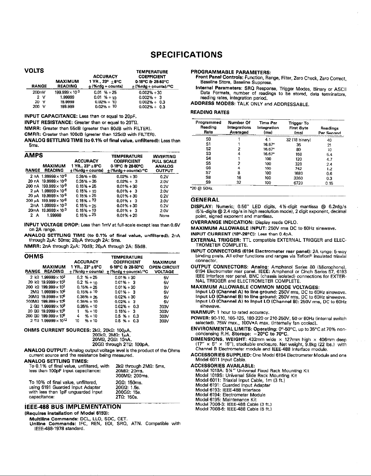
READING RATES
GENERAL
DISPLAY: Numeric: 0.56” LED digits, 4%.digit mantissa @ 6.2rdgis
(5%.digits @ 2.4 rdg/s in high resolution mode), 2 digit wponent, decimal
point, signed exponent and mantissa.
OVERRANGE INDICATION: Display reads OFLO.
MAXIMVM ALLOWABLE INPUT: 250” rms DC to SOHz sinswave.
INPUT CURRENT ,18=‘-28°C,: Less than 0.4pA.
EXTERNAL TRIGGER: TTL compatible EXTWNAL TRIGGER and ELEC-
TROMETER COMPLETE.
INPUT CONNECTORS 16194 Electrometer rear panel,: 2A range: 5-w”
binding posts. All other functions and ranges via Teflon” insulated ttisxial
connector.
OUTPUT CONNECTORS: Analog: Amphenol Series SO (MicrophoneI.
6194 Electrometer rear panel. IEEE: Amphenol or Cinch Series 57. 6193
IEEE Interface rear panel. SNC lchassis isolated) connecfions for EXTERNAL TRIGGER and ELECTROMETER COMPLETE,
MAXIMUM ALLOWABLE COMMON MODE VOLTAGES:
Input LO IChannel A) to line ground: 250” rms, DC to 60Hz sinewsve.
Input LO IChannel SI to line ground: 250” rms, DC to 60Hr sinewave.
Input LO IChannel A, to Input LO IChannel 61: 250” m,s, DC to SOHz
sinewave.
WARMUP: 1 hour to rated sccuracy.
POWER: 90-110, 105-125, 180-220 ar210-250”. 50 or 60Hz ,intemal switch
selected). 75W max., 100WA max. (intsmsllv fan cooled).
ENVIRONMENTAL LIMITS: Operstlng: On-50°C, up to 35OC at 70% non
condsnsina R.H. Storage: -2OOC to 70°C.
DIMENSIOk, WEIGH6 432mm wide x 127mm high x 406mm deep
(17” x 5” x V.7’~. stackable enclosure. Net weight, S.Skg 122 Ibs.1 with
Chsnnel S Electrometer module and IEEE-488 lntsfface module.
ACCESSORIES SUPPLIED: One Model 6194 Electrometer Module and one
Model 6011 input Cable.
ACCESSORIES AVAILASLE:
Model 1OlgA: 5%” Universal Fixed Rack Mounting Kit
Model 10195: Universal Slide Rack Mounting Kit
Model 6011: Trisxisl Input Cable. lm (3 ft.)
Model 6191: Guarded input Adapter
Model 6193: IEEE-488 Interface
Model 6194: Electrometer Module
Model 6195: Maintenance Kit
Model 7008-3: IEEE-488 Cable 13 ft.,
Made, 7009.6: IEEE-488 Cable 16 ft.,
 Loading...