

Page 1

Series 2600A
• Combines a power supply, true
current source, 6½-digit DMM,
arbitrary waveform generator,
V or I pulse generator with
measurement, electronic load,
and trigger controller – all in
one instrument
• Family of products offers wide
dynamic range: 1fA to 50A and
1µV to 200V
• 20,000 rdg/s provides faster
test times and ability to capture
transient device behavior
• Precision timing and channel
synchronization (<500ns)
• USB port for saving data and
test scripts
• LXI Class C compliance supports
high speed data transfer and
enables quick and easy remote
testing, monitoring, and
troubleshooting
• Software:
®
Express for quick and
– TSP
easy I-V test (embedded)
Scalable, integrated source and measure solutions
– ACS Basic Edition for
semiconductor component
characterization (optional)
System SourceMeter® Instruments
See page 26 for Model 2651A Single-Channel
System SourceMeter Instrument (High Power)
Series 2600A System SourceMeter instruments are Keithley’s latest I-V source measurement unit
(SMU) instruments for use as either bench-top I-V characterization tools or as building block components of multi-channel I-V test systems. For bench-top use, Series 2600A instruments feature an
embedded TSP Express Software Tool that allows users to quickly and easily perform common I-V
tests without programming or installing software. For system level applications, the Series 2600A’s
Test Script Processor (TSP) architecture, along with other new capabilities such as parallel test execution and precision timing, provides the highest throughput in the industry, lowering the cost of test.
To simplify the testing, verification, and analysis of semiconductor components, the optional ACS
Basic Edition software is also available.
Scalable, integrated source and measure solutions
CONNECT DUT CONFIGURE Test COLLECT Data
HI
SMU B
Sweep V
SMU A
Step V
G
Measure I
G
LO
Performing nested sweeps to characterize a transistor with TSP Express is quick and easy. Data can be exported to a .csv file for use with
spreadsheet applications such as Excel.
Quick and Easy Lab and
Bench-Top Use
Each Series 2600A SourceMeter instrument
is a complete I-V measurement solution with
unmatched ease of use, capability, and flexibility.
They simplify the process of making high-performance measurements.
SMU INSTRUMENTS
1.888.KEITHLEY
(U.S. only)
www.keithley.com
Measure I
LO
D
D
The TSP Express Software Tool quickly sets up
and runs basic and advanced tests, including:
nested step/sweeps, pulse sweeps, and custom
sweeps for device characterization applications.
The resulting data can be viewed in graphical or
tabular format and exported to a .csv file for use
with spreadsheet applications.
A GREATER ME ASURE OF C ONFIDENC E
TSP Express runs on a PC connected to the
SourceMeter instrument via an Ethernet cable
(provided with the instrument). The intuitive
user interface resides on the built-in LXI web
page, so no software installation is needed.
Page 2

Series 2600A
System SourceMeter® Instruments
Simplify Semiconductor Component
Test, Verification, and Analysis
The optional ACS Basic Edition software maximizes the
productivity of customers who perform packaged part characterization during development, quality verification, or failure
analysis, with:
• Rich set of easy-to-access test libraries
• Script editor for fast customization of existing tests
• Data tool for comparing results quickly
• Formulator tool that analyzes captured curves and provides
a wide range of math functions
For more information about the ACS Basic Edition software,
please refer to the ACS Basic Edition data sheet.
Unmatched Throughput and Flexibility
for High Performance I-V Test Systems
TSP technology provides remarkable capabilities when a Series
2600A is integrated as part of a multi-channel I-V test system.
When you need to acquire data on a packaged part quickly, the wizard-based user
interface of ACS Basic Edition makes it easy to find and run the test you want, like
this common FET curve trace test.
For example, the embedded scripting capability allows test
scripts to be run by the instrument. Test scripts are complete test programs based on an easy to use
but highly efficient and compact scripting language called Lua <www.lua.org>. Since test scripts
can contain any sequence of routines that are executable by conventional programming languages
(including decision making algorithms), this feature allows entire tests to be managed by the instrument without sending readings back to a PC for decision making. This eliminates the delays caused
Scalable, integrated source and measure solutions
by GPIB traffic congestion and greatly improves overall test times.
Also, TSP technology offers “mainframe-less channel expansion.” The TSP-Link channel expansion
bus (which uses a 100 Base T Ethernet cable) allows multiple Series 2600A and other TSP instruments to be connected in a master-slave configuration and behave as one integrated system. TSP-Link
technology supports up to 32 units or 64 SMU instrument channels per GPIB or IP address, making it
easy to scale a system to fit the particular requirements of an application.
Parallel Test Capability
The Series 2600A takes system level performance to a new height with parallel testing capability. This
feature tests multiple devices in parallel to meet the high throughput requirements of production test
and advanced semiconductor lab applications.
This parallel testing capability enables each instrument in the system to run its own complete test
sequence, creating a fully multi-threaded test environment. Hence, the number of tests that can be
running in parallel on a Series 2600A system can be as many as the number of instruments in the
system. In contrast, most conventional test systems run a single thread test, usually on the controller
PC instead of the instrument itself. Testing multiple devices at the same time means dramatically
improved test throughput and reduced overall
cost of test.
When all or some of your test requirements
change, your Series 2600A system can be reconfigured via software without rewiring. The internal software can match the different pin layouts
of the devices-under-test to the appropriate SMU
instrument-per-pin configurations.
Tight Timing and Synchronization
Today’s test engineers are challenged with
testing increasingly more complex and more
sensitive devices that require precise timing
and synchronization. Whether you need to
synchronize electrical and optical tests for an
<500ns
Scalable, integrated source and measure solutions
GPIB or Ethernet
TSP-Link
Parallel testing with the Series 2600A
1.888.KEITHLEY
Device 1
(U.S. only)
www.keithley.com
Test 1
running
To
Test 2
running
To
Device 2
Test 3
running
To
Device 3
A GREATER ME ASURE OF C ONFIDENC E
SMU1
SMU2
SMU3
SMU4
All channels in the system are synchronized
to under 500ns.
SMU INSTRUMENTS
Page 3

Series 2600A
System SourceMeter® Instruments
Ordering Information
2601A Single-channel System
2602A Dual-channel System
2611A Single-channel System
2612A Dual-channel System
2635A Single-channel System
2636A Dual-channel System
2651A Single-channel System
Accessories Supplied
Scalable, integrated source and measure solutions
2600-ALG-2
2600-Kit Mating Screw
CA-180-3A
TSP Express Software Tool
(embedded)
Test Script Builder Software
(supplied on CD)
ACS Basic Edition Software
(optional)
SourceMeter Instrument
(3A DC, 10A Pulse)
SourceMeter Instrument
(3A DC, 10A Pulse)
SourceMeter Instrument
(200V, 10A Pulse)
SourceMeter Instrument
(200V, 10A Pulse)
SourceMeter Instrument
(1fA, 10A Pulse)
SourceMeter Instrument
(1fA, 10A Pulse)
SourceMeter Instrument
(2000W, 50A Pulse)
Low Noise Triax Cable
with Alligator Clips,
2m (6.6 ft.) (two
supplied with 2636A,
one with 2635A)
Terminal Connec tors
with strain relief
and covers (2601A/
2602A/2611A/2612A)
TSP-Link/Ethernet
Cable (two per unit)
optoelectronic component or ensure that the same stress times are applied to the different pins of
an advanced semiconductor device, providing precision timing and synchronization between SMU
instrument channels (and external instruments) has become a critical requirement.
A high performance trigger model that is hardware driven allows timing at each source-measure step
to be tightly controlled. It also synchronizes the operations between SMU instrument channels and/
or external instrumentation at hardware speeds of <500ns.
Third-generation SMU Instrument
Design Ensures Faster Test Times
Based on the proven architecture of earlier Series 2600 instruments, the Series 2600A’s new SMU instrument design enhances
test speed in several ways. For example, while earlier designs
used a parallel current ranging topology, the Series 2600A uses
a patented series ranging topology, which provides faster and
smoother range changes and outputs that settle more quickly.
The Series 2600A SMU instrument design supports two modes
of operation for use with a variety of loads. In normal mode,
the SMU instrument provides high bandwidth performance for
maximum throughput. In high capacitance (high-C) mode, the
SMU instrument uses a slower bandwidth to provide robust performance with higher capacitive loads.
Each Series 2600A SMU instrument channel offers a highly flexible, four-quadrant source coupled with precision voltage and
current meters. Each channel can be configured as a:
• Precision power supply
• True current source
• DMM (DCV, DCI, ohms, and power with 6½-digit resolution)
Current arbitrary waveforms
maximum output update rates:
12,500 samples/second.
Voltage arbitrary waveforms
maximum output update rates:
20,000 samples/second.
• Electronic load (with sink mode capability)
• V or I pulse generator (Pulse width: 100µs and longer)
• V or I waveform generator
All analog-to-digital (A/D) converters in Series 2600A instruments are both high speed and high
precision for maximum flexibility. The two A/D converters per channel (one for I, one for V) can run
simultaneously, providing precise source-readback without sacrificing test throughput. These A/D
converters offer the versatility of programmable integration rates, allowing you to optimize for either
high speed (>20,000 rdgs/s at 0.001 NPLC setting) or for high resolution (up to 24 bits at 10 NPLC setting) measurements.
In addition to the high speed or high resolution modes, the Model 2651A offers a digitizing measurement mode that enables 1µs per point sampling. See the Model 2651A on page 26 for more information.
Digital I/O Interface
A back panel port on every Series 2600A instrument provides 14 bits of universal digital I/O to link
the instrument to a variety of popular component handlers and/or probe stations. These digital I/O
lines are compatible with the triggering technology of Keithley’s earlier Trigger-Link instruments.
These lines simplify integrating Series 2600A instruments into systems that employ other electrical,
mechanical, optical, or RF equipment.
Scalable, integrated source and measure solutions
SMU INSTRUMENTS
1.888.KEITHLEY
www.keithley.com
TSP-Link Trigger Lines
The TSP-Link bus supports dedicated trigger lines that provide synchronous operations between multiple Series 2600A instruments (and other TSP instruments, such as Series 3700 DMM/Switch Systems)
without the need for additional trigger connections.
(U.S. only)
A GREATER ME ASURE OF C ONFIDENC E
Page 4

Series 2600A
System SourceMeter® Instruments
TYPICAL APPLICATIONS
I-V functional test and
characterization of a
wide range of devices,
including:
• Discrete and passive
components
–Two-leaded –
Sensors, disk
drive heads, metal
oxide varistors
(MOVs), diodes,
zener diodes,
sensors, capacitors,
thermistors
– Three-leaded –
Small signal bipolar
junction transistors
(BJTs), field-effect
transistors (FETs),
and more
• Simple ICs – Optos,
drivers, switches,
sensors
• Integrated devices –
small scale integrated
(SSI) and large scale
integrated (LSI)
Scalable, integrated source and measure solutions
–Analog ICs
–Radio frequency
integrated circuits
(RFICs)
– Application specific integrated
circuits (ASICs)
– System on a chip (SOC) devices
• Optoelectronic devices such as lightemitting diodes (LEDs), laser diodes,
high brightness LEDs (HBLEDs),
vertical cavity surface-emitting lasers
(VCSELs), displays
• Wafer level reliability
– NBTI, TDDB, HCI, electromigration
• Solar Cells
• Batteries
Built-in Contact Check Function
The Contact Check function makes it simple to verify good device-under-test connections quickly and
easily before an automated test sequence begins. This eliminates the measurement errors and false
product failures associated with contact fatigue, breakage, contamination, loose or broken connections, relay failures, etc.
Powerful Software Tools
In addition to the embedded TSP Express and optional ACS Basic Edition software, the free Test
Script Builder software tool is provided to help users create, modify, debug, and store TSP test
scripts. Table 1 describes key features of Series 2600A software tools.
Complete Automated System Solutions
While the ACS Basic Edition software only supports component characterization tests, wafer and cassette level testing can be performed
by Keithley’s ACS Integrated Test Systems. ACS systems are highly
configurable, instrument-based systems that generally include a
number of Series 2600A instruments. These systems are designed for
semiconductor device characterization, reliability/WLR, parametric,
and component functional testing.
The flexible software architecture of ACS Basic Edition allows configuring
systems with a wide range of controllers and test fixtures, as well as the
exact number of SourceMeter instruments the application requires.
Table 1. Series 2600A software tools
Feature/
Functionalit y
Description
Supported
hardware
Supported
buses
Functionality
Data
management
Installation
ACS Basic Edition
Semiconductor characterization
software for component test,
verification, and analysis
24xx, 26x xA, 4200-SCS, 237
GPIB, Ethernet
Intuitive, wizard-based GUI,
Rich set of test libraries
Formulator tool with wide range
of math functions
Optional purchase
TSP Express
Quick Start Tool for fast and easy
I-V testing, primarily for bench
and lab users
26xxA 26xxA, 37xx
Ethernet only
Linear/Log Sweeps, Pulsing,
Custom sweeps, Single point
source-measures. Note: Uses
new 2600A’s new API’s for
precision timing and channel
synchronization
.csv export, basic curve
tracing (no math formula or
analysis support)
Not necessary.
Embedded in the instrument.
Example ACS Integrated
Test System
Test Script
Builder (TSB )
Custom script
writing tool for TSP
instruments
GPIB, RS-232,
Ethernet
Custom scripts with
total fl exibility
N/A
Free Download or
CD Install on PC.
Scalable, integrated source and measure solutions
SMU INSTRUMENTS
1.888.KEITHLEY
www.keithley.com
(U.S. only)
A GREATER ME ASURE OF C ONFIDENC E
Page 5

Series 2600A
System SourceMeter® Instruments
In the first and third quadrants, Series 2600A instruments operate as a
source, delivering power to a load. In the second and fourth quadrants,
they operate as a sink, dissipating power internally.
+10A
+5A
+3A
+1.5A
+1A
0A
–1A
–1.5A
–3A
–5A
–10A
+35V–35V–40V
–6V
Models 2601A and 2602A I-V capability
+10A
Scalable, integrated source and measure solutions
+1.5A
+1A
+0.1A
–0.1A
–1A
–1.5A
–10A
0A
–5V
Models 2611A and 2612A I-V capability
+20V–20V 0V
+20V–20V 0V
+40V+6V
+200V+5V
+180V–180V–200V
DC
Pulse
DC
Pulse
ACCESSORIES AVAILABLE*
CABLES AND CONNECTORS
2600-BAN Banana Test Leads/Adapter Cable. For a single
2600-KIT Extra screw terminal connector, strain relief, and cover for a single SourceMeter
2600-TRIAX Triax Adapter. For a single 2601A /2602A/2611A/2612A SMU instrument channel
7078-TRX-* 3-Slot, Low Noise Triax Cable. For use with 2600-TR IA X Adapter
7078-TRX-GND 3-Slot male triax to BNC adapter (guard removed)
8606 High Performance Modular Probe Kit. For use with 2600A-BAN
SC-200 Shielded Twisted Pair Cable. Recommended for general-purpose
DIGITAL I/O, TRIGGER LINK, AND TSP-LINK
2600-TLINK Digital I/O to TLINK Adapter Cable, 1m
CA-126-1 Digital I /O and Trigger Cable, 1.5m
CA-180-3A CAT5 Crossover Cable for TSP-Link and direct Ethernet connection (two supplied)
GPIB INTERFACES AND CABLES
7007-1 Double Shielded GPIB Cable, 1m (3.3 ft.)
7007-2 Double Shielded GPIB Cable, 2m (6.6 ft.)
KPCI- 488LPA IEEE-488 Interface/Controller for the PCI Bus
KPXI-488 IEEE-488 Interface Board for the PXI Bus
KUSB-488B IEEE-488 USB-to-GPIB Interface Adapter
SWITCHING
Series 3700 DMM/Switch Systems
707A Semiconductor Switching Matrix Mainframe
7001 Switch Control Mainframe
RACK MOUNT KITS
4299-1 Single Rack Mount Kit with front and rear support
4299-2 Dual R ack Mount Kit with front and rear suppor t
4299-5 1U Vent Panel
SOFTWARE
ACS-BASIC Component Characteri zation Software
EXTENDED WARRANTIES
2601A-EW 1 Year Extended Warranty for Model 2601A
2602A-E W 1 Year Extended Warranty for Model 2602A
2611A-EW 1 Year Extended Warranty for Model 2611A
2612A-EW 1 Year Ex tended Warranty for Model 2612A
2635A-EW 1 Year Extended Warranty for Model 2635A
2636A-EW 1 Year Extended Warranty for Model 2636A
CALIBRATION AND VERIFICATION
2600-STD-RES Calibration Standard 1GΩ Resistor for Models 2635A and 2636A
*See page 27 for Model 2651A accessories.
2601A/2602A/2611A/2612A SMU instrument channel
channel (one supplied with 2601A /2611A, two with 2602A/2612A)
use with Series 2600A System SourceMeter instruments
Scalable, integrated source and measure solutions
+10A
+1.5A
+1A
+0.1A
0A
–0.1A
–1A
–1.5A
–10A
Models 2635A and 2636A I-V capability Model 2651A I-V capability
SMU INSTRUMENTS
1.888.KEITHLEY
–5V
(U.S. only)
+20V–20V 0V
+180V–180V–200V
www.keithley.com
DC
Pulse
+200V+5V
A GREATER ME ASURE OF C ONFIDENC E
+50A
+20A
+10A
+5A
–5A
–10A
–20A
–50A
0A
–10V
+10V
DC and
Pulse
Pulse
only
+20V–20V 0V
+40V–40V
Page 6

2601A
2602A
System SourceMeter® Instruments
SPECIFICATION CONDITIONS
This document contains specifications and supplemental information for the Models 2601A and
2602A System SourceMeter
Models 2601A and 2602A are tested. Upon leaving the factory, the 2601A and 2602A meet these
specifications. Supplemental and typical values are non- warranted, apply at 23°C, and are provided
solely as useful information.
Accuracy specifications are applicable for both normal and high capacitance modes.
The source and measurement accuracies are specified at the SourceMeter CHANNEL A (2601A
and 2602A) or SourceMeter CHANNEL B (2602A) ter minals under the following conditions:
1. 23°C ± 5°C, <70% relative humidity
2. After 2 hour warm-up
3. Speed normal (1 NPLC)
4. A/D auto-zero enabled
5. Remote sense operation or properly zeroed local operation
6. Calibration period = 1 year
®
instruments. Specifications are the standards against which the
SOURCE SPECIFICATIONS
VOLTAGE SOURCE SPECIFICATIONS
VOLTAGE PROGRAMMING ACCURACY
Range
100.000 mV 5 µV 0.02% + 250 µV 20 µV
Series 2600A specifications
1.00000 V 50 µV 0.02% + 400 µV 50 µV
6.00000 V 50 µV 0.02% + 1.8 mV 100 µV
40.0000 V 500 µV 0.02% + 12 mV 500 µV
TEMPERATUR E COEFFICIENT (0°–18°C and 28°–50°C)
Applicable for normal mode only. Not applicable for high capacitance mode.
MAXIMUM OUTPUT POW ER AND SOURCE/SINK LIMITS
±40.4V @ ±1.0A, ±6.06V @ ±3.0A, four quadrant source or sink operation.
VOLTAGE REGUL ATION: Line: 0.01% of range. Load: ±(0.01% of range + 100µV).
NOISE 10Hz–20MHz: <20mV peak-peak (typical), <3mV RMS (typical), 6V range.
CURRENT LIMIT/COMPLIANCE
Minimum value is 10nA. Accuracy same as current source.
OVER SHOOT: <±(0.1% + 10mV) typical. Step size = 10% to 90% of range, resistive load,
maximum current limit/compliance.
GUARD OFFSET VOLTAGE: <4mV typical. Current <10mA.
Programming
Resolution
4
: Bipolar current limit (compliance) set with single value.
CURRENT SOURCE SPECIFICATIONS
CURRENT PROGRAMMING ACCUR ACY
5
5
5, 6
Programming
Resolution
10 µA 0.05% + 1.8 mA 70 µA
10 µA 0.06% + 4 mA 150 µA
100 µA 0.5 % + 40 mA (typical)
9
: Bipolar voltage limit (compliance) set with a single value.
Range
100.000 nA 1 pA 0.06% + 100 pA 5 pA
1.00000 µA 10 pA 0.03% + 800 pA 25 pA
10.0000 µA 100 pA 0.03% + 5 nA 60 pA
100.000 µA 1 nA 0.03% + 60 nA 3 nA
1.00000 mA 10 nA 0.03% + 300 nA 6 nA
10.0000 mA 100 nA 0.03% + 6 µA 200 nA
100.000 mA 1 µA 0.03% + 30 µA 600 nA
1.00000 A
3.00000 A
10.0000 A
TEMPERATUR E COEFFICIENT (0°–18°C and 28°–50°C)
MAXIMUM OUTPUT POW ER AND SOURCE/SINK LIMITS
±1.01A @ ±40.0V, ±3.03A @ ±6.0V, four quadrant source or sink operation.
CURR ENT REGULATION: Line: 0.01% of range. Load: ±(0.01% of range + 100pA).
VOLTAGE LIMIT/COMPLIANCE
Minimum value is 10mV. Accurac y is the same as voltage source.
OVER SHOOT: <±0.1% typical (step size = 10% to 90% of range, resistive load; see Current Source
Output Settling Time for additional test conditions).
1
Accuracy (1 Year)
23°C ±5°C
±(% rdg. + volts)
2
: ±(0.15 × accuracy specification)/°C.
3
: 40.4W per channel maximum.
Accuracy (1 Year)
23°C ±5°C
±(% rdg. + amps)
7
: ±(0.15 × accuracy specification)/°C.
8
: 40.4W per channel maximum.
Typical Noise
(peak-peak)
0.1Hz–10Hz
Typical Noise
(peak-peak)
0.1Hz–10Hz
ADDITIONAL SOURCE SPECIFICATIONS
TRA NSIENT R ESPONSE TIME: <70µs for the output to recover to within 0.1% for a 10% to 90%
step change in load.
VOLTAGE SOURCE OUTPUT SETTLING TIME: Time required to reach within 0.1% of final value
after source level command is processed on a fixed range.
100mV, 1V Ranges: <50µs t ypical.
6V Ran ge: <10 0µs typical.
40V R ange
CURR ENT SOURCE OUTPUT SETTLING TIME: Time required to reach within 0.1% of final value
3A Range: <80µs typical (current less than 2.5A, R
1A–10mA Ranges: <80µs t ypical (R
1mA Range: <100µ s ty pical.
100 µA Range: <150µs typical.
10µA R ange: <500µs typical.
1µA Range: <2.5ms typical.
100nA Range: <25ms t ypical.
DC FLOATING VOLTAGE: Output can be floated up to ±250VDC from chassis ground.
REMOTE SENSE OPERAT ING RA NGE
VOLTAGE OUTPUT HE ADROOM:
OVER TEMPERATURE PROTECTION: Internally sensed temperature overload puts unit in
VOLTAGE SOURCE RANGE CHA NGE OVERSHOOT: <300mV + 0.1% of larger range (typical).
CURRENT SOURCE RANGE CHANGE OVERSHOOT: <5% of larger range + 300mV/R
NOTES
1. Add 50µV to source accuracy specifications per volt of HI lead drop.
2. High Capacitance Mode accuracy is applicable at 23°C ±5°C only.
3. Full power source operation regardless of load to 30°C ambient. Above 30°C and/or power sink operation,
4. For sink mode operat ion (quadrants II and I V), add 0.06% of limit range to the corresponding current lim it
5. Full power source operation regardless of load to 30°C ambient. Above 30°C and/or power sink operation,
6. 10A range accessible only in pulse mode.
7. High Capacitance Mode accuracy is applicable at 23°C ±5°C only.
8. Full power source operation regardless of load to 30°C ambient. Above 30°C and/or power sink operation,
9. For sink mode operat ion (quadrants II and I V), add 10% of compl iance range and ±0.02% of limit setting to
10. Add 150µs when measuri ng on the 1A range.
11. Add 50µV to source accuracy specifications per volt of HI lead drop.
10
: <150µs ty pica l.
× R
after source level command is processed on a fixed range. Values below for I
unless noted.
>6Ω).
load
11
Maximum voltage between HI and SENSE HI = 3V .
Maximum voltage between LO and SENSE LO = 3V .
40V Range: Max. output voltage = 42V – total voltage drop across source leads (maximum 1Ω
per source lead).
6V Ra nge: Max. output voltage = 8V – total voltage drop across source leads (maximum 1Ω per
source lead).
standby mode.
Overshoot into an 100kΩ load, 20MHz BW.
with source settling set to SETTLE_SMOOTH_100NA). See Current Source Output Settling Time
for additional test conditions.
refer to “Operating Boundaries” in the Series 2600A Reference Manual for additional power derating
information.
accuracy specifications. Specifications apply with sink mode operation enabled.
refer to “Operating Boundaries” in the Series 2600A Reference Manual for additional power derating
information.
refer to “Operating Boundaries” in the Series 2600A Reference Manual for additional power derating
information.
corresponding volta ge source spe cification. For 100mV range add an addit ional 60mV of uncertainty.
:
load
>2Ω).
= 1V
out
load
(typical
load
Series 2600A specifications
SMU INSTRUMENTS
1.888.KEITHLEY
www.keithley.com
(U.S. only)
A GREATER ME ASURE OF C ONFIDENC E
Page 7

2601A
2602A
System SourceMeter® Instruments
SOURCE SPECIFICATIONS (continued)
PULSE SPECIFICATIONS
Region
Current Limit
1 1 A @ 40 V DC, no limit 100%
1 3 A @ 6 V DC, no limit 100%
2 1.5 A @ 40 V 100 ms 25%
3 5 A @ 35 V 4 ms 4%
4 10 A @ 20 V 1.8 ms 1%
MINIMUM PROGRAMMABLE PULSE WIDTH
source at a given I/V output and load can be longer than 100µs.
PULSE WIDTH PROGRAMMING RESOLUTION: 1µs.
PULSE WIDTH PROGRAMMING ACCURACY
PULSE WIDTH JITTER: 2µs (typical).
QUADRANT DIAGRAM:
Maximum
+10A
4
1
4
–6V
Series 2600A specifications
+5A
+3A
+1.5A
+1A
–1A
–1.5A
–3A
–5A
–10A
3
2
0A
2
3
NOTES
12. Times mea sured from the star t of pulse to the start off-time; see fig ure below.
Pulse Level
Start t
on
Bias Level
13. Thermally limited in sin k mode (quadrants II and IV ) and ambient temper atures above 30°C. See power equations in the reference m anual for more inform ation.
14. Typical performance for minimum settled pulse widths:
6 V
20 V
35 V
40 V
1.5 A
3 A
5 A
10 A
Typical tests were performed using remote operation, 4W sense, and best, fixed measurement range. For more
information on pul se scripts, see the Ser ies 2600A Reference Manual.
15. Times mea sured from the star t of pulse to the start off-time; see fig ure below.
Pulse Level
Bias Level
SMU INSTRUMENTS
10%
Source Value Load
Start t
on
10%
90%
Start t
off
t
on
2 Ω
2 Ω
7 Ω
27 Ω
27 Ω
2 Ω
7 Ω
2 Ω
90%
Start t
off
t
on
Maximum
Pulse Width
14, 15
: 100µs. NOTE: Minimum pulse width for settled
15
: ±5µs.
2
2
+20V–20V 0V
t
off
Source Settling
0.2% 150 µs
1% 2 00 µs
0.5% 500 µs
0.1% 400 µs
0.1% 1.5 ms
0.2% 150 µs
0.5% 500 µs
0.5% 200 µs
t
off
12
3
3
+35V–35V–40V
10%
(% of range) Min. Pulse Width
10%
Maximum
Duty Cycle
DC
Pulse
Pulse
Pulse
+40V+6V
METER SPECIFICATIONS
VOLTAGE MEASUREMENT ACCURACY
13
Range
100.000 mV 1 µV
1.00000 V 10 µV
6.00000 V 10 µV
40.0000 V 100 µV
TEMPERATUR E COEFFICIENT (0°–18°C and 28°–50°C)
Applicable for normal mode only. Not applicable for high capacitance mode.
Default Display
Resolution
18
CURRENT MEASUREMENT ACCURACY
Range
Resolution
100.000 nA 1 pA <1 mV 0.05% + 100 pA
1.00000 µA 10 pA <1 mV 0.025% + 500 pA
10.0000 µA 100 pA <1 mV 0.025% + 1.5 nA
100.000 µA 1 nA <1 mV 0.02% + 25 n A
1.00000 mA 10 nA <1 mV 0.02% + 200 nA
10.0000 mA 100 nA <1 mV 0.02% + 2.5 µA
100.000 m A 1 µA <1 mV 0.02% + 20 µA
1.00000 A 10 µA <1 mV 0.03% + 1.5 mA
Default Display
3.00000 A 10 µA <1 mV 0.05% + 3.5 mA
10.0000 A
22
100 µA <1 mV 0.4% + 25 mA (typical)
CURR ENT MEASURE SETTLING T IME (Time for measurement to settle after a V
required to reach within 0.1% of final value after source level command is processed on a fixed
range. Values for V
= 1V unless noted. Current R ange: 1mA. Settling Time: <100µs (typical).
out
TEMPERATUR E COEFFICIENT (0°–18°C and 28°–50°C)
Applicable for normal mode only. Not applicable for high capacitance mode.
CONTACT CHECK
25
Maximum Measurement
Speed
Time To Memory
For 60Hz (50Hz)
FAST 1 (1.2) ms
MEDIUM 4 (5) ms
SLOW 36 (42) ms
Voltage
20
Burden
ADDITIONAL METER SPECIFICATIONS
MAXIMUM LOAD IMPEDANCE:
Normal Mode: 10n F (ty pical). High Capacitance Mode: 50µF (typical).
COMMON MODE VOLTAGE: 250VDC.
COMMON MODE ISOLATION: >1GΩ, <4500pF.
OVER RANGE: 101% of source range, 102% of measure range.
MAXIMUM SENSE LEAD RESISTANCE: 1kΩ for rated accuracy.
SENSE INPUT IMPEDANCE: >10 GΩ.
NOTES
16. Add 50µV to source accuracy specifications per volt of HI lead drop.
17. De-rate a ccurac y specifications for NPLC setting < 1 by increasing error term.
Add appropr iate % of range term using table below.
NPLC Setting
0.1 0.01% 0.01% 0.01% 0.01% 0.01%
0.01 0.08% 0.07% 0.1% 0.05% 0.05%
0.001 0.8 % 0 .6 % 1% 0.5 % 1.1 %
18. Applies when in single channel d isplay mode.
19. High Capacitance Mode accuracy is applicable for 23°C ±5°C only.
20. Applies when in single channel d isplay mode.
21. Four-wire remote sense only with current meter mode selec ted. Voltage measure set to 10 0mV or 1V range on ly.
22. 10A range accessible only in pulse mo de.
23. Compliance equal to 100mA.
24. High Capacitance Mode accuracy is applicable for 23°C ±5°C only.
25. Includes measurement of SENSE HI to HI and SENSE LO to LO contact resistances.
100mV
Range
1V–4 0V
Ranges
16, 17
Input
Resistance
>10 GΩ
>10 GΩ
>10 GΩ
>10 GΩ
19
: ±(0.15 × accuracy specification)/°C.
17
Accuracy (1 Year)
21
±(% rdg. + amps)
24
: ±(0.15 × accuracy specification/°C.
Accuracy (1 Year)
±(% rdg. + ohms)
5% + 10 Ω
5% + 1 Ω
5% + 0.3 Ω
100nA
Range
1µA–100m A
Ranges
Accuracy (1 Year)
23°C ±5°C
±(% rdg. + volts)
0.015% + 150 µV
0.015% + 200 µV
0.015% + 1 mV
0.015% + 8 mV
23°C ±5°C
23
)
: Time
step
23°C ±5°C
1A–3A
Ranges
Series 2600A specifications
1.888.KEITHLEY
www.keithley.com
(U.S. only)
A GREATER ME ASURE OF C ONFIDENC E
Page 8
2601A
2602A
System SourceMeter® Instruments
HIGH CAPACITANCE MODE
26, 27, 28
VOLTAGE SOURCE OUTPUT SETTLING TIME: Time required to reach 0.1% of final value after
source level command is processed on a fixed range. Current limit = 1A.
Voltage Source Range Settling Time with C
100 mV 200 µs (typical)
load
= 4.7µF
1 V 200 µs (typical)
6 V 200 µs (typical)
40 V 7 ms (typical)
CURR ENT MEASURE SETTLING TIME: Time required to reach 0.1% of final value after voltage
source is stabilized on a fixed range. Values below for V
Current Measure Range Settling Time
3 A – 1 A <120 µs (typical) (R
100 mA – 10 mA <100 µs (typical)
= 1V unless noted.
out
> 2Ω)
load
1 mA < 3 ms (typical)
100 µA < 3 ms (typical)
10 µA < 230 ms (typical)
1 µA < 230 ms (typical)
29
CAPACITOR LEAK AGE PERFORMA NCE USING HIGH-C SCRIPTS
Test: 5V step and measure. 200ms (typical) @ 50nA.
: Load = 5µF||10MΩ.
IEEE-488: IEEE-488.1 compliant. Supports IEEE-488.2 common commands and status model
topology.
Series 2600A specifications
RS-232: Baud rates from 300bps to 115200bps. Programmable number of data bits, parity
type, and flow control (RTS/CTS hardware or none). When not programmed as the active
host interface, the SourceMeter instrument can use the RS-232 interface to control other
instrumentation.
ETHERNET: RJ-45 connector, LXI Class C, 10/100BT, no auto MDIX.
EXPANSION INTERFACE: The TSP-Link expansion interface allows TSP enabled instruments to
trigger and communicate with each other.
Cable Type: Category 5e or higher LAN crossover cable.
Length: 3 meters maximum between each TSP enabled instrument.
LXI COMPLIANCE: LXI Class C 1.2.
LXI TIMING: Total Output Trigger Response Time: 245µs min., 280µs typ., (not speci-
fied) ma x. Receive LAN[0-7] Event Delay: Unknown. Generate LAN[0-7] Event Delay:
Unknow n.
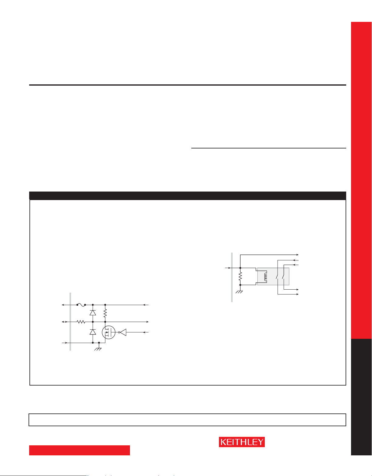
DIGITAL I/O INTERFACE:
600mA
Solid State
+5V Pin
(on DIGITAL I/O
connector)
Digital I/O Pin
(on DIGITAL I/O
connector)
GND Pin
(on DIGITAL I/O
connector)
Fuse
100Ω
Rear Panel
5.1kΩ
+5VDC
Read by
firmware
Written by
firmware
Connector: 25-pin female D.
Input/Output Pins: 14 open drain I/O bits.
Absolute Ma ximum Input Voltage: 5.25V.
Absolute Minimum Input Voltage: –0.25V.
Maximum Logic Low Input Voltage: 0.7V, +850µA max.
MODE CHANGE DELAY:
100µA Cur rent Range and Above:
Delay into High Capacitance Mode: 10m s.
Delay out of High Capacitance Mode: 10ms.
1µA and 10µA Current R anges:
Delay into High Capacitance Mode: 230ms.
Delay out of High Capacitance Mode: 10ms.
VOLTMETER INPUT IMPEDANCE: 10G Ω in parallel with 3300pF.
NOISE, 10Hz–20MHz (6V Range): <30mV peak-peak (typical).
VOLTAGE SOURCE RANGE CHA NGE OVERSHOOT: <400mV + 0.1% of larger range (typical).
Overshoot into a 100kΩ load, 20MHz BW.
NOTES
26. High Capa citance Mode specif ications a re for DC measurements only.
27. 100nA range is not available i n High Capac itance Mode.
28. High Capacitance Mode utilizes locked ranges. Auto Ra nge is disabled.
29. Part of K I Factory script s. See reference manual for detai ls.
GENERAL
Minimum Logic High Input Voltage: 2.1V, +570µA.
Maxi mum Source Current (flowing out of Digital I/O bit): +960µA.
Maximum Sink Current @ Ma ximum Logic Low Voltage (0.7V): –5.0mA.
Absolute Ma ximum Sink Current (flowing into Digital I/O pin): –11mA.
5V Power Supply Pin: Limited to 600mA, solid state fuse protected.
Safety Interlock Pin: Active high input. >3.4V @ 24mA (absolute maximum of 6V) must be
externally applied to this pin to ensure 200V operation. This signal is pulled down to chas-
sis ground with a 10kΩ resistor. 200V operation will be blocked when the INTERLOCK
signal is <0.4V (absolute minimum – 0.4V). See figure below:
Coil
10kΩ
Chassis
Ground
Resistance
145Ω ±10%
INTERLOCK Pin
(on DIGITAL I/O
*
connector)
Rear Panel
USB: USB 1.0 Host Controller (Memory Stick I/O).
POWER SUPPLY: 100V to 250VAC, 50 –60Hz (auto sensing), 240VA max.
COOLING: Forced air. Side intake and rear exhaust. One side must be unobstructed when rack
mounted.
EMC: Conforms to European Union Directive 2004/108/EEC, EN 61326-1.
SAFET Y: Conforms to European Union Directive 73/23/EEC, EN 61010-1, and UL 61010-1.
DIMENSIONS: 89mm high × 213mm wide × 460mm deep (3½ in × 8
Configuration (with handle and feet): 104mm high × 238mm wide × 460mm deep (4
3
⁄8 in × 17½ i n).
9
WEIGHT: 2601A: 4.75kg (10.4 lbs). 2602A: 5.50kg (12.0 lbs).
ENVIRONMENT: For indoor use only.
Altitude: Maximum 2000 meters above sea level.
Operating: 0°–50°C, 70% R.H. up to 35°C. Derate 3% R.H./°C, 35°–50°C.
Storage: –25°C to 65°C.
Read by firmware
+220V Supply
–220V Supply
To output stage
3
⁄8 in × 17½ in). Bench
1
⁄8 in ×
Series 2600A specifications
SEE PAGES 24 AND 25 FOR MEASUREMENT SPEEDS AND OTHER SPECIFICATIONS.
1.888.KEITHLEY
www.keithley.com
SMU INSTRUMENTS
(U.S. only)
A GREATER ME ASURE OF C ONFIDENC E
Page 9

2611A
2612A
System SourceMeter® Instruments
SPECIFICATION CONDITIONS
This document contains specifications and supplemental information for the Models 2611A and
2612A System SourceMeter
Models 2611A and 2612A are tested. Upon leaving the factory the 2611A and 2612A meet these
specifications. Supplemental and typical values are non- warranted, apply at 23°C, and are provided
solely as useful information.
Accuracy specifications are applicable for both normal and high capacitance modes.
The source and measurement accuracies are specified at the SourceMeter CHANNEL A (2611A and
2612A) or SourceMeter CHANNEL B (2612A) terminals under the following conditions:
1. 23°C ± 5°C, <70% relative humidity.
2. After 2 hour warm-up.
3. Speed normal (1 NPLC).
4. A/D auto-zero enabled.
5. Remote sense operation or properly zeroed local sense operation.
6. Calibration period = 1 year.
®
instruments. Specifications are the standards against which the
SOURCE SPECIFICATIONS
VOLTAGE SOURCE SPECIFICATIONS
VOLTAGE PROGRAMMING ACCURACY
Programming
Range
200.000 mV 5 µV 0.02% + 375 µV 20 µV
Series 2600A specifications
2.00000 V 50 µV 0.02% + 600 µV 50 µV
Resolution
20.0000 V 500 µV 0.02% + 5 mV 300 µV
200.000 V 5 mV 0.02% + 50 mV 2 mV
TEMPERATUR E COEFFICIENT (0°–18°C and 28°–50°C)
Applicable for normal mode only. Not applicable for high capacitance mode.
MAXIMUM OUTPUT POW ER AND SOURCE/SINK LIMITS
±20.2V @ ±1.5A, ±202V @ ±100mA, four quadrant source or sink operation.
VOLTAGE REGUL ATION: Line: 0.01% of range. Load: ±(0.01% of range + 100µV).
NOISE 10Hz–20MHz: <20mV peak-peak (typical), <3mV RMS (typical), 20V range.
CURRENT LIMIT/COMPLIANCE
Minimum value is 10n A. Accuracy is the same as current source.
OVER SHOOT: <±(0.1% + 10mV) (typical). Step size = 10% to 90% of range, resistive load, maxi-
mum current limit/compliance.
4
: Bipolar current limit (compliance) set with single value.
GUARD OFFSET VOLTAGE: <4mV (current <10mA).
CURRENT SOURCE SPECIFICATIONS
CURRENT PROGRAMMING ACCUR ACY
6
6
6, 7
Programming
Resolution
20 µA 0.05% + 1.8 mA 70 µA
50 µA 0.06% + 4 mA 150 µA
200 µA 0.5% + 40 mA (typical)
10
: Bipolar voltage limit (compliance) set with a single value.
Range
100.000 nA 2 pA 0.06% + 100 pA 5 pA
1.00000 µA 20 pA 0.03% + 800 pA 25 pA
10.0000 µA 200 pA 0.03% + 5 nA 60 pA
100.000 µA 2 nA 0.03% + 60 nA 3 nA
1.00000 mA 20 nA 0.03% + 300 nA 6 nA
10.0000 mA 200 nA 0.03% + 6 µA 200 nA
100.000 mA 2 µA 0.03% + 30 µA 600 nA
1.00000 A
1.50000 A
10.0000 A
TEMPERATUR E COEFFICIENT (0°–18°C and 28°–50°C) 8: ±(0.15 × accuracy specification)/°C.
Applicable for normal mode only. Not applicable for high capacitance mode.
MAXIMUM OUTPUT POW ER AND SOURCE/SINK LIMITS
±1.515A @ ±20V , ±101mA @ ±200V , four quadrant source or sink operation.
CURR ENT REGULATION: Line: 0.01% of range. Load: ±(0.01% of range + 100pA).
VOLTAGE LIMIT/COMPLIANCE
Minimum value is 20mV. Accuracy is the same as voltage source.
OVER SHOOT: <±0.1% (typical). Step size = 10% to 90% of range, resistive load; see Current
Source Output Settling Time for additional test conditions.
SMU INSTRUMENTS
1
Accuracy (1 Year)
23°C ±5°C
±(% rdg. + volts)
2
: ±(0.15 × accuracy specification)/°C.
3
: 30.3W per channel maximum.
5
Accuracy (1 Year)
23°C ±5°C
±(% rdg. + amps)
9
: 30.3W per channel maximum.
Typical Noise
(Peak-Peak)
0.1Hz–10Hz
Typical Noise
(Peak-Peak)
0.1Hz–10Hz
ADDITIONAL SOURCE SPECIFICATIONS
TRA NSIENT R ESPONSE TIME: <70µs for the output to recover to within 0.1% for a 10% to 90%
step change in load.
VOLTAGE SOURCE OUTPUT SETTLING TIME: Time required to within reach 0.1% of final value
after source level command is processed on a fixed range.
Range Settling Time
200 mV <50 µs (typical)
2 V <50 µs (typical)
20 V <110 µs (typical)
200 V <700 µs (typical)
CURR ENT SOURCE OUTPUT SETTLING TIME: Time required to reach
source level command is processed on a fixed range. Values below for I
Current Range Settling Ti me
1.5 A – 1 A <120 µs (typical) (R
100 mA – 10 mA <80 µs (typical)
1 mA <100 µs (typical)
100 µA <150 µs (typical)
10 µA <50 0 µs (typical)
1 µA <2 ms (typical)
100 n A <20 ms (typical)
DC FLOATING VOLTAGE: Output can be floated up to ±250VDC from chassis ground.
REMOTE SENSE OPERAT ING RA NGE
Maximum voltage between LO and SENSE LO = 3V .
VOLTAGE OUTPUT HE ADROOM:
200V Range: Max. output voltage = 202.3V – total voltage drop across source leads (maximum
1Ω per source lead).
20V Range: Max. output voltage = 23.3V – total voltage drop across source leads (maximum
1Ω per source lead).
OVER TEMPERATURE PROTECTION: Internally sensed temperature overload puts unit in
standby mode.
VOLTAGE SOURCE RANGE CHA NGE OVERSHOOT: <300mV + 0.1% of larger range (typical).
Overshoot into a 200kΩ load, 20MHz BW.
CURRENT SOURCE RANGE CHANGE OVERSHOOT: <5% of larger range + 300mV/R
– With source settling set to SETTLE_SMOOTH_100NA). See Current Source Output Settling
Time for additional test conditions.
> 6Ω)
load
11
: Maximum voltage between HI and SENSE HI = 3V .
within
0.1% of final value after
· R
= 2V unless noted.
out
load
(typical
load
NOTES
1. Add 50µV to source accuracy specifications per volt of HI lead drop.
2. High Capacitance Mode accuracy is applicable at 23°C ±5°C only.
3. Full power source operation regardless of load to 30°C ambient. Above 30°C and/or power sink operation,
refer to “Op erating Bounda ries” in the Series 2600A Reference Manua l for additional power derati ng information.
4. For sink mode operat ion (quadrants II and I V), add 0.06% of limit range to the corresponding current lim it
accuracy specifications. Specifications apply with sink mode operation enabled.
5. Accu racy specifications do not include connec tor leaka ge. Derate accuracy by V
between 18°–28°C. Derate accu racy by V
6. Full power source operation regardless of load to 30°C ambient. Above 30°C and/or power sink operation,
refer to “Op erating Bounda ries” in the Series 2600A Reference Manua l for additional power derati ng information.
7. 10A range accessible only in pulse mode.
8. High Capacitance Mode accuracy is applicable at 23°C ±5°C only.
9. Full power source operation regardless of load to 30°C ambient. Above 30°C and/or power sink operation,
refer to “Op erating Bounda ries” in the Series 2600A Reference Manua l for additional power derati ng information.
10. For sink mode operation (quadrants I I and IV), add 10% of compl iance range and ±0.02% of limit setting to
corresponding volta ge source specification. For 200mV range add an additional 12 0mV of uncerta inty.
11. Add 50µV to source accuracy specifications per volt of HI lead drop.
/2E11 + (0.15·V
out
/2E11) per °C when operating <18°C a nd >28°C.
out
/2E11 per °C when operating
out
PULSE SPECIFICATIONS
Region
Current Limit
1 100 mA @ 200 V DC, no limit 100%
1 1.5 A @ 20 V DC, no limit 100%
Maximum
2 1 A @ 180 V 8.5 ms 1%
14
1 A @ 200 V 2.2 ms 1%
3
4 10 A @ 5 V 1 ms 2.2%
MINIMUM PROGRAMMABLE PULSE WIDTH
source at a given I/V output and load can be longer than 100µs.
PULSE WIDTH PROGRAMMING RESOLUTION: 1µs.
PULSE WIDTH PROGRAMMING ACCURACY
PULSE WIDTH JITTER: 2µs (typical).
Maximum
Pulse Width
15, 16
: 100µs. NOTE: Minimum pulse width for settled
16
: ±5µs.
12
Maximum
Duty Cycle
13
Series 2600A specifications
1.888.KEITHLEY
www.keithley.com
(U.S. only)
A GREATER ME ASURE OF C ONFIDENC E
Page 10

2611A
2612A
System SourceMeter® Instruments
SOURCE SPECIFICATIONS (continued)
PULSE SPECIFICATIONS (continued)
QUADRANT DIAGRAM:
+10A
4
+1.5A
3
+1A
+0.1A
–0.1A
–1A
–1.5A
–10A
0A
2
1
2
3
4
–5V
+20V–20V 0V
NOTES
12. Times mea sured from the star t of pulse to the start off-time; see fig ure below.
Pulse Level
Series 2600A specifications
Start t
on
Bias Level
13. Thermally limited in sin k mode (quadrants II and IV ) and ambient temper atures above 30°C.
See power eq uations in the reference manua l for more information.
14. Voltage source operation with 1.5 A current limit.
15. Typical performance for minimum settled pulse widths:
Typical tests were performed using remote operation, 4W sense, and best, fixed measurement range. For more
information on pul se scripts, see the Ser ies 2600A Reference Manual.
16. Times mea sured from the star t of pulse to the start off-time; see fig ure below.
Pulse Level
Bias Level
10%
Source Value Load
5 V
20 V
180 V
200 V (1.5 A Limit)
100 mA
1 A
1 A
10 A
Start t
on
10%
90%
Start t
off
t
on
90%
t
on
Start t
0.5 Ω
200 Ω
180 Ω
200 Ω
200 Ω
200 Ω
180 Ω
0.5 Ω
off
t
off
Source Settling
(% of range) Min. Pulse Width
t
off
3
2
2
+180V–180V–200V
10%
1% 300 µ s
0.2% 200 µs
0.2% 5 ms
0.2% 1.5 ms
1% 200 µ s
1% 500 µ s
0.2% 5 ms
0.5% 300 µs
10%
DC
Pulse
Pulse
Pulse
3
+200V+5V
METER SPECIFICATIONS
Input
Resistance
>10 GΩ
>10 GΩ
>10 GΩ
>10 GΩ
Voltage
23
17, 18
Accuracy (1 Year)
23°C ±5°C
±(% rdg. + volts)
0.015% + 225 µV
0.02% + 350 µV
0.015% + 5 mV
0.015% + 50 mV
20
: ±(0.15 × accuracy specification)/°C.
18, 21
Accuracy (1 Year)
23°C ±5°C
±(% rdg. + amps)
26
: ±(0.15 × accuracy specfication)/°C.
Accuracy (1 Year)
23°C ±5°C
±(% rdg. + ohms)
5% + 10 Ω
5% + 1 Ω
5% + 0.3 Ω
VOLTAGE MEASUREMENT ACCURACY
Range
Resolution
200.000 mV 1 µV
2.00000 V 10 µV
20.0000 V 100 µV
200.000 V 1 mV
TEMPERATUR E COEFFICIENT (0°–18°C and 28°–50°C)
Applicable for normal mode only. Not applicable for high capacitance mode.
Default Display
19
CURRENT MEASUREMENT ACCURACY
Range
Resolution
100.000 nA 1 pA <1 mV 0.06% + 100 pA
1.00000 µA 10 pA <1 mV 0.025% + 500 pA
10.0000 µA 100 pA <1 mV 0.025% + 1.5 nA
100.000 µA 1 nA <1 mV 0.02% + 25 nA
1.00000 mA 10 nA <1 mV 0.02% + 200 nA
10.0000 mA 100 nA <1 mV 0.02% + 2.5 µA
100.000 mA 1 µA <1 mV 0.02% + 20 µA
1.00000 A 10 µA <1 mV 0.03% + 1.5 mA
Default Display
1.50000 A 10 µA <1 mV 0.05% + 3.5 mA
10.0000 A
24
CURR ENT MEASURE SETTLING T IME (Time for measurement to settle after a Vstep)
required to reach 0.1% of final value after source level command is processed on a fixed range.
Values for V
= 2V unless noted. Current Range: 1mA. Settling Time: <100µ s (ty pica l).
out
TEMPERATUR E COEFFICIENT (0°–18°C and 28°–50°C)
Applicable for normal mode only. Not applicable for high capacitance mode.
CONTACT CHECK
Maximum Measurement
Speed
FAST 1 (1.2) ms
MEDIUM 4 (5) ms
SLOW 36 (42) ms
22
Burden
100 µA <1 mV 0.4% + 25 mA (typical)
27
Time to Memory
For 60Hz (50Hz)
ADDITIONAL METER SPECIFICATIONS
MAXIMUM LOAD IMPEDANCE:
Normal Mode: 10n F (ty pical). High Capacitance Mode: 50µF (typical).
COMMON MODE VOLTAGE: 250VDC.
COMMON MODE ISOLATION: >1GΩ, <4500pF.
OVER RANGE: 101% of source range, 102% of measure range.
MAXIMUM SENSE LEAD RESISTANCE: 1kΩ for rated accuracy.
SENSE INPUT IMPEDANCE: >10 GΩ.
25
Series 2600A specifications
: Time
1.888.KEITHLEY
www.keithley.com
SMU INSTRUMENTS
(U.S. only)
A GREATER ME ASURE OF C ONFIDENC E
Page 11

2611A
2612A
System SourceMeter® Instruments
METER SPECIFICATIONS (continued)
NOTES
17. Add 50µV to source accuracy specifications per volt of HI lead drop.
18. De-rate a ccurac y specifications for NPLC setting <1 by increasing error term. Add appropriate % of range term
using table below.
NPLC Setting
0.1 0.01% 0.01% 0.01% 0.01% 0.01%
0.01 0.08% 0.07% 0.1% 0.05% 0.05%
0.001 0.8 % 0 .6 % 1% 0.5 % 1.1 %
19. Applies when in single channel d isplay mode.
20. High Capacitance Mode accuracy is applicable at 23°C ±5°C only.
21. Accuracy speci fications do not include connector leakage. D e-rate accurac y by V
between 18°–28°C. Derate accu racy by V
22. Applies when in single channel d isplay mode.
23. Four-wire remote sense only and wit h current meter mode selected. Voltage measur e set to 200mV or
2V range on ly.
24. 10A range accessible on ly in pulse mode.
25. Compliance equal to 10 0mA.
26. High Capacitance Mode accuracy is applicable at 23°C ±5°C only.
27. Includes measurement of SENSE HI to HI a nd SENSE LO to LO contact resistances.
HIGH CAPACITANCE MODE
VOLTAGE SOURCE OUTPUT SETTLING TIME: Time required to reach within 0.1% of final value
after source level command is processed on a fixed range. Current limit = 1A.
Voltage Source Range Settling Time with C
Series 2600A specifications
200 mV 600 µs (typical)
2 V 600 µs (typical)
20 V 1.5 ms (typical)
200 V 20 ms (typical)
CURR ENT MEASURE SETTLING TIME: Time required to reach within 0.1% of final value after
voltage source is stabilized on a fixed range. Values below for V
Current Measure Range Settling Time
1.5 A – 1 A <120 µs (typical) (R
100 mA – 10 mA <100 µs (typical)
1 mA < 3 ms (typical)
100 µA < 3 ms (typical)
10 µA < 230 ms (typical)
1 µA < 230 ms (typical)
CAPACITOR LEAK AGE PERFORMA NCE USING HIGH-C SCRIPTS
Test: 5V step and measure. 200ms (typical) @ 50nA.
MODE CHANGE DELAY:
100µA Cur rent Range and Above:
Delay into High Capacitance Mode: 10m s.
Delay out of High Capacitance Mode: 10ms.
1µA and 10µA Current R anges:
Delay into High Capacitance Mode: 230ms.
Delay out of High Capacitance Mode: 10ms.
VOLTMETER INPUT IMPEDANCE: 30GΩ in parallel with 3300pF.
NOISE, 10Hz–20MHz (20V Range): <30mV peak-peak (typical).
VOLTAGE SOURCE RANGE CHA NGE OVERSHOOT (for 20V range and below): <400mV + 0.1%
of larger range (typical). Overshoot into a 200kΩ load, 20MHz BW.
NOTES
28. High Capa citance Mode specif ications a re for DC measurements only.
29. 100nA r ange is not av ailable in High Capa citance Mode.
30. High Capacitance Mode utilizes locked ranges. Auto Ra nge is disabled.
31. Part of K I Factory script s, See reference manual for details.
SEE PAGES 24 AND 25 FOR MEASUREMENT SPEEDS
AND OTHER SPECIFICATIONS.
SMU INSTRUMENTS
200mV
Range
2V–200V
Ranges
/2E11 + (0.15 * V
out
100nA
Range
/2E11) per °C when operating <18° and >28°C.
out
1µA–100m A
Ranges
/2E11 per °C when operating
out
28, 29, 30
= 4.7µF
load
= 2V unless noted.
out
>6Ω)
load
31
: Load = 5µF||10MΩ.
1A–1. 5A
Ranges
GENERAL
IEEE-488: IEEE-488.1 compliant. Supports IEEE-488.2 common commands and status model
topology.
RS-232: Baud rates from 300bps to 115200bps. Programmable number of data bits, parity
type, and flow control (RTS/CTS hardware or none). When not programmed as the active
host interface, the SourceMeter instrument can use the RS-232 interface to control other
instrumentation.
ETHERNET: RJ-45 connector, LXI Class C, 10/100BT, no auto MDIX.
EXPANSION INTERFACE: The TSP-Link expansion interface allows TSP enabled instruments
to trigger and communicate with each other.
Cable Type: Category 5e or higher LAN crossover cable.
Length: 3 meters maximum between each TSP enabled instrument.
LXI COMPLIANCE: LXI Class C 1.2.
LXI TIMING: Total Output Trigger Response Time: 245µs min., 280µs typ., (not speci-
fied) ma x. Receive LAN[0-7] Event Delay: Unknown. Generate LAN[0-7] Event Delay:
Unknow n.
DIGITAL I/O INTERFACE:
+5V Pin
(on DIGITAL I/O
connector)
Digital I/O Pin
(on DIGITAL I/O
connector)
GND Pin
(on DIGITAL I/O
connector)
Connector: 25-pin female D.
Input/Output Pins: 14 open drain I/O bits.
Absolute Ma ximum Input Voltage: 5.25V.
Absolute Minimum Input Voltage: –0.25V.
Maximum Logic Low Input Voltage: 0.7V, +850µA max.
Minimum Logic High Input Voltage: 2.1V, +570µA.
Maxi mum Source Current (flowing out of Digital I/O bit): +960µA.
Maximum Sink Current @ Ma ximum Logic Low Voltage (0.7V): –5.0mA.
Absolute Ma ximum Sink Current (flowing into Digital I/O pin): –11mA.
5V Power Supply Pin: Limited to 600mA, solid state fuse protected.
Safety Interlock Pin: Active high input. >3.4V @ 24mA (absolute maximum of 6V) must
be externally applied to this pin to ensure 200V operation. This signal is pulled down
to chassis ground with a 10kΩ resistor. 200V operation will be blocked when the
INTER LOCK signal is <0.4V (absolute minimum –0.4V ). See figure below:
INTERLOCK Pin
(on DIGITAL I/O
connector)
*
USB: USB 1.0 Host Controller (Memory Stick I/O).
POWER SUPPLY: 100V to 250VAC, 50 –60Hz (auto sensing), 240VA max.
COOLING: Forced air. Side intake and rear exhaust. One side must be unobstructed when
rack mounted.
EMC: Conforms to European Union Directive 2004/108/EEC, EN 61326-1.
SAFET Y: Conforms to European Union Directive 73/23/EEC, EN 61010-1, and UL 61010-1.
DIMENSIONS: 89mm high × 213mm wide × 460mm deep (3½ in × 8
Configuration (with handle and feet): 104mm high × 238mm wide × 460mm deep (4
3
⁄8 in × 17½ i n).
× 9
WEIGHT: 2611A: 4.75kg (10.4 lbs). 2612A: 5.50kg (12.0 lbs).
ENVIRONMENT: For indoor use only. Altitude: Maximum 2000 meters above sea level.
Operating: 0°–50°C, 70% R.H. up to 35°C. Derate 3% R.H./°C, 35°–50°C.
Storage: –25°C to 65°C.
600mA
Solid State
Fuse
100Ω
Rear Panel
Rear Panel
10kΩ
Chassis
Ground
5.1kΩ
Coil
Resistance
145Ω ±10%
+5VDC
Read by
firmware
Written by
firmware
Read by firmware
+220V Supply
–220V Supply
To output stage
3
⁄8 in × 17½ in). Bench
1
⁄8 in
Series 2600A specifications
1.888.KEITHLEY
www.keithley.com
(U.S. only)
A GREATER ME ASURE OF C ONFIDENC E
Page 12

2635A
2636A
System SourceMeter® Instruments
SPECIFICATION CONDITIONS
This document contains specifications and supplemental information for the Models 2635A and
2636A System SourceMeter
Models 2635A and 2636A are tested. Upon leaving the factory the 2635A and 2636A meet these
specifications. Supplemental and typical values are non- warranted, apply at 23°C, and are provided
solely as useful information.
Accuracy specifications are applicable for both normal and high capacitance modes.
The source and measurement accuracies are specified at the SourceMeter CHA NNEL A (2635A
and 2636A) or SourceMeter CH ANNEL B (2636A) terminals under the following conditions:
1. 23°C ± 5°C, <70% relative humidity.
2. After 2 hour warm-up
3. Speed normal (1 NPLC)
4. A/D auto-zero enabled
5. Remote sense operation or properly zeroed local sense operation
6. Calibration period = 1 year
®
instruments. Specifications are the standards against which the
SOURCE SPECIFICATIONS
VOLTAGE SOURCE SPECIFICATIONS
VOLTAGE PROGRAMMING ACCURACY
Programming
Range
Resolution
200.000 mV 5 µV 0.02% + 375 µV 20 µV
2.00000 V 50 µV 0.02% + 600 µV 50 µV
Series 2600A specifications
20.0000 V 500 µV 0.02% + 5 mV 300 µV
200.000 V 5 mV 0.02% + 50 mV 2 mV
TEMPERATUR E COEFFICIENT (0°–18°C and 28°–50°C)
Applicable for normal mode only. Not applicable for high capacitance mode.
MAXIMUM OUTPUT POW ER AND SOURCE/SINK LIMITS
±20.2V @ ±1.5A, ±202V @ ±100mA, four quadrant source or sink operation.
VOLTAGE REGUL ATION: Line: 0.01% of range. Load: ±(0.01% of range + 100µV).
NOISE 10Hz–20MHz: <20mV pk-pk (typical), <3mV rms (typical), 20V range.
CURRENT LIMIT/COMPLIANCE
Minimum value is 100pA. Accuracy is the same as current source.
OVER SHOOT: <±(0.1% + 10mV) typical (step size = 10% to 90% of range, resistive load,
maximum current limit/compliance).
4
: Bipolar current limit (compliance) set with single value.
GUARD OFFSET VOLTAGE: <4mV (cu rrent <10m A).
CURRENT SOURCE SPECIFICATIONS
CURRENT PROGRAMMING ACCUR ACY
Range
1.00000 nA 20 fA 0.15% + 2 pA 800 fA
10.0000 nA 200 fA 0.15% + 5 pA 2 pA
100.000 nA 2 pA 0.06% + 50 pA 5 pA
1.00000 µA 20 pA 0.03% + 700 pA 25 pA
10.0000 µA 200 pA 0.03% + 5 nA 60 pA
100.000 µA 2 nA 0.03% + 60 nA 3 nA
1.00000 mA 20 nA 0.03% + 300 nA 6 nA
10.0000 mA 200 nA 0.03% + 6 µA 200 nA
100.000 mA 2 µA 0.03% + 30 µA 600 nA
1.00000 A
1.50000 A
10.0000 A
TEMPERATUR E COEFFICIENT (0°–18°C and 28°–50°C)
Applicable for normal mode only. Not applicable for high capacitance mode.
MAXIMUM OUTPUT POW ER AND SOURCE/SINK LIMITS
±1.515A @ ±20V, ±101mA @ ±200V, four quadrant source or sin k operation.
CURR ENT REGULATION: Line: 0.01% of range. Load: ±(0.01% of range + 100pA).
VOLTAGE LIMIT/COMPLIANCE
Minimum value is 20mV. Accuracy is the same as voltage source.
OVER SHOOT: <±0.1% typical (step size = 10% to 90% of range, resistive load, maximum
current limit/compliance; see Current Source Output Settling Time for additional
test conditions).
Programming
Resolution
5
20 µA 0.05% + 1.8 mA 70 µA
5
50 µA 0.06% + 4 mA 150 µA
5, 6
200 µA 0.5 % + 40 mA (typical)
9
: Bipolar voltage limit (compliance) set with a single value.
1
Accuracy (1 Year)
23°C ±5°C
±(% rdg. + volts)
2
: ±(0.15 × accuracy specification)/°C.
3
: 30.3W per channel maximum.
Accuracy (1 Year)
23°C ±5°C
±(% rdg. + amps)
7
: ±(0.15 × accuracy specification)/°C.
8
: 30.3W per channel maximum.
Typical Noise
(peak-peak)
0.1Hz–10Hz
Typical Noise
(peak-peak)
0.1Hz–10Hz
ADDITIONAL SOURCE SPECIFICATIONS
TRA NSIENT R ESPONSE TIME: <70µs for the output to recover to within 0.1% for a 10% to 90%
step change in load.
VOLTAGE SOURCE OUTPUT SETTLING TIME: Time required to reach within 0.1% of final value
after source level command is processed on a fixed range.
Range Settling Time
200 mV <50 µs (typical)
2 V <50 µs (typical)
20 V <110 µs (typical)
200 V <700 µs (typical)
CURR ENT SOURCE OUTPUT SETTLING TIME: Time required to reach
source level command is processed on a fixed range. Values below for I
Current Range Settling Ti me
1.5 A – 1 A <120 µs (typical) (R
100 mA – 10 mA <80 µs (typical)
1 mA <100 µs (typical)
100 µA <150 µs (typical)
10 µA <50 0 µs (typical)
1 µA <2 ms (typical)
100 n A <20 ms (typical)
10 nA <40 ms (typical)
1 nA <150 ms (typical)
DC FLOATING VOLTAGE: Output can be floated up to ±250VDC.
REMOTE SENSE OPERAT ING RA NGE
Maximum voltage between LO and SENSE LO = 3V .
VOLTAGE OUTPUT HE ADROOM:
200V Range: Max. output voltage = 202.3V – total voltage drop across source leads (maximum
1Ω per source lead).
20V Range: Max. output voltage = 23.3V – total voltage drop across source leads (maximum
1Ω per source lead).
OVER TEMPERATURE PROTECTION: Internally sensed temperature overload puts unit in
standby mode.
VOLTAGE SOURCE RANGE CHA NGE OVERSHOOT: <300mV + 0.1% of larger range (typical).
Overshoot into a 200kΩ load, 20MHz BW.
CURRENT SOURCE RANGE CHANGE OVERSHOOT: <5% of larger range + 300mV/R
– With source settling set to SETTLE_SMOOTH_100NA). See Current Source Output Settling
> 6Ω)
load
10
: Maximum voltage bet ween HI and SENSE HI = 3V .
within
0.1% of final value after
· R
= 2V unless noted.
out
load
(typical
load
Time for additional test condtions.
PULSE SPECIFICATIONS
Region
Current Limit
1 100 mA @ 200 V DC, no limit 100%
1 1.5 A @ 20 V DC, no limit 100%
Maximum
2 1 A @ 180 V 8.5 ms 1%
13
3
1 A @ 200 V 2.2 ms 1%
4 10 A @ 5 V 1 ms 2.2%
MINIMUM PROGRAMMABLE PULSE WIDTH
settled source at a given I /V output and load can be longer than 100µs.
PULSE WIDTH PROGRAMMING RESOLUTION: 1µs.
PULSE WIDTH PROGRAMMING ACCURACY
PULSE WIDTH JITTER: 50µs (typical).
QUADRANT DIAGRAM:
+10A
4
+1.5A
3
+1A
+0.1A
–0.1A
–1.5A
–10A
–1A
2
0A
2
3
1
4
–5V
Maximum
Pulse Width
14, 15
: 100µs. NOTE: Minimum pulse width for
15
: ±5µs.
+20V–20V 0V
11
3
2
2
3
+200V+5V
+180V–180V–200V
DC
Pulse
Pulse
Pulse
Duty Cycle
Maximum
12
Series 2600A specifications
SMU INSTRUMENTS
1.888.KEITHLEY
www.keithley.com
(U.S. only)
A GREATER ME ASURE OF C ONFIDENC E
Page 13

2635A
2636A
System SourceMeter® Instruments
SOURCE SPECIFICATIONS (continued)
NOTES
1. Add 50µV to source accuracy specifications per volt of HI lead drop.
2. High Capacitance Mode accuracy is applicable at 23°C ±5°C only.
3. Full power source operation regardless of load to 30°C ambient. Above 30°C and/or power sink operation, refer
to “Operating Boundaries” in t he Series 2600A Reference Manual for additional power der ating information.
4. For sink mode operat ion (quadrants II and I V), add 0.06% of limit range to the corresponding current lim it
accuracy specifications. Specifications apply with sink mode operation enabled.
5. Full power source operation regardless of load to 30°C ambient. Above 30°C and/or power sink operation, refer
to “Operating Boundaries” in t he Series 2600A Reference Manual for additional power der ating information.
6. 10A range accessible only in pulse mode.
7. High Capacitance Mode accuracy is applicable at 23°C ±5°C only.
8. Full power source operation regardless of load to 30°C ambient. Above 30°C and/or power sink operation,
refer to “Operating Boundaries” in the Series 2600A Reference Manual for additional power
derating information.
9. For sink mode operat ion (quadrants II and I V), add 10% of compl iance range and ±0.02% of limit setting to
corresponding volta ge source specification. For 200mV range add an additional 12 0mV of uncerta inty.
10. Add 50µV to source accuracy specifications per volt of HI lead drop.
11. Times mea sured from the star t of pulse to the start off-time; see fig ure below.
Pulse Level
90%
0.5 Ω
200 Ω
180 Ω
200 Ω
200 Ω
200 Ω
180 Ω
0.5 Ω
Start t
90%
Start t
off
10%
t
off
Source Settling
(% of range) Min. Pulse Width
1% 300 µ s
0.2% 200 µs
0.2% 5 ms
0.2% 1.5 ms
1% 200 µ s
1% 500 µ s
0.2% 5 ms
0.5% 300 µs
off
10%
t
off
Start t
on
Bias Level
Series 2600A specifications
12. Thermally limited in sin k mode (quadrants II and IV ) and ambient temper atures above 30°C. See power equations in the Reference M anual for more inform ation.
13. Voltage source operation with 1.5 A current limit.
14. Typical performance for minimum settled pulse widths:
200 V (1.5 A Limit)
Typical tests were performed using remote operation, 4W sense, and best, fixed measurement range. For more
information on pul se scripts, see the Ser ies 2600A Reference Manual.
15. Times mea sured from the star t of pulse to the start off-time; see fig ure below.
Pulse Level
Start t
Bias Level
10%
t
on
Source Value Load
5 V
20 V
180 V
100 mA
1 A
1 A
10 A
on
10%
t
on
METER SPECIFICATIONS
VOLTAGE MEASUREMENT ACCURACY
Range
Resolution
200.000 mV 1 µV
2.00000 V 10 µV
20.0000 V 100 µV
200.000 V 1 mV
TEMPERATUR E COEFFICIENT (0°–18°C and 28°–50°C)
Applicable for normal mode only. Not applicable for high capacitance mode.
Default Display
18
CURRENT MEASUREMENT ACCURACY
Range
100.0 0 pA
1.00000 nA
Resolution
22, 23
1 fA <1 mV 0.15% + 120 fA
22, 24
10 fA <1 mV 0.15% + 240 fA
10.0000 nA 100 fA <1 mV 0.15% + 3 pA
100.000 nA 1 pA <1 mV 0.06% + 40 pA
1.00000 µA 10 pA <1 mV 0.025% + 400 pA
10.0000 µA 100 pA <1 mV 0.025% + 1.5 nA
100.000 µA 1 nA <1 mV 0.02% + 25 n A
1.00000 mA 10 nA <1 mV 0.02% + 200 nA
10.0000 mA 100 nA <1 mV 0.02% + 2.5 µA
100.000 mA 1 µA <1 mV 0.02% + 20 µA
1.00000 A 10 µA <1 mV 0.03% + 1.5 mA
Default Display
1.50000 A 10 µA <1 mV 0.05% + 3.5 mA
10.0000 A
25
100 µA <1 mV 0.4 % + 25 mA
CURR ENT MEASURE SETTLING T IME (Time for measurement to settle after a Vstep)
required to reach within 0.1% of final value after source level command is processed on a fixed
range. Values for V
= 2V unless noted. Current Range: 1mA. Settling Time: <100µ s (ty pica l).
out
TEMPERATUR E COEFFICIENT (0°–18°C and 28°–50°C)
Applicable for normal mode only. Not applicable for high capacitance mode.
CONTACT CHECK
28
Maximum Measurement
Speed
FAST 1 (1.2) ms
MEDIUM 4 (5) ms
SLOW 36 (42) ms
20
Time to Memory
For 60Hz (50Hz)
ADDITIONAL METER SPECIFICATIONS
MAXIMUM LOAD IMPEDANCE:
Normal Mode: 10n F (ty pical). High Capacitance Mode: 50µF (typical).
COMMON MODE VOLTAGE: 250VDC.
COMMON MODE ISOLATION: >1GΩ, <4500pF.
OVER RANGE: 101% of source range, 102% of measure range.
MAXIMUM SENSE LEAD RESISTANCE: 1kΩ for rated accuracy.
SENSE INPUT IMPEDANCE: >10
14
Ω.
16, 17
Input
Resistance
>1014 Ω
14
>10
Ω
14
Ω
>10
14
Ω
>10
19
: ±(0.15 × accuracy specification)/°C.
17
Voltage
21
Burden
27
: ±(0.15 × accuracy specfication)/°C.
Accuracy (1 Year)
±(% rdg. + ohms)
5% + 10 Ω
5% + 1 Ω
5% + 0.3 Ω
Accuracy (1 Year)
23°C ±5°C
±(% rdg. + volts)
0.015% + 225 µV
0.02% + 350 µV
0.015% + 5 mV
0.015% + 50 mV
Accuracy (1 Year)
23°C ±5°C
±(% rdg. + amps)
23°C ±5°C
26
Series 2600A specifications
: Time
SMU INSTRUMENTS
1.888.KEITHLEY
www.keithley.com
(U.S. only)
A GREATER ME ASURE OF C ONFIDENC E
Page 14

2635A
2636A
System SourceMeter® Instruments
METER SPECIFICATIONS (continued)
NOTES
16. Add 50µV to source accuracy specifications per volt of HI lead drop.
17. De-rate a ccurac y specifications for NPLC setting <1 by increasing error term. Add appropriate % of range term
using table below.
NPLC Setting
0.1 0.01% 0.01% 0.01% 0.01% 0.01%
0.01 0.08% 0.07% 0.1% 0.05% 0.05%
0.001 0.8 % 0 .6 % 1% 0.5 % 1.1 %
18. Applies when in single channel d isplay mode.
19. High Capacitance Mode accuracy is applicable at 23°C ±5°C only.
20. Applies when in single channel d isplay mode.
21. Four-wire remote sense only and wit h current meter mode selected. Voltage measure set to 200mV or
2V range on ly.
22. 10-NPLC, 11-Point Median Filter, <200V ra nge, measurements made within 1 hour after zeroing. 23°C ± 1°C
23. Under default specification condit ions: ±(0.15% + 750fA).
24. Under default specification conditions: ±(0.15% + 1pA).
25. 10A range accessible only in pulse mo de.
26. Delay factor set to 1. Compl iance equal to 100mA.
27. High Capacitance Mode accuracy is applicable at 23°C ±5°C only.
28. Includes measurement of SENSE HI to HI and SENSE LO to LO contact resistances.
HIGH CAPACITANCE MODE
VOLTAGE SOURCE OUTPUT SETTLING TIME: Time required to reach within 0.1% of final value
after source level command is processed on a fixed range. Current limit = 1A.
Series 2600A specifications
Voltage Source Range Settling Time with C
200 mV 600 µs (typical)
2 V 600 µs (typical)
20 V 1.5 ms (typical)
200 V 20 ms (typical)
CURR ENT MEASURE SETTLING TIME: Time required to reach within 0.1% of final value after
voltage source is stabilized on a fixed range. Values below for V
Current Measure Range Settling Time
1.5 A – 1 A <120 µs (typical) (R
100 mA – 10 mA <100 µs (typical)
1 mA < 3 ms (typical)
100 µA < 3 ms (typical)
10 µA < 230 ms (typical)
1 µA < 230 ms (typical)
CAPACITOR LEAK AGE PERFORMA NCE USING HIGH-C SCRIPTS
Test: 5V step and measure. 200ms (typical) @ 50nA.
MODE CHANGE DELAY:
100µA Cur rent Range and Above:
Delay into High Capacitance Mode: 10m s.
Delay out of High Capacitance Mode: 10ms.
1µA and 10µA Current R anges:
Delay into High Capacitance Mode: 230ms.
Delay out of High Capacitance Mode: 10ms.
VOLTMETER INPUT IMPEDANCE: 30GΩ in parallel with 3300pF.
NOISE, 10Hz–20MHz (20V Range): <30mV peak-peak (typical).
VOLTAGE SOURCE RANGE CHA NGE OVERSHOOT (for 20V range and below): <400mV + 0.1%
of larger range (typical). Overshoot into a 200kΩ load, 20MHz BW.
NOTES
29. High Capa citance Mode specif ications a re for DC measurements only.
30. 100nA r ange and below are not ava ilable in high capacitance mode.
31. High Capacitance Mode utilizes locked ranges. Auto Ra nge is disabled.
32. Part of K I Factory script s. See reference manual for details.
SEE PAGES 24 AND 25 FOR MEASUREMENT SPEEDS
AND OTHER SPECIFICATIONS.
200mV
Range
2V–200V
Ranges
100nA
Range
29, 30, 31
= 4.7µF
load
1µA–100m A
Ranges
= 2V unless noted.
out
>6Ω)
load
32
: Load = 5µF||10MΩ.
1A–1. 5A
Ranges
GENERAL
IEEE-488: IEEE-488.1 compliant. Supports IEEE-488.2 common commands and status model
topology.
RS-232: Baud rates from 300bps to 115200bps. Programmable number of data bits, parity
type, and flow control (RTS/CTS hardware or none). When not programmed as the active
host interface, the SourceMeter instrument can use the RS-232 interface to control other
instrumentation.
ETHERNET: RJ-45 connector, LXI Class C, 10/100BT, no auto MDIX.
EXPANSION INTERFACE: The TSP-Link expansion interface allows TSP enabled instruments
to trigger and communicate with each other.
Cable Type: Category 5e or higher LAN crossover cable.
Length: 3 meters maximum between each TSP enabled instrument.
LXI COMPLIANCE: LXI Class C 1.2.
LXI TIMING: Total Output Trigger Response Time: 245µs min., 280µs typ., (not speci-
fied) ma x. Receive LAN[0-7] Event Delay: Unknown. Generate LAN[0-7] Event Delay:
Unknow n.
DIGITAL I/O INTERFACE:
+5V Pin
(on DIGITAL I/O
connector)
Digital I/O Pin
(on DIGITAL I/O
connector)
GND Pin
(on DIGITAL I/O
connector)
Connector: 25-pin female D.
Input/Output Pins: 14 open drain I/O bits.
Absolute Ma ximum Input Voltage: 5.25V.
Absolute Minimum Input Voltage: –0.25V.
Maximum Logic Low Input Voltage: 0.7V, +850µA max.
Minimum Logic High Input Voltage: 2.1V, +570µA.
Maxi mum Source Current (flowing out of Digital I/O bit): +960µA.
Maximum Sink Current @ Ma ximum Logic Low Voltage (0.7V): –5.0mA.
Absolute Ma ximum Sink Current (flowing into Digital I/O pin): –11mA.
5V Power Supply Pin: Limited to 600mA, solid state fuse protected.
Safety Interlock Pin: Active high input. >3.4V @ 24mA (absolute maximum of 6V) must
be externally applied to this pin to ensure 200V operation. This signal is pulled down
to chassis ground with a 10kΩ resistor. 200V operation will be blocked when the
INTER LOCK signal is <0.4V (absolute minimum –0.4V ). See figure below:
INTERLOCK Pin
(on DIGITAL I/O
connector)
*
USB: USB 1.0 Host Controller (Memory Stick I/O).
POWER SUPPLY: 100V to 250VAC, 50 –60Hz (auto sensing), 240VA max.
COOLING: Forced air. Side intake and rear exhaust. One side must be unobstructed when
rack mounted.
EMC: Conforms to European Union Directive 2004/108/EEC, EN 61326-1.
SAFET Y: Conforms to European Union Directive 73/23/EEC, EN 61010-1, and UL 61010-1.
DIMENSIONS: 89mm high × 213mm wide × 460mm deep (3½ in × 8
Configuration (with handle and feet): 104mm high × 238mm wide × 460mm deep (4
3
⁄8 in × 17½ i n).
× 9
WEIGHT: 2635A: 4.75kg (10.4 lbs). 2636A: 5.50kg (12.0 lbs).
ENVIRONMENT: For indoor use only. Altitude: Maximum 2000 meters above sea level.
Operating: 0°–50°C, 70% R.H. up to 35°C. Derate 3% R.H./°C, 35°–50°C.
Storage: –25°C to 65°C.
600mA
Solid State
Fuse
100Ω
Rear Panel
10kΩ
Chassis
Ground
Rear Panel
Coil
Resistance
145Ω ±10%
5.1kΩ
+5VDC
Read by
firmware
Written by
firmware
Read by firmware
+220V Supply
–220V Supply
To output stage
3
⁄8 in × 17½ in). Bench
1
⁄8 in
Series 2600A specifications
SMU INSTRUMENTS
1.888.KEITHLEY
www.keithley.com
(U.S. only)
A GREATER ME ASURE OF C ONFIDENC E
Page 15

Series 2600A
System SourceMeter® Instruments
Applicable to Models 2601A, 2602A, 2611A, 2612A, 2635A, and 2636A.
See page 28 for Model 2651A specifi cations.
MEASUREMENT SPEED SPECIFICATIONS
1, 2, 3
MAXIMUM SWEEP OPERATION RATES (operations per second) FOR 60Hz (50Hz):
A/D Converter
Speed Trigger Origin
0.001 NPLC Internal 20000 (20000) 10500 (10500) 7000 (7000) 6200 (6200) 12000 (12000) 5900 (5900)
0.001 NPLC Digital I/O 8100 (8100) 7100 (7100) 5500 (5500) 5100 (5100) 11200 (11200) 5700 (5700)
0.01 NPLC Internal 5000 (4000) 4000 (3500) 3400 (3000) 3200 (2900) 4200 (3700) 3100 (2800)
0.01 NPLC Digital I/O 3650 (3200) 3400 (3000) 3000 (2700) 2900 (2600) 4150 (3650) 3050 (2775)
0.1 NPLC Inte rn al 580 (490) 5 60 (475) 550 (465) 550 (4 60) 575 (480) 545 (460)
0.1 NPLC Dig ital I/O 560 (470) 450 (460) 545 (460) 54 0 (450) 570 (480) 545 (460)
1.0 NPLC Internal 59 (49) 59 (49) 59 (49) 59 (49) 59 (49) 59 (49)
1.0 NPLC Dig ital I/O 58 (4 8) 58 (49) 59 (49) 59 (49) 59 (49) 59 (49)
Measure
To Memory Using
User Scripts
Measure
To GPIB Using
User Scripts
Source Measure
To Memory Using
User Scripts
Source Measure
To GPIB Using
User Scripts
Source Measure
To Memory Using
Sweep API
Source Measure
To GPIB Using
Sweep API
MAXIMUM SINGLE MEASUREMENT RATES (operations per second) FOR 60Hz (50Hz):
A/D Converter
Speed Trigger Origin
0.001 NPLC Internal 1900 (1800) 1400 (1400) 1400 (1400)
0.01 NPLC Internal 1450 (140 0) 1200 (1100) 1100 (1100)
0.1 NPLC Internal 450 (390) 425 (370) 425 (375)
1.0 NPL C Inte rn al 58 (4 8) 57 (48) 57 (48)
Series 2600A specifications
MAXIMUM MEASUREMENT RANGE CHANGE RATE: <150µs for ranges >10µA, typical. When changing to or from a range ≥1A, maximum rate is <450µs, typical.
MAXIMUM SOURCE RANGE CHA NGE RAT E: <2.5ms for ranges >10µA, typical. When changing to or from a range ≥1A, maximum rate is <5.2ms, typical.
MAXIMUM SOURCE FUNCTION CHANGE RATE: <1ms, typical.
COMMA ND PROCESSING TIME: Maximum time required for the output to begin to change following the receipt of the smux.source.levelv or smux.source.leveli command. <1ms typical.
NOTES
1. Tests per formed with a 2602 A, 2612A, or 2636A on Cha nnel A using the following equipment: PC Hardware (Pentium® 4 2.4GHz, 512MB R AM, National Instruments PCI- GPIB). Driver (NI-486.2 Version 2.2 PCI-GPIB). Software
2. Exclude current measurement ranges less than 1m A.
3. 2635A/2636A with default measurement del ays and fi lters disabled.
®
(Microsoft
Windows® 2000, Microsof t Visual Studio 2005, VISA version 4.1).
Measure
To GP IB
Source Measure
To GP IB
Source Measure
Pass/Fail
To GP IB
Series 2600A specifications
TRIGGERING AND SYNCHRONIZATION
SPECIFICATIONS
TRIGGER ING:
Trigger in to trigger out: 0.5µs, typical.
Trigger in to source change:
Trigger Timer accuracy: ±2µs, typical.
Source change
SYNCHRONIZATION:
Single-node synchronized source change:
Multi-node synchronized source change:
NOTES
4. Fixed source range, with no polarity change.
4
after L XI Trigger: 280µs, typical.
4
10 µs, typical.
4
<0.5µs, typical.
4
<0.5µs, typical.
SMU INSTRUMENTS
1.888.KEITHLEY
(U.S. only)
www.keithley.com
A GREATER ME ASURE OF C ONFIDENC E
Page 16

Series 2600A
System SourceMeter® Instruments
Applicable to Models 2601A, 2602A, 2611A, 2612A, 2635A, and 2636A.
See page 28 for Model 2651A specifi cations.
SUPPLEMENTAL INFORMATION
FRONT PANEL INTERFACE: Two-line vacuum fluorescent display (V FD) with keypad and rotary knob.
Display:
• Show error messages and user defined messages
• Display source and limit settings
• Show current and voltage measurements
• View measurements stored in dedicated reading buffers
Keypad Operations:
• Change host interface settings
• Save and restore instrument setups
• Load and run factory and user defined test scripts (i.e. sequences) that prompt for input
and send results to the display
• Store measurements into dedicated reading buf fers
PROGRA MMING: Embedded Test Script Processor (TSP) accessible from any host interface. Responds
to individual instr ument control commands. Responds to high speed test scripts comprised of
instrument control commands and Test Script Language (TSL) statements (e.g. branching, looping,
math, etc.). Able to execute high speed test scripts stored in memory without host intervention.
Minimum Memory Available: 16MB (approximately 250,000 lines of TSL code).
Test Scr ipt Bu ilder: Integrated development environment for building, running, and managing
TSP scripts. Includes an instrument console for communicating with any TSP enabled instrument in an interactive manner. Requires:
• VISA (NI-VISA included on CD)
• Microsoft .NET Framework (included on CD)
• Keithley I/O Layer (included on CD)
• Pentium III 800MHz or faster personal computer
• Microsoft Windows 98, NT, 2000, or XP
Software Interface: TSP Express (embedded), Direct GPIB/V ISA, READ/ WRITE for VB, VC/C++,
Series 2600A specifications
LabVIEW, LabWindows/CVI, etc.
REA DING BUFFERS: Dedicated storage area(s) reserved for measurement data. Reading buf fers
are arrays of measurement elements. Each element can hold the following items:
• Measurement
• Measurement status
• Timestamp
• Source setting (at the time the measurement was taken)
• Range information
Two reading buffers are reserved for each SourceMeter channel. Reading buffers can be filled
using the front panel STORE key and retrieved using the RECALL key or host interface.
Buffer Size, with timestamp and source setting: >60,000 samples.
Buffer Size, without timestamp and source setting: >140,000 samples.
SYSTEM EXPANSION: The TSP-Link expansion interface allows TSP enabled instruments to
trigger and communicate with each other. See figure below:
Each SourceMeter instrument has two TSP-Link connectors to facilitate chaining instruments
together.
• Once SourceMeter instruments are interconnected via TSP-Link, a computer can access all
of the resources of each SourceMeter instrument via the host interface of any SourceMeter
instrument.
• A maximum of 32 TSP-Link nodes can be interconnected. Each SourceMeter instrument
consumes one TSP-Link node.
TIMER: Free running 47-bit counter with 1MHz clock input. Reset each time instrument powers
up. Rolls over every 4 years.
Timestamp: TIMER value automatically saved when each measurement is triggered.
Resolution: 1µs.
Accuracy: ±100pp m.
Series 2600A specifications
Model 2602A/2612A rear panel
(Single channels 2601A, 2611A, 2635A not shown)
1.888.KEITHLEY
(U.S. only)
www.keithley.com
Model 2636A rear panel
SMU INSTRUMENTS
A GREATER ME ASURE OF C ONFIDENC E
 Loading...