

Page 1
Series 2600 System SourceMeter
• Combines a precision power
supply, true current source,
DMM, arbitrary waveform
generator, V or I pulse generator
with measurement, electronic
load, and trigger controller—all
in one instrument
• Contact check function ensures
high integrity measurements
• 10,000 readings/s and 5,500
source-measure points/s to
memory provide faster test
times
• The embedded Test Script
Processor (TSP™) offers
unparalleled system automation
and two to four times the test
throughput of competitive
products in I-V functional test
applications
• Family of products offers wide
dynamic range: 1pA to 10A and
1µV to 200V
• TSP-Link™ master/slave
connection seamlessly inte-
Scalable, integrated source and measure solutions
grates multiple Series 2600
SourceMeter channels into a
system that can be programmed
and controlled as a single
instrument
• Free Test Script Builder software
simplifies creating powerful test
scripts for programming custom
test functions
• Free LabTracer
®
2.0 software
available for curve tracing and
fast, easy startup
• Each SourceMeter channel is
electrically isolated for high
integrity measurements and
wiring flexibility
• Industry’s highest SMU rack
density for automated test
applications
®
Multi-Channel I-V Test Solutions
Series 2600 System SourceMeter instruments
offer electronic component and semiconductor
device manufacturers a scalable, high throughput, highly cost-effective solution for precision
DC, pulse, and low frequency AC sourcemeasure testing. Building on the tightly integrated source-measure technology originally developed for Keithley’s popular Series 2400
SourceMeter line, Series 2600 instruments provide from two to four times the test speed of
competitive solutions in I-V functional test applications. They also offer higher source-measure
channel density and a significantly lower cost
of ownership than competing products. The
analog-to-digital converters provide simultaneous I and V measurements in less than 100µs
(10,000 rdgs/s) and source-measure sweep
speeds of less than 200µs per point (5,500
points/s). This high speed source-measure capability, plus advanced automation features and
time-saving software tools make Series 2600
SourceMeter instruments an ideal solution for
I-V testing of a wide range of devices.
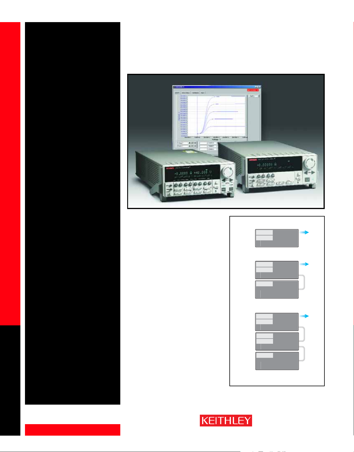
System scalability
without a mainframe
Series 2600 instruments incorporate an innovative technology that makes it possible to create
multi-channel I-V test systems economically, but
without sacrificing test throughput. TSP-Link is a
high speed system expansion interface, which
test system builders can use to connect multiple
Master
Master
TSP-Link makes it easy to scale the system's
channel count to match the application.
2 Channel System
SMU A
SMU B
2602
3 Channel System
SMU A
SMU B
2602
SMU C
Slave
2601
16+ Channel System
SMU A
SMU B
2602
SMU C
Slave
SMU D
2602
Slave
SMU E
2601
GPIB
TSP-Link In
TSP-Link Out
GPIB
TSP-Link In
TSP-Link Out
GPIB
TSP-Link In
TSP-Link Out
GPIB
TSP-Link In
TSP-Link Out
GPIB
TSP-Link In
TSP-Link Out
GPIB
TSP-Link In
TSP-Link Out
•
•
•
To PC
To PC
To PC
1.888.KEITHLEY (U.S. only)
SOURCE AND MEASURE
www.keithley.com
A GREATER MEASURE OF CONFIDENCE
Page 2

Series 2600 System SourceMeter
Multi-Channel I-V Test Solutions
Series 2600 instruments in a master/slave configuration. Once connected, all the Series 2600 instru-
Ordering Information
2601 Single-channel System
2602 Dual-channel System
2611 Single-channel System
2612 Dual-channel System
Accessories Supplied
2600-IAC Safety Interlock Adapter
Connector (one supplied with 2611/2612)
Test Script Builder software
LabTracer Software (downloadable)
IVI/VISA drivers for Visual Basic, VC/C++,
LabVIEW, TestPoint, and LabWindows™/CVI
Mating screw terminal connectors with
strain relief and covers (2600-Kit)
TSP-Link cable (CA-180-3A)
Factory and custom TSP test scripts
The Test Script Processor is programmed
with a simple BASIC-style programming
language that runs in real time on the
instrument. Keithley provides built-in test
scripts for:
• Sweeping
• Pulsing
• Waveform generation
• Common component tests like binary
search, V
current/voltage)
A number of test scripts are included in
the instrument, while others can be downloaded at no charge from www.keithley.
com. These pre-written factory test scripts
can be used as provided or easily customized for a given application, so production
users can get their systems up and running faster than ever before.
Users can also create custom test scripts
in several different ways, including a programming tool called Test Script Builder.
Custom scripts can be downloaded from
the PC to the master SourceMeter unit
and saved in non-volatile memory. All four
models provide 16 megabytes of nonvolatile memory for storing up to 50,000
lines of TSP code and more than 100,000
readings.
SourceMeter Instrument
(High Current)
SourceMeter Instrument
(High Current)
SourceMeter Instrument
(200V)
SourceMeter Instrument
(200V)
, VTH, LIV (light intensity/
F
ments in a system can be programmed and operated under the control of the master unit, just as if
they were housed in the same chassis. By eliminating the need for a chassis/mainframe, the TSP-Link
provides virtually unlimited flexibility to scale a test system’s channel count up or down as the application requires, while ensuring seamless integration.
New capabilities for increasing test speed and lowering test cost
The Test Script Processor (TSP)
Any Series 2600-based system can run high speed, embedded test scripts on the master unit’s Test
Script Processor (TSP), the other major new technology on which the Series 2600 is based. The test
sequence is processed and run on the embedded computer in the instrument, rather than from an
external PC controller, so delays due to GPIB traffic congestion are eliminated. TSP test scripts allow
throughput gains of up to 10× over equivalent PC-based programs controlling the same instruments
via GPIB. TSP test scripts can be loaded and run from the front panel or over the system’s GPIB interface. A single TSP test script, running on the master unit, can control all the SourceMeter channels in
the system and acquire data from any Series 2600 instrument connected to the TSP-Link, which supports connections for up to 64 Series 2600 instruments.
TSP for advanced automation
A Series 2600-based system can stand alone as a complete measurement and automation solution for
semiconductor device or component testing, with the master unit controlling sourcing, measuring,
pass/fail decisions, test sequence flow control, binning, and the component handler or prober. In
contrast with existing embedded test sequencers for instrumentation, the TSP test scripts offer far
greater programming flexibility, including support for:
• Instr ument command queuing
• Modular subroutines with passable parameters
• Pass/fail and limit testing
• A wide range of math operations
• Flexible branching and looping capability
• Flexible external triggering
• Intelligent digital I/O read and write capability
• RS-232 communication
ACCESSORIES AVAILABLE
CABLES AND CONNECTORS
2600-BAN Banana Test Leads/Adapter Cable. For a single
Series 2600 SMU channel
2600-KIT Extra screw terminal connector, strain relief, and
cover for a single SourceMeter channel (one
supplied with 2601/2611, two with 2602/2612)
2600-TRIAX Triax Adapter. For a single Series 2600 Source-
Meter (two needed for use with 2602/2612)
7078-TRX-* 3-Slot, Low Noise Triax Cable. For use with
2600-TRIAX Adapter
8606 High Performance Modular Probe Kit. For use
with 2600-BAN
SC-200 Shielded Twisted Pair Cable. Recommended for
general-purpose use with Series 2600 System
SourceMeter instruments
2600-IAC Safety Interlock Adapter Connector (one supplied
with 2611/2612)
DIGITAL I/O, TRIGGER LINK, AND TPS-LINK
2600-TLINK Digital I/O to TLINK Adapter Cable, 1m
CA-126-1 Digital I/O and Trigger Cable, 1.5m
CA-180-3A CAT5 Crossover Cable for TSP-Link (one supplied)
Scalable, integrated source and measure solutions
GPIB INTERFACES AND CABLES
7007-1 Double Shielded GPIB Cable, 1m (3.3 ft.)
7007-2 Double Shielded GPIB Cable, 2m (6.6 ft.)
KPCI-488LP IEEE-488 Interface/Controller for the PCI Bus
KPXI-488 IEEE-488 Interface Board for the PXI Bus
KUSB-488A IEEE-488 USB-to-GPIB Interface Adapter
SWITCHING
7002-HD High Density Switch Mainframe
7002-HD-MTX1 Differential 6×32 Matrix Card
7002-HD-MUX1 Differential Quad 1×40 Multiplexer Card
RACK MOUNT KITS
4299-1 Single Rack Mount Kit with front and rear support
4299-2 Dual Rack Mount Kit with front and rear support
SOFTWARE
LabTracer™ 2.0 Curve Tracing Software (downloadable)
EXTENDED WARRANTIES
2601-EW 1 Year Extended Warranty for Model 2601
2602-EW 1 Year Extended Warranty for Model 2602
2611-EW 1 Year Extended Warranty for Model 2611
2612-EW 1 Year Extended Warranty for Model 2612
1.888.KEITHLEY (U.S. only)
www.keithley.com
SOURCE AND MEASURE
A GREATER MEASURE OF CONFIDENCE
Page 3
Series 2600
FeedbackSource
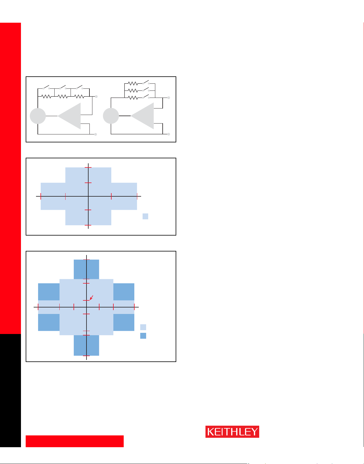
Series vs. parallel ranging topologies
+3A
+1A
+6V–6V
–1A
–3A
Models 2601 and 2602 I-V capability
Scalable, integrated source and measure solutions
+10A
+1.5A
+1A
+0.1A
–5V +5V
+20V–20V
System SourceMeter
Multi-Channel I-V Test Solutions
Third-generation SMU design ensures faster test times
The Series 2600's new SMU design enhances test speed in several ways.
For example, while earlier designs used a parallel current ranging topology, the Series 2600 uses a series ranging topology (patent pending), which
provides faster and smoother range changes and outputs that settle more
FeedbackSource
+40V–40V
DC
+200V–200V
quickly. It also allows the current output limit to be programmed independently of the measurement current range for fast charging of capacitive
loads and more intuitive operation during bench use.
Each Series 2600 SourceMeter channel offers a highly flexible, fourquadrant source coupled with precision voltage and current meters/
limiters. Each channel can be configured as a:
• Precision power supply (up to 200V and 3A DC/10A pulsed output with
1pA readback resolution)
• True current source
• DMM (DCV, DCI, ohms, power, with 5
1
⁄2-digit resolution)
• Power V or I pulse generator (Pulse width: 200µs and longer—source
and measure)
• Power V or I waveform generator (20-point sine wave up to 400Hz in a
TSP test script)
• Electronic load (with sink mode capability)
High speed and precision A/Ds with simultaneous source-readback
All Series 2600 instruments provide four-quadrant operation and can be
connected in series or in parallel to extend their dynamic range. In the
first and third quadrants, they operate as a source, delivering power to a
load. In the second and fourth quadrants, they operate as a sink, dissipating power internally. They measure voltage and current simultaneously
with up to 5
1
⁄2-digit resolution, and they display voltage, current, resist-
ance, or power readings.
Two analog-to-digital converters per channel (one for I, one for V) can run
simultaneously, providing precise source-readback without sacrificing test
throughput. These A/D converters offer the flexibility of programmable
integration rates, allowing the user to optimize for either high speed
(>10,000 rdgs/s at 0.001 NPLC setting) or for high resolution (up to 24
bits at 10 NPLC setting) to make high accuracy measurements.
Models 2611 and 2612 I-V capability
1.888.KEITHLEY (U.S. only)
SOURCE AND MEASURE
www.keithley.com
–0.1A
–1A
–1.5A
–10A
Digital I/O Interface
A back panel port on every Series 2600 instrument provides 14 bits of uni-
DC
Pulse Mode,
duty cycle
limited
versal digital I/O to link the instrument to a variety of popular handlers for
sorting and binning components after testing. These I/O lines are also
backward-compatible with Keithley’s earlier Trigger Link instrument triggering technology. These lines simplify integrating Series 2600 instr uments
into systems that employ other external instrumentation, including Series
2400 SourceMeter instruments, Series 7000 switch mainframes, and Series
2700 Integra data acquisition/multimeter systems.
Built-in Contact Check Function
The Contact Check function makes it simple to verify good connections
quickly and easily before an automated test sequence begins. This eliminates measurement errors and false product failures associated with contact fatigue, breakage, contamination, loose or broken connection, relay
failures, etc.
A GREATER MEASURE OF CONFIDENCE
Page 4
Series 2600
System SourceMeter
Multi-Channel I-V Test Solutions
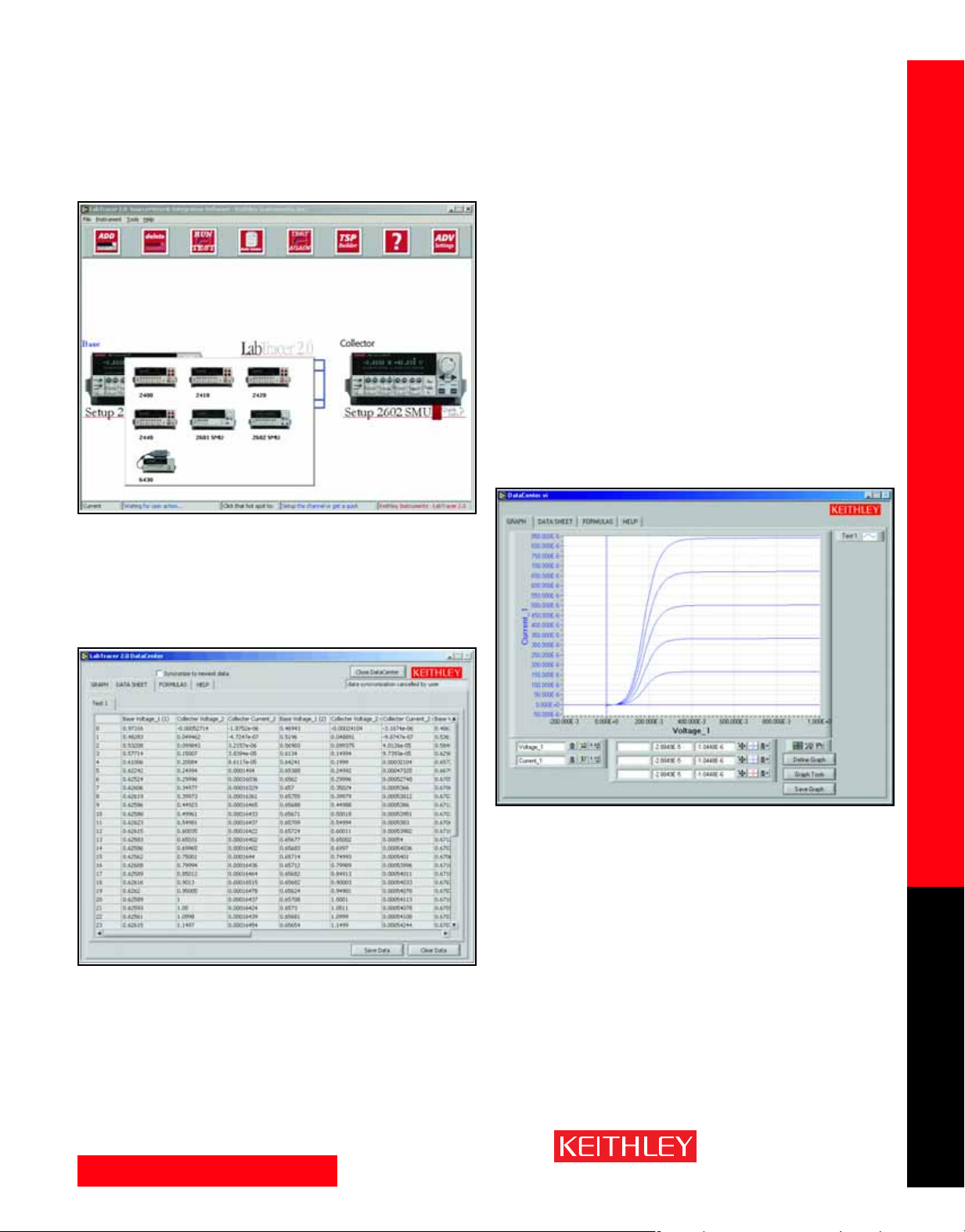
Graphical instrument setup. LabTracer 2.0 supports up to eight Series
2600 SourceMeter channels. Model 2400 and Model 2410 SourceMeter
instruments are also supported for extended voltage capability. Dropdown menus in LabTracer 2.0’s instrument setup window allow configuring any channel of a SourceMeter instrument for fixed point or
sweeping operation. Once the instrument is configured, a single key
press is all it takes to execute a test.
Spanning I-V test applications
from R&D to functional test
The Series 2600 SourceMeter Instruments provide simple-to-use yet powerful solutions for R&D testing. At the same time, they offer the speed and
reliability needed for volume production testing.
High power and simplicity for R&D applications
In R&D and device characterization environments, Series 2600 instruments
offer high testing versatility for both interactive and automated testing. The
free downloadable LabTracer 2.0 software allows users to configure and
control up to eight Series 2600 or 2400 SourceMeter channels quickly and
easily for curve tracing or device characterization. It provides a simple
graphical user interface for setup, control, data acquisition, and graphing
of DUT data from SourceMeter instruments. When used together,
LabTracer and SourceMeter instruments offer lab users a powerful, easy-touse, and economical alternative to chassis-based solutions.
Once a test is complete, data is displayed in the spreadsheet panel and
graphing panel. Measurement data can be manipulated in the spreadsheet by applying a formula to the results. For more detailed analysis,
data can also be exported to Microsoft
paste.
®
Excel with a simple cut and
Scalable, integrated source and measure solutions
1.888.KEITHLEY (U.S. only)
www.keithley.com
SOURCE AND MEASURE
A GREATER MEASURE OF CONFIDENCE
Page 5

Series 2600
System SourceMeter
Multi-Channel I-V Test Solutions
TYPICAL APPLICATIONS
• I-V functional test and characterization of a wide range of
devices, including:
- Discrete and passive components
- Two-leaded – Resistors, disk drive heads, metal oxide
varistors (MOVs), diodes, zener diodes, sensors,
capacitors, thermistors
- Three-leaded – Small signal bipolar junction transistors
(BJTs), field-effect transistors (FETs), and more
- Parallel test – Two- and three-leaded component arrays
- Simple ICs – Optos, drivers, switches, sensors
• Integrated devices – Small Scale Integrated (SSI) and
Large Scale Integrated (LSI).
- Analog ICs
- Radio frequency integrated circuits (RFICs)
- Application specific integrated circuits (ASICs)
- System on a chip (SOC) devices
• Optoelectronic devices such as light-emitting diodes (LEDs),
laser diodes, high brightness LEDs (HBLEDs), vertical cavity
surface-emitting lasers (VCSELs), displays
• R&D and device characterization of these types
of devices
Scalable, integrated source and measure solutions
Dramatic throughput improvements for production test
Series 2600 instruments help component manufacturers improve their test
throughput dramatically, as well as provide test solutions that can handle
today’s devices, which often have higher pin counts and more analog circuitry than earlier designs. In the past, manufacturers have been forced by
the lack of optimized test solutions for multi-channel source-measure
applications to choose between bulky, expensive mainframe-based systems,
slow instrument-based systems employing PC control, or fast instrumentbased systems that require complex development. The Series 2600 offers:
• The highest density available in any SMU-based system to address
growing pin counts.
• The industry’s fastest throughput, which helps reduce the cost of test.
The speed of the onboard processor and TSP test scripts, combined
with the tight triggering synchronization offered by the TSP-Link bus,
makes high speed parallel testing practical.
• A lower capital investment. By eliminating the need for a mainframe/
chassis, they allow test engineers to configure a readily scalable system
at a significantly lower cost per channel than other solutions.
Test Script Builder software
Test Script Builder is a free software tool that is provided with all Series
2600 SourceMeter instruments to help users create, modify, debug, and
store TSP test scripts. It provides a project/file manager window to store
and organize test scripts, a text-sensitive program editor (like Visual Basic)
to create and modify test TSP code, and an immediate instrument control
window to send GPIB commands and receive data from the instrument.
The immediate window allows viewing the output of a given test script and
simplifies debugging.
1.888.KEITHLEY (U.S. only)
SOURCE AND MEASURE
www.keithley.com
Store and
organize
test scripts
in the file
manager
window.
A GREATER MEASURE OF CONFIDENCE
Create and modify test
TSP code in the context
sensitive editor window.
The immediate window
displays test script output
and assists in debugging.
Page 6

2601
System SourceMeter
2602
Multi-Channel I-V Test Solutions
SPECIFICATION CONDITIONS
This document contains specifications and supplemental information for the Models 2601 and 2602.
Specifications are the standards against which the Models 2601 and 2602 are tested. Upon leaving the
factory the 2601 and 2602 meet these specifications. Supplemental and typical values are nonwarranted, apply at 23°C, and are provided solely as useful information.
The source and measurement accuracies are specified at the SourceMeter CHANNEL A (2601 and
2602) or SourceMeter CHANNEL B (2602) terminals under the following conditions:
1. 23°C ± 5°C, <70% relative humidity.
2. After 2 hour warm-up.
3. Speed normal (1 NPLC).
4. A/D auto-zero enabled.
5. Remote sense operation or properly zeroed local operation.
6. Calibration period = 1 year.
SOURCE SPECIFICATIONS
VOLTAGE PROGRAMMING ACCURACY
RANGE
100.000 mV 5µV 0.02% + 250 µV 20 µV
1.00000 V 50 µV 0.02% + 400 µV 50 µV
6.00000 V 50 µV 0.02% + 1.8 mV 100 µV
40.0000 V 500 µV 0.02% + 12 mV 500 µV
TEMPERATURE COEFFICIENT (0°–18°C & 28°–50°C): ±(0.15 × accuracy specification)/°C.
MAXIMUM OUTPUT POWER AND SOURCE/SINK LIMITS
@ ±1.0A, ±6.06V @ ±3.0A, four quadrant source or sink operation.
VOLTAGE REGULATION: Line: 0.01% of range. Load: ±(0.01% of range + 100µV).
NOISE 10Hz–20MHz (peak-peak): 25mV typical into a resistive load.
CURRENT LIMIT/COMPLIANCE
value is 10nA. Accuracy same as current source.
OVERSHOOT: <±(0.1% + 10mV) typical (step size = 10% to 90% of range, resistive load, maximum
current limit/compliance).
GUARD OFFSET VOLTAGE: <10mV typical (Iout ≤ 100mA).
PROGRAMMING
RESOLUTION
3
: Bipolar current limit (compliance) set with single value. Minimum
CURRENT PROGRAMMING ACCURACY
RANGE
100.000 nA 1 pA 0.06% + 100 pA 5 pA
1.00000 µA 10 pA 0.03% + 600 pA 25 pA
10.0000 µA 100 pA 0.03% + 2 nA 50 pA
100.000 µA 1 nA 0.03% + 30 nA 3 nA
1.00000 mA 10 nA 0.03% + 200 nA 5 nA
10.0000 mA 100 nA 0.03% + 3 µA 200 nA
100.000 mA 1 µA 0.03% + 20 µA 500 nA
1.00000 A
3.00000 A
TEMPERATURE COEFFICIENT (0°–18°C & 28°–50°C): ±(0.15 × accuracy specification)/°C.
MAXIMUM OUTPUT POWER AND SOURCE/SINK LIMITS
@ ±40.0V, ±3.03A @ ±6.0V, four quadrant source or sink operation.
CURRENT REGULATION: Line: 0.01% of range. Load: ±(0.01% of range + 100pA).
VOLTAGE LIMIT/COMPLIANCE
Minimum value is 10mV. Accuracy same as voltage source.
OVERSHOOT:<0.1% typical (step size = 10% to 90% of range, resistive load; see CURRENT SOURCE
OUTPUT SETTLING TIME for additional test conditions).
PROGRAMMING
RESOLUTION
2
2
10 µA 0.05% + 900 µ A 60 µA
10 µA 0.06% + 1.5 mA 150 µA
4
: Bipolar voltage limit (compliance) set with a single value.
1
ACCURACY (1 Year)
23°C ±5°C
±(% rdg. + volts)
2
: 40.4W per channel maximum. ±40.4V
ACCURACY (1 Year)
23°C ±5°C
±(% rdg. + amps)
2
: 40.4W per channel maximum. ±1.01A
TYPICAL NOISE
(peak-peak)
0.1Hz–10Hz
TYPICAL NOISE
(peak-peak)
0.1Hz–10Hz
ADDITIONAL SOURCE SPECIFICATIONS
TRANSIENT RESPONSE TIME: <70µs for the output to recover to 0.1% for a 10% to 90% step
change in load.
VOLTAGE SOURCE OUTPUT SETTLING TIME: Time required to reach 0.1% of final value, when
changing from 10% to 90% of range, after source level command is processed on a fixed range.
100mV, 1V R anges: <50µs typical.
6V Range: <100µs typical.
40V Range: <150µs typical.
CURRENT SOURCE OUTPUT SETTLING TIME: Time required to reach 0.1% of final value, when
changing from 10% to 90% of range, after source level command is processed on a fixed range. Values
below for Iout · Rload = 2V unless noted.
3A–10mA Ranges: <80µs typical (current less than 2.5A, Rload >1.5Ω).
1mA Range: <100µs typical.
100µA Range: <150µs typical.
10µA Range: <500µs typical.
1µA Range: <2.5ms typical.
100nA Range: <25ms typical.
DC FLOATING VOLTAGE: Output can be floated up to ±250VDC from chassis ground.
REMOTE SENSE OPERATING RANGE
Maximum voltage between HI and SENSE HI = 3V.
Maximum voltage between LO and SENSE LO = 3V.
VOLTAGE OUTPUT HEADROOM:
40V Range: Max. output voltage = 42V – total voltage drop across source leads (maximum 1Ω per
source lead).
6V Range: Max. output voltage = 8V – total voltage drop across source leads.
OVER TEMPERATURE PROTECTION: Internally sensed temperature overload puts unit in
standby mode.
VOLTAGE SOURCE RANGE CHANGE OVERSHOOT: Overshoot into a 100kΩ load, 20MHz BW,
300mV typical.
CURRENT SOURCE RANGE CHANGE OVERSHOOT: <5% + 300mV/Rload of larger range typical.
(See CURRENT SOURCE OUTPUT SETTLING TIME for additional test conditions.)
5
1
:
NOTES
1. Add 50µV to source accuracy specifications per volt of HI lead drop.
2. Full power source operation regardless of load to 30°C ambient. Above 30°C and/or power sink operation, refer to
Section 8 – Operating Boundaries in the Series 2600 Reference Manual for additional power derating information.
3. For sink mode operation (quadrants II and IV), add 12% of limit range and ±0.02% of limit setting to corresponding
current limit accuracy specifications. For 1A range add an additional 40mA of uncertainty.
4. For sink mode operation (quadrants II and IV), add 10% of compliance range and ±0.02% of limit setting to corresponding voltage source specification. For 100mV range add an additional 60mV of uncertainty.
5. Add 150µs when measuring on the 1A range.
Series 2600 specifications
1.888.KEITHLEY (U.S. only)
www.keithley.com
SOURCE AND MEASURE
A GREATER MEASURE OF CONFIDENCE
Page 7

2601
System SourceMeter
2602
Multi-Channel I-V Test Solutions
METER SPECIFICATIONS
VOLTAGE MEASUREMENT ACCURACY
RANGE
100.000 mV 1 µV
1.00000 V 10 µV
6.00000 V 10 µV
40.0000 V 100 µV
TEMPERATURE COEFFICIENT (0°–18°C & 28°–50°C): ±(0.15 × accuracy specification)/°C.
DISPLAY
RESOLUTION
3
CURRENT MEASUREMENT ACCURACY
RANGE
100.000 nA 1 pA <1 mV 0.05 % + 100 pA
1.00000 µA 10 pA <1 mV 0.025% + 300 pA
10.0000 µA 100 pA <1 mV 0.025% + 1.5 nA
100.000 µA 1 nA <1 mV 0.02 % + 25 nA
1.00000 mA 10 nA <1 mV 0.02 % + 200 nA
10.0000 mA 100 nA <1 mV 0.02 % + 2.5 µ A
100.000 mA 1 µA <1 mV 0.02 % + 20 µA
1.00000 A 10 µA <1 mV 0.03 % + 1.5 mA
Series 2600 specifications
3.00000 A 10 µA <1 mV 0.05 % + 3.5 mA
TEMPERATURE COEFFICIENT (0°–18°C & 28°–50°C): ±(0.15 × accuracy specification)/°C.
CONTACT CHECK
SPEED
FAST 1 (1.2) ms 5% + 10
MEDIUM 4 (5) ms 5% + 1
SLOW 36 (42) ms 5% + 0.3
DISPLAY
RESOLUTION
4
MAXIMUM MEASUREMENT
TIME TO MEMORY
FOR 60Hz (50Hz)
3
ADDITIONAL METER SPECIFICATIONS
LOAD IMPEDANCE: Stable into 10,000pF typical.
COMMON MODE VOLTAGE: 250VDC.
COMMON MODE ISOLATION: >1GΩ, <4500pF.
OVERRANGE: 101% of source range, 102% of measure range.
MAXIMUM SENSE LEAD RESISTANCE:1kΩ for rated accuracy.
SENSE INPUT IMPEDANCE: >10GΩ.
NOTES
1. Add 50µV to source accuracy specifications per volt of HI lead drop.
2. Four-wire remote sense only.
3. Applies when in single channel display mode.
4. Includes measurement of SENSE HI to HI and SENSE LO to LO contact resistances.
1
INPUT
RESISTANCE
>10 GΩ
>10 GΩ
>10 GΩ
>10 GΩ
VOLTAGE
BURDEN
4
ACCURACY (1 Year)
±(% rdg. + volts)
0.015% + 150 µV
0.015% + 200 µV
0.015% + 1 mV
0.015% + 8 mV
ACCURACY (1 Year)
2
±(% rdg. + amps)
ACCURACY (1 Year)
23°C ±5°C
±(%rdg. + ohms)
23°C ±5°C
23°C ±5°C
GENERAL
HOST INTERFACES: Computer control interfaces.
IEEE-488: IEEE-488.1 compliant. Supports IEEE-488.2 common commands and status model
topology.
RS-232: Baud rates from 300 bps to 115200 bps. Programmable number of data bits, parity
type, and flow control (RTS/CTS hardware or none). When not programmed as the active
host interface, the SourceMeter can use the RS-232 interface to control other
instrumentation.
EXPANSION INTERFACE: The TSP-Link expansion interface allows TSP enabled instruments to
trigger and communicate with each other.
Cable Type: Category 5e or higher LAN crossover cable.
Length: 3 meters maximum between each TSP enabled instrument.
DIGITAL I/O INTERFACE:
Connector: 25-pin female D.
Input/Output Pins: 14 open drain I/O bits.
Absolute Maximum Input Voltage:5.25V.
Absolute Minimum Input Voltage:–0.25V.
Maximum Logic Low Input Voltage: 0.7V, +850µA max.
Minimum Logic High Input Voltage:2.1V, +570µA.
Maximum Source Current (flowing out of Digital I/O bit): +960µA.
Maximum Sink Current @ Maximum Logic Low Voltage (0.7V): –5.0mA.
Absolute Maximum Sink Current (flowing into Digital I/O pin): –11mA.
5V Power Supply Pin: Limited to 600mA, solid state fuse protected.
600mA
Solid State
+5V Pin
(on DIGITAL I/O
connector)
Digital I/O Pin
(on DIGITAL I/O
connector)
GND Pin
(on DIGITAL I/O
connector)
Output Enable Pin: Active high input pulled down internally to ground with 10kΩ resistor.
When the Output Enable input function has been activated, each SourceMeter channel will
not turn on unless the Output Enable pin is driven to >2.1V (nominal current = 2.1V /
10kΩ = 210µA).
POWER SUPPLY: 100V to 240VAC, 50–60Hz (manual setting), 240VAmax.
COOLING: Forced air. Side intake and rear exhaust. One side must be unobstructed when rack
mounted.
WARRANTY: 1 year.
EMC: Conforms to European Union Directive 89/336/EEC, EN 61326-1.
SAFETY: Conforms to European Union Directive 73/23/EEC, EN 61010-1, and UL 61010-1.
DIMENSIONS: 89mm high × 213mm wide × 460mm deep (3
Configuration (with handle & feet): 104mm high × 238mm wide × 460mm deep (4
3
⁄8in × 171⁄2in).
9
WEIGHT: 2601:4.75kg (10.4 lbs). 2602: 5.50kg (12.0 lbs).
ENVIRONMENT: For indoor use only.
Altitude: Maximum 2000 meters above sea level.
Operating: 0°–50°C, 70% R.H. up to 35°C. Derate 3% R.H./°C, 35°–50°C.
Storage: –25°C to 65°C.
Fuse
100Ω
Rear Panel
5.1kΩ
+5VDC
Read by
firmware
Written by
firmware
1
⁄2in × 83⁄8in × 171⁄2in). Bench
1
⁄8in ×
1.888.KEITHLEY (U.S. only)
SOURCE AND MEASURE
www.keithley.com
A GREATER MEASURE OF CONFIDENCE
Page 8

2611
+1.5A
+10A
–10A
–1A
+1A
+0.1A
–0.1A
–1.5A
+200V+5V
–5V
+20V–20V 0V
0A
2
2
2
2
4
4
+180V
–180V–200V
1
3
3
3
3
System SourceMeter
2612
SPECIFICATION CONDITIONS
This document contains specifications and supplemental information for the Models 2611 and 2612.
Specifications are the standards against which the Models 2611 and 2612 are tested. Upon leaving the
factory the 2611 and 2612 meet these specifications. Supplemental and typical values are nonwarranted, apply at 23°C, and are provided solely as useful information.
The source and measurement accuracies are specified at the SourceMeter CHANNEL A (2611 and
2612) or SourceMeter CHANNEL B (2612) terminals under the following conditions:
1. 23°C ± 5°C, <70% relative humidity.
2. After 2 hour warm-up.
3. Speed normal (1 NPLC).
4. A/D auto-zero enabled.
5. Remote sense operation or properly zeroed local sense operation.
6. Calibration period = 1 year.
SOURCE SPECIFICATIONS
VOLTAGE PROGRAMMING ACCURACY
RANGE
200.000 mV 5 µV 0.02% + 375 µV 20 µV
2.00000 V 50 µV 0.02% + 600 µV 50 µV
20.0000 V 500 µV 0.02% + 5 mV 300 µV
200.000 V 5mV 0.02% + 50 mV 2mV
TEMPERATURE COEFFICIENT (0°–18°C & 28°–50°C): ±(0.15 × accuracy specification)/°C.
MAXIMUM OUTPUT POWER AND SOURCE/SINK LIMITS
±20.2V @ ±1.515A, ±202V @ ±101mA, four quadrant source or sink operation.
VOLTAGE REGULATION: Line: 0.01% of range. Load: ±(0.01% of range + 100µV).
NOISE 10Hz–20MHz: <5mV RMS typical, 20V range, 1A limit.
CURRENT LIMIT/COMPLIANCE
value is 10nA. Accuracy same as current source.
OVERSHOOT: <±(0.1% + 10mV) typical (step size = 10% to 90% of range, resistive load, maximum
current limit/compliance).
GUARD OFFSET VOLTAGE: <4mV (current ≤10mA).
PROGRAMMING
RESOLUTION
3
: Bipolar current limit (compliance) set with single value. Minimum
CURRENT PROGRAMMING ACCURACY
RANGE
100.000 nA 2 pA 0.06% + 100 pA 5 pA
1.00000 µA 20 pA 0.03% + 800 pA 25 pA
10.0000 µA 200 pA 0.03% + 5 nA 60 pA
100.000 µA 2 nA 0.03% + 60 nA 3 nA
1.00000 mA 20 nA 0.03% + 300 nA 6 nA
10.0000 mA 200 nA 0.03% + 6 µ A 200 nA
100.000 mA 2 µA 0.03% + 30 µA 600 nA
1.00000 A
1.50000 A
10.0000 A
TEMPERATURE COEFFICIENT (0°–18°C & 28°–50°C): ±(0.15 × accuracy specification)/°C.
MAXIMUM OUTPUT POWER AND SOURCE/SINK LIMITS
±1.515A @ ±20.2V, ±101mA @ ±202V, four quadrant source or sink operation.
CURRENT REGULATION: Line: 0.01% of range. Load: ±(0.01% of range + 100pA).
VOLTAGE LIMIT/COMPLIANCE
Minimum value is 10mV. Accuracy same as voltage source.
OVERSHOOT:<0.1% typical (step size = 10% to 90% of range, resistive load; see CURRENT SOURCE
OUTPUT SETTLING TIME for additional test conditions).
1.888.KEITHLEY (U.S. only)
PROGRAMMING
RESOLUTION
2
2
2, 5
20 µA 0.05% + 1.8 mA 70 µA
50 µA 0.06% + 4 mA 150 µ A
200 µA 0.5 % + 40 mA
4
: Bipolar voltage limit (compliance) set with a single value.
ACCURACY (1 Year)
23°C ±5°C
±(% rdg. + volts)
ACCURACY (1 Year)
23°C ±5°C
±(% rdg. + amps)
Multi-Channel I-V Test Solutions
ADDITIONAL SOURCE SPECIFICATIONS
TRANSIENT RESPONSE TIME: <70µs for the output to recover to 0.1% for a 10% to 90% step
change in load.
VOLTAGE SOURCE OUTPUT SETTLING TIME: Time required to reach 0.1% of final value after
source level command is processed on a fixed range.
200mV, 2V R anges: <50µs typical. 20V Range: <100µs typical. 200V Range: <700µs typical.
CURRENT SOURCE OUTPUT SETTLING TIME: Time required to reach 0.1% of final value after source
level command is processed on a fixed range. Values below for Iout · Rload = 2V unless noted.
1.5A–1A Ranges: <120µs typical (Rload >6Ω).
100mA–10mA Ranges: <80µs typical.
1mA Range: <100µs typical.
100µA Range: <150µs typical.
1
NOISE
(peak-peak)
0.1Hz–10Hz
2
: 30.603W per channel maximum.
6
NOISE
(peak-peak)
0.1Hz–10Hz
2
: 30.603W per channel maximum.
DC FLOATING VOLTAGE: Output can be floated up to ±250VDC from chassis ground.
REMOTE SENSE OPERATING RANGE
VOLTAGE OUTPUT HEADROOM:
200V Range: Max. output voltage = 202.3V – total voltage drop across source leads (maximum
1Ω per source lead).
20V Range: Max. output voltage = 23.3V – total voltage drop across source leads (maximum
1Ω per source lead).
OVER TEMPERATURE PROTECTION: Internally sensed temperature overload puts unit in
standby mode.
VOLTAGE SOURCE RANGE CHANGE OVERSHOOT: Overshoot into a 100kΩ load, 20MHz BW,
300mV typical.
CURRENT SOURCE RANGE CHANGE OVERSHOOT: <5% + 300mV/Rload + 60nA of larger range
typical. (See CURRENT SOURCE OUTPUT SETTLING TIME for additional test conditions.)
PULSE SPECIFICATIONS
REGION
MINIMUM PROGRAMMABLE PULSE WIDTH8:200µs. NOTE: Minimum pulse width for settled source
at a given I/V output and load can be longer than 200µs. See note 11 for typical settling times.
PULSE WIDTH PROGRAMMING RESOLUTION: 1µs.
PULSE WIDTH PROGRAMMING ACCURACY
TYPICAL PULSE WIDTH JITTER: 50µs.
MAXIMUM CURRENT
1 100 mA @ 200 V DC, no limit 100%
1 1.5 A @ 20 V DC, no limit 100%
2 1 A @ 180 V 8.5 ms 1%
10
3
4 10 A @ 5 V 1 ms 2.2%
1 A @ 200 V 2.2 ms 1%
1
: Maximum voltage between HI and SENSE HI = 3V.
Maximum voltage between LO and SENSE LO = 3V.
LIMIT
10µA Range: <500µs typical.
1µA Range: <2ms typical.
100nA Range: <20ms typical.
MAXIMUM PULSE
WIDTH
8
: ±25µs.
Series 2600 specifications
8
MAXIMUM DUTY
CYCLE
9
SOURCE AND MEASURE
www.keithley.com
A GREATER MEASURE OF CONFIDENCE
Page 9

2611
Pulse Level
Bias Level
Start t
on
Start t
off
90%
10%
t
on
t
off
10%
System SourceMeter
2612
Multi-Channel I-V Test Solutions
SOURCE SPECIFICATIONS (continued)
PULSE SPECIFICATIONS (continued)
NOTES
1. Add 50µV to source accuracy specifications per volt of HI lead drop.
2. Full power source operation regardless of load to 30°C ambient. Above 30°C and/or power sink operation, refer to
Section 8 – Operating Boundaries in the Series 2600 Reference Manual for additional power derating information.
3. For sink mode operation (quadrants II and IV), add 12% of limit range and ±0.02% of limit setting to corresponding current limit accuracy specifications. For 1A range add an additional 40mA of uncertainty.
4. For sink mode operation (quadrants II and IV), add 10% of compliance range and ±0.02% of limit setting to corresponding voltage source specification. For 200mV range add an additional 120mV of uncertainty.
5. 10A range accessible only in pulse mode.
6. Accuracy specifications do not include connector leakage. Derate accuracy by Vout/2E11 per °C when operating
between 18°–28°C. Derate accuracy by Vout/2E11 + (0.15 * Vout/2E11) per °C when operating <18°C and >28°C.
7. 150mV under pulse conditions with compliance set to 1A.
8. Times measured from the start of pulse to the start of off-time; see figure below.
9. Thermally limited in sink mode (quadrants 2 and 4) and ambient temperatures above 30°C. See power equations
in the reference manual for more information.
10. Voltage source operation with 1.5A current limit.
11. Typical performance for minimum settled pulse widths:
Series 2600 specifications
Source Value Load
5 V
20 V
180 V
200V (1.5A limit)
100 mA
1 A
1 A
10 A
Typical tests were performed using remote operation, 4W sense, Keithley 2600-BAN cables and best, fixed measurement range. For more information on pulse scripts, see the Series 2600 Reference Manual.
0.5 Ω
200 Ω
180 Ω
200 Ω
200 Ω
20 Ω
180 Ω
0.5 Ω
Source Settling
(% of range) Min. Pulse Width
1% 300 µs
0.2% 200 µs
0.2% 5ms
0.2% 1.5 ms
1% 200 µs
1% 500 µs
0.2% 5ms
0.5% 300 µs
METER SPECIFICATIONS
VOLTAGE MEASUREMENT ACCURACY
RANGE
200.000 mV 1µV
2.00000 V 10 µV
20.0000 V 100 µV
200.000 V 1mV
TEMPERATURE COEFFICIENT (0°–18°C & 28°–50°C): ±(0.15 × accuracy specification)/°C.
DISPLAY
RESOLUTION
3
CURRENT MEASUREMENT ACCURACY
RANGE
100.000 nA 1 pA <1 mV 0.05 % + 100 pA
1.00000 µA 10 pA <1 mV 0.025% + 500 pA
10.0000 µA 100 pA <1 mV 0.025% + 1.5 nA
100.000 µA 1 nA <1 mV 0.02 % + 25 nA
1.00000 mA 10 nA <1 mV 0.02 % + 200 nA
10.0000 mA 100 nA <1 mV 0.02 % + 2.5 µA
100.000 mA 1 µA <1 mV 0.02 % + 20 µA
1.00000 A 10 µA <1 mV 0.03 % + 1.5 mA
1.50000 A 10 µA <1 mV 0.05 % + 3.5 mA
10.0000 A
TEMPERATURE COEFFICIENT (0°–18°C & 28°–50°C): ±(0.15 × accuracy specification)/°C.
CONTACT CHECK
SPEED
FAST 1 (1.2) ms 5% + 10
MEDIUM 4 (5) ms 5% + 1
SLOW 36 (42) ms 5% + 0.3
DISPLAY
RESOLUTION
5
4
MAXIMUM MEASUREMENT
TIME TO MEMORY
FOR 60Hz (50Hz)
3
100 µA <1 mV 0.4 % + 25 mA
1, 7
INPUT
RESISTANCE
>10 GΩ
>10 GΩ
>10 GΩ
>10 GΩ
6, 7
VOLTAGE
BURDEN
4
ACCURACY (1 Year)
±(% rdg. + volts)
0.015% + 225 µV
0.02 % +350 µV
0.015% + 5 mV
0.015% + 50 mV
ACCURACY (1 Year)
2
±(% rdg. + amps)
ACCURACY (1 Year)
23°C ±5°C
±(%rdg. + ohms)
23°C ±5°C
23°C ±5°C
1.888.KEITHLEY (U.S. only)
SOURCE AND MEASURE
www.keithley.com
ADDITIONAL METER SPECIFICATIONS
LOAD IMPEDANCE: Stable into 10,000pF typical.
COMMON MODE VOLTAGE: 250VDC.
COMMON MODE ISOLATION: >1GΩ, <4500pF.
OVERRANGE: 101% of source range, 102% of measure range.
MAXIMUM SENSE LEAD RESISTANCE:1kΩ for rated accuracy.
SENSE INPUT IMPEDANCE: >10GΩ.
NOTES
1. Add 50µV to source accuracy specifications per volt of HI lead drop.
2. Four-wire remote sense only.
3. Applies when in single channel display mode.
4. Includes measurement of SENSE HI to HI and SENSE LO to LO contact resistances.
5. 10A range accessible only in pulse mode.
6. De-rate accuracy by Vout/2E11 per °C when operating between 18°–28°C. Derate accuracy by Vout/2E11 + (0.15 *
Vout/2E11) per °C when operating <18°C and >28°C.
7. De-rate accuracy specifications for NPLC setting <1 by increasing error term. Add appropriate % of range term using
table below:
NPLC 200mV 2V–200V 100nA 1µA–100mA 1A–1.5A
Setting Range Ranges Range Ranges Ranges
0.1 0.01% 0.01% 0.01% 0.01% 0.01%
0.01 0.08% 0.07% 0.1 % 0.05% 0.05%
0.001 0.8 % 0.6 % 1 % 0.5 % 1.1 %
A GREATER MEASURE OF CONFIDENCE
Page 10

2611
10kΩ
Coil
Resistance
145Ω ±10%
Read by firmware
INTERLOCK Pin
(on DIGITAL I/O
connector)
Rear Panel
Chassis
Ground
To output stage
+220V Supply
–220V Supply
System SourceMeter
2612
Multi-Channel I-V Test Solutions
GENERAL
HOST INTERFACES: Computer control interfaces.
IEEE-488: IEEE-488.1 compliant. Supports IEEE-488.2 common commands and status model topology.
RS-232: Baud rates from 300 bps to 115200 bps. Programmable number of data bits, parity type, and flow control (RTS/CTS hard-
ware or none). When not programmed as the active host interface, the SourceMeter can use the RS-232 interface to control other
instrumentation.
EXPANSION INTERFACE: The TSP-Link expansion interface allows TSP enabled instruments to trigger and communicate with
each other.
Cable Type: Category 5e or higher LAN crossover cable.
Length: 3 meters maximum between each TSP enabled instrument.
DIGITAL I/O INTERFACE (see 2601/02 GENERAL specifications for circuit diagram):
Connector: 25-pin female D.
Input/Output Pins: 14 open drain I/O bits.
Absolute Maximum Input Voltage:5.25V.
Absolute Minimum Input Voltage:–0.25V.
Maximum Logic Low Input Voltage: 0.7V, +850µA max.
Minimum Logic High Input Voltage:2.1V, +570µA.
Maximum Source Current (flowing out of Digital I/O bit): +960µA.
Maximum Sink Current @ Maximum Logic Low Voltage (0.7V): –5.0mA.
Absolute Maximum Sink Current (flowing into Digital I/O pin): –11mA.
5V Power Supply Pin: Limited to 600mA, solid state fuse protected.
Safety Interlock Pin: Active high input. >3.4V @ 24mA (absolute maximum of 6V) must be externally applied to this pin to
insure 200V operation. This signal is pulled down to chassis ground with a 10kΩ resistor. 200V operation will be blocked
when the INTERLOCK signal is <0.4V (absolute minimum of –0.4V). See figure below:
Series 2600 specifications
POWER SUPPLY: 100V to 240VAC, 50–60Hz (manual setting), 240VAmax.
COOLING: Forced air. Side intake and rear exhaust. One side must be unobstructed when rack mounted.
WARRANTY: 1 year.
EMC: Conforms to European Union Directive 89/336/EEC, EN 61326-1.
SAFETY: Conforms to European Union Directive 73/23/EEC, EN 61010-1, and UL 61010-1.
DIMENSIONS: 89mm high × 213mm wide × 460mm deep (3
104mm high × 238mm wide × 460mm deep (4
WEIGHT: 2611:4.75kg (10.4 lbs). 2612: 5.50kg (12.0 lbs).
ENVIRONMENT: For indoor use only.
Altitude: Maximum 2000 meters above sea level.
Operating: 0°–50°C, 70% R.H. up to 35°C. Derate 3% R.H./°C, 35°–50°C.
Storage: –25°C to 65°C.
1.888.KEITHLEY (U.S. only)
www.keithley.com
1
1
⁄2in × 83⁄8in × 171⁄2in). Bench Configuration (with handle & feet):
⁄8in × 93⁄8in × 171⁄2in).
A GREATER MEASURE OF CONFIDENCE
SOURCE AND MEASURE
Page 11

Series 2600
System SourceMeter
Multi-Channel I-V Test Solutions
SPEED SPECIFICATIONS
1
MAXIMUM SWEEP OPERATION RATES (operations per second) FOR 60Hz (50Hz):
A/D CONVERTER
SPEED
0.001 NPLC Internal 10000 (10000) 8000 (8000) 5500 (5500) 3600 (3600) 4900 (4900) 3100 (3100)
0.001 NPLC Digital I/O 2700 (2650) 2100 (2100) 2300 (2300) 1900 (1875) 2200 (2150) 1800 (1775)
0.01 NPLC Internal 4000 (3500) 3600 (3200) 2750 (2700) 2300 (2100) 2800 (2500) 2100 (1975)
0.01 NPLC Digital I/O 1900 (1775) 1600 (1500) 1700 (1600) 1450 (1400) 1600 (1500) 1400 (1325)
0.1 NPLC Internal 565 (475) 555 (470) 540 (450) 510 (440) 535 (455) 505 (430)
0.1 NPLC Digital I/O 490 (420) 470 (405) 470 (410) 450 (390) 470 (400) 450 (390)
1.0 NPLC Internal 59 (49) 59 (49) 58 (49) 58 (48) 58 (49) 58 (48)
1.0 NPLC Digital I/O 58 (48) 58 (48) 58 (48) 57 (48) 57 (48) 57 (48)
TRIGGER ORIGIN
MEASURE
TO MEMORY
MEASURE
TO GPIB
SOURCE MEASURE
TO MEMORY
MAXIMUM SINGLE MEASUREMENT RATES (operations per second) FOR 60Hz (50Hz):
A/D CONVERTER
SPEED
0.001 NPLC Internal 1110 (1000) 880 (880) 840 (840)
0.01 NPLC Internal 950 (900) 780 (760) 730 (710)
0.1 NPLC Internal 390 (345) 355 (320) 340 (305)
1.0 NPLC Internal 57 (48) 56 (47) 56 (47)
MAXIMUM MEASUREMENT RANGE CHANGE RATE: >4500/second typical. When changing to or
Series 2600 specifications
from a range ≥1A, maximum rate is >2000/second typical.
MAXIMUM SOURCE RANGE CHANGE RATE: >400/second, typical.
MAXIMUM SOURCE FUNCTION CHANGE RATE: >500/second, typical.
EXTERNAL TRIGGER INPUT: The Digital I/O interface signals can be configured to behave as trigger
inputs.
Input Latency (time from trigger input to start of measurement or source change):
<150µs, typical.
Input Jitter: <100µs, typical.
COMMAND PROCESSING TIME: Maximum time required for the output to begin to change follow-
ing the receipt of the smux.source.levelv or smux.source.leveli command. <1ms typical.
TRIGGER ORIGIN
MEASURE
TO GPIB
SOURCE MEASURE
TO GPIB
SOURCE MEASURE
PASS/FAIL
TO GPIB
SOURCE MEASURE
TO GPIB
SOURCE MEASURE
PASS/FAIL
TO MEMORY
SOURCE MEASURE
PASS/FAIL
TO GPIB
NOTES
1. See the Speed Specifications Test Conditions Appendix in the Series 2600 Reference Manual for more information
regarding test conditions.
Specifications are subject to change without notice. Rev. B
Model 2601/2611 Rear Panel
1.888.KEITHLEY (U.S. only)
SOURCE AND MEASURE
www.keithley.com
Model 2602/2612 Rear Panel
A GREATER MEASURE OF CONFIDENCE
Page 12

Series 2600
System SourceMeter
Multi-Channel I-V Test Solutions
SUPPLEMENTAL INFORMATION
FRONT PANEL INTERFACE: 2-line vacuum fluorescent display (VFD) with keypad and rotary knob.
Display:
• Show error messages and user defined messages
• Display source and limit settings
• Show current and voltage measurements
• View measurements stored in non-volatile reading buffers
Keypad Operations:
• Change host interface settings
• Save and restore instr ument setups
• Load and r un factor y and user defined test scripts (i.e. sequences) that prompt for input and
send results to the display
• Store measurements into non-volatile reading buffers
PROGRAMMING: Embedded Test Script Processor (TSP) accessible from any host interface. Responds
to individual instrument control commands. Responds to high speed test scripts comprised of
instrument control commands and Test Script Language (TSL) statements (e.g. branching, looping,
math, etc.). Able to execute high speed test scripts stored in memory without host intervention.
Minimum Memory Available: 3 Mbytes (approximately 50,000 lines of TSL code).
Test Script Builder: Integrated Development Environment for building, running, and managing
TSP scripts. Includes an Instrument Console for communicating with any TSP enabled instrument in an interactive manner. Requires:
• VISA (NI-VISA included on CD)
• Microsoft .NET Framework (included on CD)
• Keithley I/O Layer (included on CD)
• Pentium III 800MHz or faster personal computer
• Microsoft Windows 98, NT, 2000, or XP
Drivers: IVI/VISA drivers for VB, VC/C++, LabVIEW, TestPoint, and LabWindows/CVI
READING BUFFERS: Non-volatile storage area(s) reserved for measurement data. Reading buffers are
arrays of measurement elements. Each element can hold the following items:
• Measurement
• Measurement status
• Timestamp
• Source setting (at the time the measurement was taken)
• R ange information
Two reading buffers are reserved for each SourceMeter channel. Reading buffers can be filled using
the front panel STORE key and retrieved using the RECALL key or host interface.
Buffer Size, with timestamp and source setting: >50,000 samples.
Buffer Size, without timestamp and source setting: >100,000 samples.
Battery Backup: Lithium-ion battery backup. 30 days of non-volatile storage @ 23°C, and
>4 hours of charge time. 3 year battery life @ 23°C. 1.5 year battery life @ 50°C.
FACTORY TSPSCRIPTS: See
SYSTEM EXPANSION: The TSP-Link expansion interface allows TSP enabled instr uments to trigger
and communicate with each other. See figure below:
Each SourceMeter has two TSP-Link connectors to facilitate chaining instruments together.
• Once SourceMeter instr uments are interconnected via TSP-Link, a computer can access all of the
resources of each SourceMeter via the host interface of any SourceMeter.
• A maximum of 64 TSP-Link nodes can be interconnected. Each SourceMeter consumes one
TSP-Link node.
TIMER: Free running 47 bit counter with 1MHz clock input. Reset each time instrument powers up.
Rolls over every 4 years.
Timestamp: TIMER value automatically saved when each measurement is triggered.
Resolution: 1µs.
Accuracy: 50ppm.
www.keithley.comfor Keithley-supported application-specific scripts.
Series 2600 specifications
1.888.KEITHLEY (U.S. only)
www.keithley.com
SOURCE AND MEASURE
A GREATER MEASURE OF CONFIDENCE
 Loading...