


Model 2302/2302-PJ/2306/2306-PJ/2306-VS
Battery/Charger Simulator
Quick Results Guide
A GREATER MEASURE OF CONFIDENCE

WARRANTY
Keithley Instruments, Inc. warrants this product to be free from defects in material and workmanship for a
period of 1 year from date of shipment.
Keithley Instruments, Inc. warrants the following items for 90 days from the date of shipment: probes, cables,
rechargeable batteries, diskettes, and documentation.
During the warranty period, we will, at our option, either repair or replace any product that proves to be defective.
To exercise this warranty, write or call your local Keithley representative, or contact Keithley headquarters in
Cleveland, Ohio. You will be given prompt assistance and return instructions. Send the product, transportation
prepaid, to the indicated service facility. Repairs will be made and the product returned, transportation prepaid.
Repaired or replaced products are warranted for the balance of the original warranty period, or at least 90 days.
LIMITATION OF WARRANTY
This warranty does not apply to defects resulting from product modification without Keithley’s express written
consent, or misuse of any product or part. This warranty also does not apply to fuses, software, non-rechargeable
batteries, damage from battery leakage, or problems arising from normal wear or failure to follow instructions.
THIS WARRANTY IS IN LIEU OF ALL OTHER WARRANTIES, EXPRESSED OR IMPLIED, INCLUDING ANY IMPLIED WARRANTY OF MERCHANTABILITY OR FITNESS FOR A PARTICULAR USE.
THE REMEDIES PROVIDED HEREIN ARE BUYER’S SOLE AND EXCLUSIVE REMEDIES.
NEITHER KEITHLEY INSTRUMENTS, INC. NOR ANY OF ITS EMPLOYEES SHALL BE LIABLE FOR
ANY DIRECT, INDIRECT, SPECIAL, INCIDENTAL OR CONSEQUENTIAL DAMAGES ARISING OUT OF
THE USE OF ITS INSTRUMENTS AND SOFTWARE EVEN IF KEITHLEY INSTRUMENTS, INC., HAS
BEEN ADVISED IN ADVANCE OF THE POSSIBILITY OF SUCH DAMAGES. SUCH EXCLUDED DAMAGES SHALL INCLUDE, BUT ARE NOT LIMITED TO: COSTS OF REMOVAL AND INSTALLATION,
LOSSES SUSTAINED AS THE RESULT OF INJURY TO ANY PERSON, OR DAMAGE TO PROPERTY.
Keithley Instruments, Inc.
Sales Offices: BELGIUM:
CHINA:
Yuan Chen Xin Building, Room 705 • 12 Yumin Road, Dewai, Madian • Beijing 100029 • 8610-82251886 • Fax: 8610-82251892
FINLAND:
FRANCE:
GERMANY:
GREAT BRITAIN:
INDIA:
1/5, Eagles Street • Langford Town • Bangalore 560 025 • 080 212 80-27 • Fax: 080 212 80 05
ITALY:
Viale San Gimignano, 38 • 20146 Milano • 02-48 39 16 01 • Fax: 02-48 30 22 74
JAPAN:
New Pier Takeshiba North Tower 13F • 11-1, Kaigan 1-chome • Minato-ku, Tokyo 105-0022 • 81-3-5733-7555 • Fax: 81-3-5733-7556
KOREA:
2FL., URI Building • 2-14 Yangjae-Dong • Seocho-Gu, Seoul 137-888 • 82-2-574-7778 • Fax: 82-2-574-7838
NETHERLANDS:
SWEDEN:
TAIWAN:
28775 Aurora Road • Cleveland, Ohio 44139 • 440-248-0400 • Fax: 440-248-6168
1-888-KEITHLEY (534-8453) • www.keithley.com
Bergensesteenweg 709 • B-1600 Sint-Pieters-Leeuw • 02-363 00 40 • Fax: 02-363 00 64
Halsuantie 2 • 00420 Helsinki, Finland • 09-53 06 65 60 • Fax: 09-53 06 65 65
3, allée des Garays • 91127 Palaiseau Cédex • 01-64 53 20 20 • Fax: 01-60 11 77 26
Landsberger Strasse 65 • 82110 Germering • 089-84 93 07-40 • Fax: 089-84 93 07-34
Unit 2 Commerce Park, Brunel Road • Theale, Berkshire RG7 4AB • 0118 -929 75 00 • Fax: 0118- 929 75 19
Postbus 559 • 4200 AN Gorinchem • 0183-63 53 33 • Fax: 0183-63 08 21
c/o Regus Business Centre • Frosundaviks Allé 15, 4tr • 16970 Solna • 08-50 90 46 00 • Fax: 08-655 26 10
13F-3, NO. 6, Lane 99, Pu-Ding Road, Hsinchu, Taiwan, ROC. • 886-3-572-9077 • Fax: 886-3-572-9031
5/03

Model 2302/2302-PJ/2306/2306-PJ/2306-VS
Battery/Charger Simulator
Quick Results Guide
©1999, Keithley Instruments, Inc.
All rights reserved.
Cleveland, Ohio, U.S.A.
Third Printing, June 2003
Document Number: 2306-903-01 Rev. C

Manual Print History
The print history shown below lists the printing dates of all Revisions and Addenda created
for this manual. The Revision Level letter increases alphabetically as the manual undergoes subsequent updates. Addenda, which are released between Revisions, contain important change information that the user should incorporate immediately into the manual. Addenda are numbered
sequentially. When a new Revision is created, all Addenda associated with the previous Revision
of the manual are incorporated into the new Revision of the manual. Each new Revision includes
a revised copy of this print history page.
Revision A (Document Number 2306-903-01)............................................................. March 1999
Revision B (Document Number 2306-903-01) ................................................................ May 2000
Revision C (Document Number 2306-903-01) ................................................................ June 2003
All Keithley product names are trademarks or registered trademarks of Keithley Instruments, Inc.
Other brand names are trademarks or registered trademarks of their respective holders.

S
afety Precautions
The following safety precautions should be observed before using this product and any associated instrumentation. Although
some instruments and accessories would normally be used with non-hazardous voltages, there are situations where hazardous
conditions may be present.
This product is intended for use by qualified personnel who recognize shock hazards and are familiar with the safety precautions
required to avoid possible injury. Read and follow all installation, operation, and maintenance information carefully before using the product. Refer to the manual for complete product specifications.
If the product is used in a manner not specified, the protection provided by the product may be impaired.
The types of product users are:
Responsible body
ment is operated within its specifications and operating limits, and for ensuring that operators are adequately trained.
Operators
instrument. They must be protected from electric shock and contact with hazardous live circuits.
Maintenance personnel
voltage or replacing consumable materials. Maintenance procedures are described in the manual. The procedures explicitly state
if the operator may perform them. Otherwise, they should be performed only by service personnel.
Service personnel
trained service personnel may perform installation and service procedures.
Keithley products are designed for use with electrical signals that are rated Measurement Category I and Measurement Category
II, as described in the International Electrotechnical Commission (IEC) Standard IEC 60664. Most measurement, control, and
data I/O signals are Measurement Category I and must not be directly connected to mains voltage or to voltage sources with
high transient over-voltages. Measurement Category II connections require protection for high transient over-voltages often
associated with local AC mains connections. Assume all measurement, control, and data I/O connections are for connection to
Category I sources unless otherwise marked or described in the Manual.
Exercise extreme caution when a shock hazard is present. Lethal voltage may be present on cable connector jacks or test fixtures.
The American National Standards Institute (ANSI) states that a shock hazard exists when voltage levels greater than 30V RMS,
42.4V peak, or 60VDC are present.
circuit before measuring.
Operators of this product must be protected from electric shock at all times. The responsible body must ensure that operators
are prevented access and/or insulated from every connection point. In some cases, connections must be exposed to potential
human contact. Product operators in these circumstances must be trained to protect themselves from the risk of electric shock.
If the circuit is capable of operating at or above 1000 volts,
Do not connect switching cards directly to unlimited power circuits. They are intended to be used with impedance limited
sources. NEVER connect switching cards directly to AC mains. When connecting sources to switching cards, install protective
devices to limit fault current and voltage to the card.
Before operating an instrument, make sure the line cord is connected to a properly grounded power receptacle. Inspect the
connecting cables, test leads, and jumpers for possible wear, cracks, or breaks before each use.
When installing equipment where access to the main power cord is restricted, such as rack mounting, a separate main input
power disconnect device must be provided, in close proximity to the equipment and within easy reach of the operator.
For maximum safety, do not touch the product, test cables, or any other instruments while power is applied to the circuit under
test. ALWAYS remove power from the entire test system and discharge any capacitors before: connecting or disconnecting
is the individual or group responsible for the use and maintenance of equipment, for ensuring that the equip-
use the product for its intended function. They must be trained in electrical safety procedures and proper use of the
perform routine procedures on the product to keep it operating properly, for example, setting the line
are trained to work on live circuits, and perform safe installations and repairs of products. Only properly
A good safety practice is to expect that hazardous voltage is present in any unknown
no conductive part of the circuit may be exposed.
5/03

cables or jumpers, installing or removing switching cards, or making internal changes, such as installing or removing jumpers.
Do not touch any object that could provide a current path to the common side of the circuit under test or power line (earth) ground.
Always make measurements with dry hands while standing on a dry, insulated surface capable of withstanding the voltage being
measured.
The instrument and accessories must be used in accordance with its specifications and operating instructions or the safety of the
equipment may be impaired.
Do not exceed the maximum signal levels of the instruments and accessories, as defined in the specifications and operating
information, and as shown on the instrument or test fixture panels, or switching card.
When fuses are used in a product, replace with same type and rating for continued protection against fire hazard.
Chassis connections must only be used as shield connections for measuring circuits, NOT as safety earth ground connections.
If you are using a test fixture, keep the lid closed while power is applied to the device under test. Safe operation requires the use
of a lid interlock.
If a screw is present, connect it to safety earth ground using the wire recommended in the user documentation.
!
The symbol on an instrument indicates that the user should refer to the operating instructions located in the manual.
The symbol on an instrument shows that it can source or measure 1000 volts or more, including the combined effect of
normal and common mode voltages. Use standard safety precautions to avoid personal contact with these voltages.
The symbol indicates a connection terminal to the equipment frame.
The
WARNING
information very carefully before performing the indicated procedure.
The
CAUTION
warranty.
Instrumentation and accessories shall not be connected to humans.
Before performing any maintenance, disconnect the line cord and all test cables.
To maintain protection from electric shock and fire, replacement components in mains circuits, including the power transformer,
test leads, and input jacks, must be purchased from Keithley Instruments. Standard fuses, with applicable national safety
approvals, may be used if the rating and type are the same. Other components that are not safety related may be purchased from
other suppliers as long as they are equivalent to the original component. (Note that selected parts should be purchased only
through Keithley Instruments to maintain accuracy and functionality of the product.) If you are unsure about the applicability
of a replacement component, call a Keithley Instruments office for information.
To clean an instrument, use a damp cloth or mild, water based cleaner. Clean the exterior of the instrument only. Do not apply
cleaner directly to the instrument or allow liquids to enter or spill on the instrument. Products that consist of a circuit board with
no case or chassis (e.g., data acquisition board for installation into a computer) should never require cleaning if handled according to instructions. If the board becomes contaminated and operation is affected, the board should be returned to the factory for
proper cleaning/servicing.
heading in a manual explains dangers that might result in personal injury or death. Always read the associated
heading in a manual explains hazards that could damage the instrument. Such damage may invalidate the

Table of Contents
Introduction ................................................................................... 2
Performance features ..................................................................... 3
Proper connection of the supply to the DUT ................................ 4
Front panel operation .................................................................... 6
Menu controls ........................................................................ 6
Setting the output voltage, current range, and current limit .. 7
Turning supply output ON/OFF ............................................. 7
Actual V and I mode .............................................................. 7
DVM input mode ................................................................. 10
Pulse current mode ............................................................... 10
Long integration mode ......................................................... 18
Advanced features ....................................................................... 22
Simulating battery impedance .............................................. 22
Variable output bandwidth ................................................... 28
External triggering ............................................................... 29
List of Illustrations
Figure 1 Model 2306 front panel.............................................................. 2
Figure 2 Rear panel view of Model 2306 and 2306-PJ............................ 4
Figure 3 Rear panel view of Model 2306-VS .......................................... 5
Figure 4 4-wire remote sense connection of the DUT to the output ........ 5
Figure 5 2-wire local sense connection of the DUT to the output ........... 6
Figure 6 Pulsed waveform...................................................................... 11
Figure 7 Eliminating the effect of a current transient on a
pulse current measurement................................................. 12
Figure 8 Circuit — determining the dynamic voltage and
current characteristics of a DUT ........................................ 15
Figure 9 Pulsed waveform ..................................................................... 18
Figure 10 Battery schematic..................................................................... 22
Figure 11 Actual battery pack terminal voltage during
GSM phone simulation ...................................................... 23
Figure 12 Simulated GSM phone current profile..................................... 24
Figure 13 Electronic resistance of NiCd, NiMH, and
Li ion battery packs............................................................ 25
Figure 14 Effect of variable output impedance control............................ 26
Figure 15 Voltage drop sample (with supplied Li ion battery pack) ....... 27
Figure 16 Voltage drop sample (with Model 2306 and
output impedance set at 0.24Ω) ......................................... 28
Figure 17 Typical trigger sequence.......................................................... 29


Model 2306
Quick Results Guide
NOTE
This quick results guide provides information on five different models of battery or
battery/charger simulators (Models 2302, 2302-PJ, 2306, 2306-PJ, and 2306-VS).
In this guide, references to Model 2306 apply to all of the simulators unless
otherwise noted. Likewise, references to specific models (for example, Model 2306,
2306-PJ, or 2306-VS, or Model 2302 or 2302-PJ) refer only to the models listed.
Since the Model 2302 and 2302-PJ are single channel battery simulators, functions
related to the second channel (i.e., the charger channel) are not available for these
models. Therefore:
• battery and charger channel features contained in this manual apply for
the Models 2306, 2306-PJ, and 2306-VS
• only battery channel features contained in this manual apply for the
Models 2302 and 2302-PJ
References to the Model 2302 also apply to the Model 2302-PJ unless otherwise
noted. Refer to Appendix F of Instruction Manual (2306-901-01) for specific
Model 2302 and 2302-PJ information.
Information contained in this guide applies to all power supply channels (unless
otherwise noted). In this manual, channel 1 refers to the battery channel while
channel 2 refers to the charger channel (2306, 2306-PJ, and 2306-VS features only).
For additional information on any feature discussed in this guide (including
programming examples), refer to the Instruction Manual (part number
2306-901-00).

2 Introduction
Introduction
This guide is designed to familiarize users of the Keithley Model 2306 Dual Channel Battery/
Charger Simulator and Model 2302 Single Channel Battery Simulator with the basic operating
features available from the instrument’s front panel and also the GPIB bus. The sequence of
operating instructions reflects the order in which the instrument would be configured for a
typical application. For each operating mode, an example set of bus commands is provided.
While the SCPI command strings are generic, the exact programming syntax will depend on the
test program language.
Figure 1
Model 2306 front panel
2306 DUAL CHANNEL BATTERY/CHARGER SIMULATOR
POWER
DISPLAY
LOCAL
MENU
ENTER
OPERATE
SET

Performance features
The battery channel, the single output channel of the Model 2302 and channel #1 on the
Model 2306, has several enhanced performance features:
1. The transient response, defined by the voltage recovery time and voltage drop when
subjected to a 1000% load change, is faster. For exact specifications, refer to Appendix A
in the Model 2306 Instruction Manual.
2. Three current trigger ranges for pulsed current and long integration operation as opposed
to a single range on the charger channel, channel #2 (5A). Available trigger ranges for the
5A current range: 100mA, 1A, and 5A. Available trigger ranges for the 500mA current
range (Model 2306-PJ and 2302-PJ): 10mA, 100mA, and 500mA.
3. Variable output impedance on channel #1 (0
fixed output impedance.
Introduction 3
Ω
to 1.00Ω in 0.01Ω steps). Channel #2 has

4 Proper connection of the supply to the DUT
WARNING:
NO INTERNAL OPERATOR SERVICABLE PARTS,SERVICE BY QUALIFIED PERSONNEL ONLY.
WARNING:
NO INTERNAL OPERATOR SERVICABLE PARTS,SERVICE BY QUALIFIED PERSONNEL ONLY.
CAUTION:
FOR CONTINUED PROTECTION AGAINST FIRE HAZARD,REPLACE FUSE WITH SAME TYPE AND RATING.
CAUTION:
FOR CONTINUED PROTECTION AGAINST FIRE HAZARD,REPLACE FUSE WITH SAME TYPE AND RATING.
Proper connection of the supply to the DUT
WARNING
When installing a unit into a test system, make sure the external power
sources do not apply voltage to the power supply in excess of its maximum
limits (see specifications). Failure to do so could result in personal injury or
death.
WARNING
The power cord supplied with the Model 2306 contains a separate ground
for use with grounded outlets. When proper connections are made,
instrument chassis is connected to power line ground through the ground
wire in the power cord. Failure to use a grounded outlet may result in
personal injury or death due to electric shock.
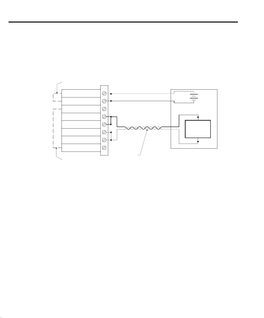
Figure 2 shows a rear panel view of the Models 2306 and 2306-PJ detailing the connector
sockets for the battery channel “OUTPUT #1” and the charger channel “OUTPUT #2.” Figure 3
shows the rear panel of the Model 2306-VS. The Model 2306 does not have an internal local
sense connection. Therefore, the operator must connect the DUT to the supply in either a remote
or local sense configuration as illustrated. For a 4-wire remote sense application, the sense inputs
to the supply must be connected at load as close to the inputs of the load as possible through
twisted pair leads as shown in Figure 4.
Figure 2
Rear panel view of Model 2306 and 2306-PJ
DVM IN
LINE FUSE
SLOWBLOW
2.0A, 250V
LINE RATING
REMOTE
DISPLAY
OPTION
OUTPUT #2
SOURCE SENSE
+++
SOURCE
____
DVM IN
+
MADE IN
U.S.A.
RELAY
CONTROL
24VDC MAX.
OUTPUT #1
SOURCE SENSE
+++
CAT
I
(ENTER IEEE ADDRESS
FROM FRONT PANEL MENU)
DVM IN
SOURCE
____
ISOLATION FROM EARTH: 22 VOLTS MAX.
IEEE-488
+30 VDC MAX.
+
100-120VAC, 200-240VAC
50, 60 HZ 150VA MAX.

Figure 3
WARNING:NO INTERNAL OPERATOR SERVICABLE PARTS,SERVICE BY QUALIFIED PERSONNEL ONLY.
CAUTION:FOR CONTINUED PROTECTION AGAINST FIRE HAZARD,REPLACE FUSE WITH SAME TYPE AND RATING.
Rear panel view of Model 2306-VS
Proper connection of the supply to the DUT 5
NOTE
ISOLATION FROM EARTH: 22 VOLTS MAX.
OUTPUT #1
SOURCE
SOURCE SENSE
____
+++
IN OUT IN OUT
CHANNEL 1 CHANNEL 2
IEEE-488
MADE IN
U.S.A.
The TRIGGER connectors on the rear panel of the Model 2306-VS are associated
TRIGGER
CAT I
DVM IN
+
DVM IN
+30 VDC MAX.
OUTPUT #2
SOURCE SENSE SOURCE
+++
LINE FUSE
SLOWBLOW
2.0A, 250V
LINE RATING
100-120VAC,
200-240VAC
50, 60 HZ
150VA MAX.
____
DVM IN
with the external triggering and voltage stepping capabilities of the unit. See
"External triggering" on page 29 and Section 6 of the Model 2306 Instruction
Manual for details.
Figure 4
4-wire remote sense connection of the DUT to the output
Quick Disconnect
DVM input
Connector
External Test Circuit
DVM +
DVM -
Source -
Source -
Sense -
Sense +
Source +
Source +
+
+
-
DUT
Model 2306
source input/output
NOTE
Twisted pair
DO NOT jumper the sense inputs and supply outputs at the rear of the supply.
DO NOT pass the source and sense leads together in the same twisted pair.
6 Front panel operation
Failure to connect the sense leads in this fashion will
severely
compromise the performance
of Model 2306 with dynamic loads. Figure 5 illustrates the proper connection of the supply to
the DUT using a 2-wire local sense configuration.
Figure 5
2-wire local sense connection of the DUT to the output
Quick Disconnect
DVM +
DVM -
Source -
Source -
Sense -
Sense +
Source +
Source +
Connector
External Test Circuit
+
-
DUT
Twisted pair
DVM input
Model 2306
source input/output
Front panel operation
Menu controls
• Press the MENU key to activate the main menu.
• Use the UP and DOWN keys to scroll through the primary menu items.
• Changing channels (Model 2306, 2306-PJ, and 2306-VS only): When the main menu is
displayed, use the / keys to change the active channel (each press of the / keys
will toggle between channel #1 and channel #2).
NOTE
If a channel number is not shown, the LEFT and RIGHT key presses will be ignored.
Also the LEFT and RIGHT key presses will be ignored if a sub-menu only exists on
the battery channel (not on the charger channel).
▲
▲
▲
▲

Front panel operation 7
Setting the output voltage, current range, and current limit
Output voltage can be set from 0 to 15V. For the Model 2306, 2306-VS, and 2302, there are
two ranges for current, 5A and 5mA. For the Model 2306-PJ and 2302-PJ, there are also two
ranges for current, 5A and 500mA. Current range is checked or changed from the CURRENT
RANGE item of the MENU.
1. Press the SET key to select the Output Settings Mode. A blinking cursor appears in the
voltage field of the display.
2. Use the , ,
The blinking cursor moves to the current field of the display.
3. Use the , ,
the output settings mode.
4. CURRENT RANGE #1/#2 can be checked or changed from the menu (which is accessed
by pressing the MENU key). The “#1” (battery channel active) or “#2” (charger channel
active) will appear on the top line of the display.
▲
▲
, and ▼ keys to key in the desired output voltage value and press SET.
▲
▲
▲
, and ▼ keys to key in the desired current limit and press SET to exit from
▲
NOTE
The active channel may be toggled in any of the main menu items by using the
/
▲
▲
keys. The
▲
/
keys will not change the active channel in the sub-menu items.
▲
Turning supply output ON/OFF
The OPERATE key is used to control the output of the power supply. This key toggles the
output between on and off. While in one of the display modes, output ON or OFF is displayed
in the upper right corner of the display. The key is active in any front panel menu or display
mode. In menus, the on/off state of operate is not displayed.
Actual V and I mode
Measured output voltages and currents are displayed with the actual V and I display mode
selected. This display mode is selected as follows:
NOTE
1. Press the DISPLAY key to access the display menu. DISPLAY TYPE #1 (battery channel
2. Press the
3. Press ENTER. Voltage readings are located on the top line of the display and current read-
To display measured readings if the instrument is in the settings mode, press the SET
key until the blinking stops (the measured readings can then be displayed). To determine if the instrument is in the settings mode, check for a blinking cursor in a digit
of the voltage or current field (if present, the instrument is in the setting mode).
active) or DISPLAY TYPE #2 (charger channel active) will appear on the top line of the
display. Toggle the active channel if necessary.
▲ /▼
keys until “ACTUAL V AND I” is displayed.
ings are located on the bottom line.

8 Front panel operation
NPLC rate
The integration (reading) rate of the instrument is specified as a parameter based on the
number of power-line cycles (NPLC), where 1 PLC for 60Hz line frequency is 16.67msec. In
general, the fastest integration time (0.01 PLC) results in increased reading noise. The slowest
integration time (10 PLC) provides the best common-mode and normal-mode rejection. In
between settings are a compromise between speed and noise. The NPLC RATE #1/#2 item of
the menu is also used to set the reading rate for DVM measurements.
NOTE
NPLC RATE is not used to set the integration rate for pulse current and long
integration measurements. These measurements are covered in the paragraphs titled
"Pulse current mode" on page 10 and "Long integration mode" on page 18.
Average readings
The average reading count (1 to 10) specifies the number of measurement conversions to
average for each reading. For example, with a reading count of 5, each displayed reading will be
the average of five measurement conversions. The AVER READINGS #1/#2 menu items are
also used to set the average reading count for DVM measurements.
NOTE
AVER READINGS is not used to set the average reading count for pulse current and
long integration measurements. Refer to applicable sections of this guide for
information on setting the average reading count for pulse current and long
integration measurements.

Front panel operation 9
Programming examples: outputting and reading back V and I
The following command sequences demonstrate how to output voltage and current, and read
back (measure) the actual voltage and current:
Battery channel (#1)
Command Description
VOLT 5 ‘ Set output voltage to 5V.
SENS:CURR:RANG:AUTO ON ‘ Enable auto range for current.
CURR 750e-3 ‘ Set current limit to 750mA.
CURR:TYPE TRIP ‘ Select Trip mode for current limit.
SENS:FUNC ‘VOLT’ ‘ Select the voltage measurement function.
SENS:NPLC 2 ‘ Set integration rate to 2 PLC.
SENS:AVER 5 ‘ Set average reading count to 5.
OUTP ON ‘ Turn on the power supply output.
READ? ‘ Trigger 5 voltage measurement conversions and
return the average of those 5 conversions. The average
reading is displayed on the front panel.
SENS:FUNC ‘CURR’ ‘ Select current measurement function.
READ? ‘ Trigger 5 current measurement conversions and return
the average of those 5 conversions. The average of the
5 readings is displayed on the front panel.
Charger channel (#2)
Command Description
SOUR2:VOLT 5 ‘ Set output voltage to 5V.
SENS2:CURR:RANG:AUTO ON ‘ Enable auto range for current.
SOUR2:CURR 750e-3 ‘ Set current limit to 750mA.
SOUR2:CURR:TYPE LIM ‘ Select LIM mode for current limit.
SENS2:FUNC ‘VOLT’ ‘ Select the voltage measurement function.
SENS2:NPLC 4 ‘ Set integration rate to 4 PLC.
SENS2:AVER 4 ‘ Set average reading count to 4.
OUTP2 ON ‘ Turn on the power supply output.
READ2? ‘ Trigger 4 voltage measurement conversion and return
the average of those 4 conversions.
SENS2:FUNC ‘CURR’ ‘ Select current measurement function.
READ2:ARR? ‘ Trigger 4 current measurement conversions and
return all 4 conversions. The average of the 4 readings
is displayed on the front panel.

10 Front panel operation
DVM input mode
The DVM input display mode must be selected in order to measure voltage applied to DVM
input of the power supply. This display mode is selected as follows:
1. Press the DISPLAY key to access the display menu. DISPLAY TYPE #1 (battery channel
active) or DISPLAY TYPE #2 (charger channel active) will appear on the top line of the
display. Toggle the active channel, if necessary, by using the left or right arrow keys.
2. Press the
3. Press ENTER.
Programming examples: making voltage measurements with the DVM
The following command sequence demonstrates how to measure voltage applied to the DVM
input of the power supply:
Battery channel (#1)
Command Description
SENS:FUNC ‘DVM’ ‘ Select the DVM input function.
SENS:NPLC 6 ‘ Set integration rate to 6 PLC.
SENS:AVER 10 ‘ Set average reading count to 10.
READ:ARR? ‘ Trigger and return 10 readings. The average of the 10
▲ /▼
key until “DVM INPUT” is displayed.
readings is displayed on the front panel.
Charger channel (#2)
Command Description
SENS2:FUNC ‘DVM’ ‘ Select the DVM input function.
SENS2:NPLC 3 ‘ Set integration rate to 3 PLC.
SENS2:AVER 8 ‘ Set average reading count to 8.
READ2:ARR? ‘ Trigger and return 8 readings. The average of the 8
Pulse current mode
Description
The Model 2306 can perform pulsed current measurements for dynamic loads. The built-in
measurements include:
1. Peak measured current - measures the peak (high) current of the pulse train.
2. Idle measured current - measures the idle (low) current of the pulse train.
3. Average transmitted current - measures the average current of the pulse train.
readings is displayed on the front panel.

Front panel operation 11
The high measurement is triggered on the rising edge of the pulse (Figure 6) and an
integration is performed for the time specified for the high measurement. The falling edge of the
pulse triggers the low measurement, and an integration is performed for the time specified for
the low measurement. An average measurement is triggered on the rising edge, and covers both
the high and low periods of the pulse as specified by the average measurement time setting. The
Model 2306 computes one measurement parameter, high, low, or average, at a time. The desired
measurement mode on the front panel is selected with the up and down arrow keys.
NOTE
See Section 3 in the Model 2306 Instruction Manual for information on pulse
current step and digitizing commands.
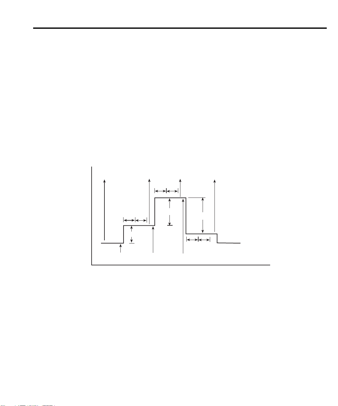
The pulse measurement period T can be selected manually or be automatically set by the
Model 2306. First, the user must specify a trigger level that serves as a threshold to initiate
integration process, i.e., at t = 0. Once the trigger level is selected, the output is turned on and
the pulsed load is operational, the 2306 can be prompted to automatically determine the high
time, low time, and average time in pulsed current mode according to Figure 6. These parameters
may also be set manually from the front panel or over the GPIB bus.
Figure 6
Pulsed waveform
High current level
Trigger
level
Low current level
High
time
Average time
Low
time
Average current
level
NOTE
The pulsed waveform in Figure 6 shows trigger level and the high, low, and average
times set by the Model 2306 using the auto-time feature.

12 Front panel operation
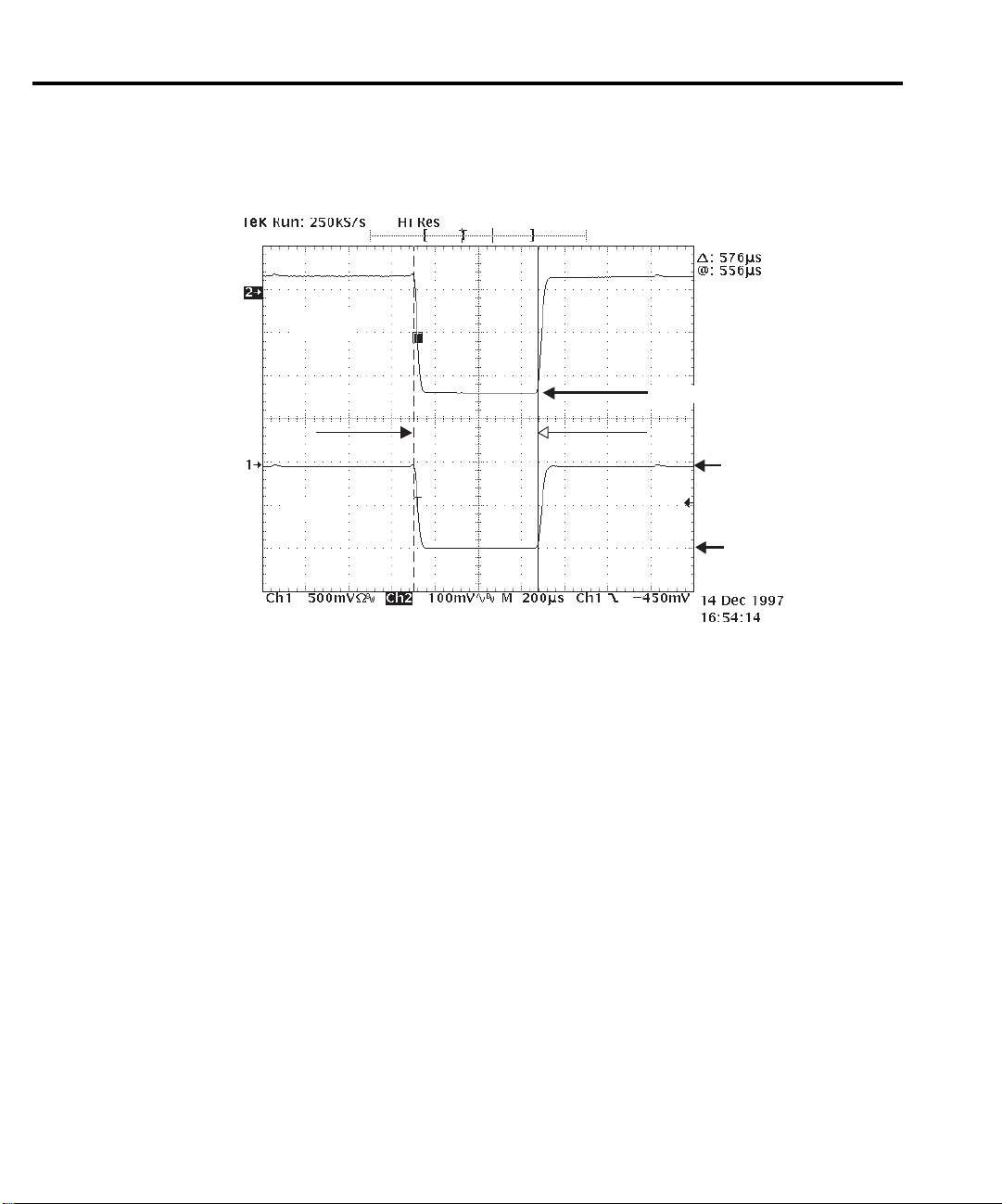
The pulsed response of a device is rarely a perfect square wave. Figure 7 shows the current
response of a typical GSM handset during the transmit portion of the data frame. Using the
built in auto-time feature with a trigger threshold of 0.2 amp and no trigger delay, the
Model 2306 will automatically set the HIGH integration time, denoted by TH1, to 533µs.
For this value of HIGH integration time, the effect of the current transient at the beginning
of the pulse is included in the measurement. Although in this example the effect of the
current transient on the measurement is small, the user can eliminate the effect of the
transient by adding a suitable amount of trigger delay. In this case, a delay of 100µs is
sufficient to eliminate the effect of transient, approximately 70µs, from the measurement.
Accordingly, the HIGH integration time, TH2, must be reduced, in this case 300µs was
chosen, so the integration time does not extend into a section of the pulse the user does not
want to measure.
Figure 7
Eliminating the effect of a current transient on a pulse current measurement
Trigger Threshold 0.2 A
Trigger delay 100 µsec
NOTE
In Figure 7, a trigger delay of 100µs is used to eliminate the effect of a current
transient on the pulse current measurement.
~ 1500mA
TH1 = 533µsec
TH2 = 300µsec

Front panel operation 13
Front panel operation for performing pulse current measurements
All of the following settings are available in sub-menus of PULSE CURRENT #1/#2 main
menu item. Scroll through the main menu and when PULSE CURRENT #1/#2 is displayed,
press “ENTER” to access the sub-menus.
Turn on the output
Press the OPERATE key after setting the appropriate voltage and current limits for the DUT.
Select CURRENT RANGE
For Models 2306-PJ and 2302-PJ, select 500mA or 5A. For Models 2306, 2306-VS, and
2302, the 5A range is automatically selected.
Set trigger level and range
“TRIG LEVEL RANGE” and “TRIGGER LEVEL” sub-menus
Battery Channel (#1) — On the 5A current range, the trigger level can be set for either the
5A, 1A, or 100mA range.
Trigger level ranges: 5A range: 0–5A in 5mA steps
1A range: 0–1A in 1mA steps
100mA range: 0–100mA in 0.1mA steps
“TRG LEV mA RANGE” and “TRIG LEVEL mA” sub-menus
Battery Channel (#1) (Models 2306-PJ and 2302-PJ) — On the 500mA current range, the
trigger level can be set for either the 500mA, 100mA, or the 10mA range.
Trigger level ranges: 500mA range: 0–500mA in 0.5mA steps
100mA range: 0–100mA in 0.1mA steps
10mA range: 0–10mA in 0.1mA steps
To change the range for the trigger level setting, place the blinking cursor on the “A” at the
far right end of line two of the display, and press the UP or DOWN key. After keying in the
trigger level (in amps), press ENTER to update the displayed range for that
only.
Charger Channel (#2) — Set the trigger level from 0 to 5A in 5mA steps.
Same as battery channel but settings for one range only 5A range: 0–5A in 5mA steps.
If the trigger level is incorrect or the DUT is not functioning properly, the “PULSE CURR
TRIG NOT DETECTED” message will be displayed. (See note No Pulses Detected message on
page 15.)
trigger level setting
Integration time (manual setting) “AVERAGE TIME”, “LOW TIME”, and “HIGH TIME”
sub-menus
The values for HIGH, LOW, and AVERAGE time may be changed in
with the UP and DOWN keys. Range of values is 33.3333
µ
sec to 833.33msec.
33.3333 µsec
intervals

14 Front panel operation
Integration time (auto time setting) “AUTO TIME” sub-menu
Press ENTER when “ACQUIRE TIMES” appears on the display. If the correct trigger level
is selected in the previous step and the DUT is operating, the Model 2306 will automatically
determine the HIGH, LOW, and AVERAGE times. If the trigger level is incorrect or the DUT is
not functioning properly, the message “PULSE CURR TRIG NOT DETECTED” will be
displayed. (See note No Pulses Detected message on page 15.)
Trigger delay (if necessary) channel #1 and channel #2:
The trigger level is changed in the TRIGGER LEVEL sub-menu by pressing the
key.
UP or DOWN
Range is 0 – 0.100sec in 10
NOTE
The high, low, or average integration times can be set either manually or
automatically. When a pulse is detected, there is a 15µsec trigger latency before the
integration time begins. An additional user trigger delay can be set to allow the
leading edge pulse overshoot to settle. Regardless of the user trigger delay setting,
the internal trigger delay is always present.
µ
sec increments.
Average readings count (if necessary) Channel #1 and Channel #2:
The AVERAGE READINGS sub-menu of the PULSE CURRENT #1/#2 menu item is used
to set the
measurements (integrations) to average for each reading. Range is
average readings count for pulse current measurements. This count specifies the number of
1–100.
Pulse current display mode
Pulse current measurements are displayed with the pulse current display mode selected. This
display mode is selected as follows:
NOTE
1. Press the DISPLAY key to access the display menu.
2. If the desired active display is not selected, use the LEFT and RIGHT keys to toggle the
3. Press the UP or DOWN key until “PULSE CURRENT” is displayed, and press ENTER.
4. Use the UP or DOWN key to display the desired pulse measurement; high, low, or
To display measured readings if the instrument is in the settings mode, press the SET
key until the blinking stops (the measured readings can then be displayed). To
determine if the instrument is in the settings mode, check for a blinking cursor in a
digit of the voltage or current field (if present, the instrument is in the settings mode).
active display. The top line of the display will show which output channel is active.
average.
NOTE No Pulses Detected message
If no pulses are detected, current will not be measured (i.e., -----A), and the “NO
PULSE” message will be displayed. The “NO PULSE” message is displayed with
dashes or the last valid pulse reading. Dashes are shown if the pulse-current
measurement settings are not appropriate for detecting pulses. The last valid pulse
is shown if the pulse disappears while taking readings and no change in pulse
settings was made.
Pulses are not detected with the output OFF. With the output ON, pulses will not be
detected if the trigger level is too low or too high. Adjust the trigger level as necessary and toggle back to the display mode until pulse measurements are displayed.
Front panel operation 15
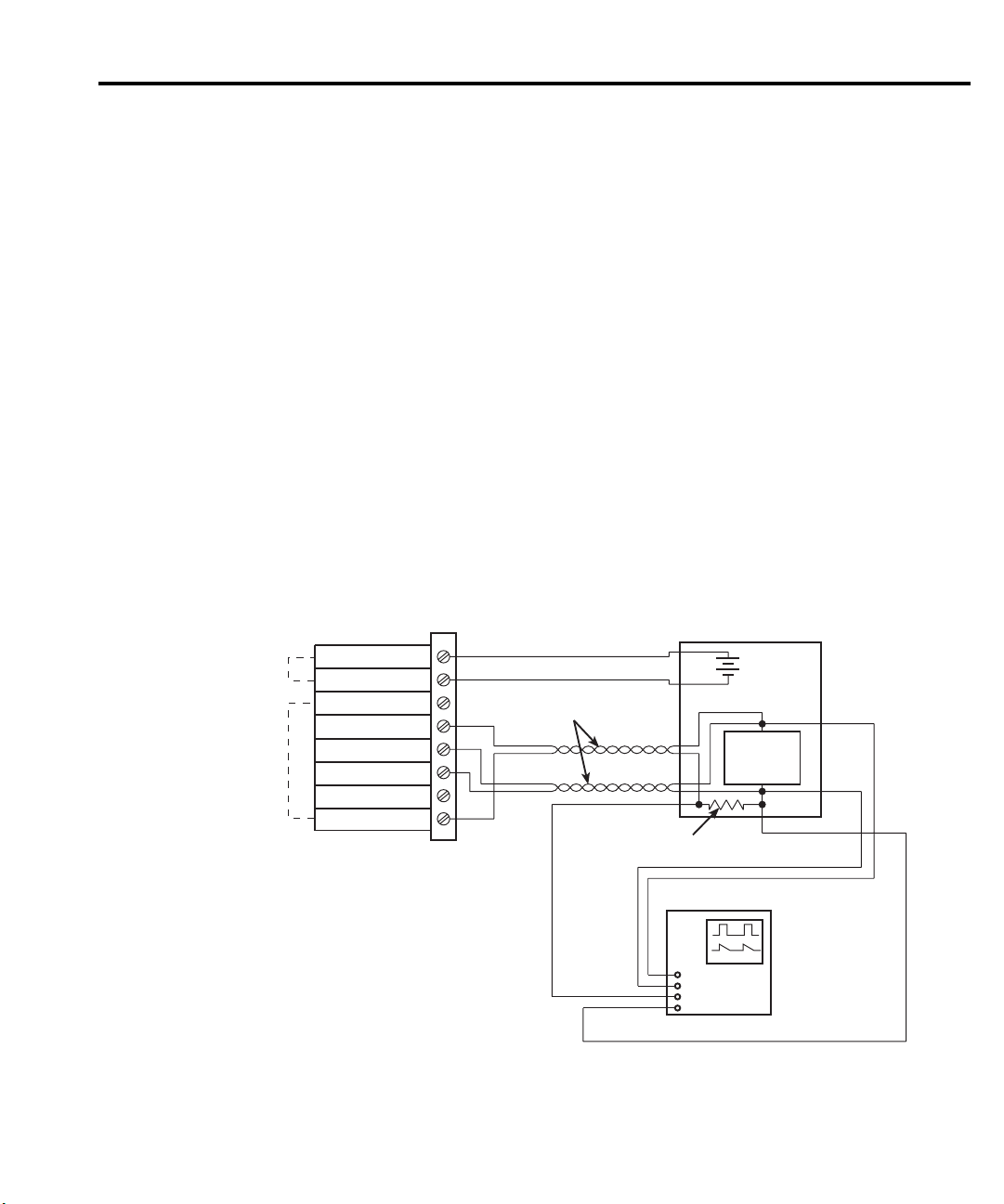
NOTE
If possible, the user should always use an oscilloscope to determine the timing and
transient characteristics of a DUT. The waveform information is very useful in
setting up the Model 2306, reducing setup time, and achieving maximum
performance and productivity. The voltage and current characteristics of the DUT
can be determined with a two-channel oscilloscope, a 0.1 ohm resistor used as a
current sense resistor, and a voltage probe at the DUT as shown in Figure 8.
Figure 8
Circuit — determining the dynamic voltage and current characteristics of a DUT
Quick Disconnect
DVM input
Model 2306
source input/output
DVM +
DVM -
Source +
Source -
Sense +
Sense -
Source +
Source -
Connector
Twisted pair
0.1W Current
sense resistor
External Test Circuit
DUT
NOTE
Channel 1
Channel 2
Oscilloscope
Figure 8 contains a simple circuit for determining the dynamic voltage and current
characteristics of the DUT using a 2-channel oscilloscope, a 0.1 ohm resistor used
as a current sense resistor, and a voltage probe at the DUT.

16 Front panel operation
Programming examples: pulse current measurements
The following command sequence will return the average of 10 peak pulse current
measurements:
Battery channel (#1)
Command Description
SENS:RANG 5 ‘ Select 5A range.
VOLT 15 ‘ Set output voltage to 15V.
CURR 0.75 ‘ Set current limit to 750mA.
OUTP ON ‘ Turn output on.
SENS:PCUR:SYNC ON ‘ Enable trigger synchronization.
SENS:PCUR:AVER 10 ‘ Set average count to 10.
SENS:PCUR:SYNC:TLEV:RANG 0.5 ‘ Select the 1A trigger level range.
SENS:PCUR:SYNC:TLEV:ONE 0.1 ‘ Set trigger level to 100mA for 1A trigger level
SENS:PCUR:TIME:AUTO ‘ Set integration times automatically.
SENS:PCUR:SYNC:DEL 50e-3 ‘ Set trigger delay to 50msec.
SENS:FUNC “PCUR” ‘ Select pulse current function.
SENS:PCUR:MODE HIGH ‘ Configure to measure peak pulse.
READ? ‘ Trigger 10 measurement conversions and return
range.
the average of those 10 conversions. The average
of the 10 conversions is displayed on the front
panel. Each of the 10 conversions syncs to the
rising edge.

Front panel operation 17
Charger channel (#2)
Command Description
SENS2:RANG 5 ‘ Select 5A range.
SOUR2:VOLT 15 ‘ Set output voltage to 15V.
SOUR2:CURR 0.75 ‘ Set current limit to 750mA.
OUTP2 ON ‘ Turn output on.
SENS2:PCUR:SYNC ON ‘ Enable trigger synchronization.
SENS2:PCUR:AVER 10 ‘ Set average count to 10.
SENS2:PCUR:SYNC:TLEV 0.1 ‘ Set trigger level to 100mA.
SENS2:PCUR:TIME:AUTO ‘ Set integration times automatically.
SENS2:PCUR:SYNC:DEL 50e-3 ‘ Set trigger delay to 50msec.
SENS2:FUNC “PCUR” ‘ Select pulse current function.
SENS2:PCUR:MODE HIGH ‘ Configure to measure peak pulse (trigger on).
READ2 ‘ Trigger 10 measurement conversions and return the
average of those 10 conversions. The average of the
10 conversions is displayed on the front panel. Each
of the ten conversions syncs to the rising edge.

18 Front panel operation
Long integration mode
In the long integration mode, a current measurement results from a continuous integration of
the dynamic current for a period ranging from approximately 850ms to 60sec set in 1msec
increments. The Model 2306 can determine the integration time automatically or the user can
set the integration time manually from the front panel. A pulse edge can be used to trigger the
start of the measurement as shown in Figure 9. Select RISING to use a rising pulse edge to start
the measurement. Select FALLING to use a falling pulse edge to start the measurement. A third
option is available if you do not want measurements controlled by pulse edges. With NEITHER
selected, measurements will start as soon as the long integration function is selected. Note that
a pulse has to be detected before a RISING or FALLING pulse edge can trigger a long
integration measurement (see "Set trigger level and range" on page 19). To average over several
pulse periods, the user must enter the sum of the pulse periods as the integration time.
The GPIB commands TIMEOUT, SEARCH, DETECT, and FAST are available exclusively
in the long integration mode to optimize measurement speed. For the relevance and use of these
commands regarding a particular measurement application, refer to the Model 2306 Instruction
Manual, Section 4, Long Integration Measurements.
Figure 9
Pulsed waveform
Trigger
level
Average current
Integration time
(trigger set to rising)
Integration time
(trigger set to falling)
NOTE
The pulse waveform contained in Figure 9 shows trigger level and the integration
time used by the Model 2306 for pulse current measurements.
Front panel operation for performing long integration measurements
All of the following settings are available in sub-menus of the LONG INTEGRAT #1/#2 main
menu item. Scroll through the main menu and when LONG INTEGRAT #1/#2 is displayed
press “ENTER” to access the sub-menus.
Turn on the output
Press the OPERATE key after setting the appropriate voltage and current limits for the DUT.
Select CURRENT RANGE
For Models 2306-PJ and 2302-PJ, select 500mA or 5A. For Models 2306, 2306-VS, and
2302, the 5A range is automatically selected.

Front panel operation 19
Set trigger level and range
“TRIG LEVEL RANGE” and “TRIGGER LEVEL” sub-menus
Battery Channel (#1) — On the 5A current range, the trigger level can be set for either the
5A, 1A, or 100mA range.
Trigger level ranges: 5A range: 0–5A in 5mA steps
1A range: 0–1A in 1mA steps
100mA range: 0–100mA in 0.1 mA steps
“TRG LEV mA RANGE” and “TRIG LEVEL mA” sub-menus
Battery Channel (#1) (Models 2306-PJ and 2302-PJ) — On the 500mA current range, the
trigger level can be set for either the 500mA, 100mA, or the 10mA range.
Trigger level ranges: 500mA range: 0–500mA in 0.5mA steps
100mA range: 0–100mA in 0.1mA steps
10mA range: 0–10mA in 0.1mA steps
To change the range for the trigger level setting, place the blinking cursor on the “A” at the
far right end of line two of the display, and press the UP or DOWN key. After keying in the
trigger level (in amps), press ENTER to update the displayed range for that trigger level setting
only.
Charger Channel (#2) — Set the trigger level from 0 to 5A in 5mA steps.
NOTE This is the same as battery channel but settings are for only one range, the 5A range:
0–5A in 5mA steps.
If the trigger level is incorrect or the DUT is not functioning properly, the message
“LONG INT TRIG NOT DETECTED” will be displayed. (See the LONG INT TRIG NOT
DETECTED
note on page 20.)
Trigger edge – “TRIGGER EDGE” sub-menus
Toggle between the RISING, FALLING, and NEITHER settings with the UP and DOWN
keys.
With NEITHER selected, measurements will start as soon as the long integration function is
selected.
Timeout – “TIMEOUT” sub-menu
When the TIMEOUT value is reached, NO PULSE is displayed (top line of the front panel
display). The value for TIMEOUT should be set to a value greater than the long integration time
for a long integration reading.
Manually setting long integration time (“INTEGRATION TIME” sub-menu)
The value for LINT INT TIME for channel #1 or channel #2 can be specified in 0.850 sec to
60 sec (i.e. @ 60Hz) with the UP and DOWN keys.

20 Front panel operation
Automatically setting long integration time (“AUTO TIME” sub-menu)
Press ENTER when “LINT AUTOTIME #1, #2”, “ACQUIRE TIMES” appears on the
display. If the correct trigger level is selected in the previous step and the DUT is operating, the
Model 2306 will automatically determine the INTEGRATION times. If the trigger level is
incorrect or the DUT is not functioning properly, the message “LONG INT TRIG NOT
DETECTED” will be displayed.
page 20.)
Long integration display mode
Long integration measurements are displayed with the long integration display mode
selected. This display mode is selected as follows:
NOTE To display measured readings if the instrument is in the settings mode, press the SET
1. Press the DISPLAY key to access the display menu.
2. If the desired active display is not selected, use the LEFT and RIGHT keys to toggle the
active display. The top line of the display will show which output channel is active.
3. Press the UP or DOWN key until “LONG INTEGRATION” is displayed and press
ENTER.
4. To stop taking long integration readings, press any front panel key. As long as the
instrument remains in the long integration display state, the measurement process can be
resumed by pressing the UP or DOWN key.
(See the LONG INT TRIG NOT DETECTED note on
key until the blinking stops (the measured readings can then be displayed). To
determine if the instrument is in the settings mode, check for a blinking cursor in a
digit of the voltage or current field (if present, the instrument is in the setting mode).
NOTE LONG INT TRIG NOT DETECTED message
This message may take a few seconds to appear. With the trigger edge set to
NEITHER, this message may appear if level setting causes no rising edge detection.
A valid trigger level is not required if the trigger edge is set to NEITHER. For the
battery channel (#1), this message will only appear if the range of the trigger level
setting matches the selected trigger level range. For the charger channel #2, the
trigger level range setting is not user selectable.
NOTE If you select AUTO TIME to set the integration time, the pulse timeout message
“LONG INT TRIG NOT DETECTED” will display if the output is OFF. This
message indicates that the integration time has not been updated. To update the
integration time, select AUTO TIME after the output is turned ON.

Front panel operation 21
Programming examples: long integration measurements
The following command sequence will trigger and return one long integration measurement:
Battery channel (#1)
Command Description
SENS:RANG 5 ‘ Select 5A range.
VOLT 15 ‘ Set output voltage to 15V.
CURR 0.75 ‘ Set current limit to 750mA.
OUTP ON ‘ Turn output on.
SENS:LINT:TLEV:RANG 0.5 ‘ Select 1A trigger level range.
SENS:LINT:TEDG RISING ‘ Select rising trigger edge to initiate measurement.
SENS:LINT:TLEV:ONE 0.1 ‘ Set trigger level to 100mA for 1A trigger level range.
SENS:LINT:TIME:AUTO ‘ Set integration time automatically for single pulse.
SENS:FUNC “LINT” ‘ Select long integration function.
READ? ‘ Trigger and return one reading and reading shown on
display.
Charger channel (#2)
Command Description
SENS2:RANG 5 ‘ Select 5A range.
SOUR2:VOLT 15 ‘ Set output voltage to 15V.
SOUR2:CURR 0.75 ‘ Set current limit to 750mA.
OUTP2 ON ‘ Turn output on.
SENS2:LINT:TEDG RISING ‘ Select rising trigger edge to initiate measurement.
SENS2:LINT:TLEV 0.1 ‘ Set trigger level to 100mA.
SENS2:LINT:TIME:AUTO ‘ Set integration time automatically for single pulse.
SENS2:FUNC “LINT” ‘ Select long integration function.
READ2? ‘ Trigger and return one reading and reading shown on
display.

22 Advanced features
Advanced features
Simulating battery impedance
The electronic resistance of batteries varies according to a variety of factors such as
chemistry, cell construction, number of charge/discharge cycles, temperature, and depth of
discharge. If a battery is used as a source in a circuit with a dynamic load, changes in the voltage
across the load will be produced proportional to the electronic resistance of the battery and other
sources of resistance in the circuit. If the peak load current is high enough or the electronic
resistance of the battery and the resistance between the source and the DUT is large, the voltage
drop compromises the performance of the device.
This phenomenon occurs in TDMA and GSM cellular handsets where the magnitude of the
“ON/OFF” current during transmission varies by as much as a factor of 20. In the absence of
any filtering capacitance between the battery and the RF power amplifier, the handset will shut
off if the supply voltage is below the operating threshold for periods as short as several
microseconds.
Figure 10 shows a simple schematic of a battery. This battery is represented by an ideal
voltage source, V
interconnects having resistance R
cell
, with internal impedance, Ri(t), and is connected to a DUT with
interconnect
.
Figure 10
Battery schematic
R
If R
interconnect
of the pulse, R
Vt() ViIt()R
interconnect
Ri(t)
Cell or Battery Pack
V
cell
R
interconnect
DUT
is small compared to Ri(t) and if Ri(t) is relatively constant during the length
(t) ~ Ri, then the voltage across the DUT may be expressed as:
i
–=
i
I(t)
where I(t) is the time varying current through the battery.
V(t)

Advanced features 23
Figure 11 shows the actual performance of typical Li ion, NiMH, and NiCd handset battery
packs with a dynamic load, shown in Figure 12, simulating a GSM handset during transmission.
The pulse minimum voltage is the voltage at the battery terminals during the transmit, or high
current portion, of the data frame. The average battery voltage is the voltage across the terminals
measured with a 6∫ digit DMM at approximately 50 readings per second. The figure shows the
pulse minimum voltage reaches the shutdown threshold of 5.7V before the average battery
voltage. The difference between the pulse minimum and average battery voltage also varies as a
function of the electronic resistance with time. Figure 13 shows the variations for specific
battery packs and ranges between 200 and 500mV. The results of these measurements prove that
the impedance of the battery must be considered when evaluating handset performance,
especially near the end of life for the battery pack.
Figure 11
Actual battery pack terminal voltage during GSM phone simulation
Li ion Average Battery Voltage
1
2
NiMH Average Battery Voltage
NiCd Average Battery Voltage
3
Li ion Battery Pulse Minimum Voltage
4
NiMH Battery Pulse Minimum Voltage
5
NiCd Battery Pulse Minimum Voltage
9.00
6
8.50
8.00
7.50
7.00
6.50
Battery Voltage, V
6.00
5.50
5.00
0.0 2.0 4.0 6.0 8.0 10.0
1
4
2
3
6.59
6
5
8.15
7.18
5.7V
Time, hrs
NOTE Figure 11 shows the average and minimum battery pack terminal voltage during a
load pulse from a dynamic load simulating a GSM phone.
24 Advanced features
Figure 12
Simulated GSM phone current profile
Voltage
Pulse Minimum Voltage
-0.030 amps
Current
-1.200 amps
NOTE The simulated GSM phone current profile contained in Figure 12 shows a standby
current of 0.030A, a transmit current of 1.2A, and the pulse minimum voltage during
the transmit frame.

Figure 13
Electronic resistance of NiCd, NiMH, and Li ion battery packs
0.40
Li ion
0.35
0.30
NiMH
0.25
Advanced features 25
0.20
NiCd
0.15
Output Impedance, ohms
0.10
0.0
2.0 4.0 6.0 8.0 10.0
Time, hrs
NOTE Figure 13 shows electronic resistance for battery packs during a simulated GSM
phone pulsed discharge from full charge to 5.5 volts.
Variable output impedance control on channel #1
Channel #1 of the Model 2306 has a variable output impedance control that can be used to
simulate the impedance of a battery pack. The output impedance may be set from 0.00 ohms
(default condition) to 1.00 ohms in 0.01 ohm increments from the front panel or over the GPIB
bus.
Figure 14 shows the output voltage and current response of channel #1 with a GSM phone
for output impedance values of 0.00, 0.05, and 0.10 ohms. The voltage drop, 70mV in c and
140mV in e, is approximately equal to the dynamic load current, 1.4A, multiplied by the output
impedance, c (0.05 ohms) and e (0.10 ohms).

26 Advanced features
Figure 14
Effect of variable output impedance control
~1.4 amps
a
70mV
c
140mV
b
d
e
NOTE Figure 14 contains the effect of the variable output impedance control of the
Model 2306 on the current and voltage performance of a GSM handset.
f

Advanced features 27
Two methods are used to determine the impedance value of the cell or battery pack. The first
method uses data from the battery manufacturer or another source and is simply entered into the
Model 2306 from the front panel or over the GPIB bus. The second method involves a simple
series of measurements as follows.
Figure 15
Voltage drop sample (with supplied Li ion battery pack)
VH – VL = 0.348 V
NOTE Figure 15 shows the voltage drop during the transmit portion of the pulse with the
supplied Li ion battery pack. See Figure 16 for the comparative illustration using the
Model 2306.
Figure 15 shows the transient voltage response at the battery terminals with the handset
battery. Using Figure 15, the voltage drop during the transmit portion of the pulse of a GSM
phone with the supplied Li ion battery is 0.348V. Using the pulse current mode of the battery
channel the measured current during the transmit portion of the data frame is I
the idle portion of the data frame is I
= 0.082A. To estimate Ri from the measured voltage, we
L
= 1.536A and
H
use
R
i
VHV
--------------------
I
HIL
0.348V
L–
-----------------
–
1.454A
==≅
0.239
Ω
:
Using this value for the output impedance setting in the battery channel, the voltage drop
across the output terminals, as shown in Figure 16, is 0.360V. This value is in agreement, to
within 3%, with the results obtained with the battery included with the handset.
NOTE Figure 16 shows the voltage drop during the transmit portion of the pulse of a GSM
phone using the Model 2306 battery channel with output impedance set to 0.24Ω.
See Figure 15 for actual Li ion battery results.

28 Advanced features
Figure 16
Voltage drop sample (with Model 2306 and output impedance set at 0.24Ω)
VH – VL = 0.360V
Variable output bandwidth
Testing the performance of the battery charger circuitry in a handset does not require the high
bandwidth performance in channel #1 or channel #2 of the Model 2306. Since a charger circuit
is a voltage regulated circuit, it resembles a high capacitance load to the output of the
Model 2306. For this type of application, the LOW bandwidth output mode provides increased
stability and eliminates oscillations that may occur. The LOW bandwidth output mode is
selectable from the front panel or over the GPIB bus of the Model 2306.
Front panel operation for output bandwidth
The following settings are available in main menu under OUT BANDWIDTH #1,#2. Use the
UP or DOWN keys to set the desired output bandwidth, either HIGH or LOW.
GPIB commands
Command Description
:OUTPut:BANDwidth HIGH or LOW ‘ Bandwidth when the output state is ON and
:OUTPut2:BANDwidth HIGH or LOW ‘ Same as above, but for output channel #2.
current range is set to 5A. When output is
OFF, the bandwidth is LOW. When current
range is 5mA, bandwidth is LOW.
External triggering
NOTE External triggering and associated voltage stepping discussed below is available
only via remote with the Model 2306-VS. See Section 6 of the Model 2306
Instruction Manual for more detailed information on these features.
Description
The Model 2306-VS has four rear panel mounted BNC connectors (two inputs and two outputs) allowing external triggering and handshaking for both channels. The triggering capability
adds the ability to automatically step through different voltages and take measurements at each
step under the control of external triggering. A typical trigger sequence is shown in Figure 17.
(The exact sequence will depend on how the instrument is programmed.)
Figure 17
Typical trigger sequence
Advanced features 29
Output
Voltage
Trigger
Out (1)
Trigger In (2)
Trigger
Out (6)
Delay
Meas.
Delay
(5)
(4)
Step (3)
Trigger In (7) Trigger In
Meas.
Step
Time
Trigger
Out
Delay
Trigger
Out
Numbered sequence shown
Step
Meas.
on first step correspond to
steps in text.
Delay = Programmed Delay
Meas. = Measurement Period
The sequence is as follows:
1. Sending TRIG:EXT:ENAB or TRIG:EXT:ENAB:INIT will generate a trigger output
pulse when the instrument is ready for trigger in pulses
2. The trigger input pulse applied to the TRIGGER IN jack is detected.
3. The voltage steps to the next value (if voltage stepping is enabled).
4. The unit waits for the programmed delay period.
5. Measurements are taken (if enabled).
6. The unit outputs the trigger output pulse on the TRIGGER OUT jack to indicate that the
step has been completed.
7. The complete sequence in steps 2-6 repeats for the programmed number of steps
(20 maximum).

30 Advanced features
External trigger commands
There are a number of commands that support Model 2306-VS external triggering and
associated voltage stepping. See Table 6-1 in Section 6 of the Model 2306 Instruction Manual
for details.
Programming example: external triggering with voltage stepping
The command sequence below will step through six voltages from 1V to 6V without taking
readings. Note that six external trigger-in, trigger-out pulse sequences are required, one per step.
Battery channel (#1) voltage step
Command Description
*RST ‘ Reset the 2306-VS
:VOLT 0 ‘ Set the voltage
:CURR 1.75 ‘ Set the current limit
:OUTP ON ‘ Turn on the output.
:SENS:FUNC 'VOLT' ‘ Select the voltage functionality
:TRIG:EXT:BOTH NONE ‘ Select channel 1 to only affect channel 1
:TRIG:EXT:STEP 1,1,1 ‘ Step 1 voltage is 1 with 1 second delay
:TRIG:EXT:STEP 2,2,2 ‘ Step 2 voltage is 2 with 2 second delay
:TRIG:EXT:STEP 3,3,1 ‘ Step 3 voltage is 3 with 1 second delay
:TRIG:EXT:STEP 4,4,2 ‘ Step 4 voltage is 4 with 2 second delay
:TRIG:EXT:STEP 5,5,1 ‘ Step 5 voltage is 5 with 1 second delay
:TRIG:EXT:STEP 6,6,2 ‘ Step 6 voltage is 6 with 2 second delay
:TRIG:EXT:STEP:READ NONE ‘ No measurements while stepping voltage
:TRIG:EXT:STEP:VOLT ON ‘ Enable voltage stepping
:TRIG:EXT:STEP:POIN 6 ‘ Set for six step voltages.
:TRIG:EXT:ENAB ON ‘ Enable voltage stepping on channel 1
:TRIG:EXT:ENAB OFF ‘ Disable voltage stepping.
‘ Apply trigger pulse to 2306-VS trig. input.
‘ Wait for pulse on 2306-VS trig. output.
‘ Repeat trigger pulses for all six steps.

Index
N
NPLC rate 8
A
Actual V and I mode 7
Advanced features 22
Average readings 8
D
DVM input mode 10
E
External trigger commands 30
External triggering 29
F
Front panel operation 6
Front panel operation for output bandwidth 28
Front panel operation for performing long
integration measurements 18
Front panel operation for performing pulse
current measurements 13
I
Introduction 2
L
Long integration mode 18
P
Performance features 3
Programming example
external triggering with voltage
stepping 30
Programming examples
long integration measurements 21
making voltage measurements with the
DVM 10
outputting and reading back V and I 9
pulse current measurements 16
Proper connection of the supply to the DUT 4
Pulse current mode 10
S
Setting the output voltage, current range, and
current limit 7
Simulating battery impedance 22
T
Turning supply output ON/OFF 7
V
Variable output bandwidth 28
Variable output impedance control on
channel #1 25
M
Menu controls 6


Specifications are subject to change without notice.
All Keithley trademarks and trade names are the property of Keithley Instruments, Inc.
All other trademarks and trade names are the property of their respective companies.
Keithley Instruments, Inc. 28775 Aurora Road • Cleveland, Ohio 44139 • 440-248-0400 • Fax: 440-248-6168
1-888-KEITHLEY (534-8453) • www.keithley.com
Sales Offices: BELGIUM: Bergensesteenweg 709 • B-1600 Sint-Pieters-Leeuw • 02-363 00 40 • Fax: 02-363 00 64
CHINA: Yuan Chen Xin Building, Room 705 • 12 Yumin Road, Dewai, Madian • Beijing 100029 • 8610-82251886 • Fax: 8610-82251892
FINLAND: Halsuantie 2 • 00420 Helsinki, Finland • 09-53 06 65 60 • Fax: 09-53 06 65 65
FRANCE: 3, allée des Garays • 91127 Palaiseau Cédex • 01-64 53 20 20 • Fax: 01-60 11 77 26
GERMANY: Landsberger Strasse 65 • 82110 Germering • 089-84 93 07-40 • Fax: 089-84 93 07-34
GREAT BRITAIN: Unit 2 Commerce Park, Brunel Road • Theale, Berkshire RG7 4AB • 0118 -929 75 00 • Fax: 0118- 929 75 19
INDIA: 1/5, Eagles Street • Langford Town • Bangalore 560 025 • 080 212 80-27 • Fax: 080 212 80 05
ITALY: Viale San Gimignano, 38 • 20146 Milano • 02-48 39 16 01 • Fax: 02-48 30 22 74
JAPAN: New Pier Takeshiba North Tower 13F • 11-1, Kaigan 1-chome • Minato-ku, Tokyo 105-0022 • 81-3-5733-7555 • Fax: 81-3-5733-7556
KOREA: 2FL., URI Building • 2-14 Yangjae-Dong • Seocho-Gu, Seoul 137-888 • 82-2-574-7778 • Fax: 82-2-574-7838
NETHERLANDS: Postbus 559 • 4200 AN Gorinchem • 0183-63 53 33 • Fax: 0183-63 08 21
SWEDEN: c/o Regus Business Centre • Frosundaviks Allé 15, 4tr • 16970 Solna • 08-50 90 46 00 • Fax: 08-655 26 10
TAIWAN: 13F-3, NO. 6, Lane 99, Pu-Ding Road, Hsinchu, Taiwan, ROC. • 886-3-572-9077 • Fax: 886-3-572-9031
© Copyright 2003 Keithley Instruments, Inc.
Printed in the U.S.A.
5/03
 Loading...