

Page 1

Model 2001 Multimeter
Calibration Manual
A GREATER MEASURE OF CONFIDENCE
Page 2

Model 2001 Multimeter
Calibration Manual
©1992, Keithley Instruments, Inc.
All rights reserved.
Cleveland, Ohio, U.S.A.
Seventh Printing May 2004
Document Number: 2001-905-01 Rev. G
Page 3

WARRANTY
Keithley Instruments, Inc. warrants this product to be free from defects in material and workmanship for a period of 3 years from
date of shipment.
Keithley Instruments, Inc. warrants the following items for 90 days from the date of shipment: probes, cables, rechargeable batteries,
diskettes, and documentation.
During the warranty period, we will, at our option, either repair or replace any product that proves to be defective.
To exercise this warranty, write or call your local Keithley representative, or contact Keithley headquarters in Cleveland, Ohio. You
will be given prompt assistance and return instructions. Send the product, transportation prepaid, to the indicated service facility.
Repairs will be made and the product returned, transportation prepaid. Repaired or replaced products are warranted for the balance
of the original warranty period, or at least 90 days.
LIMITATION OF WARRANTY
This warranty does not apply to defects resulting from product modification without Keithley’s express written consent, or misuse
of any product or part. This warranty also does not apply to fuses, software, non-rechargeable batteries, damage from battery leakage, or problems arising from normal wear or failure to follow instructions.
THIS WARRANTY IS IN LIEU OF ALL OTHER WARRANTIES, EXPRESSED OR IMPLIED, INCLUDING ANY IMPLIED
WARRANTY OF MERCHANTABILITY OR FITNESS FOR A PARTICULAR USE. THE REMEDIES PROVIDED HEREIN
ARE BUYER’S SOLE AND EXCLUSIVE REMEDIES.
NEITHER KEITHLEY INSTRUMENTS, INC. NOR ANY OF ITS EMPLOYEES SHALL BE LIABLE FOR ANY DIRECT,
INDIRECT, SPECIAL, INCIDENTAL OR CONSEQUENTIAL DAMAGES ARISING OUT OF THE USE OF ITS INSTRUMENTS AND SOFTWARE EVEN IF KEITHLEY INSTRUMENTS, INC., HAS BEEN ADVISED IN ADVANCE OF THE
POSSIBILITY OF SUCH DAMAGES. SUCH EXCLUDED DAMAGES SHALL INCLUDE, BUT ARE NOT LIMITED TO:
COSTS OF REMOVAL AND INSTALLATION, LOSSES SUSTAINED AS THE RESULT OF INJURY TO ANY PERSON, OR
DAMAGE TO PROPERTY.
A G R E A T E R M E A S U R E O F C O N F I D E N C E
Keithley Instruments, Inc.
Corporate Headquarters • 28775 Aurora Road • Cleveland, Ohio 44139 • 440-248-0400 • Fax: 440-248-6168 • 1-888-KEITHLEY (534-8453) • www.keithley.com
Belgium: Sint-Pieters-Leeuw • 02-363 00 40 • Fax: 02-363 00 64 • www.keithley.nl Italy: Milano • 02-48 39 16 01 • Fax: 02- 48 39 16 28 • www.keithley.it
China: Beijing • 8610-82251886 • Fax: 8610-82251892 • www.keithley.com.cn Japan: Tokyo • 81-3-5733-7555 • Fax: 81-3-5733-7556 • www.keithley.jp
Finland: Helsinki • 09-5306-6560 • Fax: 09-5306-6565 • www.keithley.com Korea: Seoul • 82-2-574-7778 • Fax: 82-2-574-7838 • www.keithley.com
France: Saint-Aubin • 01-64 53 20 20 • Fax: 01-60 11 77 26 • www.keithley.fr Netherlands: Gorinchem • 0183-635333 • Fax: 0183-630821 • www.keithley.nl
Germany: Germering • 089/84 93 07-40 • Fax: 089/84 93 07-34 • www.keithley.de Singapore: Singapore • 65-6747-9077 • Fax: 65-6747-2991 • www.keithley.com
Great Britain: Theale • 0118 929 7500 • Fax: 0118 929 7519 • www.keithley.co.uk Sweden: Solna • 08-509 04 600 • Fax: 08-655 26 10 • www.keithley.com
India: Bangalore • 91-80 2212 8027 • Fax: 91-80 2212 8005 • www.keithley.com Tai wa n : Hsinchu • 886-3-572-9077 • Fax: 886-3-572-9031 • www.keithley.com.tw
3/04
Page 4

Manual Print History
The print history shown below lists the printing dates of all Revisions and Addenda created for this manual. The Revision
Level letter increases alphabetically as the manual undergoes subsequent updates. Addenda, which are released between Revisions, contain important change information that the user should incorporate immediately into the manual. Addenda are numbered sequentially. When a new Revision is created, all Addenda associated with the previous Revision of the manual are
incorporated into the new Revision of the manual. Each new Revision includes a revised copy of this print history page.
Revision A (Document Number 2001-905-01) ....................................................................................... April 1992
Revision B (Document Number 2001-905-01) ........................................................................................ June 1992
Revision C (Document Number 2001-905-01) ........................................................................................ May 1993
Addendum C (Document Number 2001-905-02)..................................................................................... June 1993
Addendum C (Document Number 2001-905-03)............................................................................November 1993
Addendum C (Document Number 2001-905-04)................................................................................ January 1995
Revision D (Document Number 2001-905-01) .................................................................................... August 1995
Revision E (Document Number 2001-905-01) ........................................................................................ April 1996
Revision F (Document Number 2001-905-01)................................................................................November 2003
Revision G (Document Number 2001-905-01) ........................................................................................ May 2004
All Keithley product names are trademarks or registered trademarks of Keithley Instruments, Inc.
Other brand and product names are trademarks or registered trademarks of their respective holders.
Page 5

Safety Precautions
The following safety precautions should be observed before using
this product and any associated instrumentation. Although some instruments and accessories would normally be used with non-hazardous voltages, there are situations where hazardous conditions
may be present.
This product is intended for use by qualified personnel who recognize shock hazards and are familiar with the safety precautions required to avoid possible injury. Read and follow all installation,
operation, and maintenance information carefully before using the
product. Refer to the manual for complete product specifications.
If the product is used in a manner not specified, the protection provided by the product may be impaired.
The types of product users are:
Responsible body is the individual or group responsible for the use
and maintenance of equipment, for ensuring that the equipment is
operated within its specifications and operating limits, and for ensuring that operators are adequately trained.
Operators use the product for its intended function. They must be
trained in electrical safety procedures and proper use of the instrument. They must be protected from electric shock and contact with
hazardous live circuits.
Maintenance personnel perform routine procedures on the product
to keep it operating properly, for example, setting the line voltage
or replacing consumable materials. Maintenance procedures are described in the manual. The procedures explicitly state if the operator
may perform them. Otherwise, they should be performed only by
service personnel.
Service personnel are trained to work on live circuits, and perform
safe installations and repairs of products. Only properly trained service personnel may perform installation and service procedures.
Keithley products are designed for use with electrical signals that
are rated Measurement Category I and Measurement Category II, as
described in the International Electrotechnical Commission (IEC)
Standard IEC 60664. Most measurement, control, and data I/O signals are Measurement Category I and must not be directly connected to mains voltage or to voltage sources with high transient overvoltages. Measurement Category II connections require protection
for high transient over-voltages often associated with local AC
mains connections. Assume all measurement, control, and data I/O
connections are for connection to Category I sources unless otherwise marked or described in the Manual.
Exercise extreme caution when a shock hazard is present. Lethal
voltage may be present on cable connector jacks or test fixtures.
The American National Standards Institute (ANSI) states that a
shock hazard exists when voltage levels greater than 30V RMS,
42.4V peak, or 60VDC are present. A good safety practice is to ex-
pect that hazardous voltage is present in any unknown circuit
before measuring.
Operators of this product must be protected from electric shock at
all times. The responsible body must ensure that operators are prevented access and/or insulated from every connection point. In
some cases, connections must be exposed to potential human contact. Product operators in these circumstances must be trained to
protect themselves from the risk of electric shock. If the circuit is
capable of operating at or above 1000 volts, no conductive part of
the circuit may be exposed.
Do not connect switching cards directly to unlimited power circuits.
They are intended to be used with impedance limited sources.
NEVER connect switching cards directly to AC mains. When connecting sources to switching cards, install protective devices to limit
fault current and voltage to the card.
Before operating an instrument, make sure the line cord is connected to a properly grounded power receptacle. Inspect the connecting
cables, test leads, and jumpers for possible wear, cracks, or breaks
before each use.
When installing equipment where access to the main power cord is
restricted, such as rack mounting, a separate main input power disconnect device must be provided, in close proximity to the equipment and within easy reach of the operator.
For maximum safety, do not touch the product, test cables, or any
other instruments while power is applied to the circuit under test.
ALWAYS remove power from the entire test system and discharge
any capacitors before: connecting or disconnecting cables or jumpers, installing or removing switching cards, or making internal
changes, such as installing or removing jumpers.
Do not touch any object that could provide a current path to the common side of the circuit under test or power line (earth) ground. Always
make measurements with dry hands while standing on a dry, insulated
surface capable of withstanding the voltage being measured.
The instrument and accessories must be used in accordance with its
specifications and operating instructions or the safety of the equipment may be impaired.
Do not exceed the maximum signal levels of the instruments and accessories, as defined in the specifications and operating information, and as shown on the instrument or test fixture panels, or
switching card.
When fuses are used in a product, replace with same type and rating
for continued protection against fire hazard.
Chassis connections must only be used as shield connections for
measuring circuits, NOT as safety earth ground connections.
If you are using a test fixture, keep the lid closed while power is applied to the device under test. Safe operation requires the use of a
lid interlock.
5/03
Page 6

If a screw is present, connect it to safety earth ground using the
wire recommended in the user documentation.
!
The symbol on an instrument indicates that the user should refer to the operating instructions located in the manual.
The symbol on an instrument shows that it can source or measure 1000 volts or more, including the combined effect of normal
and common mode voltages. Use standard safety precautions to
avoid personal contact with these voltages.
The symbol indicates a connection terminal to the equipment
frame.
The WA RN ING heading in a manual explains dangers that might
result in personal injury or death. Always read the associated information very carefully before performing the indicated procedure.
The CAUTION heading in a manual explains hazards that could
damage the instrument. Such damage may invalidate the warranty.
Instrumentation and accessories shall not be connected to humans.
Before performing any maintenance, disconnect the line cord and
all test cables.
To maintain protection from electric shock and fire, replacement
components in mains circuits, including the power transformer, test
leads, and input jacks, must be purchased from Keithley Instruments. Standard fuses, with applicable national safety approvals,
may be used if the rating and type are the same. Other components
that are not safety related may be purchased from other suppliers as
long as they are equivalent to the original component. (Note that selected parts should be purchased only through Keithley Instruments
to maintain accuracy and functionality of the product.) If you are
unsure about the applicability of a replacement component, call a
Keithley Instruments office for information.
To clean an instrument, use a damp cloth or mild, water based
cleaner. Clean the exterior of the instrument only. Do not apply
cleaner directly to the instrument or allow liquids to enter or spill on
the instrument. Products that consist of a circuit board with no case
or chassis (e.g., data acquisition board for installation into a computer) should never require cleaning if handled according to instructions. If the board becomes contaminated and operation is affected,
the board should be returned to the factory for proper cleaning/servicing.
Page 7

Table of Contents
1 Performance Verification
1.1 Introduction..........................................................................................................................................................1-1
1.2 Environmental conditions .................................................................................................................................... 1-1
1.3 Warm-up period ...................................................................................................................................................1-1
1.4 Line power ...........................................................................................................................................................1-1
1.5 Recommended test equipment .............................................................................................................................1-2
1.6 Verification limits ................................................................................................................................................1-2
1.7 Restoring default conditions ................................................................................................................................1-2
1.8 Verification procedures........................................................................................................................................1-4
1.8.1 DC volts verification.................................................................................................................................... 1-4
1.8.2 AC volts verification.................................................................................................................................... 1-5
1.8.3 DC current verification ..............................................................................................................................1-10
1.8.4 AC current verification ..............................................................................................................................1-11
1.8.5 Resistance verification ...............................................................................................................................1-13
1.8.6 Frequency accuracy verification................................................................................................................1-16
1.8.7 Temperature reading checks ...................................................................................................................... 1-17
2Calibration
2.1 Introduction..........................................................................................................................................................2-1
2.2 Environmental conditions .................................................................................................................................... 2-1
2.3 Warm-up period ...................................................................................................................................................2-2
2.4 Line power ...........................................................................................................................................................2-2
2.5 Calibration lock.................................................................................................................................................... 2-2
2.5.1 Comprehensive calibration lock...................................................................................................................2-2
2.5.2 Low-level calibration lock ...........................................................................................................................2-2
2.5.3 IEEE-488 bus calibration lock status ........................................................................................................... 2-2
2.6 IEEE-488 bus calibration commands and program .............................................................................................2-2
2.6.1 Calibration commands .................................................................................................................................2-2
2.6.2 Required order of command execution........................................................................................................2-4
2.6.3 Example calibration command program ......................................................................................................2-4
2.7 Calibration errors ................................................................................................................................................. 2-5
i
Page 8

2.7.1 Front panel error message summary.............................................................................................................2-5
2.7.2 IEEE-488 bus error reporting.......................................................................................................................2-6
2.8 Comprehensive calibration...................................................................................................................................2-6
2.8.1 Recommended equipment for comprehensive calibration...........................................................................2-6
2.8.2 Front panel comprehensive calibration ........................................................................................................2-6
2.8.3 IEEE-488 bus comprehensive calibration....................................................................................................2-9
2.9 AC self-calibration .............................................................................................................................................2-12
2.9.1 Front panel AC calibration.........................................................................................................................2-12
2.9.2 IEEE-488 bus AC self-calibration..............................................................................................................2-12
2.10 Low-level calibration..........................................................................................................................................2-12
2.10.1 Recommended equipment for low-level calibration ..................................................................................2-13
2.10.2 Low-level calibration summary..................................................................................................................2-13
2.10.3 Front panel low-level calibration procedure...............................................................................................2-15
2.10.4 IEEE-488 bus low-level calibration procedure ..........................................................................................2-18
3 Calibration Command Reference
3.1 Introduction .........................................................................................................................................................3-1
3.2 Command summary..............................................................................................................................................3-1
3.3 :CALibration:PROTected subsystem...................................................................................................................3-3
3.3.1 :LOCK..........................................................................................................................................................3-3
3.3.2 :SWITch?......................................................................................................................................................3-3
3.3.3 :SAVE...........................................................................................................................................................3-4
3.3.4 :DATA?........................................................................................................................................................3-4
3.3.5 :DATE..........................................................................................................................................................3-5
3.3.6 :DATE?.........................................................................................................................................................3-5
3.3.7 :NDUE..........................................................................................................................................................3-5
3.3.8 :NDUE?........................................................................................................................................................3-6
3.3.9 :LLEVel........................................................................................................................................................3-6
3.3.10 :DC ...............................................................................................................................................................3-9
3.4 :CALibration:UNPRotected Subsystem.............................................................................................................3-12
3.4.1 :ACCompensation ......................................................................................................................................3-12
3.5 Bus error reporting .............................................................................................................................................3-13
3.5.1 Calibration error summary .........................................................................................................................3-13
3.5.2 Detecting calibration errors........................................................................................................................3-13
3.6 Detecting calibration step completion................................................................................................................3-13
3.6.1 Using the *OPC? query..............................................................................................................................3-13
3.6.2 Using the *OPC command.........................................................................................................................3-14
Appendices
A Model 2001 Specifications..................................................................................................................................A-1
B Calibration Programs...........................................................................................................................................B-1
C Calibration Messages...........................................................................................................................................C-1
D Alternate Calibration Sources .............................................................................................................................D-1
ii
Page 9

List of Illustrations
1 Performance Verification
Figure 1-1 Connections for DC volts verification ...................................................................................................... 1-5
Figure 1-2 Connections for AC volts verification (all except 2MHz test).................................................................. 1-6
Figure 1-3 Connections for AC volts verification (2MHz frequency only) ............................................................... 1-7
Figure 1-4 Connections for DC current verification................................................................................................. 1-11
Figure 1-5 Connections for AC current verification................................................................................................. 1-12
Figure 1-6 Connections for resistance verification (20¾-200k¾ ranges)................................................................. 1-14
Figure 1-7 Connections for resistance verification (2M¾ - 200M¾ ranges) ........................................................... 1-15
Figure 1-8 1G¾ resistor test box construction.......................................................................................................... 1-15
Figure 1-9 Connections for frequency accuracy verification.................................................................................... 1-16
2 Calibration
Figure 2-1 Low-thermal short connections................................................................................................................. 2-7
Figure 2-2 Connections for comprehensive calibration.............................................................................................. 2-8
Figure 2-3 Calibration voltage connections.............................................................................................................. 2-16
Figure 2-4 Current calibration connections .............................................................................................................. 2-17
Figure 2-5 Synthesizer connections .......................................................................................................................... 2-18
Appendices
Figure B-1 Low-thermal short connections..................................................................................................................................................... B-3
Figure B-2 Calibration connection for comprehensive calibration............................................................................................................... B-4
Figure B-3 Calibration voltage connections..................................................................................................................................................... B-4
Figure B-4 Calibration current connections..................................................................................................................................................... B-5
Figure B-5 Synthesizer connections.................................................................................................................................................................. B-5
iii
Page 10

List of Tables
1 Performance Verification
Table 1-1 Recommended equipment for performance verification........................................................................... 1-2
Table 1-2 Limits for DC volts verification................................................................................................................ 1-5
Table 1-3 Limits for normal mode AC voltage verification...................................................................................... 1-8
Table 1-4 Limits for low-frequency mode AC voltage verification.......................................................................... 1-9
Table 1-5 Limits for AC peak voltage verification ................................................................................................. 1-10
Table 1-6 Limits for DC current verification .......................................................................................................... 1-11
Table 1-7 Limits for AC current verification .......................................................................................................... 1-12
Table 1-8 Limits for resistance verification (20¾-200M¾ ranges)......................................................................... 1-13
Table 1-9 Limits for resistance verification (1G¾ range) ....................................................................................... 1-15
Table 1-10 Frequency verification limits .................................................................................................................. 1-16
Table 1-11 Thermocouple temperature reading checks............................................................................................. 1-17
Table 1-12 RTD probe temperature reading checks.................................................................................................. 1-18
2 Calibration
Table 2-1 IEEE-488 bus calibration command summary.......................................................................................... 2-3
Table 2-2 Calibration error messages........................................................................................................................ 2-5
Table 2-3 Recommended equipment for comprehensive calibration........................................................................ 2-6
Table 2-4 Front panel comprehensive calibration summary ..................................................................................... 2-6
Table 2-5 IEEE-488 bus comprehensive calibration summary ............................................................................... 2-10
Table 2-6 Recommended equipment for low-level calibration............................................................................... 2-13
Table 2-7 Low-level calibration summary .............................................................................................................. 2-14
3 Calibration Command Reference
Table 3-1 IEEE-488 bus calibration command summary.......................................................................................... 3-2
Table 3-2 Low-level calibration commands.............................................................................................................. 3-6
Table 3-3 Comprehensive calibration commands ..................................................................................................... 3-9
Table 3-4 Calibration error summary ...................................................................................................................... 3-13
v
Page 11

Appendices
Table B-1 Recommended equipment for comprehensive calibration ....................................................................... B-2
Table B-2 Recommended equipment for low-level calibration................................................................................. B-2
Table C-1 Calibration errors...................................................................................................................................... C-2
Table D-1 Alternate calibration sources .................................................................................................................... D-1
vi
Page 12

1
Performance Verification
1.1 Introduction
The procedures in this section are intended to verify that
Model 2001 accuracy is within the limits stated in the instrument one-year specifications. These procedures can be performed when the instrument is first received to ensure that no
damage or misadjustment has occurred during shipment.
Verification may also be performed whenever there is a question of instrument accuracy, or following calibration, if desired.
NOTE
If the instrument is still under warranty,
and its performance is outside specified
limits, contact your Keithley representative or the factory to determine the correct
course of action.
This section includes the following:
1.2 Environmental conditions: Covers the temperature
and humidity limits for verification.
1.3 Warm-up period: Describes the length of time the
Model 2001 should be allowed to warm up before testing.
1.4 Line power: Covers power line voltage ranges during
testing.
1.5 Recommended equipment: Summarizes recommended equipment and pertinent specifications.
1.6 Verification limits: Explains how reading limits were
calculated.
1.7 Restoring factory default conditions: Gives step-bystep procedures for restoring default conditions before
each test procedure.
1.8 Verification procedures: Details procedures to verify
measurement accuracy of all Model 2001 measurement functions.
1.2 Environmental conditions
Verification measurements should be made at an ambient
temperature of 18-28°C (65-82°F), and at a relative humidity
of less than 80% unless otherwise noted.
1.3 Warm-up period
The Model 2001 must be allowed to warm up for at least one
hour before performing the verification procedures. If the instrument has been subjected to temperature extremes (outside the range stated in paragraph 1.2), allow additional time
for internal temperatures to stabilize. Typically, it takes one
additional hour to stabilize a unit that is 10°C (18°F) outside
the specified temperature range.
The calibration equipment should also be allowed to warm
up for the minimum period specified by the manufacturer.
1-1
Page 13

Performance Verification
1.4 Line power
The Model 2001 should be tested while operating from a line
voltage in the range of 90-134V or 180-250V at a frequency
of 50, 60, or 400Hz.
1.5 Recommended test equipment
Table 1-1 lists all test equipment required for verification.
Alternate equipment may be used as long as that equipment
has specifications at least as good as those listed in the table.
See Appendix D for a list of alternate calibration sources.
1.6 Verification limits
The verification limits stated in this section have been calculated using only Model 2001 one year specifications, and
they do not include test equipment tolerance. If a particular
measurement falls slightly outside the allowed range, recalculate new limits based both on Model 2001 specifications
and pertinent calibration equipment specifications.
1.7 Restoring default conditions
Before performing each performance verification procedure,
restore instrument bench default conditions as follows:
1. From the normal display mode, press the MENU key.
The instrument will display the following:
MAIN MENU
SAVESETUP GPIB CALIBRATION
2. Select SAVESETUP, and press ENTER. The following
will be displayed:
SETUP MENU
SAVE RESTORE POWERON RESET
3. Select RESET, and press ENTER. The display will then
appear as follows:
RESET ORIGINAL DFLTS
BENCH GPIB
4. Select BENCH, then press ENTER. The following will
be displayed:
RESETTING INSTRUMENT
ENTER to confirm; EXIT to abort
5. Press ENTER again to confirm instrument reset.
Table 1-1
Recommended equipment for performance verification
Mfg. Model Description Specifications*
Fluke 5700A Calibrator ±5ppm basic uncertainty.
DC voltage:
190mV: ±11ppm
1.9V: ±5ppm
19V: ±5ppm
190V: ±7ppm
1000V: ±9ppm
AC voltage, 10Hz-1MHz (40Hz-20kHz specifications):
190mV: ±150ppm
1.9V: ±78ppm
19V: ±78ppm
190V: ±85ppm
DC current:
190µA: ±102ppm
1.9mA: ±55ppm
19mA: ±55ppm
190mA: ±65ppm
1.9A: ±96ppm
1-2
Page 14

Performance Verification
Table 1-1 (cont.)
Recommended equipment for performance verification
Mfg. Model Description Specifications*
Fluke 5700A Calibrator AC current, 40Hz-10kHz (40Hz-1kHz specifications):
190µA: ±245ppm
1.9mA: ±160ppm
19mA: ±160ppm
190mA: ±170ppm
1.9A: ±670ppm
Resistance:
19¾: ±26ppm
190¾: ±17ppm
1.9k¾: ±12ppm
19k¾: ±11ppm
190k¾: ±13ppm
1.9M¾: ±19ppm
19M¾: ±47ppm
100M¾: ±120ppm
Fluke 5725A Amplifier AC voltage, 1kHz-10kHz: 750V: ±85ppm
Fluke 5700A-03 Wideband AC option 190mV, 1.9V @ 2MHz, ±0.1%
Fluke 5440A-7002 Low thermal cable set
Keithley CA-18-1 Low capacitance cable Low capacitance dual banana to dual banana shielded cable (for
ACV), 1.2m (4 ft.) in length.
Keithley R-289-1G 1G¾ resistor NOTE: Resistor should be characterized to within ±10,000 ppm and
mounted in shielded test box (see procedure).
Metal component box (for
1G¾ resistor)
Insulated banana plugs (2)
(for test box)
Keithley 3940 Multifunction Synthesizer 1Hz-15MHz, ±5ppm
General
Radio
1433-T Precision Decade Resis-
tance Box
10-400¾, ±0.02%
⎯⎯ Megohmmeter 1G¾, ±1%
* 90-day calibrator specifications shown include total uncertainty at specified output. The 1.9V output includes 0.5ppm transfer uncertainty. See Appendix
D for recommendation on alternate calibration sources.
1-3
Page 15

Performance Verification
1.8 Verification procedures
The following paragraphs contain procedures for verifying
instrument accuracy specifications for the following measuring functions:
•DC volts
• AC volts
• DC current
• AC current
• Resistance
•Frequency
• Temperature
If the Model 2001 is out of specifications and not under warranty, refer to the calibration procedures in Section 2.
WARNING
The maximum common-mode voltage
(voltage between INPUT LO and chassis ground) is 500V peak. Exceeding this
value may cause a breakdown in insulation, creating a shock hazard. Some of
the procedures in this section may expose you to dangerous voltages. Use
standard safety precautions when such
dangerous voltages are encountered to
avoid personal injury caused by electric
shock.
NOTE
Do not connect test equipment to the Model 2001 through a scanner.
1.8.1 DC volts verification
DC voltage accuracy is verified by applying accurate DC
voltages from a calibrator to the Model 2001 input and verifying that the displayed readings fall within specified ranges.
Follow the steps below to verify DCV measurement accuracy.
CAUTION
Do not exceed 1100V peak between INPUT HI and INPUT LO, or instrument
damage may occur.
1. Turn on the Model 2001 and the calibrator, and allow a
one-hour warm-up period before making measurements.
NOTE
Use shielded, low-thermal connections
when testing the 200mV range to avoid errors caused by noise or thermal offsets.
Connect the shield to calibrator output
LO. (See Table 1-1.)
2. Connect the Model 2001 to the calibrator, as shown in
Figure 1-1. Be sure to connect calibrator HI to Model
2001 INPUT HI and calibrator LO to Model 2001 INPUT LO as shown.
3. Restore Model 2001 factory default conditions, as explained in paragraph 1.7.
4. Set digital filter averaging as follows:
A. From normal display, press CONFIG then DCV.
B. Select FILTER, then press ENTER.
C. Select AVERAGING, then press ENTER.
D. Using the cursor and range keys, set the averaging
parameter to 10 readings, then press ENTER.
E. Press EXIT as necessary to return to normal display.
F. If the FILT annunciator is off, press FILTER to en-
able the filter.
5. Select the Model 2001 200mV DC range.
NOTE
Do not use auto-ranging for any of the verification tests because auto-range hysteresis may cause the Model 2001 to be on an
incorrect range.
6. Set the calibrator output to 0.000000mVDC, and allow
the reading to settle.
7. Enable the Model 2001 REL mode. Leave REL enabled
for the remainder of the DC volts verification test.
8. Set the calibrator output to +190.0000mVDC, and allow
the reading to settle.
9. Verify that the Model 2001 reading is within the limits
summarized in Table 1-2.
10. Repeat steps 8 and 9 for the remaining ranges and voltages listed in Table 1-2.
11. Repeat the procedure for each of the ranges with negative voltages of the same magnitude as those listed in Table 1-2.
1-4
Page 16

Performance Verification
5700A Calibrator (Output DC Voltage)
Input HI
INPUT
HI
1100V
PEAK
LO
500V
PEAK
R
2A 250V
AMPS
Input
LO
+1. 900000 VDC
PREV
DCV ACV DCI ACI Ω2 Ω4
DISPLAY
NEXT
REL TRIG STORE
POWER
LOCAL CHAN SCAN CONFIG MENU EXIT ENTER
INFO
Model 2001
2001 MULTIMETER
RECALL
FREQ TEMP
FILTER MATH
SENSE
Ω 4 WIRE
350V
PEAK
INPUTS
F
RANGE
FRONT/REAR
AUTO
RANGE
CAL
Note: Use shielded, low-thermal cables
when testing 200mV range. Use
internal Guard (EX GRD LED is off).
Figure 1-1
Connections for DC volts verification
Table 1-2
Limits for DC volts verification
2001
DCV
range
200mV
200V
1000V
Notes:
1. Repeat procedure for negative voltages.
2. Reading limits shown do not include calibrator uncertainty.
2V
20V
Applied DC
voltage
190.0000mV
1.900000V
19.00000V
190.0000V
1000.000V
Reading limits
(18° to 28°C, 1 year)
189.9918mV to 190.0082mV
1.899949V to 1.900052V
18.99946V to 19.00054V
189.9922V to 190.0078V
999.953V to 1000.047V
Output HI
Output
LO
Ground link installed.
Normal mode
1. Turn on the Model 2001, calibrator, and amplifier, and
allow a one-hour warm-up period before making measurements.
2. Connect the Model 2001 to the calibrator, as shown in
Figure 1-2. Be sure to connect the amplifier HI to Model
2001 INPUT HI, and amplifier LO to Model 2001 INPUT LO as shown. Connect the power amplifier to the
calibrator using the appropriate connector on the rear of
the calibrator.
3. Restore Model 2001 factory default conditions, as explained in paragraph 1.7.
4. Select the ACV function and the 200mV range on the
Model 2001, and make sure that REL is disabled.
1.8.2 AC volts verification
AC voltage accuracy is checked by applying accurate AC
voltages at specific frequencies from an AC calibration
source and then verifying that each Model 2001 AC voltage
reading falls within the specified range. The three ACV verification procedures that follow include:
• Normal mode
• Low-frequency mode
• Peak ACV
CAUTION
Do not exceed 1100V peak or 2 ×
7
V•Hz between INPUT HI and IN-
10
PUT LO, or instrument damage may occur.
NOTE
Do not use REL to null offsets when performing AC volts tests.
5. Set the calibrator output to 190.000mVAC at a frequency of 20Hz, and allow the reading to settle.
6. Verify that the Model 2001 reading is within the limits
summarized in Table 1-3.
7. Repeat steps 5 and 6 for 190mVAC at the remaining frequencies listed in Table 1-3 (except 2MHz).Verify that
instrument readings fall within the required limits listed
in the table.
8. Repeat steps 5 through 7 for the 2V, 20V, 200V, and
750VAC ranges, using the input voltages and limits stated in Table 1-3.
9. Connect the Model 2001 to the wideband calibrator output (Figure 1-3).
1-5
Page 17

Performance Verification
10. Set the calibrator output to 190.0000mV at a frequency
of 2MHz.
11. Verify that the reading is within limits stated in Table 1-
3.
12. Repeat steps 10 and 11 for 1.900V input on the 2V
range.
Low-frequency mode
1. Turn on the Model 2001, calibrator, and amplifier, and
allow a one-hour warm-up period before making measurements.
2. Connect the Model 2001 to the calibrator, as shown in
Figure 1-2. Be sure to connect the amplifier HI to Model
2001 INPUT HI, and amplifier LO to Model 2001 INPUT LO as shown. Connect the power amplifier to the
calibrator using the appropriate connector on the rear of
the calibrator.
3. Restore Model 2001 factory default conditions, as explained in paragraph 1.7.
4. Select the ACV function and the 200mV range on the
Model 2001, and make sure that REL is disabled.
NOTE
Do not use REL to null offsets when performing AC volts tests. Also, do not enable the filter.
5. Select the low-frequency mode as follows:
A. Press CONFIG ACV, select AC-TYPE, then press
ENTER.
B. Select LOW-FREQ-RMS, then press ENTER.
C. Press EXIT as required to return to normal display.
6. Set the calibrator output to 190.000mVAC at a frequency of 10Hz, and allow the reading to settle.
7. Verify that the Model 2001 reading is within the limits
summarized in Table 1-4.
8. Repeat steps 6 and 7 for 190mVAC at the remaining frequencies listed in the table.
9. Repeat steps 6 through 8 for the 2V, 20V, 200V, and
750VAC ranges, using the input voltages and limits stated in Table 1-4.
CAUTION
Do not apply more than 400V at 50kHz,
80V at 250kHz, 40V at 500kHz, or 20V
at 1MHz, or instrument damage may
occur.
Input HI
INPUT
HI
1100V
PEAK
LO
500V
PEAK
R
2A 250V
AMPS
Input
LO
CA-18-1 Lowcapacitance cable
Output HI
Output
LO
1. 900000 VAC RMS
PREV
DCV ACV DCI ACI Ω2 Ω4
DISPLAY
NEXT
REL TRIG STORE RECALL
POWER
INFO LOCAL CHAN SCAN CONFIG MENU EXIT ENTER
Model 2001
2001 MULTIMETER
FREQ TEMP
FILTER MATH
SENSE
Ω 4 WIRE
350V
PEAK
INPUTS
F
RANGE
FRONT/REAR
AUTO
RANGE
CAL
Figure 1-2
Connections for AC volts verification (all except 2MHz test)
5725 Amplifier (Connect to calibrator)
5700A Calibrator (Output AC Voltage)
Ground link installed.
Note: Use internal Guard (EX GRD LED is off).
1-6
Page 18

1. 900000 VAC RMS
PREV
DCV ACV DCI ACI Ω2 Ω4
DISPLAY
NEXT
REL TRIG STORE RECALL
POWER
INFO LOCAL CHAN SCAN CONFIG MENU EXIT ENTER
Model 2001
2001 MULTIMETER
FREQ TEMP
FILTER MATH
RANGE
AUTO
RANGE
BNC to dual
banana
SENSE
INPUT
Ω 4 WIRE
HI
350V
PEAK
LO
INPUTS
F
R
FRONT/REAR
2A 250V
AMPS
CAL
1100V
PEAK
500V
PEAK
Performance Verification
5725 Amplifier (Connect to calibrator)
50Ω
terminator
50Ω Coax
Wideband
output
Note: Use internal Guard (EX GRD LED is off).
Figure 1-3
Connections for AC volts verification (2MHz frequency only)
5700A Calibrator (Output AC Voltage)
Ground link installed.
1-7
Page 19

Performance Verification
180.100mVto199.900mV
1.80100Vto1.99900V
to
186.000mV
1.86000Vto1.94000V
194.000mV
*
18.2000Vto19.8000V
to
189.000mV
189.647mVto190.353mV
1.89000Vto1.91000V
191.000mV
1.89647Vto1.90353V
to
189.856mV
189.875mVto190.125mV
189.875mVto190.125mV
1.89856Vto1.90144V
190.144mV
1.89875Vto1.90125V
1.89875Vto1.90125V
to
189.875mV
1.89875Vto1.90125V
190.125mV
***
18.9000Vto19.1000V
18.9647Vto19.0353V
18.9723Vto19.0277V
18.9742Vto19.0258V
18.9809Vto19.0192V
18.9856Vto19.0144V
189.640Vto190.360V
189.716Vto190.284V
189.735Vto190.265V
189.802Vto190.198V
189.849Vto190.151V
*****
748.12Vto751.88V
748.49Vto751.51V
748.72Vto751.28V
1-8
Table 1-3
to
to
19.1284V
189.678Vto190.322V
to
200V 190V 188.709V
189.685mV
1.89685Vto1.90315V
190.315mV
to
Allowable readings (1 year, 18° to 28°C)
Applied
voltage 20Hz 50Hz 1kHz 5kHz 25kHz 50kHz 100kHz 200kHz 1MHz 2MHz**
191.284mV
2V 1.9V 1.88716V
ACV
200mV 190mV 188.716mV
range
Limits for normal mode AC voltage verification
2001
18.9685Vto19.0315V
to
1.91284V
20V 19V 18.8716V
191.291V
to
⎯ 748.12V
750V 750V
751.88V
7
V•Hz input.
*CAUTION: Do not exceed 2 × 10
**Use wideband option and connections when performing 2MHz tests.
NOTE: Limits shown do not include calibrator uncertainty. Reading limits do include the adder for AC Coupling of the input.
Page 20

Table 1-4
Limits for low-frequency mode AC voltage verification
Allowable readings
2001 ACV
range
Applied
voltage
10Hz 50Hz 100Hz
(1 year, 18° to 28°C)
Performance Verification
200mV
190mV
189.837mV
190.163mV
2V
20V
200V
750V
NOTE: Specifications above 100Hz are the same as normal mode. Limits shown do not include
calibrator uncertainty.
1.9V
19V
190V
750V
AC peak mode
1. Turn on the Model 2001, calibrator, and amplifier, and
allow a one-hour warm-up period before making measurements.
2. Connect the Model 2001 to the calibrator, as shown in
Figure 1-2. Be sure to connect the amplifier HI to Model
2001 INPUT HI, and amplifier LO to Model 2001 INPUT LO as shown. Connect the power amplifier to the
calibrator using the appropriate connector on the rear of
the calibrator.
3. Restore Model 2001 factory default conditions, as explained in paragraph 1.7.
4. Select the ACV function and the 200mV range on the
Model 2001, and make sure that REL is disabled.
NOTE
to
1.89837V
to
1.90163V
18.9818V
to
19.0182V
189.811V
to
190.189V
—
189.875mV
to
190.125mV
1.89875V
to
1.90125V
18.9856V
to
19.0144V
189.849V
to
190.151V
748.72V
to
751.28V
189.875mV
to
190.125mV
1.89875V
to
1.90125V
18.9856V
to
19.0144V
189.849V
to
190.151V
748.72V
to
751.28V
C. Select FILTER, then press ENTER.
D. Select AVERAGING, then press ENTER.
E. Using the cursor and range keys, set the averaging
parameter to 10 readings, then press ENTER.
F. Press EXIT as necessary to return to normal display.
G. If the FLT annunciator is off, press FILTER to en-
able the filter.
6. Set the calibrator output to 100.000mVAC at a frequency of 5kHz, and allow the reading to settle.
7. Verify that the Model 2001 reading is within the limits
summarized in Table 1-5.
8. Repeat steps 6 and 7 for 100mVAC at the remaining frequencies listed in the table.
9. Repeat steps 6 through 8 for the 2V, 20V, 200V, and
750VAC ranges, using the input voltages and limits stated in Table 1-5.
Do not use REL to null offsets when performing AC volts tests. Use AC coupling
for 5kHz-1MHz tests. Use AC+DC coupling for 20Hz tests. (Use CONFIG-ACV
to set coupling.)
5. Select the AC peak and filter modes as follows:
A. Press CONFIG then ACV, select AC-TYPE, then
press ENTER.
B. Select PEAK, then press ENTER.
CAUTION
Do not apply more than 400V at 50kHz,
80V at 250kHz, 40V at 500kHz, or 20V
at 1MHz, or instrument damage may
occur.
10. Set input coupling to AC+DC, then repeat the procedure
for a 20Hz input signal.
1-9
Page 21

Performance Verification
Table 1-5
Limits for AC peak voltage verification
2001
ACV
range
Applied
voltage* 20Hz†
Allowable Readings (1 year, 18° to 28°C)
5kHz 25kHz 50kHz 100kHz 250kHz 500kHz 750kHz 1MHz
200mV 100mV 139.9mV
to
142.9mV
2V 1V 1.407V
to
1.421V
20V 10V 13.99V
to
14.29V
200V 190V 267.8V
to
269.6V
750V 750V
*Calibrator voltage is given as an RMS value. Model 2001 reading limits are peak AC values.
**CAUTION: Do not apply more than 2 × 10
†Use AC+DC input coupling for 20Hz tests only. (Use CONFIG-ACV to set coupling.)
NOTE: Limits shown do not include uncertainty calibrator.
⎯
1.8.3 DC current verification
DC current accuracy is checked by applying accurate DC
currents from a calibrator to the instrument AMPS input and
then verifying that the current readings fall within appropriate limits.
Follow the steps below to verify DCI measurement accuracy.
139.9mV
to
142.9mV
1.407V
to
1.421V
13.98V
to
14.30V
267.8V
to
269.6V
1054V
to
1067V
7
V•Hz
139.9mV
to
142.9mV
1.407V
to
1.421V
13.98V
to
14.30V
267.7V
to
269.7V
1053V
to
1068V
139.8mV
to
143.0mV
1.406V
to
1.422V
13.97V
to
14.31V
267.6V
to
269.8V
** ** ** ** ** **
139.6mV
143.2mV
1.404V
1.424V
13.96V
14.32V
267.4V
270.0V
4. Set digital filter averaging as follows:
A. From normal display, press CONFIG then DCI.
B. Select FILTER, then press ENTER.
C. Select AVERAGING, then press ENTER.
D. Using the cursor and range keys, set the averaging
E. Press EXIT as necessary to return to normal display.
F. If the FILT annunciator is off, press FILTER to en-
CAUTION
Do not apply more than 2A, 250V to the
AMPS input, or the amps protection
fuse will blow.
1. Turn on the Model 2001 and the calibrator, and allow a
one-hour warm-up period before making measurements.
2. Connect the Model 2001 to the calibrator, as shown in
Figure 1-4. Be sure to connect calibrator HI to the
AMPS input, and connect calibrator LO to INPUT LO
as shown.
5. Select the DC current function (DCI) and the 200µA
range on the Model 2001.
6. Set the calibrator output to +190.0000µADC, and allow
the reading to settle.
7. Verify that the Model 2001 reading is within the limits
summarized in Table 1-6.
8. Repeat steps 6 and 7 for the remaining currents listed in
Table 1-6.
9. Repeat the procedure for each of the ranges with negative currents of the same magnitude as those listed in Table 1-6.
3. Restore Model 2001 factory default conditions, as explained in paragraph 1.7.
138.6mV
to
to
to
to
to
144.2mV
1.394V
to
1.434V
13.86V
to
14.42V
** ** ** **
136.5mV
to
146.3mV
1.373V
to
1.455V
13.65V
to
14.63V
132.2mV
to
150.6mV
1.330V
to
1.498V
13.22V
to
15.06V
parameter to 10 readings, then press ENTER.
able the filter.
127.3mV
to
155.5mV
1.281V
to
1.547V
12.73V
to
15.55V
1-10
Page 22

Performance Verification
5700A Calibrator (Output DC Current)
19.00000 mADC
PREV
DCV ACV DCI ACI Ω2 Ω4
DISPLAY
NEXT
REL TRIG STORE RECALL
POWER
INFO LOCAL CHAN SCAN CONFIG MENU EXIT ENTER
Model 2001
2001 MULTIMETER
FREQ TEMP
FILTER MATH
SENSE
Ω 4 WIRE
350V
PEAK
INPUTS
F
RANGE
FRONT/REAR
AUTO
RANGE
CAL
Input
INPUT
LO
HI
1100V
PEAK
LO
500V
PEAK
R
2A 250V
AMPS
Amps
Output HI
Output
LO
Note: Use internal Guard (EX GRD LED is off).
Figure 1-4
Connections for DC current verification
Table 1-6
Limits for DC current verification
2001 DCI
range
200µA
Applied DC
current
190.0000µA
Reading limits
(1 year, 18° to 28°C)
189.9000µA
to
190.1000µA
2mA
1.900000mA
1.899200mA
to
1.900800mA
20mA
19.00000mA
18.99200mA
to
19.00800mA
200mA
190.0000mA
189.9010mA
to
190.0990mA
2A
1.900000A
1.898200A
to
1.901800A
NOTES:
1. Repeat procedure for negative currents.
2. Reading limits shown do not include calibrator uncertainty.
1.8.4 AC current verification
AC current verification is performed by applying accurate
AC currents at specific frequencies and then verifying that
Model 2001 readings fall within specified limits.
Ground link installed.
Follow the steps below to verify ACI measurement accuracy.
CAUTION
Do not apply more than 2A, 250V to the
AMPS input, or the current protection
fuse will blow.
1. Turn on the Model 2001 and the calibrator, and allow a
one-hour warm-up period before making measurements.
2. Connect the Model 2001 to the calibrator, as shown in
Figure 1-5. Be sure to connect calibrator HI to the
AMPS input, and connect calibrator LO to INPUT LO
as shown.
3. Restore Model 2001 factory default conditions, as explained in paragraph 1.7.
4. Select the AC current function and the 200µA range on
the Model 2001.
5. Set the calibrator output to 190.000µA AC at a frequency of 40Hz, and allow the reading to settle.
6. Verify that the Model 2001 reading is within the limits
for the present current and frequency summarized in Table 1-7.
7. Repeat steps 4 and 5 for each frequency listed in Table
1-7.
8. Repeat steps 4 through 7 for the remaining ranges and
frequencies listed in Table 1-7.
1-11
Page 23

Performance Verification
5700A Calibrator (Output AC Current)
190.0000 μAAC RMS
PREV
DCV ACV DCI ACI Ω2 Ω4
DISPLAY
NEXT
REL TRIG STORE RECALL
POWER
INFO LOCAL CHAN SCAN CONFIG MENU EXIT ENTER
Model 2001
2001 MULTIMETER
FREQ TEMP
FILTER MATH
SENSE
Ω 4 WIRE
350V
PEAK
INPUTS
F
RANGE
FRONT/REAR
AUTO
RANGE
Figure 1-5
Connections for AC current verification
Table 1-7
Limits for AC current verification
2001 ACI
range
Applied AC
current
200µA 190.000µA 188.260µA
2mA 1.90000mA 1.88355mA
20mA 19.0000mA 18.8355mA
200mA 190.000mA 188.355mA
2A 1.90000A 1.88250A
Note: Reading limits shown do not include calibrator uncertainty.
Input
INPUT
LO
HI
1100V
PEAK
LO
500V
PEAK
R
2A 250V
AMPS
CAL
Amps
Output HI
Output
LO
Ground link installed.
Note: Use internal Guard (EX GRD LED is off).
Reading limits (1 year, 18° to 28°C)
40Hz 100Hz 1kHz 10kHz
to
191.740µA
to
1.91645mA
to
19.1645mA
to
191.645mA
to
1.91750A
189.560µA
to
190.440µA
1.89657mA
to
1.90344mA
18.9657mA
to
19.0344mA
189.657mA
to
190.344mA
1.89556A
to
1.90444A
189.210µA
to
190.790µA
1.89742mA
to
1.90258mA
18.9742mA
to
19.0258mA
189.742mA
to
190.258mA
1.89390A
to
1.90610A
189.020µA
to
190.980µA
1.89742mA
to
1.90258mA
18.9742mA
to
19.0258mA
189.685mA
to
190.315mA
1.89105A
to
1.90895A
1-12
Page 24

Performance Verification
1.8.5 Resistance verification
Resistance verification is performed by connecting accurate
resistance values to the instrument and verifying that Model
2001 resistance readings are within stated limits.
Follow the steps below to verify resistance measurement accuracy.
CAUTION
Do not apply more than 1100V peak between INPUT HI and LO or more than
350V peak between SENSE HI and LO,
or instrument damage may occur.
20¾ - 200k¾ range verification
1. Turn on the Model 2001 and the calibrator, and allow a
one-hour warm-up period before making measurements.
2. Set the calibrator for 4-wire resistance (external sense
on).
3. Using shielded 4-wire connections, connect the Model
2001 to the calibrator, as shown in Figure 1-6. Be sure
to connect calibrator HI and LO terminals to the Model
2001 HI and LO terminals (including SENSE HI and
LO) as shown.
4. Restore Model 2001 factory default conditions, as explained in paragraph 1.7.
5. Set operating modes as follows:
A. From normal display, press CONFIG then ¾4.
B. Select FILTER, then press ENTER.
C. Select AVERAGING, then press ENTER.
D. Using the cursor and range keys, set the averaging
parameter to 10 readings, then press ENTER.
E. Select OFFSETCOMP, then press ENTER.
F. Select ON, then press ENTER.
G. Press EXIT to return to normal display.
6. Set the calibrator to output 19.000¾, and allow the reading to settle. Verify that the reading is within the limits
stated in Table 1-8.
NOTE
Resistance values available in the Model
5700A calibrator may be slightly different
than the stated nominal resistance values.
Calculated limits stated in Table 1-8
should be recalculated based on actual calibrator resistance values.
7. Set the calibrator output to 190.000¾, and allow the
reading to settle.
8. Verify that the reading is within the limits stated in Table
1-8. (NOTE: Recalculate limits if calibrator resistance is
not exactly as listed.)
9. Repeat steps 11 and 12 for the 2k¾ through 200k¾ ranges using the values listed in Table 1-8. NOTE: Turn offset compensation off when testing the 200k¾ range (see
step 5).
Table 1-8
Limits for resistance verification (20¾-200M¾ ranges)
2001 ¾ range
20¾
Applied
resistance
19.0000¾
Reading limits
(1 year, 18° to 28°C)
18.99849¾
to
19.00151¾
200¾
190.000¾
189.9880¾
to
190.0120¾
2k¾
1.90000k¾
1.899897k¾
to
1.900103k¾
20k¾
19.0000k¾
18.99897k¾
to
19.00103k¾
200k¾
190.000k¾
189.9820k¾
to
190.0180k¾
2M¾
1.90000M¾
1.899687M¾
to
1.900313M¾
20M¾
19.0000M¾
18.98281M¾
to
19.01719M¾
200M¾
100.000M¾
97.9800M¾
to
102.0200M¾
NOTES:
1. Limits shown do not include calibrator uncertainty and are based on
absolute calibration values shown. Recalculate limits using Model
2001 specifications if calibrator resistance values differ from nominal values shown.
2. Use 4-wire connections and function for 20¾-200k¾ ranges. Use 2wire connections and function for 2M¾-200M¾ ranges.
1-13
Page 25

Performance Verification
5700A Calibrator (Output 2-Wire Resistance)
Input HI
INPUT
HI
1100V
PEAK
LO
500V
PEAK
R
2A 250V
AMPS
Input
LO
Output HI
Output
LO
+1. 900000 kΩ
PREV
DCV ACV DCI ACI Ω2 Ω4
DISPLAY
NEXT
REL TRIG STORE RECALL
POWER
INFO LOCAL CHAN SCAN CONFIG MENU EXIT ENTER
Model 2001
2001 MULTIMETER
FREQ TEMP
FILTER MATH
SENSE
Ω 4 WIRE
350V
PEAK
INPUTS
F
RANGE
FRONT/REAR
AUTO
RANGE
CAL
Note: Use shielded cable to minimize noise.
Disable calibrator external sense mode.
Use internal Guard (EX GRD LED is off).
Figure 1-6
Connections for resistance verification (20¾-200k¾ ranges)
2M¾ – 200M¾ range verification
1. Connect the DC calibrator and Model 2001 using the 2wire connections shown in Figure 1-7.
2. Set the calibrator to the 2-wire mode (external sense
off).
3. Set operating modes as follows:
A. From normal display, press CONFIG then ¾2.
B. Select FILTER, then press ENTER.
C. Select AVERAGING, then press ENTER.
D. Using the cursor and range keys, set the averaging
parameter to 10 readings, then press ENTER.
E. Press EXIT to return to normal display.
F. If the FILT annunciator is off, press FILTER to en-
able the filter.
4. Select the Model 2001 ¾2 function, and change to the
2M¾ range.
5. Set the calibrator to output 1.90000M¾, and allow the
reading to settle.
6. Verify that the reading is within the limits for the 2M¾
range stated in Table 1-8. (NOTE: Recalculate limits if
actual calibrator resistance differs from value shown.)
7. Repeat steps 4 through 6 for the 20M¾ (output
19.0000M¾) and 200M¾ (output 100.000M¾) ranges.
1G¾ range verification
Ground link installed.
2. Characterize the 1G¾ resistor to within ±10,000ppm or
better using an accurate megohmmeter (see Table 1-1).
Record the characterized value where indicated in Table
1-9. Also, compute the limits based on the value of R using the formula at the bottom of the table.
NOTE
The value of the 1G¾ resistor should not
exceed 1.05G¾.
3. Set operating modes as follows:
A. From normal display, press CONFIG then ¾2.
B. Select FILTER, then press ENTER.
C. Select AVERAGING, then press ENTER.
D. Using the cursor and range keys, set the averaging
parameter to 10 readings, then press ENTER.
E. Press EXIT to return to normal display.
F. If the FILT annunciator is off, press FILTER to en-
able the filter.
4. Select the 2-wire ohms function (¾2) and the 1G¾
range on the Model 2001.
5. Connect the 1G¾ resistor test box (from steps 1 and 2)
to the INPUT HI and LO terminals of the Model 2001.
Allow the reading to settle.
6. Verify that the Model 2001 reading is within the limits
you calculated and recorded in Table 1-9.
1. Mount the 1G¾ resistor and the banana plugs to the test
box, as shown in Figure 1-8. Be sure to mount the banana plugs with the correct spacing. The resistor should
be completely enclosed in and shielded by the metal test
box. The resistor LO lead should be electrically connected to the test box to provide adequate shielding.
1-14
Page 26

190.0000 kΩ
PREV
DCV ACV DCI ACI Ω2 Ω4
DISPLAY
NEXT
REL TRIG STORE RECALL
POWER
INFO LOCAL CHAN SCAN CONFIG MENU EXIT ENTER
Model 2001
2001 MULTIMETER
FREQ TEMP
FILTER MATH
Sense LO
Performance Verification
Sense LO
Sense HI
Sense HI
SENSE
INPUT
Ω 4 WIRE
HI
350V
PEAK
F
RANGE
FRONT/REAR
AUTO
RANGE
Input HI
1100V
PEAK
LO
500V
PEAK
INPUTS
R
2A 250V
AMPS
CAL
Input
LO
Output HI
Output
LO
5700A Calibrator (Output 4-wire Resistance)
Note: Use shielded cables to minimize noise.
Enable calibrator external sense mode.
Use internal Guard (EX GRD LED is off).
Figure 1-7
Connections for resistance verification (2M¾ - 200M¾ ranges)
Insulated
Plug
HI
0.75"
LO
Banana
Plugs
Non-insulated Plug
Ground link installed.
1GΩ Resistor (Keithley
part # R-289-1G)
Metal
Test Box
Figure 1-8
1G¾ resistor test box construction
Table 1-9
Limits for resistance verification (1G¾ range)
Characterized
resistor (R) Reading limit (1 year, 18° to 28°C)*
____________ G¾ _________G¾ to _________G¾
*1 Year limits = R ± (0.04R + 100,000)
Where R = characterized value of 1G¾ resistor.
Note: Resistor must be accurately characterized
before use (see text).
1-15
Page 27

Performance Verification
1.8.6 Frequency accuracy verification
Frequency accuracy verification is performed by connecting
an accurate frequency source to the Model 2001 inputs, and
then verifying that the frequency readings are within stated
limits.
Use the procedure below to verify the frequency measurement accuracy of the Model 2001.
1. Connect the frequency synthesizer to the Model 2001
INPUT terminals, as shown in Figure 1-9.
2. Turn on both instruments, and allow a one-hour warmup period before measurement.
3. Set the synthesizer operating modes as follows:
FREQ: 1Hz
AMPTD: 5V p-p
OFFSET: 0V
MODE: CONT
FCTN: sine wave
4. Restore Model 2001 factory defaults, as explained in
paragraph 1.7.
5. Press FREQ to place the Model 2001 in the frequency
measurement mode.
6. Set maximum signal level to 10V as follows:
A. Press CONFIG then FREQ.
B. Select MAX-SIGNAL-LEVEL, then press ENTER.
C. Select VOLTAGE, then press ENTER.
D. Select 10V, then press ENTER.
E. Press EXIT to return to normal display.
7. Verify that the Model 2001 frequency reading is within
the limits shown in the first line of Table 1-10.
8. Set the synthesizer to each of the frequencies listed in
Table 1-10, and verify that the Model 2001 frequency
reading is within the required limits.
Table 1-10
Frequency verification limits
Synthesizer
frequency
1Hz
10Hz
100Hz
1kHz
10kHz
100kHz
1MHz
10MHz
15MHz
Reading limits
(1 year, 18° to 28°C)
0.9997Hz to 1.0003Hz
9.997Hz to 10.003Hz
99.97Hz to 100.03Hz
0.9997kHz to 1.0003kHz
9.997kHz to 10.003kHz
99.97kHz to 100.03kHz
0.9997MHz to 1.0003MHz
9.997MHz to 10.003MHz
14.995MHz to 15.005MHz
Model 2001
SENSE
Ω 4 WIRE
1.0000 MHz
PREV
DCV ACV DCI ACI Ω2 Ω4 FREQ TEMP
DISPLAY
NEXT
REL TRIG STORE RECALL
POWER
INFO LOCAL CHAN SCAN CONFIG MENU EXIT ENTER
2001 MULTIMETER
FILTER MATH
Figure 1-9
Connections for frequency accuracy verification
350V
PEAK
LO
INPUTS
F
FRONT/REAR
R
CAL
RANGE
AUTO
RANGE
BNC-to-Dual
Banana Plug
Model 3940 Synthesizer
3940 MULTIFUNCTION SYNTHESIZER
Adapter
INPUT
HI
1100V
PEAK
500V
PEAK
2A 250V
AMPS
Main
Function
Output
50Ω BNC Coaxial Cable
1-16
Page 28

Performance Verification
1.8.7 Temperature reading checks
When using thermocouples, the Model 2001 displays temperature by measuring the DC thermocouple voltage, and
then calculating the corresponding temperature. Similarly,
the instrument computes RTD temperature readings by measuring the resistance of the RTD probe and calculating temperature from the resistance value.
Since the instrument computes temperature from DCV and
resistance measurements, verifying the accuracy of those
DCV and resistance measurement functions guarantees the
accuracy of corresponding temperature measurements.
Thus, it is not necessary to perform a comprehensive temperature verification procedure if DCV and resistance verification procedures show the instrument meets its specifications
in those areas. However, those who wish to verify that the
Model 2001 does in fact properly display temperature can
use the following procedure to do so.
Selecting the temperature sensor
Follow the steps below to select the type of temperature sensor:
1. From normal display, press CONFIG then TEMP.
2. Select SENSOR, then press ENTER.
3. Select 4-WIRE RTD or THERMOCOUPLE as desired,
then press ENTER.
4. Select the type of RTD probe or thermocouple you wish
to test, then return to the CONFIG TEMPERATURE
menu.
5. Select UNITS, then press ENTER.
6. Select DEG-C, then press ENTER.
7. Press EXIT as necessary to return to normal display.
8. Press the TEMP key to place the Model 2001 in the temperature display mode. Refer to further information below on how to check thermocouple and RTD probe
readings.
Thermocouple temperature reading checks
To check thermocouple readings, simply apply the appropriate DC voltage listed in Table 1-11 to the Model 2001 INPUT jacks using a precision DC voltage source (such as the
one used to verify DC voltage accuracy in paragraph 1.8.1),
and check the displayed temperature reading. Be sure to use
low-thermal cables for connections between the DC calibrator and the Model 2001 when making these tests.
NOTE
The voltages shown are based on a 0°C
reference junction temperature. Use CONFIG TEMP to set the default reference
junction temperature to 0°C.
Table 1-11
Thermocouple temperature reading checks
Thermo-
couple type
J -4.215mV
K -3.242mV
T -3.089mV
E -4.777mV
R0.054mV
S0.055mV
B0.632mV
*Voltages shown are based on 0°C reference junction temperature. Use
CONFIG-TEMP menu to set default reference junction to 0°C.
Applied DC
voltage*
0mV
1.277mV
5.268mV
42.283mV
0mV
1.000mV
4.095mV
54.125mV
0mV
0.992mV
4.277mV
20.252mV
0mV
1.495mV
6.317mV
75.608mV
0.647mV
4.471mV
20.878mV
0.645mV
4.234mV
18.504mV
1.241mV
4.833mV
13.585mV
Displayed
temperature (°C)
-90.5 to -89.5
-0.5 to +0.5
24.5 to 25.5
99.5 to 100.5
749.5 to 750.5
-90.5 to -89.5
-0.5 to +0.5
24.5 to 25.5
99.5 to 100.5
1349.5 to 1350.5
-90.5 to -89.5
-0.5 to +0.5
24.5 to 25.5
99.5 to 100.5
389.5 to 390.5
-90.6 to -89.4
-0.6 to +0.6
24.4 to 25.6
99.4 to 100.6
989.4 to 990.6
7 to 13
97 to 103
497 to 503
1747 to 1753
7 to 13
97 to 103
497 to 503
1747 to 1753
355 to 365
495 to 505
995 to 1005
1795 to 1805
1-17
Page 29

Performance Verification
RTD Temperature reading checks
Use a precision decade resistance box (see Table 1-1) to simulate probe resistances at various temperatures (Table 1-12).
Be sure to use 4-wire connections between the decade resistance box and the Model 2001.
Table 1-12
RTD probe temperature reading checks
RTD probe
type
PT385
(∝=0.00385055)
PT3916
(∝=0.00392)
Applied
resistance
64.30¾
100¾
109.73¾
138.51¾
313.71¾
63.68¾
100¾
109.90¾
139.16¾
266.94¾
Displayed
temperature (°C)
-90.08 to -89.92
-0.08 to +0.08
24.92 to 25.08
99.92 to 100.08
599.86 to 600.14
-90.08 to -89.92
-0.08 to +0.08
24.92 to 25.08
99.92 to 100.08
449.86 to 450.14
1-18
Page 30

2
Calibration
2.1 Introduction
This section gives detailed procedures for calibrating the
Model 2001. There are three types of calibration procedures:
• Comprehensive calibration
• AC self-calibration
• Low-level calibration
Comprehensive calibration requires accurate calibration
equipment to supply precise DC voltages and resistance values. AC self-calibration requires no external equipment and
can be performed at any time by the operator. Low-level calibration is normally performed only at the factory where the
instrument is manufactured and is not usually required in the
field.
NOTE
Low-level calibration is required in the
field only if the Model 2001 has been repaired, or if the other calibration procedures cannot bring the instrument within
stated specifications.
2.5 Calibration lock: Explains how to unlock calibration
with the CAL switch.
2.6 IEEE-488 bus calibration commands and program:
Summarizes bus commands used for calibration, lists
a simple calibration program, and also discusses other
important aspects of calibrating the instrument over
the bus.
2.7 Calibration errors: Details front panel error messages
that might occur during calibration and also explains
how to check for errors over the bus.
2.8 Comprehensive calibration: Covers comprehensive
(user) calibration from the front panel and over the
IEEE-488 bus.
2.9 AC self-calibration: Discusses the AC user calibration process, both from the front panel and over the
IEEE-488 bus.
2.10 Low-level calibration: Explains how to perform the
low-level calibration procedure, which is normally required only at the factory.
Section 2 includes the following information:
2.2 Environmental conditions: States the temperature
and humidity limits for calibration.
2.3 Warm-up period: Discusses the length of time the
Model 2001 should be allowed to warm up before calibration.
2.4 Line power: States the power line voltage limits when
calibrating the unit.
2.2 Environmental conditions
Calibration procedures should be performed at an ambient
temperature of 23°± 1°C, and at a relative humidity of less
than 80% unless otherwise noted.
2-1
Page 31

Calibration
2.3 Warm-up period
The Model 2001 must be allowed to warm up for at least one
hour before calibration. If the instrument has been subjected
to temperature extremes (outside the range stated in paragraph 2.2), allow additional time for internal temperatures to
stabilize. Typically, it takes one additional hour to stabilize a
unit that is 10°C (18°F) outside the specified temperature
range.
The calibration equipment should also be allowed to warm
up for the minimum period specified by the manufacturer.
2.4 Line power
The Model 2001 should be calibrated while operating from a
line voltage in the range of 90-134V or 180-250V at 50, 60,
or 400Hz.
2.5 Calibration lock
Calibration can be unlocked by pressing in on the front panel
CAL switch. Remove the sticker that covers the CAL switch
access hole before calibration. Replace the sticker after completing calibration.
2.5.1 Comprehensive calibration lock
Before performing comprehensive calibration, you must first
unlock calibration by momentarily pressing in on the recessed CAL switch. The instrument will display the following message:
2.5.2 Low-level calibration lock
To unlock low-level calibration, press in and hold the CAL
switch while turning on the power. Low-level calibration can
then be performed.
NOTE
Do not unlock low-level calibration unless
you have the appropriate equipment and
intend to perform low-level calibration.
See paragraph 2.10 for low-level calibration details.
2.5.3 IEEE-488 bus calibration lock status
You can determine the status of either calibration lock over
the bus by using the appropriate query. To determine comprehensive calibration lock status, send the following query:
:CAL:PROT:SWIT?
The instrument will respond with the calibration lock status:
0: comprehensive calibration locked
1: comprehensive calibration unlocked
To determine the status of the low-level calibration lock,
send the following query:
:CAL:PROT:LLEV:SWIT?
Responses to this lock query are:
0: low-level calibration locked
1: low-level calibration unlocked
CALIBRATION UNLOCKED
Comprehensive cal can now be performed
If you attempt comprehensive or low-level calibration without performing the unlocking procedure, the following message will be displayed:
CALIBRATION LOCKED
Press the CAL switch to unlock.
Note that it is not necessary to unlock calibration for the AConly self-calibration procedure.
If the CAL switch is pressed with calibration already unlocked, the following message will be displayed:
CAL ALREADY UNLOCKED
Cycle Power to relock cal switch.
2-2
Refer to paragraph 2.6.1 below and Section 3 for more details on calibration commands.
2.6 IEEE-488 bus calibration commands and program
2.6.1 Calibration commands
Table 2-1 summarizes calibration commands used to calibrate the instrument over the IEEE-488 bus (GPIB). For a
complete description of calibration commands refer to Section 3.
Page 32

Table 2-1
IEEE-488 bus calibration command summary
Command Description
Calibration
:CALibration
:PROTected
:LOCK
:SWITch?
Calibration root command.
All commands in this subsystem are protected by the CAL switch.
Lock out calibration (opposite of enabling cal with CAL switch).
Request comprehensive CAL switch state.
(0 = locked; 1 = unlocked)
:SAVE
:DATA?
:DATE “<string>”
:DATE?
:NDUE “<string>”
:NDUE?
:LLEVel
:SWITch?
Save cal constants to EEPROM.
Download cal constants from 2001.
Send cal date to 2001.
Request cal date from 2001.
Send next due cal date to 2001.
Request next due cal date from 2001.
Low-level calibration subsystem.
Request low-level CAL switch state. (0 = locked; 1 = unlocked)
:STEP <Step #>
1
2
3
4
5
6
7
8
9
10
11
12
13
14
15
:CALCulate
:DC
:ZERO
:LOW <value>
:HIGH <value>
:LOHM <value>
:HOHM <value>
:OPEN
:CALCulate
:UNPRotected
:ACCompensation
NOTE: Upper case letters indicated short form of each command. For example, instead of sending “:CALibration:PROTected:LOCK”, you can send
“:CAL:PROT:LOCK”.
20V AC at 1kHz step.
20V AC at 30kHz step.
200V AC at 1kHz step.
200V AC at 30kHz
1.5V AC at 1kHz step.
0.2V AC at 1kHz step.
5mV AC at 100kHz step.
0.5mV AC at 1kHz step.
+2V DC step.
-2V DC step.
0V DC step.
20mA AC at 1kHz step.
+0.2A DC step.
+2A DC step.
2V AC at 1Hz step.
Calculate low-level cal constants.
User calibration subsystem.
Low-thermal short calibration step.
+2V DC calibration step.
+20V DC calibration step.
20k¾ calibration step.
1M¾ calibration step.
Open circuit calibration step.
Calculate DC cal constants.
All commands in this subsystem are not protected by CAL switch.
Perform user AC calibration (disconnect all cables)
2-3
Page 33

Calibration
2.6.2 Required order of command execution
When calibrating from the front panel, the Model 2001 will
automatically prompt you in the correct order for various calibration steps. When calibrating over the IEEE-488 bus,
however, the calibration sequence is determined by the order
in which commands are received. Note that the Model 2001
must receive calibration commands in a specific order as
covered below.
Comprehensive calibration
The following rules must be observed when sending bus
commands to perform comprehensive calibration. These
rules assume that comprehensive calibration has been enabled by pressing the CAL switch after instrument power is
turned on.
1. The Model 2001 must execute all commands in the
:CAL:PROT:DC subsystem before the
:CAL:PROT:DC:CALC command will be executed.
Commands in the :CAL:PROT:DC subsystem can be
sent in any order with the exception of the CALC command.
2. The Model 2001 must execute the following commands
before it will execute the :CAL:PROT:SAVE command:
• All :CAL:PROT:DC subsystem commands.
• The :CAL:PROT:DATE command.
• The :CAL:PROT:NDUE command.
lowing you to repeat a calibration step if necessary. The
next low-level step in numerical order is always valid.
4. The Model 2001 must execute the following commands
before it will execute the :CAL:PROT:SAVE command:
• All :CAL:PROT:DC subsystem commands.
• The :CAL:UNPR:ACC command.
• All :CAL:PROT:LLEV subsystem commands.
• The :CAL:PROT:DATE command.
• The :CAL:PROT:NDUE command.
2.6.3 Example calibration command program
Program 2-1 below will allow you to type in calibration commands and send them to the instrument. If the command is a
query, the information will be requested from the instrument
and displayed on the computer screen. The program uses the
*OPC command to detect the end of each calibration step, as
discussed in paragraph 3.6 in Section 3.
NOTE
See Appendix B for a summary of complete calibration programs.
Program requirements
In order to use this program, you will need the following:
Low-level calibration
The following rules must be observed when sending commands to perform low-level calibration. These rules assume
that low-level calibration has been enabled by pressing the
CAL switch while turning on instrument power.
1. The Model 2001 must execute all commands in the
:CAL:PROT:DC subsystem before the
:CAL:PROT:DC:CALC command will be executed.
Commands in the :CAL:PROT:DC subsystem can be
executed in any order (except for CALC).
2. The Model 2001 must execute all commands in the
:CAL:PROT:DC subsystem, and it must execute the
:CAL:UNPR:AC command before it will execute any of
the low-level commands.
3. There are a total of 15 low-level calibration steps, all of
which must be executed before the
:CAL:PROT:LLEV:CALC command will be executed.
The 15 low-level calibration steps must be executed in
order (step 1 through step 15).
Step 1 is always a valid next step, which allows you to
restart the low-level calibration procedure at any time.
Similarly, the present step is always a valid next step, al-
• IBM PC, AT, or compatible computer.
• IOtech Personal488, CEC PC-488, or National Instruments PC-II or IIA IEEE-488 interface for the computer.
• Shielded IEEE-488 cable (Keithley Model 7007)
• MS-DOS or PC-DOS version 3.3 or later.
• Microsoft QuickBASIC, version 4.0 or later.
• IOtech Driver488 IEEE-488 bus driver, Rev. 2.3 or later. (NOTE: Later versions of Driver488 may not support other manufacturers’ interface cards.)
Program instructions
1. With the power off, connect the Model 2001 to the
IEEE-488 interface of the computer.
2. Turn on the computer and the Model 2001. Press in on
the CAL switch to unlock calibration.
3. Make sure the Model 2001 is set for a primary address
of 16. You can check or change the address as follows:
A. Press MENU, select GPIB, then press ENTER.
B. Select MODE, then press ENTER.
C. Select ADDRESSABLE, and press ENTER.
2-4
Page 34

Calibration
D. If the address is set correctly, press EXIT as neces-
sary to return to normal display.
E. To change the address, use the cursor and range keys
to set the address to the desired value, then press
ENTER. Press EXIT as necessary to return to normal display.
4. Make sure that the IEEE-488 bus driver software is
properly initialized.
5. Enter the QuickBASIC editor, and type in the example
program. After checking for errors, press <Shift> +
<F5> to run it.
6. Type in the desired calibration command from the procedure (see paragraph 2.8.3), then press <Enter>.
2.7 Calibration errors
The Model 2001 checks for errors when calibration constants are calculated, minimizing the possibility that improper calibration may occur due to operator error. The following
paragraphs summarize calibration error messages and discuss bus error reporting.
2.7.1 Front panel error message summary
Table 2-2 summarizes front panel calibration error messages
that may occur because of improper connections or procedure.
NOTE
There are many more error messages that
could occur because of internal hardware
problems. Refer to Appendix C for a complete listing of all Model 2001 calibration
error messages.
Table 2-2
Calibration error messages
Error ID
code Error message
-222
+438
+439
+440
NOTE: This table lists only those errors that could occur because of
some external problem such as improper connections or wrong procedure. See Appendix C for a complete listing of all error messages.
Parameter data out of range.
Date of calibration not set.
Next date of calibration not set.
Calibration process not completed.
Program 2-1
Example Program to Send Calibration Commands
OPEN “\DEV\IEEEOUT” FOR OUTPUT AS #1 ‘ Open IEEE-488 output
path.
OPEN “\DEV\IEEEIN” FOR INPUT AS #2 ‘ Open IEEE-488 input
path.
IOCTL #1, “BREAK” ‘ Reset interface.
PRINT #1, “RESET” ‘ Warm start interface.
PRINT #1, “REMOTE 16” ‘ Put unit in remote.
PRINT #1, “TERM LF EOI” ‘ Set terminator.
PRINT #1, “OUTPUT 16;*RST;*ESE 1” ‘ Initialize 2001.
CLS ‘ Clear CRT.
Cmd: LINE INPUT “COMMAND? ”; A$
IF RIGHT$(A$, 1) = “?” THEN GOTO Query ‘ Check for a query.
PRINT #1, “OUTPUT 16;*CLS” ‘ Clear status registers.
PRINT #1, “OUTPUT 16;”; A$; “;*OPC” ‘ Send command to unit.
Cal:
PRINT #1, “SPOLL 16” ‘ Check for completed cal.
INPUT #2, S
IF (S AND 32) = 0 THEN GOTO Cal:
GOTO Cmd
Query:
PRINT #1, “OUTPUT 16;”; A$ ‘ Send query to unit.
PRINT #1, “ENTER 16” ‘ Address unit to talk.
LINE INPUT #2, B$ ‘ Input response from
unit.
PRINT B$
2-5
Page 35

Calibration
2.7.2 IEEE-488 bus error reporting
You can detect errors over the bus by testing the state of EAV
(Error Available) bit (bit 2) in the status byte. (Use the
*STB? query or serial polling to request the status byte.) If
you wish to generate an SRQ (Service Request) on errors,
send “*SRE 4” to the instrument to enable SRQ on errors.
You can query the instrument for the type of error by using
the “:SYSTem:ERRor?” query. The Model 2001 will respond with the error number and a text message describing
the nature of the error.
See paragraph 3.5 in Section 3 for more information on bus
error reporting.
2.8 Comprehensive calibration
The comprehensive calibration procedure calibrates DCV,
DCI (except for the 2A range), ¾2, and ¾4 functions. At the
end of the DC calibration procedure, AC self-calibration is
performed to complete the calibration process.
Comprehensive calibration should be performed at least
once a year, or every 90 days to ensure the unit meets the corresponding specifications.
The comprehensive calibration procedure covered in this
paragraph is normally the only calibration required in the
field. However, if the unit has been repaired, you should perform the low-level calibration procedure explained in paragraph 2.10.
2.8.1 Recommended equipment for
comprehensive calibration
Table 2-3 lists all test equipment recommended for comprehensive calibration. Alternate equipment (such as a DC
transfer standard and characterized resistors) may be used as
long as that equipment has specifications at least as good as
those listed in the table. See Appendix D for a list of alternate
calibration sources.
NOTE
Do not connect test equipment to the Model 2001 through a scanner.
2.8.2 Front panel comprehensive calibration
Follow the steps below to calibrate the Model 2001 from the
front panel. Refer to paragraph 2.8.3 below for the procedure
to calibrate the unit over the IEEE-488 bus. Table 2-4 summarizes the front panel calibration procedure.
Table 2-4
Front panel comprehensive calibration summary
Equipment/
Step Description
1
Warm-up, unlock calibration
2
DC zero calibration
3
+2VDC calibration
4
+20VDC calibration
5
20k¾ calibration
6
1M¾ calibration
7
Open-circuit calibration
8
AC self-calibration
9
Enter calibration dates
10
Save calibration constants
connections
None
Low-thermal short
DC calibrator
DC calibrator
Ohms calibrator
Ohms calibrator
Disconnect leads
Disconnect leads
None
None
2-6
Table 2-3
Recommended equipment for comprehensive calibration
Mfg. Model Description Specifications*
Fluke
Keithley
* 90-day calibrator specifications shown include total uncertainty at specified output. The 2V output includes 0.5ppm transfer
uncertainty. Use 20k¾ instead of 19k¾ if available with alternate resistance standard. See Appendix D for a list of alternate calibration sources.
5700A
8610
Calibrator
Low-thermal shorting plug
±5ppm basic uncertainty.
DC voltage:
2V: ±5ppm
20V: ±5ppm
Resistance:
19k¾: ±11ppm
1M¾: ±18ppm
Page 36

Calibration
Procedure
Step 1: Prepare the Model 2001 for calibration
1. Turn on the power, and allow the Model 2001 to warm
up for at least one hour before performing calibration.
2. Unlock comprehensive calibration by briefly pressing in
on the recessed front panel CAL switch, and verify that
the following message is displayed:
CALIBRATION UNLOCKED
Comprehensive calibration can now be run
3. Enter the front panel calibration menu as follows:
A. From normal display, press MENU.
B. Select CALIBRATION, and press ENTER.
C. Select COMPREHENSIVE, then press ENTER.
4. At this point, the instrument will display the following
message:
DC CALIBRATION PHASE
Step 2: DC zero calibration
1. Press ENTER. The instrument will display the following prompt.
SHORT-CIRCUIT INPUTS
2. Connect the Model 8610 low-thermal short to the instrument INPUT and SENSE terminals, as shown in Figure
2-1. Wait at least three minutes before proceeding to allow for thermal equilibrium.
NOTE
Be sure to connect the low-thermal short
properly to the HI, LO, and SENSE terminals. Keep drafts away from low-thermal
connections to avoid thermal drift, which
could affect calibration accuracy.
3. Press ENTER. The instrument will then begin DC zero
calibration. While calibration is in progress, the following will be displayed:
Performing Short-Ckt Calibration
2001 MULTIMETER
RANGE
AUTO
RANGE
S+ HI
SENSE
INPUT
Ω 4 WIRE
HI
350V
1100V
PEAK
PEAK
LO
500V
INPUTS
PEAK
F
R
FRONT/REAR
2A 250V
AMPS
CAL
Model 8610
Low-thermal
short
Model 2001
PREV
DCV ACV DCI ACI Ω2 Ω4 FREQ TEMP
DISPLAY
NEXT
REL TRIG STORE RECALL
POWER
INFO LOCAL CHAN SCAN CONFIG MENU EXIT ENTER
FILTER MATH
LOS-
Figure 2-1
Low-thermal short connections
Step 3: +2V DC calibration
1. When the DC zero calibration step is completed, the following message will be displayed:
CONNECT 2 VDC CAL
2. Disconnect the low-thermal short, and connect the DC
calibrator to the INPUT jacks, as shown in Figure 2-2.
NOTE
Although 4-wire connections are shown,
the sense leads are connected and disconnected at various points in the procedure
by turning calibrator external sense on or
off as appropriate. If your calibrator does
not have provisions for turning external
sense on and off, disconnect the sense
leads when external sensing is to be turned
off, and connect the sense leads when external sensing is to be turned on.
3. Set the calibrator output to +2.0000000V, and turn external sense off.
4. Press ENTER, and note that the Model 2001 displays
the presently selected calibration voltage:
VOLTAGE = 2.0000000
(At this point, you can use the cursor and range keys to
set the calibration voltage to a value from 0.98 to 2.1V
if your calibrator cannot source 2V).
NOTE
For best results, it is recommended that
you use the displayed calibration values
throughout the procedure whenever possible.
5. Press ENTER. The instrument will display the following during calibration:
2-7
Page 37

Calibration
PREV
DCV ACV DCI ACI Ω2 Ω4
DISPLAY
NEXT
REL TRIG STORE RECALL
POWER
INFO LOCAL CHAN SCAN CONFIG MENU EXIT ENTER
Model 2001
2001 MULTIMETER
FREQ TEMP
FILTER MATH
Sense LO
Sense LO
5700A Calibrator
Sense HI
SENSE
INPUT
Ω 4 WIRE
HI
350V
1100V
PEAK
PEAK
LO
500V
PEAK
INPUTS
F
R
RANGE
FRONT/REAR
AUTO
RANGE
2A 250V
AMPS
CAL
Input HI
Input
LO
Sense HI
Output HI
Output
LO
Note: Use shielded cables to minimize noise.
Enable or disable calibrator external
sense as indicated in procedure. Use
internal Guard (EX GRD LED is off).
Figure 2-2
Connections for comprehensive calibration
Performing 2 VDC Calibration
Step 4: +20V DC calibration
1. After completing 2VDC calibration, the instrument will
display the following:
CONNECT 20 VDC CAL
2. Set the DC calibrator output to +20.000000V.
3. Press ENTER, and note that the instrument displays the
calibration voltage:
VOLTAGE = 20.0000000
(At this point, you can use the cursor and range keys to
set the calibration voltage to a value from 9.8 to 21V if
your calibrator cannot source 20V).
4. Press ENTER. The instrument will display the following message to indicate it is performing 20V DC calibration:
Performing 20 VDC Calibration
Step 5: 20k¾ calibration
1. After completing 20VDC calibration, the instrument
will display the following:
CONNECT 20kOHM RES
2. Set the calibrator output to 19.0000k¾, and turn external
sense on.
3. Press ENTER, and note that the Model 2001 displays
the resistance calibration value:
OHMS = 20000.000
Ground link installed.
4. Using the cursor and range keys, set the resistance value
displayed by the Model 2001 to the exact resistance value displayed by the calibrator. (The allowable range is
from 9k¾ to 21k¾.)
5. Press ENTER, and note that the instrument displays the
following during 20k¾ calibration:
Performing 20 kOHM Calibration
Step 6: 1M¾ calibration
1. After completing 20k¾ calibration, the instrument will
display the following:
CONNECT 1.0 MOHM RES
2. Set the calibrator output to 1.00000M¾, and turn external sense off.
3. Press ENTER, and note that the Model 2001 displays
the resistance calibration value:
OHMS = 1000000.000
4. Using the cursor and range keys, set the resistance value
displayed by the Model 2001 to the exact resistance value displayed by the calibrator. (The allowable range for
this parameter is from 800k¾ to 2M¾.)
5. Press ENTER, and note that the instrument displays the
following during 1M¾ calibration:
Performing 1.0 MOHM Calibration
Step 7: Open-circuit calibration
1. At this point, the instrument will display the following
message advising you to disconnect test leads:
OPEN CIRCUIT INPUTS
2-8
Page 38

Calibration
2. Disconnect all test leads from the INPUT and SENSE
jacks, then press ENTER. During this calibration phase,
the instrument will display the following:
Performing Open-Ckt Calibration
Step 8: AC self-calibration
1. After open circuit calibration, the instrument will display the following message:
AC CALIBRATION PHASE
2. Make sure all test leads are still disconnected from the
Model 2001 INPUT and SENSE jacks.
3. Press ENTER to perform AC calibration, which will
take about six minutes to complete. During AC calibration, the instrument will display the following:
Calibrating AC: Please wait
4. When AC calibration is finished, the instrument will display the following:
AC CAL COMPLETE
Step 9: Enter calibration dates
1. Press ENTER, and note that the instrument prompts you
to enter the present calibration date:
CAL DATE: 01/01/92
2. Use the cursor and range keys to enter the current date
as the calibration date, then press ENTER. Press ENTER again to confirm the date as being correct.
3. The instrument will then prompt you to enter the due
date for next calibration:
NEXT CAL: 01/01/93
4. Use the cursor and range keys to set the date as desired,
then press ENTER. Press ENTER a second time to confirm your selection.
Step 10: Save calibration constants
1. At the end of a successful calibration cycle, the instrument will display the following:
CALIBRATION SUCCESS
2. If you wish to save calibration constants from the procedure just completed, press ENTER.
3. If you do not want to save calibration constants from the
procedure just completed and wish instead to restore
previous constants, press EXIT.
4. Press EXIT to return to normal display after calibration.
NOTE
Comprehensive calibration will be automatically locked out after the calibration
procedure has been completed.
2.8.3 IEEE-488 bus comprehensive calibration
Follow the procedure outlined below to perform comprehensive calibration over the IEEE-488 bus. Use the program listed in paragraph 2.6.3 or other similar program to send
commands to the instrument. Table 2-5 summarizes the calibration procedure and bus commands.
Procedure
Step 1: Prepare the Model 2001 for calibration
1. Connect the Model 2001 to the IEEE-488 bus of the
computer using a shielded IEEE-488 cable such as the
Keithley Model 7007.
2. Turn on the power, and allow the Model 2001 to warm
up for at least one hour before performing calibration.
3. Unlock calibration by briefly pressing in on the recessed
front panel CAL switch, and verify that the following
message is displayed:
CALIBRATION UNLOCKED
Comprehensive calibration can now be run
NOTE
You can query the instrument for the state
of the comprehensive CAL switch by using the following query:
:CAL:PROT:SWIT?
A returned value of 1 indicates that calibration is locked, while a returned value of
0 shows that calibration is unlocked.
4. Make sure the primary address of the Model 2001 is the
same as the address specified in the program you will be
using to send commands (see paragraph 2.6.3).
2-9
Page 39

Calibration
Table 2-5
IEEE-488 bus comprehensive calibration summary
Step Description IEEE-488 bus command
1
2
3
4
5
6
7
8
9
10
11
12
13
14
Warm-up, unlock calibration
DC zero calibration
+2VDC calibration
+20VDC calibration
20k¾ calibration
1M¾ calibration
Open-circuit calibration
Calculate constants
Check for errors
Perform user AC cal
Check for errors
Save calibration dates
Save calibration constants
Lock out calibration
Step 2: DC zero calibration
1. Connect the Model 8610 low-thermal short to the instrument INPUT and SENSE terminals, as shown in Figure
2-1. Wait at least three minutes before proceeding to allow for thermal equilibrium.
NOTE
Be sure to properly connect HI, LO, and
SENSE terminals. Keep drafts away from
low-thermal connections to avoid thermal
drift, which could affect calibration accuracy.
2. Send the following command over the bus:
:CAL:PROT:DC:ZERO
3. Wait until the Model 2001 finishes this calibration step
before proceeding. (You can use the *OPC or *OPC?
commands to determine when calibration steps end, as
discussed in paragraph 3.6.)
:CAL:PROT:DC:ZERO
:CAL:PROT:DC:LOW <value>
:CAL:PROT:DC:HIGH <value>
:CAL:PROT:DC:LOHM <value>
:CAL:PROT:DC:HOHM <value>
:CAL:PROT:DC:OPEN
:CAL:PROT:DC:CALC
:SYST:ERR?
:CAL:UNPR:ACC
:SYST:ERR?
:CAL:PROT:DATE “<cal_date>”
:CAL:PROT:NDUE “<due_date>”
:CAL:PROT:DC:SAVE
:CAL:PROT:LOCK
NOTE
Although 4-wire connections are shown,
the sense leads are connected and disconnected at various points in the procedure
by turning calibrator external sense on or
off as appropriate. If your calibrator does
not have provisions for turning external
sense on and off, disconnect the sense
leads when external sensing is to be turned
off, and connect the sense leads when external sensing is to be turned on.
2. Set the DC calibrator output to +2.00000V, and turn external sense off.
3. Send the following command to the Model 2001 over
the IEEE-488 bus:
:CAL:PROT:DC:LOW 2.0
(Be sure to use the exact calibration value if you are using a voltage other than 2V. The allowable range from is
0.98V to 2.1V).
Step 3: +2V DC calibration
1. Disconnect the low-thermal short, and connect the DC
calibrator to the INPUT jacks, as shown in Figure 2-2.
2-10
NOTE
For best results, use the calibration values
given in this procedure whenever possible.
4. Wait until the Model 2001 finishes this step before going
on.
Page 40

Calibration
Step 4: +20V DC calibration
1. Set the DC calibrator output to +20.00000V.
2. Send the following command to the instrument:
:CAL:PROT:DC:HIGH 20
(Send the actual calibration value in the range of 9.8V to
21V if you are using a different voltage.)
3. Wait until the Model 2001 finishes this step before going
on.
Step 5: 20k¾ calibration
1. Set the calibrator output to 19.0000k¾, and turn external
sense on.
NOTE
If your calibrator can source 20k¾, use
that value instead of the 19k¾ value.
2. Send the following command to the Model 2001:
:CAL:PROT:DC:LOHM <value>
Here, <value> is the actual calibrator resistance value.
For example, if the calibrator resistance is 18.9987k¾,
the command would appear as follows:
:CAL:PROT:DC:LOHM 18.9987E3
(The allowable range for this parameter is from 9E3 to
20E3.)
2. Send the following command to the instrument:
:CAL:PROT:DC:OPEN
3. Wait until open-circuit calibration is complete before
going on to the next step.
Step 8: Calculate DC calibration constants
To program the Model 2001 to calculate new DC calibration
constants, send the following command over the bus:
:CAL:PROT:DC:CALC
Step 9: Check for DC calibration errors
You can check for DC calibration errors over the bus by
sending the following query:
:SYST:ERR?
If no errors are reported, DC calibration is successful, and
you can proceed to the next step.
Step 10: Perform AC user calibration
To perform user AC calibration, send the following command:
:CAL:UNPR:ACC
Note that AC calibration will take about six minutes to complete.
3. Wait until the Model 2001 finishes 20k¾ calibration before continuing.
Step 6: 1M¾ calibration
1. Set the calibrator output to 1.0000M¾, and turn external
sense off.
2. Send the following command to the Model 2001:
:CAL:PROT:DC:HOHM <value>
Here, <value> is the actual calibrator resistance value.
For example, if the calibrator resistance is 1.00023M¾,
the command would appear as follows:
:CAL:PROT:DC:HOHM 1.00023E6
(The allowable range for this parameter is from 800E3
to 2E6.)
3. Wait until the Model 2001 finishes 1M¾ calibration before continuing.
Step 7. Open-circuit calibration
1. Disconnect all test leads from the Model 2001 INPUT
and SENSE jacks.
Step 11: Check for AC calibration errors
To check for AC calibration errors, send the following query:
SYST:ERR?
If the unit sends back a “No error” response, AC calibration
was successful.
Step 12: Enter calibration dates
To set the calibration date and next due date, use following
commands to do so:
:CAL:PROT:DATE ‘1/01/92’ (programs calibration date)
:CAL:PROT:NDUE ‘1/01/93’ (programs next calibration due
date)
Step 13: Save calibration constants
Calibration is now complete, so you can store the calibration
constants in EEROM by sending the following command:
:CAL:PROT:SAVE
2-11
Page 41

Calibration
Step 14: Lock out calibration
To lock out further calibration, send the following command
after completing the calibration procedure:
:CAL:PROT:LOCK
2.9 AC self-calibration
The AC self-calibration procedure requires no external
equipment and can be performed at any time by the user. As
the name implies, this calibration procedure assures the accuracy of ACI and ACV measurements.
In general, AC calibration should be performed one-hour after power-on or at least once every 24 hours for optimum AC
measurement accuracy.
NOTE
The AC calibration constants generated by
this procedure are not permanently stored.
Thus, AC calibration constants are in effect only until the power is turned off. In
order to permanently store AC calibration
constants, you must perform the comprehensive or low-level calibration procedure
and then choose to save calibration constants at the end of that procedure. See
paragraph 2.8 or 2.10 for details.
2.9.1 Front panel AC calibration
Procedure:
1. Disconnect all test leads or cables from the INPUT and
SENSE jacks.
2. Press MENU. The instrument will display the following:
MAIN MENU
SAVESETUP GPIB CALIBRATION
3. Select CALIBRATION, then press ENTER. The Model
2001 will display the following:
PERFORM CALIBRATION
COMPREHENSIVE AC-ONLY-CAL
5. Press ENTER to begin AC calibration, which will take
about six minutes to complete. During AC calibration,
the instrument will display the following:
Calibrating AC: Please wait
6. Once the process has been successfully completed, the
message below will be displayed, and you can press ENTER or EXIT to return to normal display:
AC CAL COMPLETE
Press ENTER or EXIT to continue.
2.9.2 IEEE-488 bus AC self-calibration
Procedure:
1. Disconnect all test leads and cables from the INPUT and
SENSE jacks.
2. Send the following command over the bus:
:CAL:UNPR:ACC
3. Wait until calibration has been completed before sending any further commands.
4. Check for calibration errors by using the :SYST:ERR?
query.
2.10 Low-level calibration
Low-level calibration is normally performed only at the factory when the instrument is manufactured and is not usually
required in the field. The following paragraphs give detailed
procedures for performing low-level calibration should it
ever become necessary in the field.
NOTE
Low-level calibration is required in the
field only if the Model 2001 has been repaired, or if the other calibration procedures cannot bring the instrument within
stated specifications. The low-level calibration procedure includes the comprehensive calibration steps discussed in
paragraph 2.8. Comprehensive calibration
steps must be performed before performing the low-level calibration steps.
4. Select AC-ONLY-CAL, then press ENTER. The instrument will display the following message:
AC CALIBRATION PHASE
Open-circuit inputs, press ENTER
2-12
Page 42

Calibration
2.10.1 Recommended equipment for low-level
calibration
Table 2-6 summarizes recommended equipment for low-level calibration. Alternate equipment may be used as long as
corresponding specifications are at least as good as those listed in the table. See Appendix D for a list of alternate calibration sources.
Table 2-6
Recommended equipment for low-level calibration
Mfg. Model Description Specifications*
Fluke 5700A Calibrator ±5ppm basic uncertainty.
2.10.2 Low-level calibration summary
Table 2-7 summarizes the steps necessary to complete the
low-level calibration procedure. The procedure must be performed in the order shown in the table. Calibration commands shown are to be used when calibrating the unit over
the IEEE-488 bus.
DC voltage:
0V: ±0.75µV
-2V, +2V: ±5ppm
20V: ±5ppm
DC current:
200mA: ±65ppm
2A: ±90ppm
AC voltage:
0.5mV @ 1kHz: ±10000ppm
5mV @ 100kHz: ±2400ppm
200mV @ 1kHz: ±150ppm
1.5V @ 1kHz: ±80ppm
20V @ 1kHz: ±80ppm
20V @ 30kHz: ±140ppm
200V @ 1kHz: ±85ppm
200V @ 30kHz: ±240ppm
AC current:
20mA @ 1kHz: ±160ppm
Resistance:
19k¾: ±11ppm
1M¾: ±18ppm
Keithley 3930A Synthesizer 2V rms @ 1Hz
Keithley 8610 Low-thermal shorting plug
* 90-day calibrator specifications shown include total uncertainty at specified output. The ±2V outputs include 0.5ppm transfer
uncertainty. See Appendix D for a list of alternate calibration sources.
2-13
Page 43

Calibration
Table 2-7
Low-level calibration summary
Calibration signal Calibration command Comments
Low-thermal short
+2V DC
+20V DC
20k¾
1M¾
Disconnect leads
None
None
None
None
20V AC @ 1kHz
20V AC @ 30kHz
200V AC @ 1kHz
200V AC @ 30kHz
1.5V AC @ 1kHz
200mV AC @ 1kHz
5mV AC @ 100kHz
0.5mV AC @ 1kHz
+2V DC
-2V DC
0V DC
20mA AC @ 1kHz
+200mA DC
+2A DC
2V rms @ 1Hz
None
None
None
None
None
None
:CAL:PROT:DC:ZERO
:CAL:PROT:DC:LOW <value>
:CAL:PROT:DC:HIGH <value>
:CAL:PROT:DC:LOHM <value>
:CAL:PROT:DC:HOHM <value>
:CAL:PROT:DC:OPEN
:CAL:PROT:DC:CALC
:SYST:ERR?
:CAL:UNPR:ACC
:SYST:ERR?
:CAL:PROT:LLEV:STEP 1
:CAL:PROT:LLEV:STEP 2
:CAL:PROT:LLEV:STEP 3
:CAL:PROT:LLEV:STEP 4
:CAL:PROT:LLEV:STEP 5
:CAL:PROT:LLEV:STEP 6
:CAL:PROT:LLEV:STEP 7
:CAL:PROT:LLEV:STEP 8
:CAL:PROT:LLEV:STEP 9
:CAL:PROT:LLEV:STEP 10
:CAL:PROT:LLEV:STEP 11
:CAL:PROT:LLEV:STEP 12
:CAL:PROT:LLEV:STEP 13
:CAL:PROT:LLEV:STEP 14
:CAL:PROT:LLEV:STEP 15
:CAL:PROT:LLEV:CALC
:SYST:ERR?
:CAL:PROT:DATE “<date>”
:CAL:PROT:NDUE “<due>”
:CAL:PROT:SAVE
:CAL:PROT:LOCK
Comprehensive cal zero.
Comprehensive cal 2V.
Comprehensive cal 20V.
Comprehensive cal 20k¾.
Comprehensive cal 1M¾.
Comprehensive cal open.
Calculate constants.
Check for DC errors.
AC user calibration.
Check for AC errors.
Low-level Step 1.
Low-level Step 2.
Low-level Step 3.
Low-level Step 4.
Low-level Step 5.
Low-level Step 6.
Low-level Step 7.
Low-level Step 8.
Low-level Step 9.
Low-level Step 10.
Low-level Step 11.
Low-level Step 12.
Low-level Step 13.
Low-level Step 14.
Low-level Step 15.
Calculate constants.
Check for errors.
Program cal date
Program cal due date.
Save constants.
Lock out calibration.
2-14
Page 44

Calibration
2.10.3 Front panel low-level calibration procedure
Follow the steps below to perform low-level calibration from
the front panel.
Procedure
1. Turn off the power if the instrument is presently turned
on.
2. While pressing in on the recessed CAL switch, turn on
the power. The instrument will display the following to
indicated it is ready for low-level calibration:
MANUFACTURING CAL
3. Press ENTER. The instrument will display the following:
DC CALIBRATION PHASE
4. Allow the Model 2001 to warm up for at least one hour
before performing calibration.
5. Press ENTER. The instrument will display the following prompt.
SHORT-CIRCUIT INPUTS
6. Connect the Model 8610 low-thermal short to the instrument INPUT and SENSE terminals, as shown in Figure
2-1. Wait three minutes before proceeding to allow for
thermal equilibrium.
(At this point, you can use the cursor and range keys to
set the calibration voltage to a value from 0.98 to 2.1V
if your calibrator cannot output 2V).
12. Press ENTER. The instrument will display the following during calibration:
Performing 2 VDC Calibration
13. After completing 2VDC calibration, the instrument will
display the following:
CONNECT 20 VDC CAL
14. Set the DC calibrator output to +20.00000V.
15. Press ENTER, and note that the instrument displays the
calibration voltage:
VOLTAGE = 20.000000
(At this point, you can use the cursor and range keys to
set the calibration voltage to a value from 9.8 to 21V if
your calibrator cannot output 20V).
16. Press ENTER. The instrument will display the following message to indicate it is performing 20V DC calibration:
Performing 20 VDC Calibration
17. After completing 20VDC calibration, the instrument
will display the following:
CONNECT 20kOHM RES
NOTE
Be sure to properly connect HI, LO, and
SENSE terminals. Keep drafts away from
low-thermal connections to avoid thermal
drift, which could affect calibration accuracy.
7. Press ENTER. The instrument will then begin DC zero
calibration. While calibration is in progress, the following will be displayed:
Performing Short-Ckt Calibration
8. When the DC zero calibration step is completed, the following message will be displayed:
CONNECT 2 VDC CAL
9. Disconnect the low-thermal short, and connect the DC
calibrator to the INPUT jacks, as shown in Figure 2-2.
10. Set the DC calibrator output to +2.00000V, and make
sure that external sense is turned off.
11. Press ENTER, and note that the Model 2001 displays
the presently selected calibration voltage:
VOLTAGE = 2.0000000
18. Set the calibrator output to 19.0000k¾, and turn external
sense on. (Allowable range is from 9k¾ to 20k¾.)
19. Press ENTER, and note that the Model 2001 displays
the resistance calibration value:
OHMS = 20000.000
20. Using the cursor and range keys, set the resistance value
displayed by the Model 2001 to the exact resistance value displayed by the calibrator.
21. Press ENTER, and note that the instrument displays the
following during 20k¾ calibration:
Performing 20 kOHM Calibration
22. After completing 20k¾ calibration, the instrument will
display the following:
CONNECT 1.0 MOHM RES
23. Set the calibrator output to 1.00000M¾, and turn external sense off. (Allowable range is 800k¾ to 2M¾.)
24. Press ENTER, and note that the Model 2001 displays
the resistance calibration value:
OHMS = 1000000.00
25. Using the cursor keys, set the resistance value displayed
by the Model 2001 to the exact resistance value displayed by the calibrator.
2-15
Page 45
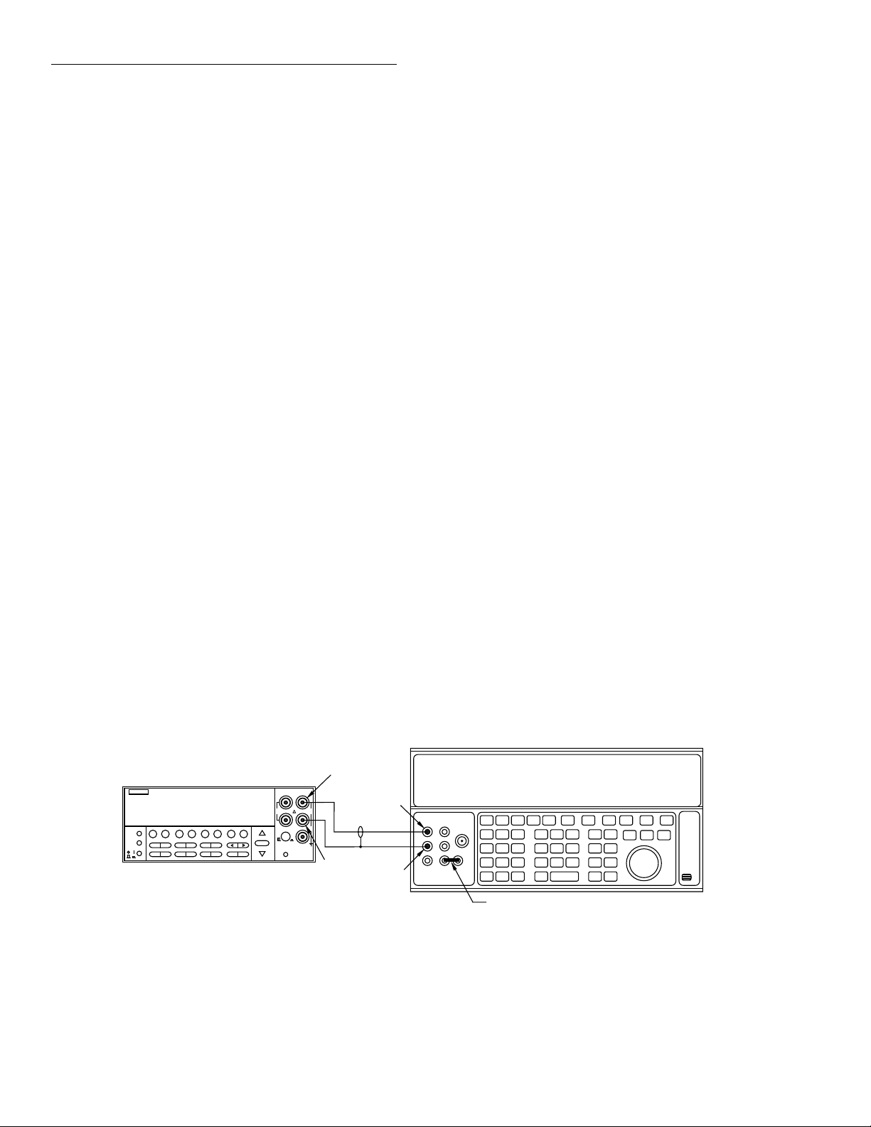
Calibration
26. Press ENTER, and note that the instrument displays the
following during 1M¾ calibration:
Performing 1.0 MOhm Calibration
27. At this point, the instrument will display the following
message advising you to disconnect test leads:
OPEN CIRCUIT INPUTS
28. Disconnect all test leads from the INPUT and SENSE
jacks, then press ENTER. During this calibration phase,
the instrument will display the following:
Performing Open-Ckt Calibration
29. After open circuit calibration, the instrument will display the following message:
AC CALIBRATION PHASE
30. Make sure all test leads are still disconnected from the
Model 2001 INPUT and SENSE jacks.
31. Press ENTER to perform AC calibration, which will
take a while to complete. During AC calibration, the instrument will display the following:
Calibrating AC: Please wait
32. After the AC calibration phase is completed, the instrument will display the following:
AC CAL COMPLETE
34. Connect the calibrator to the INPUT terminals, as
shown in Figure 2-3.
35. Press ENTER. The instrument will display the following:
Connect 20V @ 1kHz
36. Set the calibrator to output 20V AC at a frequency of
1kHz, then press ENTER. The instrument will display
the following:
Low-Level Cal - Step 1 of 15
37. Next, the instrument will prompt for a new calibration
signal:
Connect 20V @ 30kHz
38. Program the calibrator for an output voltage of 20V AC
at 30kHz, then press ENTER. The instrument will display the following while calibrating this step:
Low-Level Cal - Step 2 of 15
39. The Model 2001 will then display:
Connect 200V @ 1kHz
40. Set the calibrator output to 200V AC at a frequency of
1kHz, then press ENTER. The Model 2001 will display
the following message:
Low-Level Cal - Step 3 of 15
33. Press ENTER. The instrument will display the following to indicate the start of the low-level calibration
phase:
LOW-LEVEL CAL PHASE
NOTE
Use the exact calibration values shown
when performing the following steps.
Model 2001
PREV
DCV ACV DCI ACI Ω2 Ω4
DISPLAY
NEXT
REL TRIG STORE RECALL
POWER
INFO LOCAL CHAN SCAN CONFIG MENU EXIT ENTER
FILTER MATH
Figure 2-3
Calibration voltage connections
2001 MULTIMETER
FREQ TEMP
SENSE
Ω 4 WIRE
350V
PEAK
INPUTS
F
RANGE
FRONT/REAR
AUTO
RANGE
CAL
Input HI
INPUT
HI
1100V
PEAK
LO
500V
PEAK
R
2A 250V
AMPS
Output HI
Input
LO
Output
LO
Note: Use internal Guard (EX GRD LED is off).
41. When finished with this step, the Model 2001 will display:
Connect 200V @ 30kHz
42. Set the calibrator output to 200V AC at 30kHz, then
press ENTER. The Model 2001 will display the following:
Low-Level Cal - Step 4 of 15
5700A Calibrator
Ground link installed.
2-16
Page 46

Calibration
43. The unit will then prompt for the next calibration signal:
Connect 1.5V @ 1kHz
44. Set the calibrator for 1.5V AC at a frequency of 1kHz,
then press ENTER. The Model 2001 will display the
following:
Low-Level Cal - Step 5 of 15
45. After step 5, the unit will display the following:
Connect 200mV @ 1kHz
46. Program the calibrator to output 200mV at a frequency
of 1kHz, then press ENTER. The Model 2001 will then
display the following:
Low-Level Cal - Step 6 of 15
47. When finished with step 6, the unit will display the following:
Connect 5mV @ 100kHz
48. Set the calibrator to output 5mV at a frequency of
100kHz, then press ENTER. The Model 2001 will then
display the following while calibrating:
Low-Level Cal - Step 7 of 15
49. Following step 7, the instrument will display the following message to prompt for the next calibration signal:
Connect 0.5mV @ 1kHz
50. Program the calibrator to output 0.5mV at 1kHz, then
press ENTER. The unit will display the following inprogress message:
Low-Level Cal - Step 8 of 15
52. Set the calibrator to output +2V DC, then press the ENTER key. The Model 2001 will advise you that the
present step is in progress:
Low-Level Cal - Step 9 of 15
53. After this step has been completed, the unit will display
the following:
Connect -2 VDC
54. Set the calibrator for an output voltage of -2V DC, then
press ENTER. The Model 2001 will display the following message:
Low-Level Cal - Step 10 of 15
55. The Model 2001 will then prompt for the next calibration signal:
Set calibrator to 0V
56. Program the calibrator to output 0 VDC, then press the
ENTER key. The Model 2001 will display the following:
Low-Level Cal - Step 11 of 15
57. After completing step 11, the unit will display the following:
Connect 20mA @ 1kHz
58. Connect the calibrator to the AMPS and INPUT LO
jacks, as shown in Figure 2-4.
59. Set the calibrator output to 20mA AC at a frequency of
1kHz, then press the ENTER key. The Model 2001 will
display the following while calibrating:
Low-Level Cal - Step 12 of 15
51. Next, the unit will prompt for the next calibration signal:
Connect +2 VDC
Model 2001
PREV
DCV ACV DCI ACI Ω2 Ω4
DISPLAY
NEXT
REL TRIG STORE RECALL
POWER
INFO LOCAL CHAN SCAN CONFIG MENU EXIT ENTER
Figure 2-4
Current calibration connections
2001 MULTIMETER
FREQ TEMP
FILTER MATH
SENSE
Ω 4 WIRE
350V
PEAK
INPUTS
F
R
RANGE
FRONT/REAR
AUTO
RANGE
CAL
Input
INPUT
LO
HI
1100V
PEAK
LO
500V
PEAK
2A 250V
AMPS
Output HI
Amps
Output
LO
Note: Be sure calibrator is set for normal current output.
Use internal Guard (EX GRD LED is off).
60. The unit will then prompt for the next calibration signal:
Connect +0.2ADC
5700A Calibrator
Ground link installed.
2-17
Page 47
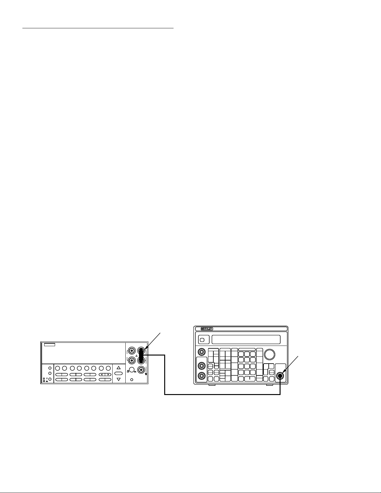
Calibration
61. Program the calibrator to output +200mA DC, then
press then ENTER key. The Model 2001 will display the
following while calibrating:
Low-Level Cal - Step 13 of 15
62. The Model 2001 will prompt for the next calibration signal:
Connect +2 ADC
63. Program the calibrator to output +2A DC, then press the
ENTER key. During calibration, the instrument will display the following:
Low-Level Cal - Step 14 of 15
64. The unit will then prompt for the last calibration signal:
Connect 2 V at 1 Hz
65. Put the calibrator in standby, then disconnect it from the
Model 2001 INPUT and AMPS jacks; connect the synthesizer to INPUT HI and LO, as shown in Figure 2-5.
66. Set synthesizer operation modes as follows:
FCTN: sine
FREQ: 1Hz
AMPTD: 2Vrms
MODE: CONT
67. Press the Model 2001 ENTER key. The instrument will
display the following while calibrating:
Low-Level Cal - Step 15 of 15
68. After step 15 is completed, the instrument will display
the following message to indicate that calibration has
been completed:
CALIBRATION COMPLETE
69. Press ENTER. The instrument will prompt you to enter
the calibration date:
CAL DATE: 01/01/92
70. Use the cursor and range keys to set the date as desired,
then press ENTER. Press ENTER a second time to confirm your date selection.
71. The Model 2001 will then prompt you to enter the calibration due date:
NEXT CAL: 01/01/92
72. Use the cursor keys to set the date as desired, then press
ENTER. Press ENTER again to confirm your date.
73. The Model 2001 will then display the following message:
CALIBRATION SUCCESS
74. If you wish to save the new calibration constants, press
ENTER. If, on the other hand, you wish to restore previous calibration constants, press EXIT.
75. Press EXIT as necessary to return to normal display.
NOTE
Calibration will be locked out automatically when the calibration procedure is
completed.
2.10.4 IEEE-488 bus low-level calibration
procedure
Follow the steps below to perform low-level calibration over
the IEEE-488 bus. Table 2-7 summarizes calibration commands for the procedure.
Model 2001
PREV
DCV ACV DCI ACI Ω2 Ω4 FREQ TEMP
DISPLAY
NEXT
REL TRIG STORE RECALL
POWER
INFO LOCAL CHAN SCAN CONFIG MENU EXIT ENTER
Figure 2-5
Synthesizer connections
2-18
FILTER MATH
2001 MULTIMETER
RANGE
AUTO
RANGE
BNC-to-Dual
Banana Plug
Model 3930A Synthesizer
3930A MULTIFUNCTION SYNTHESIZER
Adapter
SENSE
INPUT
Ω 4 WIRE
HI
350V
1100V
PEAK
PEAK
LO
500V
INPUTS
PEAK
F
R
FRONT/REAR
2A 250V
AMPS
CAL
Function
Output
50Ω BNC Coaxial Cable
Page 48

Calibration
Procedure
1. Connect the Model 2001 to the IEEE-488 bus of the
computer using a shielded IEEE-488 cable such as the
Keithley Model 7007.
2. Make sure the primary address of the Model 2001 is the
same as the address specified in the program you will be
using to send commands (see paragraph 2.6.3).
3. Turn off the power if the instrument is presently turned
on.
4. Press and hold the recessed CAL switch while turning
on the power. The instrument will display the following
message to indicate it is ready for the low-level calibration procedure:
MANUFACTURING CAL
5. Allow the Model 2001 to warm up for at least one hour
before performing calibration.
6. Connect the Model 8610 low-thermal short to the instrument INPUT and SENSE terminals, as shown in Figure
2-1. Wait three minutes before proceeding to allow for
thermal equilibrium.
NOTE
Be sure to properly connect HI, LO, and
SENSE terminals. Keep drafts away from
low-thermal connections to avoid thermal
drift, which could affect calibration accuracy.
7. Send the following command over the bus:
:CAL:PROT:DC:ZERO
Wait until the Model 2001 finishes this calibration step
before proceeding. (You can use the *OPC or *OPC?
commands to determine when calibration steps end, as
discussed in paragraph 3.6.)
8. Disconnect the low-thermal short, and connect the DC
calibrator to the INPUT jacks, as shown in Figure 2-2.
9. Set the DC calibrator output to +2.00000V, and turn external sense off. Send the following command to the
Model 2001 over the IEEE-488 bus:
:CAL:PROT:DC:LOW 2.0
(Be sure to use the exact calibration value if you are using a voltage other than 2V. The allowable range is
0.98V to 2.1V).
NOTE
For best results, use the calibration values
given in this part of the procedure whenever possible.
Wait until the Model 2001 finishes this step before going
on.
10. Set the DC calibrator output to +20.00000V. Send the
following command to the instrument:
:CAL:PROT:DC:HIGH 20
(Send the actual calibration value in the range of 9.8V to
21V if you are using a different voltage.) Wait until the
Model 2001 finishes this step before going on.
11. Set the calibrator output to 19.0000k¾, and turn external
sense on. Send the following command to the Model
2001:
:CAL:PROT:DC:LOHM <value>
Here, <value> is the actual calibrator resistance value.
For example, if the calibrator resistance is 18.9987k¾,
the command would appear as follows:
:CAL:PROT:DC:LOHM 18.9987E3
Wait until the Model 2001 finishes the 20k¾ calibration
step before continuing.
NOTE
If your calibrator can source 20k¾, use
that value instead of the 19k¾ value used
here.
12. Set the calibrator output to 1.0000M¾, and turn external
sense off. Send the following command to the Model
2001:
:CAL:PROT:DC:HOHM <value>
Here, <value> is the actual calibrator resistance value.
For example, if the calibrator resistance is 1.00023M¾,
the command would appear as follows:
:CAL:PROT:DC:HOHM 1.00023E6
Wait until the Model 2001 finishes 1M¾ calibration before continuing.
13. Disconnect all test leads from the INPUT and SENSE
jacks. Send the following command to the instrument:
:CAL:PROT:DC:OPEN
Wait until the open-circuit calibration is complete before going on to the next step.
14. To program the Model 2001 to calculate new calibration
constants, send the following command over the bus:
:CAL:PROT:DC:CALC
15. Check for DC calibration errors by sending the following query:
:SYST:ERR?
2-19
Page 49

Calibration
16. Perform user AC calibration by sending the following
command:
:CAL:UNPR:ACC
Note that the AC calibration phase will take about six
minutes to complete.
17. Check for AC calibration errors by sending the following command:
:SYST:ERR?
NOTE
The following steps perform the low-level
part of the calibration procedure. Use only
the indicated calibration values for these
steps. Be sure the instrument completes
each step before sending the next calibration command.
18. Connect the Model 2001 to the calibrator using 2-wire
connections, as shown in Figure 2-3.
19. Program the calibrator to output 20V AC at a frequency
of 1kHz, then send the following command to the Model
2001:
:CAL:PROT:LLEV:STEP 1
20. Program the calibrator to output 20V AC at a frequency
of 30kHz, and send the following command to the Model 2001:
:CAL:PROT:LLEV:STEP 2
21. Set the calibrator output to 200V AC at 1kHz, then send
the following command:
:CAL:PROT:LLEV:STEP 3
22. Set the calibrator output to 200V AC at a frequency of
30kHz, then send the following command:
:CAL:PROT:LLEV:STEP 4
23. Program the calibrator to output 1.5V AC at a frequency
of 1kHz. Send the following command to the Model
2001:
:CAL:PROT:LLEV:STEP 5
24. Program the calibrator to output 200mV AC at a frequency of 1kHz, and send the following command to the
Model 2001:
:CAL:PROT:LLEV:STEP 6
25. Set the calibrator output to 5mV AC at a frequency of
100kHz. Send the following command to the Model
2001:
:CAL:PROT:LLEV:STEP 7
26. Program the calibrator to output 0.5mV AC at a frequency of 1kHz. Send the following command to the Model
2001:
:CAL:PROT:LLEV:STEP 8
27. Set the calibrator output to +2V DC. Send the following
command to the Model 2001:
:CAL:PROT:LLEV:STEP 9
28. Program the calibrator to output -2V DC, and send the
following command to the Model 2001:
:CAL:PROT:LLEV:STEP 10
29. Set the calibrator output to 0V DC, and then send the
following command:
:CAL:PROT:LLEV:STEP 11
30. Connect the calibrator to the AMPS and INPUT LO terminals, as shown in Figure 2-4.
31. Program the calibrator to output 20mA AC at a frequency of 1kHz. Send the following command to the Model
2001:
:CAL:PROT:LLEV:STEP 12
32. Set the calibrator output to +200mA DC. Send the following command to the Model 2001:
:CAL:PROT:LLEV:STEP 13
33. Program the calibrator to output +2A DC, then send the
following command to the Model 2001:
:CAL:PROT:LLEV:STEP 14
34. Connect the multifunction synthesizer to the Model
2001, as shown in Figure 2-5.
35. Set the synthesizer operating modes as follows:
FCTN: sine
FREQ: 1Hz
AMPTD: 2Vrms
MODE: CONT
36. Send the following command to the Model 2001:
:CAL:PROT:LLEV:STEP 15
37. Calculate new calibration constants by sending the following command to the Model 2001:
:CAL:PROT:LLEV:CALC
38. To check for calibration errors, send the following query:
:SYST:ERR?
If no errors are reported, calibration was successfully
completed.
2-20
Page 50

Calibration
39. Update the calibration date and calibration due date by
sending the following commands:
:CAL:PROT:DATE ‘1/01/92’
:CAL:PROT:NDUE ‘1/01/93’
40. Save calibration constants in EEPROM by sending the
following command:
:CAL:PROT:SAVE
41. Finally, lock out calibration by sending the following
command:
:CAL:PROT:LOCK
2-21
Page 51

3
Calibration Command Reference
3.1 Introduction
This section contains detailed information on the various
Model 2001 IEEE-488 bus calibration commands. Section 2
of this manual covers detailed calibration procedures, and
Appendix B lists several calibration programs. For information on additional commands to control other instrument
functions, refer to the Model 2001 Operator’s Manual.
Information in this section includes:
3.2 Command summary: Summarizes all commands necessary to perform comprehensive, AC, and low-level
calibration.
3.3 CALibration:PROTected subsystem: Gives detailed
explanations of the various commands used for both
comprehensive and low-level calibration.
3.4 CALibration:UNPRotected subsystem: Discusses the
:ACC command, which is used to perform AC user calibration over the bus.
3.5 Bus error reporting: Summarizes bus calibration errors, and discusses how to obtain error information.
3.6 Detecting calibration step completion: Covers how to
determine when each calibration step is completed by
using the *OPC and *OPC? commands.
3.2 Command summary
Table 3-1 summarizes Model 2001 calibration commands
along with the paragraph number where a detail description
of each command is located.
3-1
Page 52

Calibration Command Reference
Table 3-1
IEEE-488 bus calibration command summary
Command Description Paragraph
:CALibration
:PROTected
:LOCK
:SWITch?
:SAVE
:DATA?
:DATE “<string>”
:DATE?
:NDUE “<string>”
:NDUE?
:LLEVel
:SWITch?
Calibration root command.
All commands in this subsystem are protected by the CAL switch.
Lock out calibration (opposite of enabling cal with CAL switch).
Request comprehensive CAL switch state. (0 = locked; 1 = unlocked)
Save cal constants to EEPROM.
Download cal constants from 2001.
Send cal date to 2001.
Request cal date from 2001.
Send next due cal date to 2001.
Request next due cal date from 2001.
Low-level calibration subsystem.
Request low-level CAL switch state. (0 = locked; 1 = unlocked)
3.3
3.3.1
3.3.2
3.3.3
3.3.4
3.3.5
3.3.6
3.3.7
3.3.8
3.3.9
:STEP <Step #>
1
2
3
4
5
6
7
8
9
10
11
12
13
14
15
:STEP?
:CALCulate
:DC
:ZERO
:LOW <value>
:HIGH <value>
:LOHM <value>
:HOHM <value>
:OPEN
:CALCulate
:UNPRotected
:ACCompensation
NOTE: Upper case letters indicate short form of each command. For example, instead of sending “:CALIBRATION:PROTECTED:LOCK”, you can send
“:CAL:PROT:LOCK”.
20V AC at 1kHz step.
20V AC at 30kHz step.
200V AC at 1kHz step.
200V AC at 30kHz step.
1.5V AC at 1kHz step.
0.2V AC at 1kHz step.
5mV AC at 100kHz step.
0.5mV AC at 1kHz step.
+2V DC step.
-2V DC step.
0V DC step.
20mA AC at 1kHz step.
+0.2A DC step.
+2A DC step.
2V AC at 1Hz step.
Request cal step number.
Calculate low-level cal constants.
User calibration subsystem.
Low-thermal short calibration step.
+2V DC calibration step.
+20V DC calibration step.
20k¾ calibration step.
1M¾ calibration step.
Open circuit calibration step.
Calculate DC cal constants.
All commands in this subsystem are not protected by CAL switch.
Perform user AC calibration (disconnect all cables)
3.3.10
3.4
3.4.1
3-2
Page 53

Calibration Command Reference
3.3 :CALibration:PROTected subsystem
The protected calibration subsystem commands perform all Model 2001 calibration except
for AC-only calibration. All commands in this subsystem are protected by the calibration
lock (CAL switch). The following paragraphs discuss these commands in detail.
3.3.1 :LOCK
(:CALibration:PROTected):LOCK
Purpose To lock out comprehensive and low-level calibration commands once calibration has been
completed.
Format :cal:prot:lock
Parameters None
Description The :LOCK command allows you to lock out both comprehensive and low-level calibration
after completing those procedures. Thus, :LOCK does just the opposite of pressing in on
the front panel CAL switch to unlock calibration.
Programming note To unlock comprehensive calibration, press in on the CAL switch with power turned on. To
unlock low-level calibration, hold in the CAL switch while turning on the power.
Programming example 10 OUTPUT 716; “:CAL:PROT:LOCK” ! Lock out calibration.
3.3.2 :SWITch?
(:CALibration:PROTected):SWITch?
Purpose To read comprehensive calibration lock status.
Format :cal:prot:swit?
Response 0 Comprehensive calibration locked.
1 Comprehensive calibration unlocked.
Description The :SWITch? query requests status from the Model 2001 on calibration locked/unlocked
state. Calibration must be unlocked by pressing in on the CAL switch while power is turned
on before calibration can be performed.
Programming note The :CAL:PROT:SWIT? query does not check the status of the low-level calibration lock,
which can be checked by using the :CAL:PROT:LLEV:SWIT? query. (See paragraph
3.3.9.)
Programming example 10 OUTPUT 716; “:CAL:PROT:SWIT?” ! Query for switch status.
20 ENTER 716; S ! Input response.
30 PRINT S ! Display response.
3-3
Page 54

Calibration Command Reference
3.3.3 :SAVE
(:CALibration:PROTected):SAVE
Purpose To save calibration constants in EEPROM after the calibration procedure.
Format :cal:prot:save
Parameters None
Description The :SAVE command stores internally calculated calibration constants derived during cal-
ibration in EEPROM. EEPROM is non-volatile memory, and calibration constants will be
retained indefinitely once saved. Generally, :SAVE is the last command sent during calibration.
Programming note Calibration will be only temporary unless the :SAVE command is sent to permanently store
calibration constants.
Programming example 10 OUTPUT 716; “:CAL:PROT:SAVE” ! Save constants.
3.3.4 :DATA?
(:CALibration:PROTected):DATA?
Purpose To download calibration constants from the Model 2001
Format :cal:prot:data?
Response <Cal 1>,<Cal 2>,...<Cal n>
Description :DATA? allows you to request the present calibration constants stored in EEPROM from the
instrument. This command can be used to compare present constants with those from a previous calibration procedure to verify that calibration was performed properly. The returned
values are 99 numbers using ASCII representation delimited by commas (,). See Appendix
C for a listing of constants.
Programming note The :CAL:PROT:DATA? response is not affected by the FORMAT subsystem.
Programming example 10 DIM A$[2000] ! Dimension string.
20 OUTPUT 716; “:CAL:PROT:DATA?” ! Request constants.
30 ENTER 716; A$ ! Input constants.
40 PRINT A$ ! Display constants.
3-4
Page 55

Calibration Command Reference
3.3.5 :DATE
(:CALibration:PROTected):DATE
Purpose To send the calibration date to the instrument.
Format :cal:prot:date “<string>”?
Parameters <string> = date (mm/dd/yy)
Description The :DATE command allows you to store the calibration date in instrument memory for fu-
ture reference. You can read back the date from the instrument over the bus by using the
:DATE? query, or by using the CALIBRATION selection in the front panel menu.
Programming note The date <string> must be enclosed either in double or single quotes (“<string>” or
‘<string>’).
Programming example 10 OUTPUT 716; “:CAL:PROT:DATE ‘01/01/92’” ! Send date.
3.3.6 :DATE?
(:CALibration:PROTected):DATE?
Purpose To request the calibration date from the instrument.
Format :cal:prot:date?
Response <date> (mm/dd/yy)
Description The :DATE? query allows you to request from the instrument the previously stored calibra-
tion date. The instrument response is simply a string of ASCII characters representing the
last stored date.
Programming example 10 OUTPUT 716; “:CAL:PROT:DATE?” ! Query for date.
20 ENTER 716; A$ ! Input date.
30 PRINT A$ ! Display date.
3.3.7 :NDUE
(:CALibration:PROTected):NDUE
Purpose To send the next calibration due date to the instrument.
Format :cal:prot:ndue “<string>”
Parameters <string> = next due date (mm/dd/yy)
Description The :NDUE command allows you to store the date when calibration is next due in instru-
ment memory. You can read back the next due date from the instrument over the bus by using the :NDUE? query, or by using the CALIBRATION-DATES selection in the front panel
menu.
Programming note The next due date <string> must be enclosed either in single or double quotes (“<string>”
or ‘<string>’).
Programming example 10 OUTPUT 716; “:CAL:PROT:NDUE ‘01/01/93’” ! Send due date.
3-5
Page 56

Calibration Command Reference
3.3.8 :NDUE?
(:CALibration:PROTected):NDUE?
Purpose To request the calibration due date from the instrument.
Format :cal:prot:ndue?
Response <date> (mm/dd/yy)
Description The :NDUE? query allows you to request from the instrument the previously stored cali-
bration due date. The instrument response is a string of ASCII characters representing the
last stored due date.
Programming example 10 OUTPUT 716; “:CAL:PROT:DATE?” ! Query for due date.
20 ENTER 716; A$ ! Input due date.
30 PRINT A$ ! Display due date.
3.3.9 :LLEVel
(CALibration:PROTected):LLEVel
Low-level calibration commands are summarized in Table 3-2.
Table 3-2
Low-level calibration commands
Command Description
:CALibration
:PROTected
:LLEVel
:SWITch?
:STEP <Step #>
1
2
3
4
5
6
7
8
9
10
11
12
13
14
15
:CALCulate
Low-level calibration subsystem.
Request low-level CAL switch state.
(0 = locked; 1 = unlocked)
20V AC at 1kHz step.
20V AC at 30kHz step.
200V AC at 1kHz step.
200V AC at 30kHz step.
1.5V AC at 1kHz step.
0.2V AC at 1kHz step.
5mV AC at 100kHz step
0.5mV AC at 1kHz step.
+2V DC step.
-2V DC step.
0V DC step.
20mA AC at 1kHz step.
+0.2A DC step.
+2A DC step.
2V AC at 1Hz step.
Calculate low-level cal constants.
3-6
Page 57

Calibration Command Reference
:SWITch?
(CALibration:PROTected:LLEVel):SWITch?
Purpose To request the state of the low-level calibration lock.
Format :cal:prot:llev:swit?
Response 0 Low-level calibration locked.
1 Low-level calibration unlocked.
Description :SWITch? query requests the status of the low-level calibration lock from the instrument.
This :SWITch? query should not be confused with the :SWITch query that requests the status of the comprehensive calibration lock (see paragraph 3.3.1).
Programming note To unlock low-level calibration, hold in the CAL switch while turning on instrument power.
Programming example 10 OUTPUT 716; “:CAL:PROT:LLEV:SWIT?” ! Request switch status.
20 ENTER 716; S ! Input switch status.
30 PRINT S ! Display switch status.
:STEP
(CALibration:PROTected:LLEVel):STEP
Purpose To program individual low-level calibration steps.
Format :cal:prot:llev:step <n>
Parameters 120V AC @ 1kHz
2 20V AC @ 30kHz
3 200V AC @ 1kHz
4 200V AC @ 30kHz
5 1.5V AC @ 1kHz
6200mV AC @ 1kHz
7 5mV AC @ 100kHz
8 0.5mV AC @ 1kHz
9+2V DC
10 -2V DC
11 0V DC
12 20mA @ 1kHz
13 +200mA DC
14 +2A DC
15 2V AC @ 1Hz
Description The :STEP command programs the 15 individual low-level calibration steps; <n> repre-
sents the calibration step number. The appropriate signal must be connected to the instrument when programming each step, as summarized in the parameters listed above (see
Section 2 for details).
Programming example 10 OUTPUT 716; “:CAL:PROT:LLEV:STEP 1” ! Low-level Step 1.
3-7
Page 58

Calibration Command Reference
Purpose To request current low-level calibration step.
Format :cal:prot:llev:step?
Response 1 20V AC @ 1kHz
:STEP?
(CALibration:PROTected:LLEVel):STEP?
2 20V AC @ 30kHz
3 200V AC @ 1kHz
4 200V AC @ 30kHz
5 1.5V AC @ 1kHz
6 200mV AC @ 1kHz
7 5mV AC @ 100kHz
8 0.5mV AC @ 1kHz
9+2V DC
10 -2V DC
11 0V DC
12 20mA @ 1kHz
13 +200mA DC
14 +2A DC
15 2V AC @ 1Hz
Description The :STEP? query requests the present low-level calibration step.
Programming example 10 OUTPUT 716; “:CAL:PROT:LLEV:STEP ?” ! Request step.
20 ENTER 716;S ! Input step.
30 PRINT S ! Display step.
:CALCulate
(:CALibration:PROTected:LLEVel):CALCulate
Purpose To program the Model 2001 to calculate new low-level calibration constants.
Format :cal:prot:llev:calc
Parameters None
Description The :CALCulate command causes the Model 2001 to calculate new low-level calibration
constants based on parameters determined during the calibration procedure. This command
should be sent after completing all low-level calibration steps, but before saving calibration
constants in EEPROM with the :SAVE command.
Programming example 10 OUTPUT 716; “:CAL:PROT:LLEV:CALC” ! Calculate constants.
3-8
Page 59

3.3.10 :DC
(CALibration:PROTected):DC
The :DC commands perform comprehensive (user) calibration. Table 3-3 summarizes these
comprehensive calibration commands.
Table 3-3
Comprehensive calibration commands
Command Description
:CALibration
:PROTected
:DC
:ZERO
:LOW <value>
:HIGH <value>
:LOHM <value>
:HOHM <value>
:OPEN
Calculate
Calibration Command Reference
User calibration subsystem.
Low-thermal short calibration step.
+2V DC calibration step.
+20V DC calibration step.
20k¾ calibration step.
1M¾ calibration step.
Open circuit calibration step.
DC cal constants.
:ZERO
(:CALibration:PROTected:DC):ZERO
Purpose To perform short-circuit comprehensive calibration.
Format :cal:prot:dc:zero
Parameters None
Description :ZERO performs the short-circuit calibration step in the comprehensive calibration proce-
dure. A low-thermal short (Model 8610) must be connected to the input jacks before sending this command.
Programming example 10 OUTPUT 716; “CAL:PROT:DC:ZERO” ! Do short-circuit cal.
:LOW
(:CALibration:PROTected:DC):LOW
Purpose To program the +2V DC comprehensive calibration step.
Format :cal:prot:dc:low <cal_voltage>
Parameters <Cal_voltage> = 1.0 to 2.0 [V]
Description :LOW programs the +2V DC comprehensive calibration step. The allowable range of the
calibration voltage parameter is from 1.0 to 2.0V, but 2V is recommended for best results.
Programming example 10 OUTPUT 716; “:CAL:PROT:DC:LOW 2” ! Program 2V step.
3-9
Page 60

Calibration Command Reference
:HIGH
(:CALibration:PROTected:DC):HIGH
Purpose To program the +20V DC comprehensive calibration step.
Format :cal:prot:dc:high <cal_voltage>
Parameters <Cal_voltage> = 10 to 20 [V]
Description :HIGH programs the +20V DC comprehensive calibration step. The allowable range of the
calibration voltage parameter is from 10 to 20V, but 20V is recommended for best results.
Programming example 10 OUTPUT 716; “:CAL:PROT:DC:HIGH 20” ! Program 20V step.
:LOHM
(CALibration:PROTected:DC):LOHM
Purpose To program the 20k¾ comprehensive calibration step.
Format :cal:prot:dc:lohm <cal_resistance>
Parameters <Cal_resistance> = 9E3 to 20E3 [¾]
Description :LOHM programs the 20k¾ comprehensive calibration step. The allowable range of the
calibration resistance parameter is from 9k¾ to 20k¾ (9E3 to 20E3). Use the 20k¾ value
whenever possible, or the closest possible value (for example, 19k¾, which is the closest
value available on many calibrators).
Programming example 10 OUTPUT 716; “:CAL:PROT:DC:LOHM 19E3”! Program 19k¾.
:HOHM
(CALibration:PROTected:DC):HOHM
Purpose To program the 1M¾ comprehensive calibration step.
Format :cal:prot:dc:hohm <cal_resistance>
Parameters <Cal_resistance> = 800E3 to 2E6 [¾]
Description :LOHM programs the 1M¾ comprehensive calibration step. The resistance parameter can
be programmed for any value from 800k¾ (800E3) to 2M¾ (2E6). Use the 1M¾ value
whenever possible, or the closest possible value on your calibrator for best results.
Programming example 10 OUTPUT 716; “:CAL:PROT:DC:HOHM 1E6” ! Program 1M¾ step.
3-10
Page 61

Calibration Command Reference
:CALCulate
(:CALibration:PROTected:DC):CALCulate
Purpose To program the Model 2001 to calculate new comprehensive calibration DC constants.
Format :cal:prot:dc:calc
Parameters None
Description The :CALCulate command should be sent to the instrument after performing all other DC
calibration steps to calculate new comprehensive calibration constants. All other comprehensive calibration steps must be completed before sending this command.
Programming example 10 OUTPUT 716; “:CAL:PROT:DC:CALC” ! Calculate new constants.
3-11
Page 62

Calibration Command Reference
3.4 :CALibration:UNPRotected Subsystem
3.3.11 :ACCompensation
(:CALibration:UNPRotected):ACCompensation
Purpose To perform user AC calibration.
Format :cal:unpr:acc
Parameters None
Description The :ACC command performs user AC calibration, which requires no calibration equip-
ment. All test leads must be disconnected from the input jacks when performing user AC
calibration.
Programming note Calibration constants generated by using the :ACC command are not stored in EEPROM.
Thus, AC calibration constants are in effect only until the instrument is turned off. In order
to save AC calibration constants, perform the comprehensive calibration procedure, and use
the :SAVE command.
Programming example 10 OUTPUT 716; “:CAL:UNPR:ACC: ! Perform AC user cal.
3-12
Page 63

Calibration Command Reference
3.5 Bus error reporting
3.5.1 Calibration error summary
Table 3-4 summarizes errors that may occur during bus calibration.
NOTE
See Appendix C for a complete listing of
calibration error messages.
3.5.2 Detecting calibration errors
Several methods to detect calibration errors are discussed in
the following paragraphs.
Error Queue
As with other Model 2001 errors, any calibration errors will
be reported in the bus error queue. You can read this queue
by using the :SYST:ERR? query. The Model 2001 will respond with the appropriate error message, as summarized in
Table 3-4.
Status Byte EAV (Error Available) Bit
Whenever an error is available in the error queue, the EAV
(Error Available) bit (bit 2) of the status byte will be set. Use
the *STB? query or serial polling to obtain the status byte,
then test bit 2 to see if it is set. If the EAV bit is set, an error
has occurred, and you can use the :SYST:ERR? query to read
the error and at the same time clear the EAV bit in the status
byte.
Generating an SRQ on Error
To program the instrument to generate an SRQ when an error
occurs, send the following command: *SRE 4. This command will enable SRQ when the EAV bit is set. You can then
read the status byte and error queue as outlined above to
check for errors and to determine the exact nature of the error.
3.6 Detecting calibration step completion
When sending calibration commands over the IEEE-488 bus,
you must wait until the instrument completes the current operation before sending a command. You can use either
*OPC? or *OPC to help determine when each calibration
step is completed. (The example program in paragraph 2.6.2
uses the *OPC command to detect when each calibration
step is completed.)
3.6.1 Using the *OPC? query
With the *OPC? (operation complete) query, the instrument
will place an ASCII 1 in the output queue when it has completed each step. In order to determine when the OPC response is ready, do the following:
1. Repeatedly test the MAV (Message Available) bit (bit 4)
in the status byte and wait until it is set. (You can request
the status byte by using the *STB? query or serial polling.)
2. When MAV is set, a message is available in the output
queue, and you can read the output queue and test for an
ASCII 1.
Table 3-4
Calibration error summary
Error Description
0, “No Error”
-102, “Syntax error”
-113, “Command header error”
-200, “Execution error”
-221, “Settings conflict”
-222, “Parameter data out of range”
+438, “Date of calibration not set”
+439, “Next date of calibration not set”
+440, “Calibration process not completed”
NOTE: This table lists only those errors that could occur because of some external problem such as improper connections or wrong
procedure. See Appendix C for a complete listing of all error messages.
No error present in error queue.
Calibration command syntax error.
Invalid calibration command header.
Cal commands sent out of sequence.
Cal command sent with calibration locked.
Calibration parameter invalid.
No calibration date sent.
No next calibration date sent.
Incomplete calibration procedure.
3-13
Page 64

Calibration Command Reference
3. After reading the output queue, repeatedly test MAV
again until it clears. At this point, the calibration step is
completed.
3.6.2 Using the *OPC command
The *OPC (operation complete) command can also be used
to detect the completion of each calibration step. In order to
use OPC to detect the end of each calibration step, you must
do the following:
1. Enable operation complete by sending *ESE 1. The
command sets the OPC (operation complete bit) in the
standard event enable register, allowing operation complete status from the standard event status register to set
the ESB (event summary bit) in the status byte when operation complete is detected.
2. Send the *OPC command immediately following each
calibration command. For example:
:CAL:PROT:DC:ZERO;*OPC
Note that you must include the semicolon (;) to separate
the two commands.
3. After sending a calibration command, repeatedly test
the ESB (Event Summary) bit (bit 5) in the status byte
until it is set. (Use either the *STB? query or serial polling to request the status byte.)
4. Once operation complete has been detected, clear OPC
status using one of two methods: (1) Use the *ESR?
query then read the response to clear the standard event
status register, or (2) Send the *CLS command to clear
the status registers. Note that sending *CLS will also
clear the error queue and operation complete status.
3-14
Page 65

A
Model 2001 Specifications
A-1
Page 66

Model 2001 Specifications
The following pages contain the complete specifications for the
2001. Every effort has been made to make these specifications
complete by characterizing its performance under the variety of
conditions often encountered in production, engineering and
research.
The 2001 provides 5-minute, 1-hour, 24-hour, 90-day, 1-year,
and 2-year specifications, with full specifications for the 90-day,
1-year and 2-year specifications. This allows the user to utilize
90-day, 1-year, or 2-year recommended calibration intervals,
depending upon the level of accuracy desired. As a general rule,
the 2001’s 2-year performance exceeds a 5
day, 180-day or 1-year specifications. 6
1
⁄2-digit DMM’s 90-
1
⁄2- or 71⁄2-digit performance
is assured using 90-day or 1-year specifications.
ABSOLUTE ACCURACY
To minimize confusion, all 90-day, 1-year and 2-year 2001
specifications are absolute accuracy, traceable to NIST based on
factory calibration. Higher accuracies are possible, based on
your calibration sources. For example, calibrating with a 10V
primary standard rather than a 20V calibrator will reduce
calibration uncertainty, and can thereby improve total 2001
accuracy for measurements up to 50% of range. Refer to the 2001
calibration procedure for details.
TYPICAL ACCURACIES
Accuracy can be specified as typical or warranted. All
specifications shown are warranted unless specifically noted.
Almost 99% of the 2001’s specifications are warranted specifications. In some cases it is not possible to obtain sources to
maintain traceability on the performance of every unit in
production on some measurements (e.g., high-voltage, highfrequency signal sources with sufficient accuracy do not exist).
Since these values cannot be verified in production, the values
are listed as typical.
2001 SPECIFIED CALIBRATION INTERVALS
MEASUREMENT 24 90 1 2
FUNCTION HOUR
DC Volts • • • •
DC Volts Peak Spikes •
AC Volts rms •
AC Volts Peak •
AC Volts Average •
AC Volts Crest Factor •
Ohms • • • •
DC Current • • • •
DC In-Circuit Current • • •
AC Current •
Frequency • • •
Temperature (Thermocouple) • • •
Temperature (RTD) • • •
1
For T
CAL
2
3
±1°C.
For T
CAL
±5°C.
For ±2°C of last AC self cal.
1
DAY2YEAR2YEAR
3
••
3
••
3
••
3
••
3
••
3
••
2
Page 67

DC VOLTS
DCV INPUT CHARACTERISTICS AND ACCURACY
RANGE SCALE LUTION LUTION RESISTANCE 5 Minutes
FULL RESO- RESO- INPUT
4
200mV
20 V
200 V
1000 V
2V
±
210.00000 10 nV 100 nV >10 G
±
2.1000000 100 nV 1 μV >10 G
±
21.000000 1 μV 10 μV >10 G
±
210.00000 10 μV 100 μV 10 MΩ±1% 2 + 1.5 13 + 3 27 + 3 38 + 3 52 + 3 4.3 +1
±
1100.0000 100 μV 1 mV 10 MΩ±1% 10 + 1.5 17 + 6 31 + 6 41 + 6 55 + 6 4.1 +1
DC VOLTAGE UNCERTAINTY =
DEFAULT ACCURACY
Ω
Ω
Ω
±
[ (ppm of reading) × (measured value) + (ppm of range) × (range used)] / 1,000,000.
±
12
3 + 3 10 + 6 25 + 6 37 + 6 50 + 6 3.3 + 1. 5
2 + 1.5 7 + 2 18 + 2 25 + 2 32 + 2 2.6 +0.15
2 + 1.5 7 + 4 18 + 4 24 + 4 32 + 4 2.6 +0 .7
% ACCURACY = (ppm accuracy) /10,000.
1PPM OF RANGE = 2 counts for ranges up to 200V, 1 count on 1000V range at 6
SPEED AND ACCURACY
5
90 Days
1
ACCURACY
±
(ppm of reading+ppm of range+ppm of range rms noise10)
1PLC
DFILT On, 1PLC 0.1PLC 0.01PLC
11
RANGE 10 Readings DFILT Off DFILT Off DFILT Off
4
200 mV
2 V 18+2+0 18+2+0.2 18+25+1 130+200+3
25+6+0 25+6+0.6 25+30+10 100+200+15
20 V 18+4+0 18+4+0.3 18+20+0.5 130+200+3
200 V 27+3+0 27+5+0.3 27+20+0.8 130+200+3
1000 V 31+6+0 31+6+0.1 31+21+0.5 90+200+2
PLC = power line cycle; DFILT = digital filter
DCV READING RATES
9,10
(ppm of reading + ppm of range)
24 Hours290 Days31 Year32 Years
⁄2 digits.
NOISE REJECTION (dB)
SPEED AC and DC CMRR
(Number of Line Sync On
Power Line Line Sync Internal 25-Reading On
Cycles) On7Trigger
NPLC = 10 140 120 9 0 80 60
NPLC
NPLC < 1 60 50 3 0 20 0
Effective noise is reduced by a factor of 10 for every 20dB of noise rejection (140dB
reduces effective noise by 10,000,000:1).
CMRR is rejection of undesirable AC or DC signal between LO and earth. NMRR
is rejection of undesirable AC signal between HI and LO.
1
6
8
≥
1 140 120 90 80 60
TEMPERATURE COEFFICIENT
±
(ppm of reading + ppm of range)/°C
3
Outside T
CAL
AC NMRR
7
Line Sync Internal
±5°
7
C
DFILT On DFILT Off DFILT Off
200mV, 2V, 200V Ranges
NPLC APERTURE BITS DIGITS Auto Zero Off Auto Zero On Auto Zero Off Auto Zero On Auto Zero Off Auto Zero On
10 167 ms (200 ms) 28 7
MEASUREMENT DEFAULT READINGS/SECOND TO MEMORY READINGS/SECOND TO IEEE-488 TIME STAMP TO IEEE-488
1
⁄
2 33.4 ms (40 ms) 26 7
1 16.7 ms (20 ms) 25 6
0.2 3.34 ms (4 ms) 22 6
0.1 1.67 ms (2 ms) 21 5
μ
0.02 334
0.01 167
11
0.01
s (400 μs) 19 51⁄
μ
s (167 μs) 16 41⁄
167 μs (167 μs) 16 41⁄
2
1
⁄
2
1
⁄
2
1
⁄
2
1
⁄
2
2
2
2
6 (5.1) 2 (1.7) 6 2 (1.6) 6 (4.1) 2 (1.6)
30 (25) 9 (7.6) 28 (23) 9 (7.3) 27 (22) 8 (7.2)
58 (48) 44 (34) 54 (45) 41 (32) 49 (41) 37 (30)
214 (186) 127 (112) 183 (162) 104 (101) 140 (126) 88 (85)
272 (272) 150 (148) 228 (225) 129 (123) 156 (153) 100 (96)
284 (287) 156 (155) 230 (230) 136 (134) 158 (156) 104 (103)
417 (417) 157 (157) 317 (317) 137 (134) 198 (198) 105 (103)
2000 (2000) 2000 (2000)
READINGS/SECOND WITH
20V, 1000V Ranges
10 167 ms (200 ms) 28 71⁄
2 33.4 ms (40 ms) 26 7
1 16.7 ms (20 ms) 25 6
0.2 3.34 ms (4 ms) 22 6
0.1 1.67 ms (2 ms) 21 5
μ
0.02 334
0.01 167
11
0.01
s (400 μs) 19 51⁄
μ
s (167 μs) 16 41⁄
167 μs (167 μs) 16 41⁄
2
1
⁄
2
1
⁄
2
1
⁄
2
1
⁄
2
2
2
2
6 (5.1) 2 (1.7) 6 2 (1.6) 6 2 (1.6)
30 (25) 9 (8.2) 28 (23) 9 (7.8) 27 (22) 9 (7.7)
57 (48) 42 (38) 54 (45) 43 (35) 48 (41) 39 (32)
201 (186) 102 (113) 173 (162) 102 (99) 129 (127) 84 (83)
201 (201) 126 (116) 175 (173) 105 (105) 129 (128) 86 (86)
227 (227) 129 (129) 178 (178) 114 (114) 138 (138) 90 (90)
422 (422) 130 (130) 333 (333) 117 (117) 199 (199) 95 (95)
2000 (2000) 2000 (2000)
Trigger
8
SETTLING CHARACTERISTICS: <500μs to 10ppm of step size. Reading settling
times are affected by source impedance and cable dielectric absorption
characteristics. Add 10ppm of range for first reading after range change.
REF
ZERO STABILITY: Typical variation in zero reading, 1 hour, T
±1°C, 61⁄2-digit
default resolution, 10-reading digital filter:
ZERO STABILITY
Range 1 Power Line Cycle Integration 10 Power Line Cycle Integration
2V – 1000V
200 mV
3 counts
±
5 counts
±
2 counts
±
3 counts
±
DC VOLTS NOTES
1. Specifications are for 1 power line cycle, Auto Zero on, 10-reading digital filter, except as
noted.
2. For T
CAL
±1°
which is 23
3. For T
US NIST.
4. When properly zeroed using REL function.
5. For T
same speed accuracy ppm changes to the 1-year or 2-year base accuracy.
6. Applies for 1k
7. For noise synchronous to the line frequency.
C, following 55-minute warm-up. TCAL is ambient temperature at calibration,
°
C from factory.
CAL
±5°
C, following 55-minute warm-up. Specifications include factory traceability to
CAL
±5°
C, 90-day accuracy. 1-year or 2-year accuracy can be found by applying the
Ω
imbalance in the LO lead. For 400Hz operation, subtract 10dB.
ISOLATED POLARITY REVERSAL ERROR: This is the portion of the instrument
error that is seen when high and low are reversed when driven by an isolated
source. This is not an additional error—it is included in the overall instrument
accuracy spec. Reversal Error: <2 counts at 10V input at 6
1
⁄2 digits, 10 power
line cycles, 10-reading digital filter.
°
INPUT BIAS CURRENT: <100pA at 25
C.
LINEARITY: <1ppm of range typical, <2ppm maximum.
AUTORANGING: Autoranges up at 105% of range, down at 10% of range.
±
8. For line frequency
9. See Operating Speed section for additional detail. For DELAY=0, internal trigger, digital
filter off, display off (or display in “hold” mode). Aperture is reciprocal of line frequency.
These rates are for 60Hz and (50Hz).
10.Typical values.
11.In burst mode, display off. Burst mode requires Auto Zero refresh (by changing
resolution or measurement function) once every 24 hours.
12.DCV Transfer Stability typical applications are standard cell comparisons and
relative accuracy measurements. Specs apply for 10 power line cycles, 20reading digital filter, autozero on with type synchronous, fixed range following
2-hour warm-up at full scale to 10% of full scale, at T
ambient temperature). Specifications on the 1000V range are for measurements
within 5% of the initial measurement value and following measurement settling.
0.1%.
REF
± 1°
C (TREF is the initial
Page 68

DCV PEAK SPIKES MEASUREMENT
REPETITIVE SPIKES ACCURACY190 Days, ±2°C from last AC self-cal±(% of reading+% of range)
1kHz– 10kHz– 30kHz– 50kHz– 100kHz– 300kHz– 500kHz– 750kHz–
4
RANGE 0–1kHz
10kHz 30kHz 50kHz 100kHz 300kHz 500kHz 750kHz 1MHz Outside T
200 mV 0.08+0.7 0.08+0.7 0.1 +0.7 0.15+0.7 0.25+0.7 1.0+0.7 2.5+0.7 5.5+0.7 9+0.7 0.002+0.03
2 V 0.08+0.3 0.08+0.3 0.1 +0.3 0.15+0.3 0.25+0.3 1.0+0.3 2.5+0.3 5.5+0.3 9+0.3 0.002+0.03
20 V 0.09+0.7 0.1 +0.7 0.12+0.7 0.17+0.7 0.25+0.7 1.0+0.7 2.5+0.7 5.5+0.7 9+0.7 0.004+0.03
3
200 V
1000 V
Max. % of Range
REPETITIVE SPIKES ACCURACY
RANGE 0–1kHz
200 mV 0.08+0.7 0.09+0.7 0.1 +0.7 0.15+0.7 0.25+0.7 1.0+0.7 2.5+0.7 5.5+0.7 9+0.7 0.002+0.03
2 V 0.08+0.3 0.09+0.3 0.1 +0.3 0.15+0.3 0.25+0.3 1.0+0.3 2.5+0.3 5.5+0.3 9+0.3 0.002+0.03
20 V 0.1 +0.7 0.11+0.7 0.14+0.7 0.19+0.7 0.25+0.7 1.0+0.7 2.5+0.7 5.5+0.7 9+0.7 0.004+0.03
200 V
1000 V
Max. % of Range
0.09+0.3 0.1 +0.3 0.12+0.3 0.17+0.3 0.25+0.3 1.0+0.322.5+0.325.5+0.329+0.3
3
0.1 +0.6 0.13+0.6 0.16+0.6 0.25+0.620.5 +0.6
±
125%
3
0.1 +0.3 0.11+0.3 0.14+0.3 0.19+0.3 0.25+0.3 1.0+0.322.5+0.325.5+0.329+0.3
3
0.12+0.6 0.16+0.6 0.2 +0.6 0.25+0.620.5 +0.6
±
125%
±
125%
1
1kHz– 10kHz– 30kHz– 50kHz– 100kHz– 300kHz– 500kHz– 750kHz–
4
10kHz 30kHz 50kHz 100kHz 300kHz 500kHz 750kHz 1MHz Outside T
±
125%
±
125%
1 or 2 Years, T
±
125%
±
125%
CAL
±5°C ±(% of reading+% of range)
±
125%
±
125%
±
125%
2
±
125%
2
±
125%
±
125%
±
125%
±
±
100%
100%
±
±
TEMPERATURE COEFFICIENT
±
(% of reading+% of range)/°C
2
75%
TEMPERATURE COEFFICIENT
±
(% of reading+% of range)/°C
2
75%
0.004+0.03
0.01 +0.02
0.004+0.03
0.01 +0.02
CAL
CAL
±2°C
±5°C
DEFAULT MEASUREMENT RESOLUTION: 31⁄2 digits.
±
MAXIMUM INPUT:
NON-REPETITIVE SPIKES: 10% of range per
SPIKE WIDTH: Specifications apply for spikes
1100V peak value, 2×10⁷V•Hz (for inputs above 20V).
μ
s typical slew rate.
≥1μ
s.
RANGE CONTROL: In Multiple Display mode, voltage range is the same as
DCV range.
SPIKES MEASUREMENT WINDOW: Default is 100ms per reading (settable from
0.1 to 9.9s in Primary Display mode).
INPUT CHARACTERISTICS: Same as ACV input characteristics.
SPIKES DISPLAY: Access as multiple display on DC Volts. First option presents
positive peak spikes and highest spike since reset. Second option presents
negative spikes and lowest spike. Highest and lowest spike can be reset by
pressing DCV function button. Third option displays the maximum and
minimum levels of the input signal. Spikes displays are also available
through CONFIG-ACV-ACTYPE as primary displays.
DCV PEAK SPIKES NOTES
1. Specifications apply for 10-reading digital filter. If no filter is used, add 0.25% of range
typical uncertainty.
2. Typical values.
3. Add 0.001% of reading × (V
4. Specifications assume AC+DC coupling for frequencies below 200Hz. Below 20Hz add
0.1% of reading additional uncertainty.
2
IN/100V)
additional uncertainty for inputs above 100V.
AC VOLTS
AC magnitude: RMS or Average. Peak and Crest Factor measurements also available.
ACV INPUT CHARACTERISTICS
RMS PEAK FULL SCALE DEFAULT
RANGE INPUT RMS RESOLUTION RESOLUTION INPUT IMPEDANCE Outside T
200 mV 1 V 210.0000 100 nV 1
μ
2 V 8V 2.100000 1
20 V 100 V 21.00000 10
200 V 800 V 210.0000 100
V 10 μV1M
μ
V 100 μV1M
μ
V 1 mV 1MΩ ±2% with <140pF 0.006 + 0.001
750 V 1100 V 775.000 1 mV 10 mV 1M
AC VOLTAGE UNCERTAINTY =
±
[ (% of reading) × (measured value) + (% of range ) × (range used) ] / 100.
μ
V1M
Ω ±
2% with <140pF 0.004 + 0.001
Ω ±
2% with <140pF 0.004 + 0.001
Ω ±
2% with <140pF 0.006 + 0.001
Ω ±
2% with <140pF 0.012 + 0.001
PPM ACCURACY = (% accuracy) × 10,000.
1
0.015% OF RANGE = 30 counts for ranges up to 200V and 113 counts on 750V range at 5
⁄2 digits.
TEMPERATURE COEFFICIENT
±
(% of reading + % of range) / °C
CAL
2
±5°C
LOW FREQUENCY MODE RMS1
RANGE 1–10Hz
5
10–50Hz 50–100Hz 0.1–2kHz 2–10kHz 10–30kHz 30–50kHz 50–100kHz 100–200kHz 0.2–1MHz 1–2MHz
90 Days, ±2°C from last AC self-cal, for 1% to 100% of range
3
±
(% of reading + % of range)
200 mV 0.09+0.015 0.04+0.015 0.03+0.015 0.03+0.015 0.03+0.015 0.035+0.015 0.05+0.015 0.17+0.015 0.5+0.025 2+0.1 5+0.2
2 V 0.09+0.015 0.04+0.015 0.03+0.015 0.03+0.015 0.03+0.015 0.035+0.015 0.05+0.015 0.17+0.015 0.5+0.025 2+0.1 5+0.2
20 V 0.1 +0.015 0.05+0.015 0.04+0.015 0.04+0.015 0.06+0.015 0.08 +0.015 0.1 +0.015 0.17+0.015 0.5+0.025 4+0.2 7+0.2
200 V40.1 +0.015 0.05+0.015 0.04+0.015 0.04+0.015 0.06+0.015 0.08 +0.015 0.1 +0.015 0.17+0.015 0.5+0.02554+0.2
750 V40.13+0.015 0.09+0.015 0.08+0.015 0.08+0.015 0.09+0.015 0.12 +0.015 0.15+0.01550.5 +0.015
LOW FREQUENCY MODE RMS1
RANGE 1–10Hz
200 mV 0.11+0.015 0.06+0.015 0.05+0.015 0.05+0.015 0.05 +0.015 0.05+0.015 0.06+0.015 0.17+0.015 0.5+0.025 2+0.1 5+0.2
2 V 0.11+0.015 0.06+0.015 0.05+0.015 0.05+0.015 0.05 +0.015 0.05+0.015 0.06+0.015 0.17+0.015 0.5+0.025 2+0.1 5+0.2
5
10–50Hz 50–100Hz 0.1–2kHz 2–10kHz 10–30kHz 30–50kHz 50–100kHz 100–200kHz 0.2–1MHz 1–2MHz
1 or 2 Years, T
CAL
±5°C for 1% to 100% of range
3
±
(% of reading + % of range)
5
20 V 0.12+0.015 0.07+0.015 0.06+0.015 0.06+0.015 0.085+0.015 0.12+0.015 0.13+0.015 0.17+0.015 0.5+0.025 4+0.2 7+0.2
200 V40.12+0.015 0.07+0.015 0.06+0.015 0.06+0.015 0.085+0.015 0.12+0.015 0.13+0.015 0.17+0.015 0.5+0.02554+0.2
750 V40.15+0.015 0.11+0.015 0.1 +0.015 0.1 +0.015 0.13 +0.015 0.18+0.015 0.22+0.01550.5 +0.015
5
5
5
5
5
Page 69

AC VOLTS (cont’d)
NORMAL MODE RMS
1
90 Days, ±2°C from last AC self-cal for 1% to 100% of range
RANGE 20–50Hz 50–100Hz 0.1–2kHz 2–10kHz 10–30kHz 30–50kHz 50–100kHz 100–200kHz 0.2–1MHz 1–2MHz
200 mV 0.25+0.015 0.07+0.015 0.03+0.015 0.03+0.015 0.035+0.015 0.05+0.015 0.17+0.015 0.5+0.025 2+0.1 5+0.2
2 V 0.25+0.015 0.07+0.015 0.03+0.015 0.03+0.015 0.035+0.015 0.05+0.015 0.17+0.015 0.5+0.025 2+0.1 5+0.2
20 V 0.25+0.015 0.07+0.015 0.04+0.015 0.06+0.015 0.08 +0.015 0.1 +0.015 0.17+0.015 0.5+0.025 4+0.2 7+0.2
4
200 V
4
750 V
NORMAL MODE RMS
0.25+0.015 0.07+0.015 0.04+0.015 0.06+0.015 0.08 +0.015 0.1 +0.015 0.17+0.015 0.5+0.02554+0.2
0.25+0.015 0.1 +0.015 0.08+0.015 0.09+0.015 0.12 +0.015 0.15+0.01550.5 +0.015
1
1 or 2 Years, T
CAL
±5°C for 1% to 100% of range3±
RANGE 20–50Hz 50–100Hz 0.1–2kHz 2–10kHz 10–30kHz 30–50kHz 50–100kHz 100–200kHz 0.2–1MHz 1–2MHz
200 mV 0.25+0.015 0.08+0.015 0.05+0.015 0.05 +0.015 0.05+0.015 0.06+0.015 0.17+0.015 0.5+0.025 2+0.1 5+0.2
2 V 0.25+0.015 0.08+0.015 0.05+0.015 0.05 +0.015 0.05+0.015 0.06+0.015 0.17+0.015 0.5+0.025 2+0.1 5+0.2
20 V 0.25+0.015 0.08+0.015 0.06+0.015 0.085+0.015 0.12+0.015 0.13+0.015 0.17+0.015 0.5+0.025 4+0.2 7+0.2
4
200 V
750 V
4
0.25+0.015 0.08+0.015 0.06+0.015 0.085+0.015 0.12+0.015 0.13+0.015 0.17+0.015 0.5+0.02554+0.2
0.27+0.015 0.11+0.015 0.1 +0.015 0.13 +0.015 0.18+0.015 0.22+0.01550.5 +0.015
3
±
(% of reading + % of range)
(% of reading + % of range)
5
5
5
5
5
5
dB ACCURACY RMS
±
dB, 90 Days, 1 or 2 Years, T
CAL
±5°C, Reference=1V, Autoranging, Low Frequency Mode, AC+DC Coupling
INPUT 1–100Hz 0.1–30kHz 30–100kHz 100–200kHz 0.2–1MHz 1–2MHz
–54 to–40 dB (2 mV to 10mV) 0.230 0.225 0.236 0.355
–40 to–34 dB (10 mV to 20mV) 0.036 0.031 0.041 0.088
–34 to 6 dB (20mV to 2 V) 0.023 0.018 0.028 0.066 0.265 0.630
6 to 26 dB (2 V to 20 V) 0.024 0.024 0.028 0.066 0.538 0.820
26 to 46 dB (20 V to 200 V) 0.024 0.024 0.028 0.066
46 to 57.8 dB (200 V to 775 V) 0.018 0.021 0.049
ACV READING RATES
5,6
5
MEASUREMENT DEFAULT READINGS/SECOND TO MEMORY READINGS/SECOND TO IEEE-488 TIME STAMP TO IEEE-488
5
0.538
5
READINGS/SECOND WITH
NPLC APERTURE BITS DIGITS Auto Zero Off Auto Zero On Auto Zero Off Auto Zero On Auto Zero Off Auto Zero On
10 167 ms (200 ms) 28 6
2 33.4 ms (40 ms) 26 5
1 16.7 ms (20 ms) 25 5
0.1 1.67 ms (2 ms) 21 5
μ
0.01 167
8
0.01
AC COUPLING:
s (167 μs) 16 41⁄
167 μs (167 μs) 16 41⁄
For AC only coupling, add the following % of reading:
1–10Hz 10–20Hz 20–50Hz 50–100Hz 100–200Hz
Normal Mode
(rms, average) — — 0.41 0.07 0.015
Low Frequency Mode
(rms) 0.1 0.01 0 0 0
For low frequency mode below 200Hz, specifications apply for sine wave inputs only.
AC+DC COUPLING:
additional uncertainty, multiplied by the ratio (DC/AC rms). Applies to rms
For DC>20% of AC rms voltage, apply the following
1
⁄
2
1
⁄
2
1
⁄
2
1
⁄
2
2
2
6 (5.1) 2 (1.7) 2 2 (1.6) 2 2 (1.5)
30 (24) 9 (7.9) 28 (23) 9 (7.6) 27 (22) 9 (7.5)
57 (48) 38 (35) 53 (45) 36 (33) 48 (41) 34 (30)
136 (136) 70 (70) 122 (122) 64 (64) 98 (98) 56 (56)
140 (140) 71 (71) 127 (127) 66 (66) 99 (99) 58 (58)
2000 (2000) 2000 (2000)
ACV CREST FACTOR MEASUREMENT
CREST FACTOR = Peak AC / rms AC.
CREST FACTOR RESOLUTION: 3 digits.
CREST FACTOR ACCURACY: Peak AC uncertainty + AC normal mode rms
MEASUREMENT TIME: 100ms plus rms measurement time.
INPUT CHARACTERISTICS: Same as ACV input.
CREST FACTOR FREQUENCY RANGE: 20Hz – 1MHz.
CREST FACTOR DISPLAY: Access as multiple display on AC volts.
11
uncertainty.
and average measurements.
RANGE % of Reading % of Range
200mV, 20V 0.05 0.1
2V, 200V, 750V 0.07 0.01
5
AVERAGE ACV MEASUREMENT
Normal mode rms specifications apply from 10% to 100% of range, for 20Hz–
1MHz. Add 0.025% of range for 50kHz–100kHz, 0.05% of range for 100kHz–
200kHz, and 0.5% of range for 200kHz–1MHz.
ACV PEAK VALUE MEASUREMENT
20Hz– 1kHz– 10kHz– 30kHz– 50kHz– 100kHz– 300kHz– 500kHz– 750kHz–
9
RANGE 1kHz
10kHz 30kHz 50kHz 100kHz 300kHz 500kHz 750kHz 1MHz Outside T
10
REPETITIVE PEAK ACCURACY, ±(% of reading+% of range), 90 Days, 1 Year or 2 Years, T
HIGH CREST FACTOR ADDITIONAL ERROR ±(% of reading)
Applies to rms measurements.
CREST FACTOR: 1 – 2 2 – 3 3 – 4 4 – 5
ADDITIONAL ERROR: 0 0.1 0.2 0.4
TEMPERATURE COEFFICIENT
±
(% of reading+% of range)/°C
200 mV 0.08+0.7 0.09+0.7 0.1 +0.7 0.15+0.7 0.25+0.7 1.0+0.7 2.5+0.7 5.5+0.7 9+0.7 0.002 + 0.03
2 V 0.08+0.3 0.09+0.3 0 .1 +0.3 0.15+0.3 0.25+0.3 1.0+0.3 2.5+0.3 5.5+0.3 9+0.3 0.002 + 0.03
20 V 0.1 +0.7 0.11+0.7 0.14+0.7 0.19+0.7 0.25+0.7 1.0+0.7 2.5+0.7 5.5+0.7 9+0.7 0.004 + 0.03
4
200 V
750 V
Valid % of Range
0.1 +0.3 0.11+0.3 0.14+0.3 0.19+0.3 0.25+0.3 1.0+0.352.5+0.355.5+0.359+0.3
4
0.12+0.6 0.16+0.6 0.2 +0.6 0.25+0.650.5 +0.6
7
10–400% 10–400% 10–400% 10–350% 10–350% 10–250% 10–150% 10–100% 7.5–75%
DEFAULT MEASUREMENT RESOLUTION: 4 digits.
NON-REPETITIVE PEAK: 10% of range per μs typical slew rate for single spikes.
≥1μ
PEAK WIDTH: Specifications apply for all peaks
s.
5
PEAK MEASUREMENT WINDOW: 100ms per reading.
±
MAXIMUM INPUT:
1100V peak, 2×10⁷V•Hz (for inputs above 20V).
5
CAL
±5°C
CAL
±5°C
0.004 + 0.03
0.01 + 0.02
Page 70

AC VOLTS (cont’d)
SETTLING CHARACTERISTICS:
COMMON MODE REJECTION: For 1k
Normal Mode (rms, avg.) <300ms to 1% of step change
<450ms to 0.1% of step change
<500ms to 0.01% of step change
MAXIMUM VOLT•Hz PRODUCT: 2 × 10
AUTORANGING: Autoranges up at 105% of range, down at 10% of range.
Low Frequency Mode (rms) <5s to 0.1% of final value
AC VOLTS NOTES
1. Specifications apply for sinewave input, AC + DC coupling, 1 power line cycle, digital filter off,
following 55 minute warm-up.
2. Temperature coefficient applies to rms or average readings. For frequencies above
100kHz, add 0.01% of reading/
3. For 1% to 5% of range below 750V range, and for 1% to 7% of 750V range, add 0.01% to range
uncertainty. For inputs from 200kHz to 2MHz, specifications apply above 10% of range.
4. Add 0.001% of reading × (V
5. Typical values.
6. For DELAY=0, digital filter off, display off (or display in “hold” mode). Internal Trigger,
Normal mode. See Operating Speed section for additional detail. Aperture is reciprocal of
line frequency. These rates are for 60Hz and (50Hz). Applies for rms and average mode.
Low frequency mode rate is typically 0.2 readings per second.
°
C to temperature coefficient.
2
IN/100V)
additional uncertainty above 100V rms.
7. For overrange readings 200–300% of range, add 0.1% of reading. For 300–400% of range,
8. In burst mode, display off. Burst mode requires Auto Zero refresh (by changing resolution
9. AC peak specifications assume AC + DC coupling for frequencies below 200Hz.
10.Specifications apply for 10 reading digital filter. If no filter is used, add 0.25% of range
11.Subject to peak input voltage specification.
OHMS
TWO-WIRE AND FOUR-WIRE OHMS (2W and 4W Ohms Functions)
RANGE SCALE RESOLUTION RESOLUTION SOURCE CIRCUIT
FULL DEFAULT CURRENT
20
Ω
200
2k
20 k
200 k
2M
20 M
200 M
1G
21.000000 1
Ω
210.00000 10
Ω
2100.0000 100
Ω
21.000000 1 m
Ω
210.00000 10 m
4
Ω
2.1000000 100 m
4
Ω
21.000000 1
4
Ω
210.00000 10
4
Ω
1.0500000 100
μΩ
μΩ
μΩ
10
μΩ
100
μΩ
1m
Ω
Ω
Ω
Ω
Ω
Ω
10 m
100 m
1
10
100
1k
Ω
Ω
Ω
Ω
770 nA 5 V 1.5 k
Ω
Ω
Ω
1
9.2 mA 5 V 1.7
0.98 mA 5 V 12
0.98 mA 5 V 100
89μA 5 V 1.5 k
7μA 5 V 1.5 k
70 nA 5 V 1.5 k
4.4 nA 5 V 1.5 k
4.4 nA 5 V 1.5 k
Ω
±
frequency
add 0.2% of reading.
or measurement function) once every 24 hours.
typical uncertainty.
0.1%.
imbalance in either lead: >60dB for line
7
V•Hz (for inputs above 20V).
TEMPERATURE
COEFFICIENT
±
OPEN LEAD OFFSET ppm of range)/°C
MAXIMUM MAXIMUM
12
RESISTANCE2COMPENSATION3Outside T
Ω±
Ω±
Ω
Ω
Ω
Ω
0.2 V 8 + 1.5
0.2 V 4 + 1.5
–0.2 V to +2 V 2.5+ 0.2
–0.2 V to +2 V 4 + 0.2
Ω
Ω
Ω
(ppm of reading +
CAL
11 + 0.2
25 + 0.2
250 + 0.2
4000 + 10
4000 + 10
±5
°
RESISTANCE ACCURACY
RANGE 24 Hours
20
Ω
200
Ω
Ω
2k
Ω
20 k
200 k
Ω
Ω
2M
Ω
20 M
200 M
Ω
Ω
1G
RESISTANCE UNCERTAINTY =
29 + 7 52 + 7 72 + 7 110 + 7
24 + 7 36 + 7 56 + 7 90 + 7
22 + 4 33 + 4 50 + 4 80 + 4.5
19 + 4 32 + 4 50 + 4 80 + 4.5
20 + 4.5 72 + 4.5 90 + 4.5 130 + 5
4
50 + 4.5 110 + 4.5 160 + 4.5 230 + 5
4
160 + 4.5 560 + 4.5 900 + 4.5 1100 + 5
4
3000 + 100 10000 +100 20000 + 100 30000 + 100
4
9000 + 100 20000 +100 40000 + 100 60000 + 100
5
±
6
(ppm of reading + ppm of range)
7
90 Days
±
[ (ppm of reading) × (measured value) + (ppm
of range) × (range used) ] / 1,000,000.
% ACCURACY = (ppm accuracy) / 10,000.
1PPM OF RANGE = 2 counts for ranges up to 200M
1
⁄2 digits.
at 6
2-WIRE ACCURACY7
RANGE 20
ADDITIONAL UNCERTAINTY
(inside T
CAL
± 5
°
C) 300 ppm 30 ppm 3 ppm
±
(ppm of range)
Ω
TEMPERATURE COEFFICIENT
CAL
±5
°
(outside T
C) 70ppm/°C 7ppm/°C 0.7ppm/°C
7
1 Year
Ω
and 1 count on 1GΩ range
200
2 Years
Ω
2 k
7
±
(ppm of reading+ppm of range+ppm of range rms noise12)
1PLC 0.1PLC
RANGE DFILT Off DFILT Off DFILT Off
20
200
2k
20 k
200 k
2M
20 M
200 M
1G
Ω
Ω
Ω
Ω
Ω
Ω
Ω
Ω
Ω
52+ 7+0.6 52+ 30+10 110+200+ 35
36+ 7+0.6 36+ 30+10 110+200+ 35
33+ 4+0.2 33+ 24+ 1 130+230+ 5
32+ 4+0.2 32+ 24+ 2 130+230+ 5
72+ 4.5+0.5 72+ 25+ 4 150+300+ 10
4
110+ 4.5+ 2 110+ 25+15 150+300+150
4
560+ 4.5+ 5 560+ 30+20 560+300+150
4
10,000+100+ 40 10,000+120+80 10,000+700+250
4
20,000+100+ 40 20,000+120+80 20,000+700+250
PLC = Power Line Cycles. DFILT = Digital Filter.
SETTLING CHARACTERISTICS: For first reading following step change, add the
total 90-day measurement error for the present range. Pre-programmed
settling delay times are for <200pF external circuit capacitance. For 200M
Ω
and 1GΩ ranges, add total 1 year errors for first reading following step
change. Reading settling times are affected by source impedance and cable
dielectric absorption characteristics.
OHMS MEASUREMENT METHOD: Constant current.
OFFSET COMPENSATION: Available on 20
OHMS VOLTAGE DROP MEASUREMENT: Available as a multiple display.
AUTORANGING: Autoranges up at 105% of range, down at 10% of range.
ACCURACY
11
Ω
– 20kΩ ranges.
0.01PLC
8,11
Ω
SPEED AND ACCURACY990 Days
Page 71

OHMS (cont’d)
2-WIRE RESISTANCE READING RATES
NPLC APERTURE BITS DIGITS Auto Zero Off Auto Zero On Auto Zero Off Auto Zero On Auto Zero Off Auto Zero On
10 167 ms (200 ms) 28 7
MEASUREMENT DEFAULT READINGS/SECOND TO MEMORY READINGS/SECOND TO IEEE-488 TIME STAMP TO IEEE-488
2 33.4 ms (40 ms) 26 7
1 16.7 ms (20 ms) 25 6
11
0.2
3.34 ms (4 ms) 22 61⁄
11
1.67 ms (2 ms) 21 51⁄
0.1
11
334 μs (400 μs) 19 51⁄
0.02
11
0.01
167 μs (167 μs) 16 41⁄
8,11
167 μs (167 μs) 16 41⁄
0.01
2-WIRE RESISTANCE READING RATES
NPLC APERTURE BITS DIGITS Auto Zero Off Auto Zero On Auto Zero Off Auto Zero On
10 167 ms (200 ms) 28 7
MEASUREMENT DEFAULT READINGS/SECOND TO MEMORY TIME STAMP TO IEEE-488
2 33.4 ms (40 ms) 26 7
1 16.7 ms (20 ms) 25 6
11
0.1
1.67 ms (2 ms) 21 51⁄
11
334 μs (400 μs) 19 51⁄
0.02
11
167 μs (167 μs) 16 41⁄
0.01
4-WIRE RESISTANCE READING RATES
NPLC APERTURE BITS DIGITS Offset Comp. Off Offset Comp. On
10 167 ms (200 ms) 28 7
MEASUREMENT DEFAULT TO MEMORY or IEEE-488, AUTO ZERO ON
2 33.4 ms (40 ms) 26 7
1 16.7 ms (20 ms) 25 6
11
0.1
1.67 ms (2 ms) 21 51⁄
11
167 μs (167 μs) 16 41⁄
0.01
10,12
1
⁄
2
1
⁄
2
1
⁄
2
2
2
2
2
2
10,12
1
⁄
2
1
⁄
2
1
⁄
2
2
2
2
10,12
20Ω, 200Ω, 2kΩ, and 20kΩ Ranges
6 (5.1) 2 (1.7) 5 (4) 2 (1.6) 5 (4) 2 (1.6)
30 (25) 8 (7.1) 28 (23) 8 (6.8) 27 (22) 8 (6.7)
58 (48) 40 (34) 53 (45) 37 (32) 49 (41) 35 (31)
219 (189) 109 (97) 197 (162) 97 (87) 140 (129) 79 (74)
300 (300) 126 (118) 248 (245) 112 (108) 164 (163) 89 (88)
300 (300) 130 (130) 249 (249) 114 (114) 165 (165) 91 (91)
421 (421) 135 (135) 306 (306) 114 (114) 189 (189) 92 (92)
2000 (2000) 2000(2000)
20MΩ Range
6 (5.1) 1 (0.8) 2 (1.8) 1 (0.8)
30 (25) 1 (0.8) 16(14.5) 1 (0.8)
58 (48) 4 (3.8) 25 (22) 4 (3.5)
300 (296) 5 (5) 43 (39) 5 (4.7)
300 (300) 5 (5) 43 (43) 5 (5)
412 (412) 5 (5) 43 (43) 5 (5)
Any Range
READINGS or READINGS WITH TIME STAMP/SECOND
1
⁄
2
1
⁄
2
1
⁄
2
2
2
2 (1.6) 0.6 (0.5)
7 (6.1) 2 (1.6)
12 (11.6) 3 (3.7)
20 (20) 6 (6)
21 (21) 7 (7)
READINGS/SECOND WITH
READINGS/SECOND WITH
OHMS NOTES
1. Current source is typically ±9% absolute accuracy.
2. Total of measured value and lead resistance cannot exceed full scale.
3. Maximum offset compensation plus source current times measured resistance must be less
than source current times resistance range selected.
4. For 2-wire mode.
5. Specifications are for 1 power line cycle, 10 reading digital filter, Auto Zero on, 4-wire
mode, offset compensation on (for 20
6. For T
CAL
±1°
(23
7. For T
NIST.
C, following 55 minute warm-up. TCAL is ambient temperature at calibration
°
C at the factory).
CAL
±5°
C, following 55-minute warm-up. Specifications include traceability to US
Ω
to 20kΩ ranges).
8. In burst mode, display off. Burst mode requires Auto Zero refresh (by changing resolution
or measurement function) once every 24 hours.
CAL
±5°
9. For T
same speed accuracy ppm changes to the 1-year or 2-year base accuracy.
10.For DELAY=0, digital filter off, internal trigger, display off. Aperture is reciprocal of line
frequency. These rates are for 60Hz and (50Hz). Speed for 200k
slower than 20k
speed for 1G
section for additional detail.
11.Ohms measurements at rates lower than 1 power line cycle are subject to potential noise
pickup. Care must be taken to provide adequate shielding.
12.Typical values.
C, 90-day accuracy. 1-year and 2-year accuracy can be found by applying the
Ω
Ω
range; speed for 2MΩ range is typically 3 times faster than 20MΩ range;
Ω
range is typically 30%–50% as fast as 20MΩ range. See Operating Speed
range is typically 10%
DC AMPS
DCI INPUT CHARACTERISTICS AND ACCURACY
RANGE SCALE RESOLUTION RESOLUTION VOLTAGE
200
2 mA 2.1000000 100 pA 1 nA 0.31 V 64 + 20 300 + 20 400 + 20 750 + 20 58 + 5
20 mA 21.000000 1 nA 10 nA 0.4 V 65 + 20 300 + 20 400 + 20 750 + 20 58 + 5
200 mA 210.00000 10 nA 100 nA 0.5 V 96 + 20 300 + 20 500 + 20 750 + 20 58 + 5
2 A 2.1000000 100 nA 1
DC CURRENT UNCERTAINTY =
% ACCURACY = (ppm accuracy) / 10,000.
10PPM OF RANGE = 20 counts at 6
DCI READING RATES
NPLC APERTURE BITS DIGITS Auto Zero Off Auto Zero On Auto Zero Off Auto Zero On Auto Zero Off Auto Zero On
10 167 ms (200 ms) 28 7
FULL DEFAULT BURDEN
μ
A 210.00000 10 pA 100 pA 0.25 V 63 + 25 300 + 25 500 + 25 1350 + 25 58 + 7
μ
A 1.5 V 500 + 20 600 + 20 900 + 20 1350 + 20 58 + 5
±
[ (ppm reading)×(measured value) + (ppm of range)×(range used)] / 1,000,000.
1
⁄2 digits.
5,9
MEASUREMENT DEFAULT READINGS/SECOND TO MEMORY READINGS/SECOND TO IEEE-488 TIME STAMP TO IEEE-488
1
⁄
2
1
⁄
2 33.4 ms (40 ms) 26 7
1 16.7 ms (20 ms) 25 6
0.2 3.34 ms (4 ms) 22 6
0.1 1.67 ms (2 ms) 21 5
μ
0.02 334
0.01 167
7
0.01
s (400 μs) 19 51⁄
μ
s (167 μs) 16 41⁄
167 μs (167 μs) 16 41⁄
2
1
⁄
2
1
⁄
2
1
⁄
2
2
2
2
4
MAXIMUM ACCURACY
6
±
(ppm of reading + ppm of range) ±(ppm of reading + ppm of range)/°C
24 Hours290 Days31 Year
1
3
2 Years
TEMPERATURE COEFFICIENT
3
Outside T
CAL
±5°
READINGS/SECOND WITH
6 (5.1) 2 (1.7) 6 (4.8) 2 (1.6) 6 (4.8) 2 (1.6)
30 (24) 10 (8.2) 28 (23) 9 (7.8) 27 (22) 9 (7.7)
57 (48) 45 (38) 53 (45) 41 (35) 48 (41) 40 (32)
217 (195) 122 (111) 186 (168) 109 (98) 135 (125) 88 (85)
279 (279) 144 (144) 234 (229) 123 (123) 158 (156) 99 (98)
279 (279) 148 (148) 234 (234) 130 (130) 158 (158) 101 (101)
298 (298) 150 (150) 245 (245) 132 (132) 164 (164) 102 (102)
2000 (2000) 2000 (2000)
C
Page 72

DC AMPS (cont’d)
SPEED AND ACCURACY890 Days
±
(ppm of reading+ppm of range+ppm of range rms noise9)
1PLC 0.1PLC 0.01PLC
RANGE DFILT Off DFILT Off DFILT Off
200
μ
A 300+25+0.3 300+50+8 300+200+80
2 mA 300+20+0.3 300+45+8 300+200+80
20 mA 300+20+0.3 300+45+8 300+200+80
200 mA 300+20+0.3 300+45+8 300+200+80
2 A 600+20+0.3 600+45+8 600+200+80
PLC = Power Line Cycle. DFILT = Digital Filter.
ACCURACY
7
DC AMPS NOTES
1. Specifications are for 1 power line cycle, Auto Zero on, 10 reading digital filter.
2. For T
CAL
± 1°
3. For T
NIST.
4. Add 50 ppm of range for current above 0.5A for self heating.
5. For DELAY=0, digital filter off, display off. Internal trigger. Aperture is reciprocal of line
frequency. These rates are for 60Hz and (50Hz). See Operating Speed section for additional
detail.
C, following 55 minute warm-up.
CAL
± 5°
C, following 55 minute warm-up. Specifications include traceability to US
DC IN-CIRCUIT CURRENT
The DC in-circuit current measurement function allows a user to measure the
current through a wire or a circuit board trace without breaking the circuit.
When the In-Circuit Current Measurement function is selected, the 2001 will
first perform a 4-wire resistance measurement, then a voltage measurement,
and will display the calculated current.
TYPICAL RANGES:
Current: 100
Trace Resistance: 1m
Voltage:
Speed: 4 measurements/second at 1 power line cycle.
Accuracy:
μ
A to 12A.
Ω
to 10Ω typical.
±
200mV max. across trace.
±
(5% + 2 counts). For 1 power line cycle, Auto Zero on, 10
reading digital filter, T
CAL
±5°C, after being properly zeroed.
90 days, 1 year or 2 years.
SETTLING CHARACTERISTICS: <500
times are affected by source impedance and cable dielectric absorption
characteristics. Add 50ppm of range for first reading after range change.
μ
s to 50ppm of step size. Reading settling
MAXIMUM ALLOWABLE INPUT: 2.1A, 250V.
OVERLOAD PROTECTION: 2A fuse (250V), accessible from front (for front input)
and rear (for rear input).
AUTORANGING: Autoranges up at 105% of range, down at 10% of range.
6. Actual maximum voltage burden = (maximum voltage burden) × (I
7. In burst mode, display off. Burst mode requires Auto Zero refresh (by changing resolution
or measurement function) once every 24 hours.
8. For T
CAL
±5°
same speed accuracy ppm changes to the 1-year or 2-year base accuracy.
9. Typical values.
C, 90-day accuracy. 1-year and 2-year accuracy can be found by applying the
MEASURED/IFULL SCALE).
MEASUREMENT RANGE CHART
10 Ω
100mΩ
10 mΩ
Trace Resistance
1m Ω
1Ω
Specified
Measurement
Range
1m A 10mA 100mA 1A 10 A 100A10 0μA
Measured Current
AC AMPS
AC magnitude: RMS or Average.
ACI INPUT CHARACTERISTICS
RMS PEAK FULL SCALE DEFAULT BURDEN
RANGE INPUT RMS RESOLUTION RESOLUTION VOLTAGE
200
μ
A 1 mA 210.0000 100 pA 1 nA 0.25 V 0.01 + 0.001
2 mA 10 mA 2.100000 1 nA 10 nA 0.31 V 0.01 + 0.001
5
20 mA 100 mA 21.00000 10 nA 100 nA 0.4 V 0.01 + 0.001
MAXIMUM COEFFICIENT
μ
200 mA 1 A 210.0000 100 nA 1
2 A 2 A 2.100000 1
ACI ACCURACY
1,2
90 Days, 1 Year or 2 Years, T
CAL
±5°C, for 5% to 100% of range, ±(% of reading + % of range)
μ
A 10 μA 1.5 V 0.01 + 0.001
RANGE 20Hz–50Hz 50Hz–200Hz 200Hz–1kHz 1kHz–10kHz 10kHz–30kHz
A 0.5 V 0.01 + 0.001
3
30kHz–50kHz350kHz–100kHz
200μA 0.35 + 0.015 0.2 + 0.015 0.4 + 0.015 0.5 + 0.015
2 mA 0.3 + 0.015 0.15 + 0.015 0.12 + 0.015 0.12 + 0.015 0.25 + 0.015 0.3 + 0.015 0.5 + 0.015
20 mA 0.3 + 0.015 0.15 + 0.015 0.12 + 0.015 0.12 + 0.015 0.25 + 0.015 0.3 + 0.015 0.5 + 0.015
200 mA 0.3 + 0.015 0.15 + 0.015 0.12 + 0.015 0.15 + 0.015 0.5 + 0.015 1 + 0.015 3 + 0.015
2 A 0.35 + 0.015 0.2 + 0.015 0.3 + 0.015 0.45 + 0.015 1 .5 + 0.015 4 + 0.015
±
AC CURRENT UNCERTAINTY =
range) × (range used) ] / 100.
PPM ACCURACY = (% accuracy) × 10,000.
0.015% OF RANGE = 30 counts at 5
[ (% of reading) × (measured value) + (% of
1
⁄2 digits.
AC COUPLING:
For AC only coupling, add the following % of reading:
20–50Hz 50–100Hz 100–200Hz
rms, Average 0.55 0.09 0.015
AC+DC COUPLING:
For DC>20% of AC rms voltage, apply the following
additional uncertainty, multiplied by the ratio (DC/AC rms).
% of Reading % of Range
rms, Average 0.05 0.1
TEMPERATURE
±
(% of reading + % of range)/°C
Outside T
CAL
±5°C
3
Page 73

AC AMPS (cont’d)
ACI READING RATES
NPLC APERTURE BITS DIGITS Auto Zero Off Auto Zero On Auto Zero Off Auto Zero On Auto Zero Off Auto Zero On
10 167 ms (200 ms) 28 6
MEASUREMENT DEFAULT READINGS/SECOND TO MEMORY READINGS/SECOND TO IEEE-488 TIME STAMP TO IEEE-488
2 33.4 ms (40 ms) 26 5
1 16.7 ms (20 ms) 25 5
0.1 1.67 ms (2 ms) 21 5
0.01 167
6
0.01
167 μs (167 μs) 16 41⁄
3,4
μ
s (167 μs) 16 41⁄
1
⁄
2
1
⁄
2
1
⁄
2
1
⁄
2
2
2
6 (5.1) 2 (1.7) 6 (4.9) 2 (1.6) 6 (4.8) 2 (1.6)
30 (25) 9 (7.9) 28 (23) 9 (7.6) 27 (22) 9 (7.5)
57 (48) 39 (35) 53 (45) 37 (33) 49 (41) 34 (30)
157 (136) 70 (70) 123 (123) 62 (62) 107 (107) 56 (53)
156 (136) 70 (70) 140 (140) 63 (63) 113 (113) 56 (56)
2000 (2000) 2000 (2000)
READINGS/SECOND WITH
SETTLING CHARACTERISTICS: <300ms to 1% of step change
<450ms to 0.1% of step change
<500ms to 0.01% of step change
AUTORANGING: Autoranges up at 105% of range, down at 10% of range.
HIGH CREST FACTOR ADDITIONAL ERROR
±
(% of reading)
Applies to rms measurements.
CREST FACTOR 1 – 2 2 – 3 3 – 4 4 – 5
ADDITIONAL ERROR 0 0.1 0.2 0.4
AVERAGE ACI MEASUREMENT
Rms specifications apply for 10% to 100% of range.
AC AMPS NOTES
1. Specifications apply for sinewave input, AC+DC coupling, 1 power line cycle, digital filter off,
following 55 minute warm-up.
2. Add 0.005% of range uncertainty for current above 0.5A rms for self-heating.
3. Typical values.
4. For DELAY=0, digital filter off, display off, internal trigger. Aperture is reciprocal of line
frequency. These rates are for 60Hz and (50Hz).
5. Actual maximum voltage burden = (maximum voltage burden) × (I
6. In burst mode, display off. Burst mode requires Auto Zero refresh (by changing resolution
or measurement function) once every 24 hours.
FREQUENCY COUNTER
FREQUENCY/PERIOD INPUT CHARACTERISTICS AND ACCURACY
FREQUENCY PERIOD DEFAULT MINIMUM SIGNAL LEVEL MAXIMUM TRIGGER ACCURACY
AC Voltage Input 1Hz–15 MHz 67 ns – 1 s 5 digits 60 mV 60 mV 350 mV 1100 V pk
AC Current Input 1Hz– 1 MHz 1
MEASUREMENT TECHNIQUE: Unique pulse count/time count at overflow.
TIME BASE: 7.68MHz
±
READING TIME: 420ms maximum.
1
RANGE
0.01%, 0°C to 55°C.
RANGE RESOLUTION 1Hz–1MHz 1–5MHz 5–15MHz INPUT LEVEL
μ
s – 1 s 5 digits 150 μA 1 A pk 0–600mA 0.03
FREQUENCY NOTES
1. Subject to 2 × 10⁷V•Hz product (for inputs above 20V).
TEMPERATURE (RTD)
RANGE LUTION 1 Hour290 Days 1 Year 2 Years
–100
°
to +100°C 0.001°C
°
to +630°C 0.001°C
–200
°
to +180°F 0.001°F
–212
°
to +1102°F 0.001°F
–360
RTD TYPE: 100
RESO- 4-WIRE ACCURACY
±
0.005°C±0.05°C±0.08°C±0.12°C
±
0.005°C±0.12°C±0.14°C±0.18°C
±
0.009°F±0.09°F±0.15°F±0.22°F
±
0.009°F±0.15°F±0.18°F±0.33°F
Ω
platinum; DIN 43 760 or IPTS-68, alpha 0.00385, 0.00390,
0.003916, or 0.00392, 4-wire.
Ω
MAXIMUM LEAD RESISTANCE (each lead): 12
(to achieve rated accuracy).
SENSOR CURRENT: 1mA (pulsed).
°
COMMON MODE REJECTION: <0.005
(100
Ω
imbalance, LO driven).
TEMPERATURE COEFFICIENT:
°
C outside T
CAL
±5°C.
RTD TEMPERATURE READING RATES
C/V at DC, 50Hz, 60Hz and 400Hz,
±
(0.0013% + 0.005°C)/°C or ±(0.0013% + 0.01°F)/
1
(2- or 4-Wire)
READINGS or READINGS WITH TIME STAMP/SECOND
NPLC Auto Zero Off Auto Zero On
TO MEMORY or IEEE-488
10 1 (1) 1 (1)
2 5 (4.3) 4 (3.6)
1 7 (6.5) 6 (5.5)
0.1 12 (10.8) 9 (9)
0.01 12 (12) 10 (10)
3
90 Days, 1 Year, or 2 Years
TRIGGER LEVEL ADJUSTMENT: Trigger level is adjustable in 0.5% of range steps
±
60% of range in real-time using the up and down range buttons.
to
FREQUENCY RANGING: Autoranging from Hz to MHz.
FREQUENCY COUPLING: AC + DC or AC only.
TEMPERATURE (Thermocouple)
THERMO-
COUPLE DEFAULT
TYPE RANGE RESOLUTION ACCURACY
J –200° to + 760°C 0.1°C
K –200
T –200
E –200
R0
S0
B +350
TC TEMPERATURE READING RATES
READINGS/SECOND READINGS/SECOND WITH TIME STAMP
NPLC Off On Off On Off On
10 6 (5.1) 2 (1.7) 4 (3.4) 2 (1.4) 4 (3.4) 2 (1.4)
2 30 (25) 9 (7.6) 28 (23) 9 (7.3) 27 (22) 8 (7.2)
1 57 (48) 43 (37) 53 (45) 40 (32) 49 (41) 37 (30)
0.1 139 (139) 95 (95) 126 (123) 85 (84) 99 (99) 72 (72)
0.01 177 (177) 98 (98) 156 (156) 87 (87) 119 (119) 73 (73)
TEMPERATURE NOTES
1. Typical speeds for Auto Zero on. For DELAY=0, digital filter off, display off, internal
trigger. Rates are for 60Hz and (50Hz).
2. For ambient temperature
3. Excluding probe errors. T
4. Relative to external 0
temperature may be external. Applies for 90 days, 1 year or 2 years, T
°
to +1372°C 0.1°C
°
to + 400°C 0.1°C
°
to +1000°C 0.1°C
°
to +1768°C1
°
to +1768°C1
°
to +1820°C1
TO MEMORY TO IEEE-488 TO IEEE-488
Auto Zero Auto Zero Auto Zero
±1°
C, measured temperature ±10°C, 10-reading digital filter.
CAL
±5°
C.
°
C reference junction; exclusive of thermocouple errors. Junction
1
0–600V 0.03
°
C
°
C
°
C
1
READINGS/SECOND
MEASURED/IFULL SCALE).
±
(% of reading)
4
±
0.5°C
±
0.5°C
±
0.5°C
±
0.6°C
±3°
C
±3°
C
±5°
C
CAL
±5°
C.
Page 74

OPERATING SPEED
g
h
The following diagram illustrates the factors that determine a DMM’s reading rate.
GPIB
Command
Command
Receive and
Interpret
Function,
Trigger
Speed or
Link
or
Ext.
Trigger
Trigger Control
Measurement
Measure
Engineering Units Conversion
Math, Limits Calculation
Formatting
GPIB Data
Transmission
Stored
Setup
Change
Range
Measurement
Change
Auto ZeroOnAuto Zero
Auto Zero
On
Settle
Memory
Display
Update
Data
Settle
Off
Auto Zero
Off
Command Receive and
Interpret Speed
Function Change Speed
Range Change Speed
Measurement Speed
Change Time
Trigger Speed
Settling Times
(included in reading rates)
Function Reading Rates to
Memory (see rates for each
measurement function).
Autorange Speed (if on)
Engineering Units Conversion
Speed (included in reading
rates for multiple measurements; add to total time for
single measurements only)
Math Speed (only if Math on)
Stop here for Speed to
Memory.
Data Format Speed
Data Transfer Ratess
Display Speed
Function Readin
Rates to GPIB
(see rates for eac
measurement
function).
COMMAND RECEIVE AND INTERPRET SPEED
FASTEST TYPICAL SLOWEST
Time per character 0.16 ms 0.28 ms 0.66 ms
Characters per second 6250 3751 1515
TYPICAL COMMAND TIMES Receive and Rate
Command Interpret Time (per second)
SENSE1:VOLTAGE:AC:
RESOLUTION MAXIMUM 9.4 ms 106
VOLT:AC:RES:MAX 4.1 ms 243
SENSE1:FUNC 'VOLT:AC" 6.3 ms 158
RESISTANCE:RANGE:UPPER 1E9 9.0 ms 111
STATUS:QUEUE:CLEAR 5.1 ms 196
STAT:QUE:CLE 3.1 ms 322
*TRG 1.2 ms 833
MEASUREMENT SPEED CHANGE TIMES
Typical delay before first reading after making a speed change.
FUNCTION From To Time Time
≤
DCV, DCI, ACI Any
ACV Any
Ohms (2-wire) Any
Ohms (4-wire) Any
TC Temperature Any
0.1 PLC 66 ms 44 ms
Any 1 PLC 190 ms 140 ms
Any 10 PLC 1540 ms 1195 ms
≤
0.1 PLC 120 ms 100 ms
Any 1 PLC 250 ms 197 ms
Any 10 PLC 1600 ms 1250 ms
≤
0.1 PLC 69 ms 57 ms
Any 1 PLC 195 ms 170 ms
Any 10 PLC 1540 ms 1370 ms
≤
0.1 PLC 110 ms 46 ms
Any 1 PLC 240 ms 165 ms
Any 10 PLC 1590 ms 1370 ms
≤
0.1 PLC 80 ms 55 ms
Any 1 PLC 195 ms 170 ms
Any 10 PLC 1545 ms 1370 ms
AUTO ZERO OFF AUTO ZERO ON
1,2
FUNCTION CHANGE SPEED
FROM TO RATE RATE
Function Function Range(s) TIME (per second) TIME (per second)
Any DCV 200mV, 2V 8.1ms 120 36 ms 27
1
AUTO ZERO OFF AUTO ZERO ON
20V 8.1 ms 120 8.6ms 110
200V 2 4 ms 4 0 5 2 ms 1 9
1000V 1 1 ms 16 0 10.2 ms 19 0
Any ACV Any 5 6 3 ms 1. 8 56 3 m s 1. 8
Any except ACI DCI 200μA, 2mA, 20mA 4.5 ms 220 5.1ms 190
ACI Any 21.1 ms 4 5 2 2 ms 45
200mA, 2A 6.0ms 160 6.6 ms 150
Any ACI Any 5 2 1 ms 1. 9 52 1 m s 1. 9
Any Ohms (2-wire) 20Ω, 200Ω, 2kΩ, 20k
Any Ohms (4-wire) 20
Any except ACI and Ohms Frequency
ACI, Ohms (4-wire) Any 7 9 ms 12 75 ms 13
Ohms (2-wire) Any 418 ms 2 416 ms 2
Any RTD Temp. (2-wire) Any 6 .0 ms 16 5 3 3 ms 3 0
RTD Temp. (4-wire) Any 11.5 ms 150 37 ms 27
TC Temp. An y 8 . 0 m s 1 2 5 3 5 m s 2 8
8
200k
Ω
2M
Ω
20M
200MΩ, 1G
Ω
, 200Ω, 2kΩ, 20kΩ12 ms 140 34.1 ms 2 9
200k
Any 61 ms 16 60 ms 17
Ω
Ω
Ω
Ω
6.0 ms 16 5 3 4 ms 29
26 ms 38 61 ms 16
95 ms 10.5 425 ms 2.4
265 ms 4 690 ms 1.4
366 ms 3 5.5ms 180
26 ms 38 60 ms 16
Page 75

OPERATING SPEED (cont’d)
RANGE CHANGE SPEED
FUNCTION From To TIME (per second) TIME (per second)
DCV 200mV, 2V 20V 4.5 ms 220 3.1 ms 190
ACV Any Any 5 6 3 ms 1 . 8 56 3 ms 1 . 8
DCI An y 200
ACI Any Any 5 25 ms 1 . 9 5 25 ms 1 . 9
Ohms (2-wire) Any 20
Ohms (4-wire) Any 20
1
200V, 1000V 20V 8.0 ms 120 8.6 ms 110
200mV, 2V, 20V 200mV, 2V, 20V 4.5 ms 220 36 ms 27
200V, 1000V 200mV, 2V 8.0 ms 120 38 ms 26
200mV, 2V, 20V 200V 24 ms 41 52 ms 19
1000V 200V 9 ms 110 37 ms 27
Any 1000V 11 ms 165 10.1 ms 190
μ
A, 2mA, 20mA 4.5 ms 220 5.2ms 190
200mA, 2A 6.0ms 160 6.6 ms 150
Ω
Any 200k
Any 2M
Any 20M
Any 200MΩ, 1G
Any 200k
, 200Ω, 2kΩ, 20k
Ω
, 200Ω, 2kΩ, 20k
Ω
Ω
Ω
Ω
Ω
Ω
Ω
AUTO ZERO OFF AUTO ZERO ON
6.0 ms 16 0 3 4 ms 2 9
26 ms 38 66 ms 15
95 ms 10 420 ms 2.3
265 ms 3.7 690 ms 1.4
366 ms 2.7 5.5ms 180
8 ms 160 34 ms 29
26 ms 38 66 ms 16
RATE RATE
TRIGGER SPEED (External Trigger or Trigger-Link)
Trigger Latency: 1.2 ms typical 2
Trigger Jitter:
Auto Zero On Auto Zero Off
±
0.5 μs
ENGINEERING UNIT CONVERSION SPEED
MATH AND LIMITS CALCULATION SPEED
μ
s
CALCULATION TIME RATE (per second) TIME
mX + b 0.35 ms 2850 0.44 ms
Percent 0.60 ms 1660 0.64 ms
6
Limits
None 0.07 ms 0.08 ms
NOMINAL NOMINAL MAXIMUM
0.35 ms 2850 0.37 ms
1
Included in reading times for multiple measurements; add to total time for single
measurements only.
CONFIGURATION TIME RATE (per second)
DCV 2.4 ms 416
DCV, Filter on 2.4 ms 416
DCV, Relative on 2.5 ms 400
DCV, Ratio on 3.7 ms 270
ACV 5.3 ms 188
ACV, Relative on 5.3 ms 188
ACV, Filter on 6.8 ms 147
ACV, dB 9.4 ms 106
ACV, dBm 17.3 ms 57
GPIB DATA FORMATTING TRANSMISSION TIME
READINGS READINGS WITH
FORMAT Time Rdg./s Time Rdg./s
DREAL
(Double precision real) 0.30 ms 3330 2.0 ms 500
SREAL
(Single precision real) 0.37 ms 2710 2.1 ms 475
ASCII 3.9 ms 255 8.2 ms 120
ONLY TIME STAMP
3
DISPLAY SPEED
Display updated at up to 20 times per second. Display update can be suspended
by holding the display (press ENTER) or setting Display Enable Off from GPIB.
SINGLE FUNCTION SCAN SPEED4 (Internal Scanner)
2-Wire Ohms 4-Wire Ohms TC RTD
DCV (20V)
Time Rate Time Rate Time Rate Time Rate Time Rate Time Rate Time Rate
7
per (Chan./ per (Chan./ per (Chan./ per (Chan./ per (Chan./ per (Chan./ per (Chan./
TYPE Chan. second) Chan. second) Chan. second) Chan. second) Chan. second) Chan. second) Chan. second)
Ratio or Delta
(2 channels) 4 ms 250 4.4 ms 230 18.5 ms 54
5
Fast Scan
(using solid state
channels) 5.5 ms 181 7 ms 140 520 ms 1.9 958 ms 1 13.8 ms 72
Normal Scan 10.3 ms 97 12.1 ms 80 21 ms 47 532 ms 1.8 974 ms 1 18 ms 55 95 ms 10
(2kΩ)
7
(2kΩ)
7
ACV Frequency Temperature Temperature (2-Wire)
MIXED FUNCTION SCAN SPEED1 (Internal Scanner)
SCAN CONFIGURATION Average Time/ Average Rate
(Channels) Channel (Channel/s)
5 chan. DCV, 5 chan. 2w
Ω
3 DCV, 3 2w
5 2wRTD, 5 TC 60 ms 17
5 2w
, 4 TC 22 ms 45
Ω
, 5 2wRTD 60 ms 17
9 DCV, 1 ACV 73 ms 13
2 DCV, 1 ACV, 2 2w
5 DCV, 5 Freq. 490 ms 2
3 DCV, 3 ACV, 2 4w
Ω
, 1 4w
Ω
Ω
Ω
20 ms 50
122 ms 8
220 ms 5
OPERATING SPEED NOTES
1. With Display off, 1 power line cycle, autorange off, filter off, triggers halted. Display on may
impact time by 3% worst case. To eliminate this impact press ENTER (hold) to lock out
display from front panel.
2. Based on using 20V, 2k
3. Auto Zero off, using 386SX/16 computer, average time for 1000 readings, byte order
swapped, front panel disabled.
4. Typical times for 0.01 power line cycle, autorange off, Delay=0, 100 measurements into buffer.
5. Ratio and delta functions output one value for each pair of measurements.
6. Time to measure, evaluate limits, and set digital outputs are found by summing
measurement time with limits calculation time.
7. Auto Zero off.
8. Based on 100kHz input frequency.
Ω
, 200mA ranges.
Page 76

DELAY AND TIMER
TIME STAMP
Resolution: 1
Accuracy:
Maximum: 2,100,000.000 000 seconds (24 days, 20 hours).
DELAY TIME (Trigger edge to reading initiation)
Maximum: 999,999.999 seconds (11 days, 12 hours).
Resolution: 1ms.
Jitter:
TIMER (Reading initiation to reading initiation)
Maximum: 999,999.999 seconds (11 days, 12 hours).
Resolution: 1ms.
Jitter:
NOTE: To find measurement speed, see each measurement section.
±
±
1ms.
1ms.
μ
s.
±
0.01% ±1μs.
MAXIMUM INPUT LEVELS
RATED RECOVERY
1
INPUT
HI to LO
HI Sense to LO
LO Sense to LO
I Input to LO 2A,
HI to Earth
LO to Earth
1. For voltages between other terminals, these ratings can be algebraically added.
±
1100V pk < 900 ms
±
350V pk 250V rms < 900 ms
±
350V pk 250V rms < 900 ms
±
250V (fused) —
±
1600V < 900 ms
±
500V
OVERLOAD
TIME
IEEE-488 BUS IMPLEMENTATION
IMPLEMENTATION: IEEE-488.2, SCPI-1991.0.
MULTILINE COMMANDS: DCL, LLO, SDC, GET, GTL, UNT, UNL, SPE, SPD.
UNILINE COMMANDS: IFC, REN, EOI, SRQ, ATN.
DIGITAL I/O
CONNECTOR TYPE: 8 pin “D” subminiature.
INPUT: One pin, TTL compatible.
OUTPUTS: Four pins. Open collector, 30V maximum pull-up voltage, 100mA
INTERFACE COMMANDS: SH1, AH1, T5, TE0, L4, LE0, SR1, RL1, PP0, DC1,
DT1, C0, E1.
CONTROL: Direct control by output or set real-time with limits.
GENERAL SPECIFICATIONS AND STANDARDS COMPLIANCE
POWER
Voltage: 90–134V and 180–250V, universal self-selecting.
Frequency: 50Hz, 60Hz, or 400Hz self-identifying.
Consumption: <55VA.
ENVIRONMENTAL
Operating Temperature: 0
Storage Temperature: –40
Humidity: 80% R.H., 0
°
C to 50 °C.
°
C to 70 °C.
°
C to 35°C, per MIL-T-28800E1 Para 4.5.5.1.2.
NORMAL CALIBRATION
Type: Software. No manual adjustments required.
Sources: 2 DC voltages (2V, 20V) and 2 resistances (19k and 1M). Different
calibration source values are allowed. All other functions calibrated (adjusted)
from these sources and a short circuit. No AC calibrator required for
adjustment.
PHYSICAL
1
Case Dimensions: 90mm high × 214mm wide × 369mm deep (3
1
⁄2 in.).
14
⁄2 in. × 81⁄2 in. ×
Working Dimensions: From front of case to rear including power cord and
IEEE-488 connector: 15.0 inches.
Net Weight: <4.2kg (<9.2 lbs.).
Shipping Weight: <9.1kg (<20lbs.).
STANDARDS
EMI/RFI: Conforms to VDE 0871B (per Vfg 1046/1984), IEC 801-2. Meets FCC
Safety: Conforms to IEC348, CAN/CSA-C22.2. No. 231, MIL-T-28800E
Reliability: MIL-T-28800E
Maintainability: MIL-T-28800E
MTTR: <90 minutes (includes disassembly and assembly, excludes recalibra-
MTBF, Estimated: >75,000 hours (Bellcore method). MTBF is Mean Time
MTTC: <20 minutes for normal calibration. <6 minutes for AC self-calibration.
Process: MIL-STD 45662A and BS5750.
ACCESSORIES SUPPLIED
The unit is shipped with line cord, high performance modular test leads, user’s
manual, option slot cover, and full calibration data. A personal computer startup
package is available free.
Note 1: For MIL-T-28800E, applies to Type III, Class 5, Style E.
maximum sink current, 10
Ω
output impedance.
part 15 Class B, CISPR-22 (EN55022).
Designed to UL1244.
1
.
1
.
tion). MTTR is Mean Time To Repair.
Between Failure.
MTTC is Mean Time To Calibrate.
1
.
EXTENDED MEMORY / NON-VOLATILE MEMORY OPTIONS
DATA STORAGE
MODEL (Bytes) 4
SIZE 6
2001 8k 850 250 volatile 1 non-volatile
2001/MEM1 32k 7,000 1,400 non-volatile 5 non-volatile
2001/MEM2 128k 30,000 6,000 non-volatile 10 non-volatile
Specifications subject to change without notice.
1
⁄2-Digit w/Time Stamp Type Number Type
1
⁄2-Digit SETUP STORAGE
Page 77

B
Calibration Programs
Introduction
This appendix includes programs written in QuickBASIC
and Turbo C to aid you in calibrating the Model 2001. Programs include:
• Comprehensive calibration programs for use with any
suitable calibrator.
• Comprehensive calibration programs for use with the
Fluke 5700A Calibrator.
• Low-level calibration programs for use with the Fluke
5700A Calibrator.
Refer to Section 2 for more details on calibration procedures.
QuickBASIC program requirements
In order to use the QuickBASIC programs, you will need the
following:
• IBM PC, AT, or compatible computer.
• IOtech Personal488, CEC PC-488, or National Instruments PC-II or IIA IEEE-488 interface for the computer.
• Shielded IEEE-488 cable(s) (Keithley Model 7007).
• MS-DOS or PC-DOS version 3.3 or later.
• Microsoft QuickBASIC version 4.0 or later.
• IOtech Driver488 IEEE-488 bus driver, Rev. 2.3 or later. (NOTE: recent versions of Driver488 may not support other manufacturers’ interface cards).
Turbo C program requirements
In order to use the Turbo C programs, you will need the following:
• IBM PC, AT, or compatible computer.
• IOtech Personal488, CEC PC-488, or National Instruments PC-II or IIA IEEE-488 interface for the computer.
• Shielded IEEE-488 cable(s) (Keithley Model 7007).
• MS-DOS or PC-DOS version 3.3 or later.
• Borland Turbo C version 2.0 or later.
• IOtech Driver488 IEEE-488 bus driver, Rev. 2.3 or later. (NOTE: recent versions of Driver488 may not support other manufacturers’ interface cards).
Calibration equipment
Table B-1 summarizes recommended comprehensive calibration equipment, and Table B-1 summarizes test equipment required for low-level calibration.
B-1
Page 78

Calibration Programs
Table B-1
Recommended equipment for comprehensive calibration
Mfg. Model Description Specifications*
Fluke 5700A Calibrator ±5ppm basic uncertainty.
Keithley 8610 Low-thermal Shorting Plug
* 90-day calibrator specifications shown include total uncertainty at specified output. The 2V output includes 0.5ppm
transfer uncertainty.
Table B-1
Recommended equipment for low-level calibration
Mfg. Model Description Specifications*
Fluke 5700A Calibrator ±5ppm basic uncertainty.
Keithley 3930A Synthesizer 2V rms @ 1Hz
Keithley 8610 Low-thermal Shorting Plug
* 90-day calibrator specifications shown include total uncertainty at specified output. The ±2V output includes 0.5ppm transfer uncertainty.
DC voltage:
2V: ±5ppm
20V: ±5ppm
Resistance:
19k¾: ±11ppm
1M¾: ±18ppm
DC voltage:
0V: ±0.75µV
-2V, +2V: ±5ppm
20V: ±5ppm
DC current:
200mA: ±65ppm
2A: ±90ppm
AC voltage:
0.5mV @ 1kHz: ±10000ppm
5mV @ 100kHz: ±2400ppm
200mV @ 1kHz: ±150ppm
1.5V @ 1kHz: ±80ppm
20V @ 1kHz: ±80ppm
20V @ 30kHz: ±140ppm
200V @ 1kHz: ±85ppm
200V @ 30kHz: ±240ppm
AC current:
20mA @ 1kHz: ±160ppm
Resistance:
19k¾: ±11ppm
1M¾: ±18ppm
B-2
Page 79

Calibration Programs
General program instructions
1. With the power off, connect the Model 2001 to the
IEEE-488 interface of the computer. If you are using one
of the programs that controls the Fluke 5700A calibrator, connect the calibrator to the IEEE-488 bus as well.
Be sure to use shielded IEEE-488 cables for bus connections.
2. Turn on the computer, the Model 2001, and the calibrator. Allow the Model 2001 to warm up for at least one
hour before performing calibration.
3. Make sure the Model 2001 is set for a primary address
of 16. You can check or change the address as follows:
A. Press MENU, select GPIB, then press ENTER.
B. Select MODE, then press ENTER.
C. Select ADDRESSABLE, and press ENTER.
D. If the address is set correctly, press EXIT as neces-
sary to return to normal display.
E. To change the address, use the cursor keys to set the
address to the desired value, then press ENTER.
Press EXIT as necessary to return to normal display.
4. If you are using the Fluke 5700A calibrator over the bus
(Program B-3 through Program B-6), make sure that the
calibrator primary address is at its factory default setting
of 4.
5. Make sure that the computer bus driver software is properly initialized.
6. Enter the QuickBASIC or Turbo C editor, and type in
the desired program. Check thoroughly for errors, then
save it using a convenient filename.
7. Compile and run the program, and follow the prompts
on the screen to perform calibration.
Unlocking calibration
Comprehensive calibration
Programs B-1 and B-2 will perform semi-automatic comprehensive calibration of the Model 2001 using any suitable calibrator (see Table B-1 for required calibrator specifications).
Programs B-3 and B-4 will perform comprehensive calibration almost fully automatically using the Fluke 5700A calibrator.
Figure B-1 shows low-thermal short connections, while Figure B-2 shows calibrator connections.
Low-level calibration
Programs B-5 and B-6 perform low-level calibration using
the Fluke 5700A calibrator. Refer to Figure B-1 and B-3 for
low-thermal short and calibrator voltage connections. Figure
B-4 shows calibrator current connections. Figure B-5 shows
synthesizer connections necessary to supply the 2V AC @
1Hz signal.
NOTE
Low-level calibration is not normally required in the field unless the Model 2001
has been repaired.
Model 2001
PREV
DCV ACV DCI ACI Ω2 Ω4 FREQ TEMP
DISPLAY
NEXT
REL TRIG STORE RECALL
POWER
INFO LOCAL CHAN SCAN CONFIG MENU EXIT ENTER
2001 MULTIMETER
FILTER MATH
S+ HI
SENSE
Ω 4 WIRE
HI
350V
PEAK
LO
INPUTS
F
FRONT/REAR
R
CAL
RANGE
AUTO
RANGE
INPUT
1100V
PEAK
500V
PEAK
2A 250V
AMPS
Model 8610
Low-thermal
short
In order to unlock comprehensive calibration, briefly press in
on the CAL switch with the power turned on. To unlock lowlevel calibration, press in and hold the CAL switch while
turning on the power.
LOS-
Figure B-1
Low-thermal short connections
B-3
Page 80
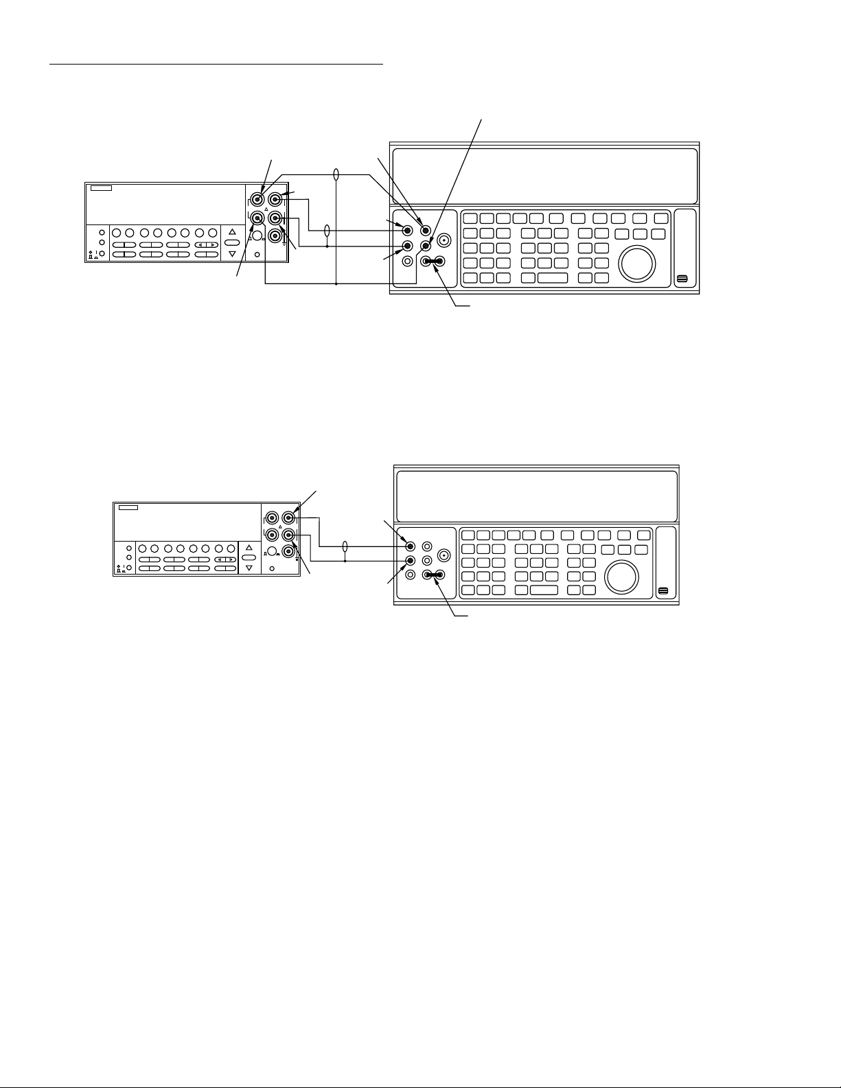
Calibration Programs
Sense HI
PREV
DCV ACV DCI ACI Ω2 Ω4
DISPLAY
NEXT
REL TRIG STORE RECALL
POWER
INFO LOCAL CHAN SCAN CONFIG MENU EXIT ENTER
Model 2001
2001 MULTIMETER
FREQ TEMP
FILTER MATH
SENSE
INPUT
Ω 4 WIRE
350V
PEAK
INPUTS
F
RANGE
FRONT/REAR
AUTO
RANGE
Input HI
HI
1100V
PEAK
LO
500V
PEAK
R
2A 250V
AMPS
CAL
Input
LO
Sense LO
Note : Use shielded cables to minimize noise.
Enable or disable calibrator external
sense as indicated in procedure. Use
internal Guard (EX GRD LED is off).
Figure B-2
Calibration connection for comprehensive calibration
Sense HI
Output HI
Output
LO
Sense LO
5700A Calibrator
Ground link installed.
Model 2001
PREV
DCV ACV DCI ACI Ω2 Ω4
DISPLAY
NEXT
REL TRIG STORE RECALL
POWER
INFO LOCAL CHAN SCAN CONFIG MENU EXIT ENTER
FREQ TEMP
FILTER MATH
Figure B-3
Calibration voltage connections
2001 MULTIMETER
RANGE
AUTO
RANGE
5700A Calibrator
Input HI
SENSE
INPUT
Ω 4 WIRE
HI
350V
1100V
PEAK
PEAK
LO
500V
PEAK
INPUTS
F
R
FRONT/REAR
2A 250V
AMPS
CAL
Input
LO
Output HI
Output
LO
Ground link installed.
Note: Use internal Guard (EX GRD LED is off).
B-4
Page 81

5700A Calibrator
Calibration Programs
Model 2001
PREV
DCV ACV DCI ACI Ω2 Ω4
DISPLAY
NEXT
REL TRIG STORE RECALL
POWER
INFO LOCAL CHAN SCAN CONFIG MENU EXIT ENTER
FILTER MATH
Figure B-4
Calibration current connections
Model 2001
PREV
DCV ACV DCI ACI Ω2 Ω4 FREQ TEMP
DISPLAY
NEXT
REL TRIG STORE RECALL
POWER
INFO LOCAL CHAN SCAN CONFIG MENU EXIT ENTER
FILTER MATH
2001 MULTIMETER
FREQ TEMP
2001 MULTIMETER
SENSE
Ω 4 WIRE
350V
PEAK
INPUTS
F
RANGE
FRONT/REAR
AUTO
RANGE
CAL
Input
INPUT
LO
HI
1100V
PEAK
LO
500V
PEAK
R
2A 250V
AMPS
Output HI
Amps
Output
LO
Ground link installed.
Note: Use internal Guard (EX GRD LED is off).
BNC-to-Dual
Banana Plug
Model 3930A Synthesizer
3930A MULTIFUNCTION SYNTHESIZER
Adapter
SENSE
INPUT
Ω 4 WIRE
HI
350V
1100V
PEAK
PEAK
LO
500V
INPUTS
PEAK
F
R
RANGE
FRONT/REAR
AUTO
RANGE
2A 250V
AMPS
CAL
Function
Output
Figure B-5
Synthesizer connections
50Ω BNC Coaxial Cable
B-5
Page 82

Calibration Programs
Program B-1
Comprehensive calibration program for use with any suitable calibrator (QuickBASIC Version).
B-6
Page 83

Program B-1 (continued)
Comprehensive calibration program for use with any suitable calibrator (QuickBASIC Version).
Calibration Programs
B-7
Page 84

Calibration Programs
Program B-2
Comprehensive calibration program for use with any suitable calibrator (Turbo C Version).
B-8
Page 85

Program B-2 (continued)
Comprehensive calibration program for use with any suitable calibrator (Turbo C Version).
Calibration Programs
B-9
Page 86

Calibration Programs
Program B-2 (continued)
Comprehensive calibration program for use with any suitable calibrator (Turbo C Version).
B-10
Page 87

Program B-3
Comprehensive calibration program for use with Fluke 5700A calibrator (QuickBASIC Version).
Calibration Programs
B-11
Page 88

Calibration Programs
Program B-3 (continued)
Comprehensive calibration program for use with Fluke 5700A calibrator (QuickBASIC Version).
B-12
Page 89

Program B-3 (continued)
Comprehensive calibration program for use with Fluke 5700A calibrator (QuickBASIC Version).
Calibration Programs
B-13
Page 90

Calibration Programs
Program B-4
Comprehensive calibration program for use with Fluke 5700A calibrator (Turbo C Version).
B-14
Page 91

Program B-4 (continued)
Comprehensive calibration program for use with Fluke 5700A calibrator (Turbo C Version).
Calibration Programs
B-15
Page 92

Calibration Programs
Program B-4 (continued)
Comprehensive calibration program for use with Fluke 5700A calibrator (Turbo C Version).
B-16
Page 93

Program B-5
Low-level calibration program for use with Fluke 5700A calibrator (QuickBASIC Version).
Calibration Programs
B-17
Page 94

Calibration Programs
Program B-5 (continued)
Low-level calibration program for use with Fluke 5700A calibrator (QuickBASIC Version).
B-18
Page 95

Program B-5 (continued)
Low-level calibration program for use with Fluke 5700A calibrator (QuickBASIC Version).
Calibration Programs
B-19
Page 96

Calibration Programs
Program B-5 (continued)
Low-level calibration program for use with Fluke 5700A calibrator (QuickBASIC Version).
B-20
Page 97

Program B-6
Low-level calibration program for use with Fluke 5700A calibrator (Turbo C Version).
Calibration Programs
B-21
Page 98

Calibration Programs
Program B-6 (continued)
Low-level calibration program for use with Fluke 5700A calibrator (Turbo C Version).
B-22
Page 99

Program B-6 (continued)
Low-level calibration program for use with Fluke 5700A calibrator (Turbo C Version).
Calibration Programs
B-23
Page 100

Calibration Programs
Program B-6 (continued)
Low-level calibration program for use with Fluke 5700A calibrator (Turbo C Version).
B-24
 Loading...