

Keithley System SourceMeter 2601B, System SourceMeter 2602B, System SourceMeter 2604B Instrument Specifications
Page 1
Models 2601B, 2602B and 2604B
SPEC-2602B Rev. B / February 2014 1 of 13
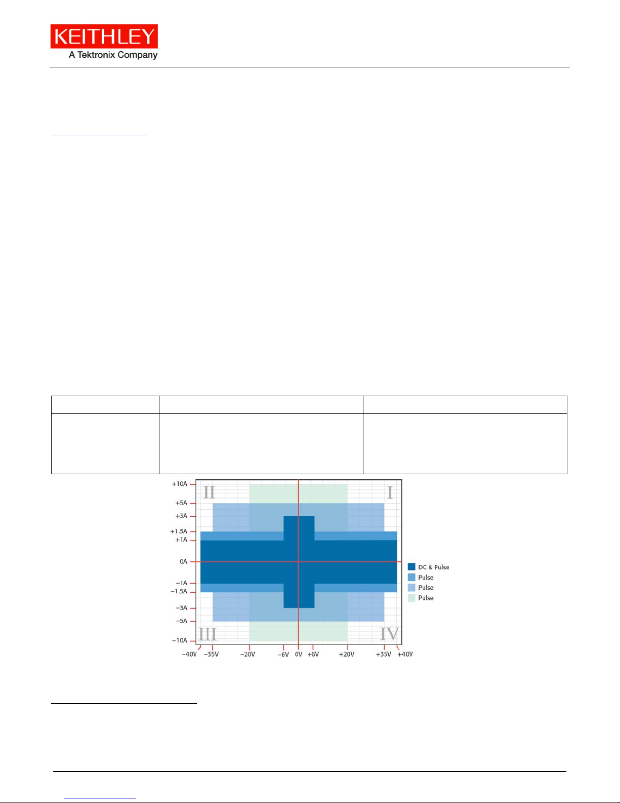
Four-quadrant source or sink operation
Four-quadrant source or sink operation
Keithley Instruments, Inc. System SourceMeter
28775 Aurora Road
Cleveland, Ohio 44139
1-888-KEITHLEY
http://www.keithley.com
Instrument Specifications
®
SPECIFICATION CONDITIONS
This document contains specifications and supp lemental in formation for t he Mod els 2601B, 2602B and
2604B System SourceMeter
®
instrument. Spec ificati ons are the st andar ds against whic h the Models
2601B, 2602B and 2604B are tested. Upon leaving the factory, the Models 2601B, 2602B and 2604B meet
these sp ecifications. Supp l em ental and typ ical valu es are nonw ar ran ted, appl y at 23 °C, and are provid ed
solely as us eful information.
Source and measu r emen t accur acies are speci fied at the Models 2601B, 2602B and 2604B terminals
under these conditions:
1. 23 °C ± 5 ° C , < 70 perc ent relativ e hum idity
2. After a two-hour w ar m-up period
3. Spee d no r ma l (1 NP LC)
4. A/D autozero enabled
5. Remote sense operation or properly zer oed local operation
6. Cal i bration period: One year
DC POWER SPECIFICATIONS
Voltage Current
Maximum output
power and
source/sink limits1
40.4 W maxi mum
± (40.4 V at 1.0 A, -1.0 A)
± (6.06 V at 3.0 A, -3.0 A)
40.4 W maxi mum
± (1.01 A at 40 V, -40 V)
± (3.03 A at 6 V, -6 V)
Refer to the “Pulse Characteristics” section for pulsing details, such as duty cycle and pulse width.
1
Full power source operation regardless of loa d to 30 °C ambient temperature. Abov e 30 °C or power sink operation, refer to “Operat ing
Boundaries” in the Series 2600B Reference Manual for additional power derating information.
Specifications are subject to change without notice
Page 2
Models 2601B, 2602B and 2604B System SourceMeter® Instrument Specifications
2 of 13 SPEC-2602B Rev. B / February 2014
VOLTAGE ACCURACY SPECIFICATIONS
2,3
Source Measure
Range
Programming
resolution
Accuracy
± (% reading + volts)
Typical Noise
(Peak to Peak)
0.1 Hz to 10 Hz
Display
resolution
Accuracy4
± (% reading + volts)
100 mV 5 µV 0.02 % + 250 µV 20 µV 100 nV 0.015 % + 150 µV
1 V 50 µV 0.02 % + 400 µV 50 µV 1 µV 0.015 % + 200 µV
6 V 50 µV 0.02 % + 1.8 mV 100 µV 1 µV 0.015 % + 1 mV
40 V 500 µV 0.02 % + 12 mV 500 µV 10 µV 0.015 % + 8 mV
CURRENT ACCURACY SPECIFICATIONS2
Source Measure
Programming
resolution
Range
100 nA 2 pA 0.06 % + 100 pA 5 pA 100 fA 0.05 % + 100 pA
1 µA 20 pA 0.03 % + 800 pA 25 pA 1 pA 0.025 % + 500 pA
10 µA 200 pA 0.03 % + 5 nA 60 pA 10 pA 0.025 % + 1.5 nA
100 µA 2 nA 0.03 % + 60 nA 3 nA 100 pA 0.02 % + 25 nA
Accuracy
± (% reading + amperes)
Typical Noise
(Peak to Peak)
0.1 Hz to 10 Hz
Display
resolution
Accuracy4
± (% reading + amperes)
1 mA 20 nA 0.03 % + 300 nA 6 nA 1 nA 0.02 % + 200 nA
10 mA 200 nA 0.03 % + 6 µA 200 nA 10 nA 0.02 % + 2.5 µA
100 mA 2 µA 0.03 % + 30 µA 600 nA 100 nA 0.02 % + 20 µA
1 A 20 µA 0.05 % + 1.8 mA 70 µA 1 µA 0.03 % + 1.5 mA
3 A 20 µA 0.06 % + 4 mA 150 µA 1 µA 0.05 % + 3.5 mA
10 A5 200 µA 0.5 % + 40 mA N/A 10 µA 0.4 % + 25 mA
2
For temperatures 0 °C to 18 °C and 28 °C to 50 °C, accuracy is degraded by ± (0.15 × accuracy specification)/°C. High Capacitance Mode
accuracy is applic ab le at 23 °C ± 5 °C.
3
Add 50 µV to source accuracy specifications per volt of HI lead drop.
4
Derate accuracy specification for NPLC setting < 1 by increasing the error term. Add appropriate typical percent of r eading term for resistive
loads usi ng the table below.
NPLC setting 100 mV range 1 V and 40 V ranges 100 nA range 1 µA to 100 m A ranges 1 A to 3 A ranges
0.1 0.01 % 0.01 % 0.01 % 0.01 % 0.01 %
0.01 0.08 % 0.07 % 0.1 % 0.05 % 0.05 %
0.001 0.8 % 0.6 % 1 % 0.5 % 1.1 %
5
10 A range is accessible in pulse mode only. A cc uracy specificatio ns for 10 A range are typical.
Specifications are subject to change without notice
Page 3
Models 2601B, 2602B and 2604B System SourceMeter Instrument Specifications
SPEC-2602B Rev. B / February 2014 3 of 13
SUPPLEMENTAL CHARAC TERISTICS
The followin g specific ation s are supplem ental charact er isti cs t hat provide additional i nform ation about
ins trum ent functi ons and perform ance. These characteristics are nonwarranted specifications; they
describe the typical performance of th e Models 2601B, 2602B and 2604B.
PULSE CHARACTERISTI CS
Pulse region specifications Pulse region specifications
Region
quadrant diagram
Region
maximums
1 1 A at 40 V DC, no limit 100 %
1 3 A at 6 V DC, no limit 100 %
2 1.5 A at 40 V 100 ms 25 %
3 5 A at 35 V 4 ms 4 %
4 10 A at 20 V 1.8 ms 1 %
6
Times measured from the start of pulse to the start off-time; see figure below.
Maximum pulse
width6
Maximum duty
cycle7
7
Thermally limited in sink mode (quadrants 2 and 4) and ambient temperatures above 30° C. See power equations in the S e ries 260 0B
Reference Manual for more information.
Specifications are subject to change without notice
Page 4
Models 2601B, 2602B and 2604B System SourceMeter® Instrument Specifications
4 of 13 SPEC-2602B Rev. B / February 2014
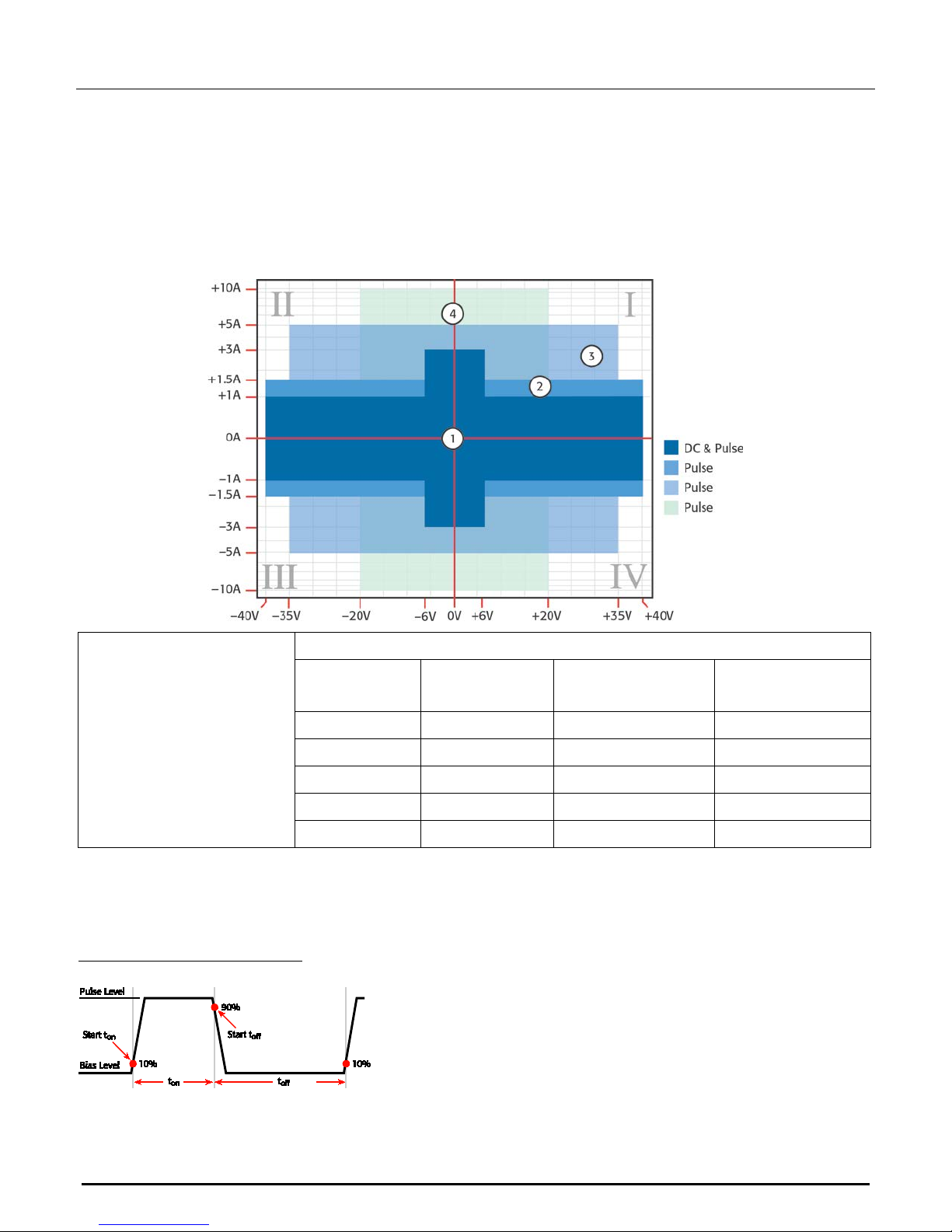
Minimum programmable
100 µs
be longer than 100 ms.
Source value
Load
Source settling time
(% of range)
Minimum pulse
width
6 V
2 Ω
0.2 %
150 µs
20 V
2 Ω
1 %
200 µs
35 V
7 Ω
0.5 %
500 µs
40 V
27 Ω
0.1 %
400 µs
1.5 A
27 Ω
0.1 %
1.5 ms
3 A
2 Ω
0.2 %
150 µs
5 A
7 Ω
0.5 %
500 µs
10 A
2 Ω
0.5 %
200 µs
6 V range
See Current source output settling time for additional test conditions
< 300 mV/R
load
+ 5 % of larger range
Current < 10 mA
pulse width6
Pulse width programming
resolution
Pulse width programming
accuracy
Pulse width jitter
Note: Minimum pulse width for settled source at a given I/V output and load can
1 µs
± 5 µs
2 µs
ADDITIONAL SOURCE CHARACTERISTICS
Noise
10 Hz to 20 MHz
Transient response time
< 20 mV peak-peak, < 3 mV RMS
< 70 µs for the output to recover to within 0.1 % for a 10 % to 90 % step change in load.
Overshoot
Range change overshoot
Guard offset voltage
Remote sense operating
range9
Voltage:
< ±0.1 % + 10 mV
Step size = 10 % to 90 % of range, resistive load, maximum current
limit/compliance
Current:
< ±0.1 %
Step size = 10 % to 90 % of range, resistive load
Voltage:
< 300 mV + 0.1 % of larger range
Overshoot into a 100 kΩ load, 20 MHz bandwidth
Current:8
< 4 mV
Maximum voltage between HI and SENSE HI = 3 V
Maximum voltage between LO and SENSE LO = 3 V
8
With source settling set to SETTLE_SMOOTH_100NA
9
Add 50 µV to source accuracy specifications per volt of HI lead drop.
Specifications are subject to change without notice
Page 5

Models 2601B, 2602B and 2604B System SourceMeter Instrument Specifications
SPEC-2602B Rev. B / February 2014 5 of 13
Minimum value is 10 nA; accuracy is the same as current source
Voltage output headr oom 40 V range
Maximum output voltage = 42 V – (total voltage drop across source leads).
Maximum 1 Ω source lead.
6 V range
Maximum output voltage = 8 V – (total voltage drop across source leads).
Maximum 1 Ω source lead.
Over-temperature protection
Internally sensed temperature overload puts the instrument in standby mode
Limit/compliance
Voltage source output
settling time
Current source output
settling time
Bipolar limit (compliance) set with a single value
Voltage:10
Minimum value is 10 mV; accuracy is the same as voltage source
Current:
11
Time required to reach within 0.1 % of final value after source level command is
processed on a fixed range.
Voltage range Settlin g time
100 mV < 50 µs
1 V < 50 µs
10 V < 110 µs
40 V12 < 150 µs
Time required to reach within 0.1 % of final value after source level command is
processed on a fixed range
Values below for I
Current range Settlin g time
3 A < 80 µs (Current < 2.5 A, R
1 A to 10 mA < 80 µs (R
1 mA < 100 µs
out
× R
load
= 1 V
> 6 Ω)
load
> 2 Ω)
load
100 µA < 150 µs
10 µA < 500 µs
1 µA < 2 ms
100 nA < 20 ms
10
For sink operation (quadrants II and IV) wit ho ut si nk mode enab l ed, add 10 % of compliance range and ±0.02 % of limit settling to the
corresponding voltage source accuracy specifications. For 100 mV range add an additional 60 mV of uncertainty. Specifications apply with
sink mode enabled.
11
For sink operation (quadrants II and IV) without sink mode enabled, add 0.06 % of limit range to the corresponding current limit accuracy
specifications. Specifications apply with sink mode enabled.
12
Add 150 µs when measuring on the 1 A range.
Specifications are subject to change without notice
Page 6

Models 2601B, 2602B and 2604B System SourceMeter® Instrument Specifications
6 of 13 SPEC-2602B Rev. B / February 2014
Current measure settling
Time required to reach within 0.1 % of final value after source level command is
ADDITIONAL ME ASUREMENT CHARACTERISTICS
Contact check
specifications
13,14
Speed
Fast 1.1 ms (1.2 ms) 5 % + 10 Ω
Medium 4.1 ms (5 ms) 5 % + 1 Ω
Slow 36 ms (42 ms) 5 % + 0.3 Ω
time15
processed on a fixed range
Values below for Vout = 1 V
Current range Settling time
1 mA < 100 µs
Input impedance
> 10 GΩ
ADDITIONAL CHARACTERISTICS
Maximum load impedanc e Normal mode
10 nF
Common mode voltage
Common mode isolation
250 V DC
> 1 GΩ
< 4500 pF
Maximum measurement time
to memory for 60 Hz (50 Hz)
High-capacitance mode
50 µF
Accuracy (1 year)
23° C ± 5° C
± ( % reading + ohms)
Sense high input impedance
Maximum sense lead
resistance
Overrange
13
Includes measurement of SENSE HI to HI and SENSE LO to LO contact resistances.
14
Contact check is not available with the Model 2604B.
15
Com pliance equal to 100 mA
> 10 GΩ
1 kΩ for rated accuracy
101 % of source range
102 % of measure range
Specifications are subject to change without notice
Page 7

Models 2601B, 2602B and 2604B System SourceMeter Instrument Specifications
SPEC-2602B Rev. B / February 2014 7 of 13
Current measure settling time
Time required to reach within 0.1 % of final value after source level command is
11 ms delay out of High Capacitance Mode
6 V range
Overshoot into a 100 kΩ load, 20 MHz bandwidth
HIGH CAPACITANCE MODE
16,17,18
Accuracy specifications
Voltage source output
settling time
Accuracy specifications are applicable in both Normal and High Capacitance Modes.
Time required to reach within 0.1 % of final value after source level command is
processed on a fixed range.
Current limit = 1 A
Voltage range Settlin g time with C
= 4.7 µF
load
100 mV < 200 µs
1 V < 200 µs
6 V < 200 µs
40 V < 7 ms
processed on a fixed range
Values below for Vout = 1 V unless noted
Current range Settlin g time
3 A and 1A < 120 µs (R
> 2 Ω)
load
100 mA and 10 mA < 100 µs
1 mA < 3 ms
100 µA < 3 ms
10 µA < 230 ms
Capacitor leakage
performance
Using HIGH-C scripts19
Mode change delay
Voltmeter input im pedance
Noise
10 Hz to 20 MHz
Range change overshoot
16
High Capacitance Mode specifications are for DC measurements only.
17
100 nA range is not available in High Capacitance Mode.
18
High Capacitance Mode utilizes locked ranges. Auto range is disabled.
19
Part of KI Factory scripts. See the Series 2600B Reference Manual for details.
1 µA < 230 ms
200 ms @ 50 nA
Load = 5 µF in parallel with 10 MΩ
Test: 5 V step and measure
Current ranges of 100 µA and above:
11 ms delay for both in and out of High Capacitance Mode
Current ranges below 100 µA:
250 ms delay into High Capacitance Mode
10 GΩ in parallel with 3300 pF
< 30 mV peak-peak
Voltage:
< 400 mV + 0.1 % of larger range
Specifications are subject to change without notice
Page 8

Models 2601B, 2602B and 2604B System SourceMeter® Instrument Specifications
8 of 13 SPEC-2602B Rev. B / February 2014
MEASUREMENT SPEED CHARACTERISTICS
20,21
Maximum sweep operation rates (operations per second) for 60 H z (50 Hz):
A/D
converter
Trigger
origin
speed
0.001 NPLC Internal
0.001 NPLC Digital I/O
0.01 NPLC Internal
0.01 NPLC Digital I/O
0.1 NPLC Internal
0.1 NPLC Digital I/O
1.0 NPLC Internal
1.0 NPLC Digital I/O
Measure to
memory
(using user
scripts)
20000
(20000)
8100
(8100)
4900
(4000)
3500
(3100)
580
(480)
550
(460)
59
(49)
59
(49)
Measure to
GPIB
(using user
scripts)
9800
(9800)
7100
(7100)
3900
(3400)
3400
(3000)
560
(470)
550
(460)
59
(49)
59
(49)
Source
measure to
memory
(using user
scripts)
7000
(7000)
5500
(5500)
3400
(3000)
3000
(2700)
550
(465)
540
(450)
59
(49)
59
(49)
Source
measure to
GPIB
(using user
scripts)
6200
(6200)
5100
(5100)
3200
(2900)
2900
(2600)
550
(460)
540
(450)
59
(49)
59
(49)
Source
measure to
memory
(using sweep
API)
12000
(12000)
11200
(11200)
4200
(3700)
4150
(3650)
560
(470)
560
(470)
59
(49)
59
(49)
Source
measure to
GPIB
(using sweep
API)
5900
(5900)
5700
(5700)
4000
(3500)
3800
(3400)
545
(460)
545
(460)
59
(49)
59
(49)
Maximum sing l e m e as u rement r ates (operations per second) for 60 Hz (50 Hz):
A/D converter speed Trigger or igin Measure to GPIB
Source measure to
GPIB
0.001 NPLC Internal 1900 (1800) 1400 (1400) 1400 (1400)
0.01 NPLC Internal 1450 (1400) 1200 (1200) 1100 (1100)
0.1 NPLC Internal 450 (390) 425 (370) 425 (375)
1.0 NPLC Internal 58 (48) 57 (48) 57 (48)
20
Tests performed with a Model 2602B using the following equipment: Computer hardware (Intel
Instruments™ PCI-GPIB); driv er (NI -488.2 Version 2.2 PCI-GPIB); software (Microsoft
version 4.1).
21
Exclude current measurement ranges less than 1 mA.
®
®
Pentium® 4 2.4 GHz, 2 GB RAM, National
Windows® XP, Microsof t® Visual Studio® 2010, VISA™
Source measure
pass/fail to GPIB
Specifications are subject to change without notice
Page 9

Models 2601B, 2602B and 2604B System SourceMeter Instrument Specifications
SPEC-2602B Rev. B / February 2014 9 of 13
smua.source.levelv
smua.source.leveli
Maximum measurement
range change rate
Maximum source range
change rate
Maximum source function
> 7000 per second for > 10 µA. When changing to or from a range ≥ 1 A, maximum rate
is > 2200/second.
> 400 per second > 10 µA. When changing to or from a range ≥ 1 A, maximum rate is >
190/second.
> 1000 per second
change rate
Command processing time
< 1 ms
Maximum time required for the output to begin to change after receiving the
or
TRIGGERING AND SYNCHRONIZATION CHARACTERISTICS
Triggering
Trigger in to trigger out
Trigger in to source
change22
Trigger timer accuracy
0.5 μs
10 μs
±2 μs
command.
Source change22 after LXI
trigger
Synchronization
Multi-node synchronized
source change22
Single-node synchronized
source change22
280 μs
< 0.5 μs
< 0.5 μs
22
Fixed source range with no polarity change.
Specifications are subject to change without notice
Page 10

Models 2601B, 2602B and 2604B System SourceMeter® Instrument Specifications
10 of 13 SPEC-2602B Rev. B / February 2014
View measurements stored in dedicated reading buffers
Able to execute high-speed test scripts stored in memory without host intervention
Microsoft
Windows® 2000, XP, Vista®, or 7
browser
SUPPLEMENTAL INFORMATION
Front-panel interface
Display
Two-line vacuum fluorescent display (VFD) with keypad and navigation wheel
Show error messages and user-defined messages
Display source and limit settings
Show current and voltage measurements
Keypad operati ons
Change host interface settings
Save and restore instrument setups
Load and run factory and user-defined test scripts that prompt for input and send
results to the display
Store measurements into dedicated reading buffers
Programming Embedded Test Script Processor (TSP®) scripting engine is accessible from any host
interface:
Responds to individual instrument control commands
Responds to high-speed test scripts comprised of remote commands and test script
language (TSL) statements (for example, branching, looping, and math)
Minimum user memory
available
Test Script Builder Integrated development environment for building, running, and managing TSP scripts;
16 MB (approximately 250,000 lines of TSP code)
includes an instrument console for interactive communication with any TSP-enabled
instrument
Requires:
VISA (NI-VISA included on the Product Information CD-ROM)
Microsoft
®
.NET Framework (included on the Product Information CD-ROM)
Keithley I/O Layer (included on the Product Information CD-ROM)
Intel
TSP® Express (embedded) Tool that allows you to quickly and easily perform common I-V tests without programming
or installing software
To run TSP Express, you need:
®
Pentium III 800 MHz or faster personal computer
®
Java™ Platform, Standard Edition 6 or 7
Microsoft
Software interface TSP™ Express (embedded), direct GPIB/VISA, read/write with Microsoft® Visual Basic®,
Visual C/C++®, Visua l C#®, LabVIEW™, CEC TestPoint™ Data Acquisition Software
Package, NI LabWindows™/CVI, and so on.
®
Internet Explorer®, Mozilla® Firefox®, or another Java-compatible web
Specifications are subject to change without notice
Page 11

Models 2601B, 2602B and 2604B System SourceMeter Instrument Specifications
SPEC-2602B Rev. B / February 2014 11 of 13
instrument uses one TSP-Link node
Free-running 47-bit counter with 1 MHz clock input. Reset each time instrument power is
Reading buffers Nonvolatile memory uses dedicated storage areas reserved for measurement data.
Reading buffers are arrays of measurement elements. Each element can store the
following items:
Measurement
Source setting (at the time the measurement was taken)
Measurement status
Range information
Timestamp
Reading buffers can be filled using the front-panel STORE key, and retrieved using the
RECALL key or host interface.
Buffer si ze, with timestamp
and source setting
Buffer size, without
timestamp and source
setting
System expansion23 The TSP-Link expansion interface allows TSP-enabled instruments to trigger and
> 60,000 samples
> 140,000 samples
communicate with each other. See the figure below.
Each Model 2601B and 2602B has two TSP-Link connectors to make it easier to connect
instruments in a sequence.
Once source-measure instruments are interconnected through the TSP-Link
expansion interface, a computer can access all of the resources of each
source-measure instrument through the host interface of any System SourceMeter.
A maximum of 32 TSP-Link nodes can be interconnected. Each source-measure
Timing
Timer
Timestamp
Resolution
Timestamp accuracy
23
TSP-Link is not available with the Model 2604B.
Specifications are subject to change without notice
turned on. If the instrument is not turned off, the timer is automatically reset to zero (0)
every four years.
TIMER value is automatically saved when each measurement is triggered
1 μs
±100 ppm
Page 12

Models 2601B, 2602B and 2604B System SourceMeter® Instrument Specifications
12 of 13 SPEC-2602B Rev. B / February 2014
2604B can use the RS-232 interface to control other instruments
9.84 ft (3 m) maximum between each TSP-enabled instrument
GENERAL SPECIFICATIONS
IEEE-488 IEEE Std 488.1 compliant. Supports IEEE Std 488.2 common commands and status
model topology
RS-232
Baud rates from 300 bps to 115,200 bps
Programmable number of data bits, parity type, and flow control (RTS/CTS hardware
or none)
When not programmed as the active host interface, the Models 2601B, 2602B and
Ethernet
LXI compliance
Expansion interface24
RJ-45 connector, LXI version 1.4 Core 2011, 10/100BaseT, Auto-MDIX
LXI version 1.4 Core 2011
The TSP-Link® expansion interface allows TSP-enabled instruments to trigger and
communicate with each other
Cable type: Category 5e or higher LAN crossover cable
USB Control (Rear)
USB File System (Front)
Power supply
Cooling Forced air; side intake and rear exhaust. One side must be unobstructed when rack
USB 2.0 Device: USB-TMC488 protocol
USB 2.0 Host: Mass storage class device
100 V to 240 V AC, 50 Hz or 60 Hz (auto sensing), 240 VA maximum
mounted.
Warranty
EMC
Safety
Environment
Dimensions
Weight 2601B: 10.4 lb (4.75 kg)
24
TSP-Link is not available with the Model 2604B.
1 year
Conforms to European Union EMC Directive
NRTL listed to UL61010-1:2008 and CSA C22.2 No. 61010-1
Conforms to European Union Low Voltage Directive
For indoor use only
Altitude: Maximum 6562 ft (2000 m) above sea level
Operating: 0 °C to 50 °C, 70 % relative humidity up to 35 °C. Derate 3 % relative
humidity/°C, 35 °C to 50 °C
Storage: -25 °C to 65 °C
Rack mount: 3.5 in. high × 8.4 in. wide × 17.5 in. deep (89 mm × 213 mm × 460 mm)
Bench configuration (with handle and feet): 4.1 in. high × 9.4 in. wide × 17.5 in. deep
(104 mm × 238 mm × 460 mm)
2602B and 2604B: 12.0 lb (5.50 kg)
Specifications are subject to change without notice
Page 13

Models 2601B, 2602B and 2604B System SourceMeter Instrument Specifications
SPEC-2602B Rev. B / February 2014 13 of 13
current = 2.1 V / 10 kΩ = 210 µA).
Digital I/O interface25
Connector: 25-pin female D
Input/output pins: 14 open drain I/O bits
Absolute maximum i nput voltage: 5.25 V
Absolute minimum input voltage: -0.25 V
Maximum logic low input voltage: 0.7V, +850 µA max
Minimum logic high input voltage: 2.1 V, +570 µA
Maximum source current (flowing out of digital I/O bit): +960 µA
Maximum sink current at maximum logic low voltage (0.7 ): -5.0 mA
Absolute maximum sink current (flowing into digital I/O pin: -11 mA
5 V power s upply pins: Limited to 250 mA total, solid-state fuse protected
Output Enable: Active high input pulled down internally to ground with a 10 kΩ resistor;
when the output enable input function has been activated, each SourceMeter
channel will not turn on unless the output enable pin is driven to > 2.1 V (nominal
25
The Digital I/O feature is not available with the Model 2604B. Only +5 V, GND and INTERLOCK pins are available with the Model 2604B
Specifications are subject to change without notice
 Loading...