

Keithley SourceMeter 2611, SourceMeter 2602, SourceMeter 2612, SourceMeter 2601 User Manual
Page 1

www.keithley.com
Series 2600 System SourceMeter
®
User’s Manual
2600S-900-01 Rev. A / May 2006
A GREATER MEASURE OF CONFIDENCE
Page 2

WARRANTY
Keithley Instruments, Inc. warrants this product to be free from defects in material and workmanship for a
period of 1 year from date of shipment.
Keithley Instruments, Inc. warrants the following items for 90 days from the date of shipment: probes, cables,
rechargeable batteries, diskettes, and documentation.
During the warranty period, we will, at our option, either repair or replace any product that proves to be defective.
To exercise this warranty, write or call your local Keithley representative, or contact Keithley headquarters in
Cleveland, Ohio. You will be given prompt assistance and return instructions. Send the product, transportation
prepaid, to the indicated service facility. Repairs will be made and the product returned, transportation prepaid.
Repaired or replaced products are warranted for the balance of the original warranty period, or at least 90 days.
LIMITATION OF WARRANTY
This warranty does not apply to defects resulting from product modification without Keithley’s express written
consent, or misuse of any product or part. This warranty also does not apply to fuses, software, non-recharge
able batteries, damage from battery leakage, or problems arising from normal wear or failure to follow instructions.
THIS WARRANTY IS IN LIEU OF ALL OTHER WARRANTIES, EXPRESSED OR IMPLIED, INCLUDING ANY IMPLIED WARRANTY OF MERCHANTABILITY OR FITNESS FOR A PARTICULAR USE.
THE REMEDIES PROVIDED HEREIN ARE BUYER’S SOLE AND EXCLUSIVE REMEDIES.
NEITHER KEITHLEY INSTRUMENTS, INC. NOR ANY OF ITS EMPLOYEES SHALL BE LIABLE
FOR ANY DIRECT, INDIRECT, SPECIAL, INCIDENTAL OR CONSEQUENTIAL DAMAGES ARISING
OUT OF THE USE OF ITS INSTRUMENTS AND SOFTWARE EVEN IF KEITHLEY INSTRUMENTS,
INC., HAS BEEN ADVISED IN ADVANCE OF THE POSSIBILITY OF SUCH DAMAGES. SUCH
EXCLUDED DAMAGES SHALL INCLUDE, BUT ARE NOT LIMITED TO: COSTS OF REMOVAL
AND INSTALLATION, LOSSES SUSTAINED AS THE RESULT OF INJURY TO ANY PERSON, OR
DAMAGE TO PROPERTY.
-
A G R E A T E R M E A S U R E O F C O N F I D E N C E
Keithley Instruments, Inc.
Corporate Headquarters • 28775 Aurora Road • Cleveland, Ohio 44139
440-248-0400 • Fax: 440-248-6168 • 1-888-KEITHLEY (534-8453) • www.keithley.com
12/04
Page 3

Series 2600 System
®
SourceMeter
Instruments
User’s Manual
©2006, Keithley Instruments, Inc.
All rights reserved.
Cleveland, Ohio, U.S.A.
Document Number: 2600S-900-01 Rev. A
Page 4

Manual Print History
The print history shown below lists the printing dates of all Revisions and Addenda created for this manual. The Revision Level letter increases alphabetically as the manual undergoes subsequent updates. Addenda, which are released between Revisions, contain
important change information that the user should incorporate immediately into the manual.
Addenda are numbered sequentially. When a new Revision is created, all Addenda associ
ated with the previous Revision of the manual are incorporated into the new Revision of the
manual. Each new Revision includes a revised copy of this print history page.
Revision A (Document Number 2600S-900-01).................................................................. May 2006
-
All Keithley product names are trademarks or registered trademarks of Keithley Instruments, Inc.
Other brand names are trademarks or registered trademarks of their respective holders.
Page 5

Safety Precautions
The following safety precautions should be observed before using this product and any associated instrumentation. Although
some instruments and accessories would normally be used with non-hazardous voltages, there are situations where hazardous
conditions may be present.
This product is intended for use by qualified personnel who recognize shock hazards and are familiar with the safety precautions
required to avoid possible injury. Read and follow all installation, operation, and maintenance information carefully before using the product. Refer to the manual for complete product specifications.
If the product is used in a manner not specified, the protection provided by the product may be impaired.
The types of product users are:
Responsible body is the individual or group responsible for the use and maintenance of equipment, for ensuring that the
equipment is operated within its specifications and operating limits, and for ensuring that operators are adequately trained.
Operators use the product for its intended function. They must be trained in electrical safety procedures and proper use of the
instrument. They must be protected from electric shock and contact with hazardous live circuits.
Maintenance personnel perform routine procedures on the product to keep it operating properly, for example, setting the line
voltage or replacing consumable materials. Maintenance procedures are described in the manual. The procedures explicitly state
if the operator may perform them. Otherwise, they should be performed only by service personnel.
Service personnel are trained to work on live circuits, and perform safe installations and repairs of products. Only properly
trained service personnel may perform installation and service procedures.
Keithley products are designed for use with electrical signals that are rated Measurement Category I and Measurement Category
II, as described in the International Electrotechnical Commission (IEC) Standard IEC 60664. Most measurement, control, and
data I/O signals are Measurement Category I and must not be directly connected to mains voltage or to voltage sources with
high transient over-voltages. Measurement Category II connections require protection for high transient over-voltages often
associated with local AC mains connections. Assume all measurement, control, and data I/O connections are for connection to
Category I sources unless otherwise marked or described in the Manual.
Exercise extreme caution when a shock hazard is present. Lethal voltage may be present on cable connector jacks or test fixtures.
The American National Standards Institute (ANSI) states that a shock hazard exists when voltage levels greater than 30V RMS,
42.4V peak, or 60VDC are present. A good safety practice is to expect that hazardous voltage is present in any unknown
circuit before measuring.
Operators of this product must be protected from electric shock at all times. The responsible body must ensure that operators
are prevented access and/or insulated from every connection point. In some cases, connections must be exposed to potential
human contact. Product operators in these circumstances must be trained to protect themselves from the risk of electric shock.
If the circuit is capable of operating at or above 1000 volts, no conductive part of the circuit may be exposed.
Do not connect switching cards directly to unlimited power circuits. They are intended to be used with impedance limited
sources. NEVER connect switching cards directly to AC mains. When connecting sources to switching cards, install protective
devices to limit fault current and voltage to the card.
Before operating an instrument, make sure the line cord is connected to a properly grounded power receptacle. Inspect the
connecting cables, test leads, and jumpers for possible wear, cracks, or breaks before each use.
When installing equipment where access to the main power cord is restricted, such as rack mounting, a separate main input
power disconnect device must be provided, in close proximity to the equipment and within easy reach of the operator.
5/03
Page 6

For maximum safety, do not touch the product, test cables, or any other instruments while power is applied to the circuit under
test. ALWAYS remove power from the entire test system and discharge any capacitors before: connecting or disconnecting
cables or jumpers, installing or removing switching cards, or making internal changes, such as installing or removing jumpers.
Do not touch any object that could provide a current path to the common side of the circuit under test or power line (earth) ground.
Always make measurements with dry hands while standing on a dry, insulated surface capable of withstanding the voltage being
measured.
The instrument and accessories must be used in accordance with its specifications and operating instructions or the safety of the
equipment may be impaired.
Do not exceed the maximum signal levels of the instruments and accessories, as defined in the specifications and operating
information, and as shown on the instrument or test fixture panels, or switching card.
When fuses are used in a product, replace with same type and rating for continued protection against fire hazard.
Chassis connections must only be used as shield connections for measuring circuits, NOT as safety earth ground connections.
If you are using a test fixture, keep the lid closed while power is applied to the device under test. Safe operation requires the use
of a lid interlock.
If a screw is present, connect it to safety earth ground using the wire recommended in the user documentation.
The ! symbol on an instrument indicates that the user should refer to the operating instructions located in the manual.
The symbol on an instrument shows that it can source or measure 1000 volts or more, including the combined effect of
normal and common mode voltages. Use standard safety precautions to avoid personal contact with these voltages.
The symbol indicates a connection terminal to the equipment frame.
The WARNING heading in a manual explains dangers that might result in personal injury or death. Always read the associated
information very carefully before performing the indicated procedure.
The CAUTION heading in a manual explains hazards that could damage the instrument. Such damage may invalidate the
warranty.
Instrumentation and accessories shall not be connected to humans.
Before performing any maintenance, disconnect the line cord and all test cables.
To maintain protection from electric shock and fire, replacement components in mains circuits, including the power transformer,
test leads, and input jacks, must be purchased from Keithley Instruments. Standard fuses, with applicable national safety
approvals, may be used if the rating and type are the same. Other components that are not safety related may be purchased from
other suppliers as long as they are equivalent to the original component. (Note that selected parts should be purchased only
through Keithley Instruments to maintain accuracy and functionality of the product.) If you are unsure about the applicability
of a replacement component, call a Keithley Instruments office for information.
To clean an instrument, use a damp cloth or mild, water based cleaner. Clean the exterior of the instrument only. Do not apply
cleaner directly to the instrument or allow liquids to enter or spill on the instrument. Products that consist of a circuit board with
no case or chassis (e.g., data acquisition board for installation into a computer) should never require cleaning if handled
according to instructions. If the board becomes contaminated and operation is affected, the board should be returned to the
factory for proper cleaning/servicing.
Page 7

Table of Contents
Section Title Page
1 Front Panel Operation
Safety symbols and terms .......................................................................... 1-2
Front and rear panel familiarization ............................................................ 1-2
Front panel summaries ........................................................................ 1-2
Rear panel summaries ......................................................................... 1-6
What are the source-measure capabilities? ............................................... 1-8
Models 2601 and 2602 ........................................................................ 1-8
Models 2611 and 2612 ........................................................................ 1-8
How do I power-up the instrument? ........................................................... 1-9
How do I make measurements? .............................................................. 1-10
How do I use the buffer? .......................................................................... 1-15
2 Remote Operation
How do I use the remote interface? ........................................................... 2-2
How do I use Test Script Builder? .............................................................. 2-4
How do I use TSB to make measurements? .............................................. 2-9
How do I use other programs? ................................................................. 2-12
Using LabVIEW ................................................................................. 2-12
Using Visual Basic ............................................................................. 2-14
3 Test Script Processor Interaction
What is a script? ......................................................................................... 3-2
Factory scripts ..................................................................................... 3-2
User scripts .......................................................................................... 3-2
How do I run a script from the front panel? ................................................ 3-2
How do I interact with scripts using Test Script Builder? ............................ 3-3
Running a factory script ....................................................................... 3-4
Modifying a factory script ..................................................................... 3-6
2600S-900-01 Rev. A / May 2006 i
Page 8

Table of Contents Series 2600 System SourceMeters User’s Manual
Running the user script ...................................................................... 3-12
Deleting a user script and user tests ................................................ 3-13
How do I use other programs? ................................................................. 3-14
Using LabVIEW ................................................................................. 3-14
Using Visual Basic ............................................................................. 3-16
4 Controlling Multiple SourceMeters (TSP-Link)
How do I set up the TSP-Link system? ...................................................... 4-2
How do I use the expanded system? ......................................................... 4-4
Accessing resources of TSP-Link nodes ............................................. 4-4
Running scripts in a TSP-Link system ................................................. 4-5
Appendix Title Page
A Specifications
.................................................................................................................. A-2
B Frequently Asked Questions
How do I optimize performance? .............................................................. B-2
Setting speed ...................................................................................... B-2
Disabling auto zero to increase speed ............................................... B-2
How do I use the Digital I/O port? ............................................................. B-3
Digital I/O port terminals ..................................................................... B-3
Controlling the Digital I/O port ............................................................. B-3
How do I trigger other instruments? .......................................................... B-5
Triggering a scanner ........................................................................... B-5
Programming triggering ...................................................................... B-5
How do I generate a service request? ...................................................... B-6
Setting up a service request ............................................................... B-6
Service request programming example .............................................. B-6
Polling for SRQs ................................................................................. B-6
How do I store measurements in non-volatile memory? ........................... B-7
Front panel operation .......................................................................... B-7
Remote programming ......................................................................... B-7
How do I stack channels to output higher voltage? ................................... B-9
How do I parallel channels to output higher current? ............................... B-11
How do I make contact check measurements? ...................................... B-12
Contact check connections ............................................................... B-12
Contact check programming example .............................................. B-13
2 2600-900-01 Rev. A / May 2006
Page 9

List of Illustrations
Section Figure Title Page
1 Front Panel Operation
Figure 1-1 Series 2600 front panels 1-3
Figure 1-2 Series 2600 rear panels ................................................................. 1-6
Figure 1-3 DUT connections to 10kΩ resistor ............................................... 1-12
Figure 1-4 Interlock circuit ............................................................................. 1-13
Figure 1-5 Display modes.............................................................................. 1-14
Figure 1-6 Buffer display format .................................................................... 1-17
2 Remote Operation
Figure 2-1 GPIB cable ..................................................................................... 2-2
Figure 2-2 RS-232 cable ................................................................................. 2-2
Figure 2-3 Test Script Builder initial startup screen ......................................... 2-6
Figure 2-4 Instrument console control icons.................................................... 2-7
Figure 2-5 Select Instrument Resource dialog box ......................................... 2-8
Figure 2-6 Source-measure command sequence in console window .......... 2-11
Figure 2-7 LabVIEW source-measure example block diagram ..................... 2-13
Figure 2-8 Visual Basic example user interface ............................................ 2-14
Figure 2-9 Example program test results....................................................... 2-17
2600-900-01 Rev. A / May 2006 3
Page 10

LIst of Illustrations Series 2600 System SourceMeters User’s Manual
3 Test Script Processor Interaction
Figure 3-1 Pulse-measure cycle for the PulseVMeasureI function.................. 3-3
Figure 3-2 Importing a factory script project from the Series 2600.................. 3-7
Figure 3-3 KIGeneral project imported into the Test Script Builder ................. 3-9
Figure 3-4 Run configuration example - Main tab ......................................... 3-11
Figure 3-5 Run configuration example - Script Attributes tab ....................... 3-12
Figure 3-6 LabVIEW source step example.................................................... 3-15
Figure 3-7 GUI after loading the non-function script (GPIB).......................... 3-18
Figure 3-8 GUI after running the non-function script (GPIB) ......................... 3-19
Figure 3-9 GUI after loading and running the function script (GPIB)............. 3-21
Figure 3-10 GUI after calling the function (GPIB) ............................................ 3-23
4 Controlling Multiple SourceMeters (TSP-Link)
Figure 4-1 TSP-Link connections .................................................................... 4-2
Appendix Figure Title Page
B Frequently Asked Questions
Figure B-1 Digital I/O port terminals................................................................ B-3
Figure B-2 Triggering a scanner ..................................................................... B-5
Figure B-3 Stacking channels for higher voltage .......................................... B-10
Figure B-4 Connecting channels in parallel for higher current....................... B-11
Figure B-5 Contact check connections ......................................................... B-12
4 2600-900-01 Rev. A / May 2006
Page 11

List of Tables
Section Table Title Page
1 Front Panel Operation
Table 1-1 Model 2601 and 2602 source-measure capabilities....................... 1-8
Table 1-2 Model 2611 and 2612 source-measure capabilities ....................... 1-8
3 Test Script Processor Interaction
4 Controlling Multiple SourceMeters (TSP-Link)
Table 4-1 Assigning a node number to an instrument from the front panel.... 4-3
Table 4-2 Resetting the TSP-Link from the front panel .................................. 4-3
Appendix Table Title Page
B Frequently Asked Questions
Table B-1 Commands for basic I/O port ........................................................ B-4
2600-900-01 Rev. A / May 2006 5
Page 12

List of Tables Series 2600 System SourceMeters User’s Manual
This page left blank intentionally.
6 2600-900-01 Rev. A / May 2006
Page 13

In this section:
Top ic
Safety symbols and terms 1-2
Front and rear panel familiarization 1-2
Front panel overview 1-2
Rear panel overview 1-6
What are the source-measure capabilities? 1-8
Models 2601 and 2602 1-8
Models 2611 and 2612 1-8
How do I power-up the instrument? 1-8
Connect to line power 1-9
Turn on power 1-9
Set line frequency 1-9
How do I make measurements? 1-10
Connect the DUT 1-10
Select source and set source level 1-10
Set compliance limit 1-11
Select measurement function and range 1-11
Turn output on 1-11
Make measurements 1-11
Turn output off 1-12
How do I use the buffer? 1-15
Connect the DUT 1-15
Section 1
Front Panel Operation
Page
Return to In this section: 2600S-900-01 Rev. A / May 2006
Page 14
1-2 Front Panel Operation Series 2600 System SourceMeters User’s Manual
Set up source and measure functions 1-15
Configure the buffer 1-16
Turn on the output 1-16
Store readings 1-16
Turn off the output 1-16
Recall readings 1-16
Safety symbols and terms
The following symbols and terms may be found on the instrument or used in this
manual:
!
The
operating instructions located in the manual.
The symbol on the instrument shows that high voltage may be present on the
terminal(s). Use standard safety precautions to avoid personal contact with these
voltages.
symbol on an instrument indicates that the user should refer to the
The symbol on an instrument shows that the surface may be hot. Avoid
personal contact to prevent burns.
The WARNING heading used in this manual explains dangers that might result in
personal injury or death. Always read the associated information very carefully
before performing the indicated procedure.
The CAUTION heading used in this manual explains hazards that could damage
the instrument. Such damage may invalidate the warranty.
Front and rear panel familiarization
Front panel overview
The front panels of the Series 2600 are shown in Figure 1-1 and Figure 1-2. Sum-
maries of the front panel controls follow these figures.
2600S-900-01 Rev. A / May 2006 Return to In this section:
Page 15
Series 2600 System SourceMeters User’s Manual Front Panel Operation 1-3
Figure 1-1
Series 2600 front panels
Model 2601 and Model 2611
SYSTEM SourceMeter
KEITHLEY SourceMeter
89
7
DISPLAY
CONFIG
POWER
SRC LIMITMEAS
5
4
SPEED
DIGITS
1
2
LOAD RUN STORE RECALL
6
REL
3
1 2
SYSTEM SourceMeter
KEITHLEY SourceMeter
CHANNEL A CHANNEL B
89
7
DISPLAY
CONFIG
POWER
SRC LIMITMEAS
5
4
SPEED
DIGITS
1
2
LOAD RUN STORE RECALL
6
REL
3
®
+ / -
MODE
0
FILTER
0000
TRIG MENU
LOCAL
EXIT ENTER
Model 2602 and Model 2612
®
+ / -
MODE
0
FILTER
0000
SRC LIMITMEAS
SPEED
DIGITS
TRIG MENU
MODE
REL
FILTER
LOCAL
EXIT ENTER
RANGE
AUTO
3
RANGE
AUT O
RANGE
P
R
CURSOR
U
S
H
T
O
E
D
I
T
/
E
N
T
E
R
E
T
N
E
/
T
I
D
E
O
T
H
S
U
P
OUTPUT
ON/OFF
4
P
R
CURSOR
OUTPUT
U
S
H
T
T
/
E
N
T
E
R
CHAN B
O
E
D
I
E
T
N
E
/
T
I
D
E
O
T
H
S
U
P
CHAN A
ON/OFF ON/OFF
5
1 2
NOTE The Models 2601 and 2611 have one SourceMeter channel
(Channel A) and the Models 2602 and 2612 have two
SourceMeter channels (Channel A and Channel B).
3
4
5
Return to In this section: 2600S-900-01 Rev. A / May 2006
Page 16

1-4 Front Panel Operation Series 2600 System SourceMeters User’s Manual
1. Special keys and power switch:
DISPLAY Toggles between the various source-measure displays and the user
message mode. Selects Model 2602/2612 single or dual-channel
display.
CONFIG Used to configure a function or operation.
POWER Power switch – In position turns SourceMeter on (I), out position
turns SourceMeter off (O).
Number Keys The Number Keys (0-9, +/-, 0000) allow direct numeric entry in the
EDIT mode.
2. Source measure setup, performance control and special operation:
Top Row – Source measure setup Models 2601/2611 and Models 2602/2612:
SRC Channel A – Selects the source function (V or A) and places cursor
in the source field for editing.
MEAS Channel A – Cycles through measure functions (V, A, Ω or W).
LIMIT Channel A – Places the cursor in the compliance limit field for editing.
MODE Channel A – Directly chooses the measurement function (V, A, Ω or W).
Top Row – Source measure setup Models 2602/2612 only:
SRC Channel B – Selects the source function (V or A) and places cursor
in the source field.
MEAS Channel B – Cycles through measure functions (V,A, Ω or W).
LIMIT Channel B – Places the cursor in the compliance limit field for editing.
MODE Channel B – Directly chooses the measurement function (V, A, Ω or W).
Middle Row – Source measure setup Model 2601/2611 and Models 2602/2612:
DIGITS Channel A – Changes resolution display to 4-1/2, 5-1/2, or 6-1/2
digits.
SPEED Channel A – Sets the measurement speed by controlling the A/D
converter measurement aperture.
REL Channel A – Controls relative, which allows a baseline value to be
subtracted from a reading.
FILTER Channel A – Controls the digital filter, which can be used to reduce
reading noise.
Middle Row – Source measure setup Models 2602/2612 only:
DIGITS Channel B – Changes resolution display to 4-1/2, 5-1/2, or 6-1/2 digits.
SPEED Channel B – Sets the measurement speed by controlling the A/D
converter measurement aperture.
REL Channel B – Controls relative, which allows a baseline value to be
subtracted from a reading.
FILTER Channel B – Controls the digital filter, which can be used to reduce
reading noise.
2600S-900-01 Rev. A / May 2006 Return to In this section:
Page 17

Series 2600 System SourceMeters User’s Manual Front Panel Operation 1-5
Bottom Row – Source measure setup Models 2601/2611 2602/2612:
LOAD Loads factory or user-defined scripts for execution.
RUN Runs last selected factory or user-defined scripts.
STORE Stores readings, source values, and timestamp values in one of two
internal buffers for later recall.
RECALL Recalls stored readings, source values, and timestamp values from
either of the two buffers.
TRIG Triggers readings.
MENU Accesses the Main Menu for saving and recalling setups, selecting
remote interface, line frequency, self-tests, serial number and beeper
control.
EXIT Cancels selection, and backs out of menu structure. Used as a
LOCAL key to take the unit out of remote.
ENTER Accepts selection, moves to next choice or exits menu.
3. Range keys:
and Selects the next higher or lower source or measure range.
AUTO Enables or disables source or measure auto range.
4. Output control and LED status indicator:
OUTPUT ON/OFFTurns source output on or off.
LED indicator Lights up when output is on.
5. Rotary Knob and CURSOR keys:
When in source edit, use CURSOR keys for cursor control and then turn the Rotary
Knob to change a source or compliance value. The Rotary Knob can also be used to
enable or disable the source edit mode.
When in a menu, use the CURSOR keys or Rotary Knob for menu item cursor control.
When displaying a menu value, use the CURSOR keys for cursor control and turn the
Rotary Knob to change the value. Pressing the Rotary Knob opens a menu item, or
selects a menu option or value.
6. Display annunciators (not shown):
EDIT Unit is in the source editing mode.
ERR Questionable reading or invalid cal step.
REM Unit in remote mode.
TALK Unit addressed to talk.
LSTN Unit addressed to listen.
SRQ Service request.
REL Relative mode enabled.
FILT Analog filter or Averaging filter is enabled.
AUTO Auto source or measure range selected.
ARM Unit armed and ready to run.
TRIG External triggering selected.
* (asterisk) Readings being stored in buffer.
Return to In this section: 2600S-900-01 Rev. A / May 2006
Page 18
1-6 Front Panel Operation Series 2600 System SourceMeters User’s Manual
WARNING:
NO INTERNAL OPERATOR SERVICABLE PARTS,SERVICE BY QUALIFIED PERSONNEL ONLY.
WARNING:
NO INTERNAL OPERATOR SERVICABLE PARTS,SERVICE BY QUALIFIED PERSONNEL ONLY.
CAUTION:
FOR CONTINUED PROTECTION AGAINST FIRE HAZARD,REPLACE FUSE WITH SAME TYPE AND RATING.
CAUTION:
FOR CONTINUED PROTECTION AGAINST FIRE HAZARD,REPLACE FUSE WITH SAME TYPE AND RATING.
WARNING:
NO INTERNAL OPERATOR SERVICABLE PARTS,SERVICE BY QUALIFIED PERSONNEL ONLY.
WARNING:
NO INTERNAL OPERATOR SERVICABLE PARTS,SERVICE BY QUALIFIED PERSONNEL ONLY.
CAUTION:
FOR CONTINUED PROTECTION AGAINST FIRE HAZARD,REPLACE FUSE WITH SAME TYPE AND RATING.
CAUTION:
FOR CONTINUED PROTECTION AGAINST FIRE HAZARD,REPLACE FUSE WITH SAME TYPE AND RATING.
Rear panel overview
The rear panels of the Series 2600 are is shown in Figure 1-2. Summaries of the
rear panel components follow Figure 1-2.
Figure 1-2
Series 2600 rear panel
s
Model 2601/2611
U
L
C
MADE IN
U.S.A.
DIGITAL I/O
2
IEEE-488
(CHANGE IEEE ADDRESS
WITH FRONT PANEL MENU)
LISTED
SourceMeter
4ZA4
US
!
RS-232
TSP-Link
LO LO HIHI GGGG
R
1
CHANNEL A
CAT I
LINE FUSE
SLOWBLOW
3.15A, 250V
!
LINE RATING
100-240VAC
50, 60Hz
240VA MAX.
SS
!
3
45 7 8
1
S
LO
G
G
G
HI
G
S
HI
CAT I
CHANNEL B
DIGITAL I/O
2
IEEE-488
(CHANGE IEEE ADDRESS
WITH FRONT PANEL MENU)
LO
!
6
Model 2602/2612
U
L
C
US
LISTED
SourceMeter
4ZA4
!
RS-232
TSP-Link
MADE IN
U.S.A.
9
1
CHANNEL A
CAT I
LINE FUSE
SLOWBLOW
3.15A, 250V
!
SS
LO LO HIHI GGGG
!
R
LINE RATING
100-240VAC
50, 60Hz
240VA MAX.
3
45 7 8
2600S-900-01 Rev. A / May 2006 Return to In this section:
6
9
Page 19

Series 2600 System SourceMeters User’s Manual Front Panel Operation 1-7
1. CHANNEL A and CHANNEL B (Channel B on Models 2602/2612 only)
Input/output connections for source, sense, and guard.
2. DIGITAL I/O
Female DB-25 connector. Fourteen pins for digital input or output, one pin for Output
Enable. Use a cable equipped with a male DB-25 connector (Keithley Instruments part
number CA-126-1CA).
3. IEEE-488
Connector for IEEE-488 (GPIB) operation. Use a shielded cable, such as the Model
7007-1 or Model 7007-2.
4. Cooling exhaust vent
Exhaust vent for internal cooling fan. Keep vent free of obstructions to prevent
overheating.
5. Chassis ground
Ground screw for connections to chassis ground.
6. Low noise chassis ground
Ground jack for connecting Output HI or LO to chassis.
7. RS-232
Female DB-9 connector. For RS-232 operation, use a straight-through (not null
modem) DB-9 shielded cable for connection to the PC (Keithley Instruments Model 7009-
5).
8. TSP-Link
Expansion interface that allows a Series 2600 and other TSP-enabled instruments to
trigger and communicate with each other. Use a category 5e or higher LAN crossover
cable (Keithley Instruments part number CA-180-3A).
9. Power module
Contains the AC line receptacle and power line fuse. The instrument can operate on
line voltages of 100V to 240VAC at line frequencies of 50Hz or 60Hz. Refer to Section 17
of the Series 2600 Reference Manual for line fuse replacement instructions.
Return to In this section: 2600S-900-01 Rev. A / May 2006
Page 20

1-8 Front Panel Operation Series 2600 System SourceMeters User’s Manual
What are the source-measure capabilities?
Reference Refer to the specifications in Appendix A of this manual as well as
Sections 4 and 8 of the Series 2600 Reference Manual for more
detailed information.
Models 2601 and 2602
Basic DC source-measure capabilities for the Models 2601 and 2602 are listed in
Table 1-1.
Table 1-1
Models 2601 and 2602 source-measure capabilities
Function Capabilities
Source ±DC voltage
Source ±DC current
Measure ±DC voltage
Measure ±DC current
Models 2611 and 2612
Basic DC source-measure capabilities for the Models 2611 and 2612 are listed in
Table 1-2.
Table 1-2
Models 2611 and 2612 source-measure capabilities
Function Capabilities
Source ±DC voltage
Source ±DC current
Measure ±DC voltage
Measure ±DC current
1μV to 40.4V
1pA to 3.03A
1μV to 40.8V
1pA to 3.06A
1μV to 202V
1pA to 1.515A
1μV to 204V
1pA to 1.53
1
1
1. 10A maximum available in pulse mode only.
2600S-900-01 Rev. A / May 2006 Return to In this section:
Page 21

Series 2600 System SourceMeters User’s Manual Front Panel Operation 1-9
How do I power-up the instrument?
Reference Refer to “Power-up” in Section 1 of the Series 2600 Reference Man-
ual for more information on line power.
Step 1: Connect to line power
CAUTION Operating the instrument on an incorrect line voltage may
cause damage to the instrument, possibly voiding the
warranty.
1. Before plugging in the power cord, make sure that the front panel power
switch is in the off (O) position.
2. Connect the female end of the supplied power cord to the AC receptacle on
the rear panel. Connect the other end of the power cord to a grounded AC
outlet.
WARNING Failure to use a grounded outlet may result in personal injury
or death due to electric shock.
Step 2: Turn on power
Turn on the instrument by pressing the front panel power switch to the on (I)
position. Assuming no errors occur, the Series 2600 will power-up as follows:
• After a few seconds with the OUTPUT indicators and display pixels on, the
instrument model number and firmware revision levels are briefly dis
played.
• The node and the GPIB address are displayed briefly as follows:
KEITHLEY MODEL 26xx
NODE = 1 GPIB = 26
• The TSP-Link node and serial port parameters are displayed briefly:
KEITHLEY MODEL 26xx
NODE = 1 SERIAL = 9600,8,N,1,NONE
1
1
Step 3: Set line frequency
The Series 2600 will operate at line frequencies of either 50Hz or 60Hz. For best
measurement noise performance, the unit should be configured to match the
actual line frequency used by selecting MENU > LINE-FREQ > 50Hz, 60Hz, or
AUTO (When set to AUTO, the SourceMeter will automatically detect the power
line frequency at power-up.).
1. Instrument will display actual model number: 2601, 2602, 2611, or 2612.
Return to In this section: 2600S-900-01 Rev. A / May 2006
-
Page 22

1-10 Front Panel Operation Series 2600 System SourceMeters User’s Manual
How do I make measurements?
Reference Refer to the following information in Section 4 of the Series 2600
Reference Manual:
• “Basic-source-measure procedure”
• “Ohms measurements”
• “Power measurements”
The measurement procedure below demonstrates how to set up the Series 2600
to source 10V and measure current through a 10kΩ resistor.
WARNING Hazardous voltages may be present on the output and guard
terminals. To prevent electrical shock that could cause injury
or death, NEVER make or break connections to the Series 2600
while the output is on. Power off the equipment from the front
panel or disconnect the main power cord from the rear of the
SourceMeter before handling cables connected to the outputs.
Putting the equipment into standby does not guarantee the
outputs are not powered if a hardware or software fault occurs.
Step 1: Connect the DUT
Connect a 10kΩ resistor to the SourceMeter Channel A HI and LO terminals as
shown in
then plug the terminal block into the Channel A connector. Refer to Section 3 of
the Series 2600 Reference Manual for complete information.
Figure 1-3. Connect the resistor to the supplied screw terminal block,
Step 2: Select source and set source level
Perform the following steps to select the voltage source and set the source value
to 10V:
1. Press Channel A SRC to select the V-Source as indicated by the “V” units
in the source field on the display. The flashing cursor indicates which value
is presently selected for editing.
2. Press the up RANGE key, and select the 20V source range (Models 2611/
2612) or 40V source range (Models 2601/2602). Use the lowest possible
source range for best accuracy.
3. Use the CURSOR keys to move the cursor to the 10s digit, then press the
Rotary Knob to enter the EDIT mode (EDIT annunciator on).
4. Using either the numeric keys or the Rotary Knob, set the source value to
10.0000V, then press ENTER or the Rotary Knob.
2600S-900-01 Rev. A / May 2006 Return to In this section:
Page 23

Series 2600 System SourceMeters User’s Manual Front Panel Operation 1-11
Step 3: Set compliance limit
Perform the following steps to set the current compliance limit value to 10mA:
1. Put the Model 2602/2612 in the single-channel display mode with the
DISPLAY key.
2. Press the LIMIT key, then press ENTER or the Rotary Knob.
3. Move the cursor to the 10s digit, then press the Rotary Knob to enter the
EDIT mode.
4. Using the numeric keys or the Rotary Knob, set the limit value to
10.000mA, then press ENTER or the Rotary Knob.
Step 4: Select measurement function and range
1. Put the Model 2602/2612 in the single-channel display mode with the
DISPLAY key, then select the current measurement function by pressing
MEAS or MODE.
2. Select the measurement range with the RANGE keys. For the purposes of
this example, press AUTO RANGE, and note the AUTO annunciator turns
on. The instrument will automatically select the best range based on the
measured value. You can also use manual ranging by pressing the up or
down RANGE key, but be sure to use the lowest possible range for best
accuracy.
Step 5: Turn output on
Turn the output on by pressing the appropriate OUTPUT ON/OFF key. The
ON/OFF indicator LED will light when the channel output is on.
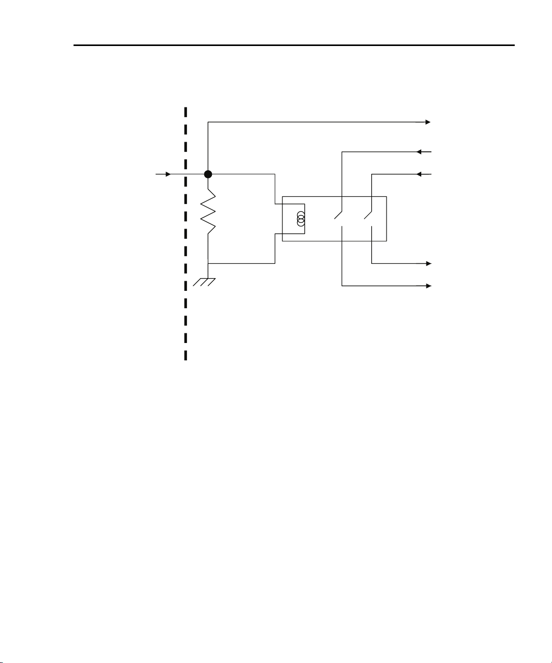
NOTE The Models 2611 and 2612 are equipped with a safety
interlock circuit that prevents operation on the 200V range
if the circuit is not energized. This circuit is illustrated in
Figure 1-4. Refer to Section 10 of the Series 2600 Reference
manual for more information.
Step 6: Make measurements
1. Observe the readings on the display (Press TRIG if necessary to trigger the
unit to begin taking readings.). For the single-channel display mode, the
readings will appear on the top line, while source and limit values are on the
bottom line. For the 10kΩ resistor under test, typical display values are:
1.00000mA
SrcA: +10.0000 V LimA:010.0000mA
Return to In this section: 2600S-900-01 Rev. A / May 2006
Page 24
1-12 Front Panel Operation Series 2600 System SourceMeters User’s Manual
2. Use the DISPLAY key to cycle through the various display modes shown in
Figure 1-5 (The User State display messages are defined with specific
display commands; refer to Section 14 of the Series 2600
Reference manual.).
3. Press the MEAS key several times to display measured voltage, resistance, and power. Typical values for the 10kΩ resistor are: 10.0000V,
10.0000kΩ, and 10.0000mW.
Step 7: Turn output off
When finished making measurements, turn the output off by pressing the
OUTPUT ON/OFF key. The OUTPUT indicator light will turn off.
Figure 1-3
DUT connectio
KEITHLEY SERIES 2600
LO GLO HI G G G HI
ns to 10kΩ resistor
CHANNEL A
SS
HI
DUT 10kW Resistor
LO
2600S-900-01 Rev. A / May 2006 Return to In this section:
Page 25
Series 2600 System SourceMeters User’s Manual Front Panel Operation 1-13
Figure 1-4
Interlock circuit
Read by firmware
INTERLOCK pin
(on DIGITAL I/O connector)
10kW
Chassis ground
Rear panel
Coil resistance
145W +/- 10%
+220V supply
-220V supply
To output stage
Return to In this section: 2600S-900-01 Rev. A / May 2006
Page 26
1-14 Front Panel Operation Series 2600 System SourceMeters User’s Manual
Figure 1-5
Display modes
1.00000mA . V
SrcA:+10.0000V SrcB:+000.000mV
Press DISPLAY key
1.00000mA
SrcA:+10.0000V LimA:10.0000mA
Press DISPLAY key
. V
SrcB:+000.000mV LimB:100.000mA
Press DISPLAY key
User State
Press DISPLAY key
Source-Measure display for SMU A and SMU B:
Top line displays the measure function (V, A, W or W).
Bottom line displays the source function (V or A)
and level.
Source-Measure and Compliance Limit display for SMU A:
Top line displays the measure function (V, A, W or W).
Bottom line displays the source function (V or A) and level,
and the compliance limit (A or V).
Source-Measure and Compliance Limit display for SMU B:
Top line displays the measure function (V, A, W or W).
Bottom line displays the source function (V or A) and level,
and the compliance limit (A or V).
Display for user-defined messages and prompts.
Indicates that a measured reading has not been
triggered.
2600S-900-01 Rev. A / May 2006 Return to In this section:
Page 27

Series 2600 System SourceMeters User’s Manual Front Panel Operation 1-15
How do I use the buffer?
Reference Refer to Section 7 of the Series 2600 Reference Manual for more
detailed information on using the buffer.
The SourceMeter has two buffers per channel that can store from 1 to more than
100,000 readings. Each buffer reading is numbered and can also include the
source value and a timestamp.
The following example shows how to store 100 readings, source values, and
timestamps in Channel A, Buffer 1 and recall them from the front panel.
Step 1: Connect the DUT
Connect a 10kΩ resistor to the Channel A HI and LO terminals (Refer to
Figure 1-3).
Step 2: Set up source and measure functions
Using the procedure described in “How do I make measurements?” earlier in this
section, set-up source and measure functions:
• Source function: volts
• Source range: 20V (2611/2612) or 40V (2601/2602)
• Source value: 10V
• Measure function: current
• Measure range: auto
Step 3: Configure the buffer
1. Press the CONFIG key followed by the STORE key.
2. Choose COUNT, then set the number of readings to store to 100 using the
Rotary Knob, and press ENTER or the Rotary Knob.
3. Select CHANA_BUFF, then press ENTER or the Rotary Knob to select
Channel A.
4. Choose DEST, then CHANA_BUFFER1, and press ENTER or the Rotary
Knob.
5. Choose BUFFER1, then press ENTER or the Rotary Knob to set up Buffer 1.
6. Select CLEAR, then YES to clear the buffer.
7. Choose ELEMENTS, then enable (ON) both SRC-VAL (source value) and
TSTAMP (timestamp) storage.
8. Press EXIT several times to return to normal display.
Return to In this section: 2600S-900-01 Rev. A / May 2006
Page 28

1-16 Front Panel Operation Series 2600 System SourceMeters User’s Manual
Step 4: Turn on the output
Press the CHAN A (Models 2602/2612) OUTPUT ON/OFF key to turn on the
source output.
Step 5: Store readings
1. Press the STORE key to store readings. The asterisk (*) annunciator turns
on to indicate data storage operation is enabled.
2. Press EXIT to stop data storage before it finishes.
Step 6: Turn off the output
Press the OUTPUT ON/OFF key to turn off the output after storage has
completed.
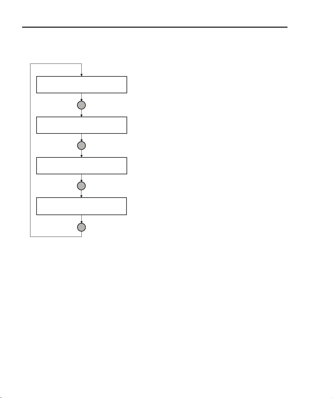
Step 7: Recall readings
1. Press the RECALL key to access buffer readings (repeatedly pressing
RECALL will cycle through Buffer 1 then Buffer 2 for Channel A and then
Channel B). A message will be displayed if a buffer is empty.
2. Note the buffer display data (Refer to Figure 1-6):
• The reading is on the top display at the left.
• The buffer location number is on the right. For example, location
#000001 indicates that the displayed reading is stored at the first
memory location.
• The source value is positioned at the lower left side of the display.
• The timestamp is positioned at the lower right side. The first sourcemeasure reading stored in the buffer (#000001) is timestamped at
00000000.001 seconds. Subsequent readings are timestamped
relative to when the time storage was started. The interval between
readings will depend on the reading rate.
3. To display the other readings stored in the buffer, choose the desired
memory location number:
• Use the Rotary Knob to increment and decrement the selected digit of
the location number.
• Set the cursor position with the Rotary Knob or CURSOR keys.
4. To exit from the data store recall mode, press EXIT.
2600S-900-01 Rev. A / May 2006 Return to In this section:
Page 29
Series 2600 System SourceMeters User’s Manual Front Panel Operation 1-17
Figure 1-6
Buffer display format
Reading
Source Value
(SrcA1=
Channel A,
Buffer 1)
1.00000 mA #0000001
SrcA1:+10.0000 V @00000000.001s
Use Rotary Knob
1.00000 mA #0000002
SrcA1:+10.0000 V @00000000.002s
Use Rotary Knob
1.00000 mA #0000003
SrcA1:+10.0000 V @00000000.003s
Use Rotary Knob
1.00000 mA #0000004
SrcA1:+10.0000 V @00000000.004s
Buffer Location Number
Timestamp (seconds)
Note: Source values and timestamps
will be displayed only if enabled when
buffer is configured.
Return to In this section: 2600S-900-01 Rev. A / May 2006
Page 30

1-18 Front Panel Operation Series 2600 System SourceMeters User’s Manual
This page left blank intentionally.
2600S-900-01 Rev. A / May 2006 Return to In this section:
Page 31

In this Section:
Topic Page
How do I use the remote interface? 2-2
Connect to the interface 2-2
Select the interface 2-3
Configure the interface 2-3
How do I use Test Script Builder? 2-4
Run Test Script Builder 2-4
Open and close an instrument resource 2-7
Save and clear console window 2-8
Select command and language reference views 2-8
How do I use TSB to make measurements? 2-9
Reset instrument 2-10
Select source function and set output value 2-10
Set compliance value and measure range 2-10
Turn on output 2-11
Make a measurement 2-11
Print the result 2-11
Turn off output 2-11
Section 2
Remote Operation
How do I use other programs? 2-12
Using LabVIEW 2-12
Using Visual Basic 2-14
Return to In this Section: 2600S-900-01 Rev. A / May 2006
Page 32

2-2 Remote Operation Series 2600 System SourceMeters User’s Manual
How do I use the remote interface?
Reference Refer to Section 11 of the Series 2600 Reference Manual for
detailed information on communications interfaces.
Step 1: Connect to the interface
Refer to Figure 1-2 in Section 1 of this document for the locations of the GPIB
(IEEE-488) and RS-232 connectors, and make connections as follows:
• GPIB – Use a shielded IEEE-488 cable such as the Keithley Instruments
Model 7007 to connect the Series 2600 IEEE-488 connector to the GPIB
connector on the computer (Refer to
• RS-232 – Use a shielded 9-pin RS-232 cable like the Keithley Instruments
Model 7009-5 to connect the SourceMeter RS-232 connector to the serial
port of the computer (Refer to
Figure 2-1
GPIB cable
Figure 2-1).
Figure 2-2).
GPIB Cable
Connect one end of the cable to the host
Side View Side View
PC and the other end to the SourceMeter.
Both cable connectors are identical.
Figure 2-2
RS-232 cable
Straight-through RS-232 Cable
Male DB-9 Connector
(connect to SourceMeter)
Pin View
Female DB-9 Connector
(connect to PC)
Pin View
2600S-900-01 Rev. A / May 2006 Return to In this Section:
Page 33

Series 2600 System SourceMeters User’s Manual Remote Operation 2-3
Step 2: Select the interface
1. Press MENU to open up the Main Menu.
2. Select COMMUNICATION, then press ENTER.
3. Select INTERFACE_SEL, then press ENTER.
4. Choose GPIB for the IEEE-488 interface, RS-232 for the serial interface, or
AUTO to have the instrument automatically select the interface.
Step 3: Configure the interface
GPIB interface configuration
Set the primary address using the following procedure. The SourceMeter’s
primary address must be the same as that specified in your program, or the two
devices will not be able to communicate.
1. Press MENU to open up the Main Menu.
2. Select COMMUNICATION, then press ENTER.
3. Select INTERFACE_CFG, then press ENTER.
4. Choose GPIB, then press ENTER.
5. Set the GPIB address (0 to 30), and press ENTER.
6. Press EXIT to back out of the menu structure.
RS-232 interface configuration
Set RS-232 parameters as covered below. The Series 2600 RS-232 parameters
must agree with those of the computer serial port, or the two devices will not be
able communicate.
1. Press MENU to open up the Main Menu.
2. Select COMMUNICATION, then press ENTER.
3. Select INTERFACE_CFG, then press ENTER.
4. Choose RS-232, then press ENTER.
5. Configure the RS-232 interface as follows:
• Set the BAUD rate: 300, 600, 1200, 2400, 4800, 9600, 19200, 38400,
57600 or 115200.
• Set BITS: 7 or 8.
• Set PARITY: NONE, ODD, or EVEN.
• Set the FLOW-CTRL: NONE or HARDWARE.
6. Press EXIT to back out of the menu structure.
Return to In this Section: 2600S-900-01 Rev. A / May 2006
Page 34

2-4 Remote Operation Series 2600 System SourceMeters User’s Manual
How do I use Test Script Builder?
Reference Refer to Section 2 of the Series 2600 Reference Manual for com-
plete details on using the Test Script Builder.
Step 1: Run Test Script Builder
Run the Test Script Builder program in the Keithley Instruments folder in the
usual manner. The initial startup screen shown in
The main sections of the screen are briefly described below.
Menu Bar
Main menu items include:
File – Allows you to control projects and files.
Edit – Performs a number of editing functions on script files.
Navigate – Navigates through projects.
Project – Opens, closes, and builds projects.
Run – Runs scripts.
Window – Selects which window to display.
Help – Provides access to online help files.
Figure 2-3 will be displayed.
Project Navigator pane
The window pane on the left side is where the Project Navigator resides. The
navigator consists of created project folders and the script files (.tsp) created for
each project. Each project folder can have one or more script files.
Script Development pane
The script chunk is written in the upper window pane. It is in this area that scripts
are written and/or modified. Notice that there is a tab available for each opened
script file. A script project is then downloaded to the SourceMeter and run.
Sourcemeter/Script Interaction pane
A number of tabs in the lower window pane provide additional interaction between
the Test Script Builder, the SourceMeter and the opened script (the tabs displayed
will depend on those selected in the menu).
2600S-900-01 Rev. A / May 2006 Return to In this Section:
Page 35

Series 2600 System SourceMeters User’s Manual Remote Operation 2-5
Key tabs include:
Instrument Console – The Instrument Console is used to send commands to the
connected SourceMeter. Retrieved data (e.g., readings) from commands and
scripts appear in the console.
Problems – When a script is saved, error checking is performed. If a script error
is detected, an “X” will appear in the script at or near the corrupt line of code. The
Problems tab in the lower window pane will open automatically and provide a
description of the error.
Tasks – When writing a script, a double dash (--) is used to designate that the text
that follows is a comment and not script code. When using the “--TODO” comment
in a script, it will also appear in the Tasks tab, where additional information can be
added.
Command Help – Provides online help to the Instrument Command Library (ICL).
Language Help – Provides online help to the TSL programming language.
Control icons
Control icons (shown in Figure 2-4) include:
1. Open/Close Instrument – Opens instrument resource if closed. Closes
instrument resource if open.
2. Clear Console Window – Clears instrument console window.
3. Abort Execution – Halts execution of commands or scripts.
4. Reset – Aborts whatever the unit is doing and resets everything to the
default state with the output off.
5. Send Software Trigger – Sends a software trigger to take readings.
6. Delete a Script From NVRAM – Brings up a window that lists the scripts
stored in the unit’s non-volatile memory, and allows you to remove scripts.
7. Menu – Accesses the console menu.
8. Minimize/Maximize – Minimizes or maximizes the console window.
Return to In this Section: 2600S-900-01 Rev. A / May 2006
Page 36

2-6 Remote Operation Series 2600 System SourceMeters User’s Manual
Figure 2-3
Test Script Builder i
nitial startup screen
Menu Bar
Script Development Pane
Navigator
Pane
SourceMeter/Script
Interaction Pane
2600S-900-01 Rev. A / May 2006 Return to In this Section:
Control
Icons
Page 37

Series 2600 System SourceMeters User’s Manual Remote Operation 2-7
Figure 2-4
Instrument console control icons
1 2 3 4 5 6 7 8
Step 2: Open and close an instrument resource
Before you can send commands or run scripts to control the SourceMeter, you
must first open the instrument resource as follows:
1. Click on the Open Instrument icon (Refer to Figure 2-4).
2. Choose the desired instrument from the dialog box (Refer to Figure 2-5)
drop-down menu to select a communications resource:
• GPIB – At the factory, the GPIB address for the SourceMeter is set to
26. If using the GPIB interface board 0 and address 26, the resource
setting should be GPIB0::26::INSTR. Resource settings for other GPIB
board numbers and primary addresses are available from the dialog
box.
• RS-232 – Typically, the COM1 serial port of the PC is used for RS-232
communications. For COM1, use the ASRL1::INSTR resource setting.
Resource settings for other COM ports are available from the dialog
box.
Return to In this Section: 2600S-900-01 Rev. A / May 2006
Page 38

2-8 Remote Operation Series 2600 System SourceMeters User’s Manual
3. If you select the Simulate option, the Instrument Console will become
active even though there will be no actual communication with the
SourceMeter. You can simulate running a script or sending a command,
but the SourceMeter will not respond.
4. To close the resource, click on the Instrument icon again. The resource
will close, and the console window will become inactive.
Figure 2-5
Select Instrument Resource dialog box
Step 3: Save and clear console window
You can save and clear the console window as follows:
• Save console – Click on the Menu arrow (Figure 2-3), choose Save
Console, then choose the folder and filename desired.
• Clear console – Click on the Clear Console icon (Figure 2-3) to clear the
console window.
Step 4: Select command and language reference views
You can access online help for the ICL (Instrument Control Library) and TSL (Test
Script Language) as follows:
• ICL: Click on the Command Help tab at the top, then click the Maximize
icon. You can then quickly get information on all commands in the library.
• TSL: Click on the Language Help tab at the top, then click the Maximize
icon to quickly access details on the script language.
2600S-900-01 Rev. A / May 2006 Return to In this Section:
Page 39

Series 2600 System SourceMeters User’s Manual Remote Operation 2-9
How do I use TSB to make measurements?
Reference Refer to “Remote source-measure procedure” in Sections 4 and 12
of the Series 2600 Reference Manual for details on instrument commands.
The following procedure uses the TSB Instrument Console to send commands to
source voltage and measure current on Channel A using a 10kΩ resistor as the
DUT. The complete command sequence as it would appear in the console win
dow is shown in Figure 2-6, along with instrument responses.
Figure 2-6
Source-measure command sequence in console window
Reset SourceMeter
Select volts function
Set source range to 40V
Set source level to 10V
Set current limit to 10mA
Set measure range to 10mA
Turn on output
Take current reading
Print current reading
Instrument response
Print resistance reading
Instrument response
Print power reading
Instrument response
Turn off output
(2601/2602 version shown)
-
Return to In this Section: 2600S-900-01 Rev. A / May 2006
Page 40

2-10 Remote Operation Series 2600 System SourceMeters User’s Manual
The procedure assumes the DUT (10kΩ resistor) is already connected to the
SourceMeter (
resource has already been opened (“Open and close an instrument resource”
earlier in this section).
WARNING Hazardous voltages may be present on the output and guard
Figure 1-3 in Section 1 of this manual), and that the instrument
terminals. To prevent electrical shock that could cause injury
or death, NEVER make or break connections to the Series 2600
while the output is on. Power off the equipment from the front
panel or disconnect the main power cord from the rear of the
SourceMeter before handling cables connected to the outputs.
Putting the equipment into standby does not guarantee the
outputs are not powered if a hardware or software fault occurs.
Step 1: Reset instrument
A good practice is to reset the instrument to its default settings before the start of
a test. To reset the SourceMeter, type the following command into the console
window, then press the Return key:
reset()
For Model 2602 or 2612, you can restore defaults of Channel A or Channel B
respectively as follows:
smua.reset()
smub.reset()
Step 2: Select source function and set output value
Enter the following commands to select the source voltage function, set the
source range to 20V (Models 2611/2612) or 40V Models 2601/2602), and set the
source value to 10V:
smua.source.func = smua.OUTPUT_DCVOLTS
smua.source.rangev = 40 (use for Models 2601/2602)
smua.source.rangev = 20 (use for Models 2611/2612)
smua.source.levelv = 10
Step 3: Set compliance value and measure range
Enter the following commands to set the compliance limit and measure range to
10mA:
smua.source.limiti = 10e-3
smua.measure.rangei = 10e-3
2600S-900-01 Rev. A / May 2006 Return to In this Section:
Page 41

Series 2600 System SourceMeters User’s Manual Remote Operation 2-11
Step 4: Turn on output
Send the following command to turn on the output:
smua.source.output =smua.OUTPUT_ON
Step 5: Make a measurement
Enter the following command to take a current measurement:
reading = smua.measure.i()
Step 6: Print the result
Print the result in the console window with the following command:
print(reading)
Note that the reading response will appear in the console window (refer to
Figure 2-6).
Alternatively, you can take and print readings by including the appropriate mea-
sure command as the argument in the print command. For example, the following commands will take and print ohms and power readings respectively:
print(smua.measure.r())
print(smua.measure.p())
Again, readings will be displayed in the console window.
Step 7: Turn off output
Send the following command to turn off the output when measurements are
complete:
smua.source.output =smua.OUTPUT_OFF
Return to In this Section: 2600S-900-01 Rev. A / May 2006
Page 42

2-12 Remote Operation Series 2600 System SourceMeters User’s Manual
How do I use other programs?
Reference Refer to the LabVIEW and Visual Basic documentation for details
on using those programs.
Basic source-measure examples using LabVIEW and Visual Basic are shown
below. Refer also to also Section 3 for more examples of how to load and
run scripts.
Using LabVIEW
The source-measure example using LabVIEW is shown in Figure 2-7. The test
steps are:
1. Reset instrument.
2. Select source voltage function.
3. Set source output voltage.
4. Turn on output.
5. Take current measurement.
6. Reset instrument.
The command sequence for this source-measure example is shown below:
localnode.prompts = 0 --Disable prompts.
reset() -- Reset Series 2600.
smua.source.func =
smua.OUTPUT_DCVOLTS
smua.source.levelv = volts --Set voltage source level.
smua.source.output = smua.OUTPUT_ON -- Turn on source output.
print(smua.measurei()) -- Take and return current reading.
reset() -- Reset Series 2600.
2600S-900-01 Rev. A / May 2006 Return to In this Section:
--Select voltage source function.
Page 43

Series 2600 System SourceMeters User’s Manual Remote Operation 2-13
Figure 2-7
LabVIEW source-measure example block diagram
Return to In this Section: 2600S-900-01 Rev. A / May 2006
Page 44

2-14 Remote Operation Series 2600 System SourceMeters User’s Manual
Using Visual Basic
User interface
The GUI (graphical user interface) shown in Figure 2-8 was created to
demonstrate how to control a Keithley Instruments Series 2600 SourceMeter
using Visual Basic 6.0. Source code for this example program can be downloaded
from the Keithley Instruments internet site, www.keithley.com.
Figure 2-8
Visual Basic example user interface
2600S-900-01 Rev. A / May 2006 Return to In this Section:
Page 45

Series 2600 System SourceMeters User’s Manual Remote Operation 2-15
Using the Series 2600 as a traditional GPIB instrument
The following pseudocode describes how the Series 2600 will be configured and
controlled to source voltage and measure current for this example. Some of the
settings are default values restored by resetting the instrument, but they are
included to show a typical setup and measure sequence that might be used for
such a test.
1. Reset SourceMeter to default settings.
2. Set display to show SMU A source and limit settings.
3. Set display to show current measurement.
4. Set source function to DCV.
5. Enable source autorange.
6. Set source level to 5V.
7. Set current compliance to 100mA.
8. Set current measurement range to 100mA.
9. Set integration time to 1PLC.
10. Turn on SMU A output.
11. Measure the current and put reading in instrument output queue. This step
is similar to using a SCPI “READ?” query to take a single reading.
12. Turn off SMU A output.
Command sequence
The commands that implement the pseudocode are listed below. The syntax for
the “send” and “enter” commands is for a Keithley Instruments GPIB card. To use
a Keithley Instruments GPIB card in Visual Basic, you must include the
“ieeevb.bas” module in your project. This module is included on the CD that
comes with your GPIB card.
When you click the “Run with GPIB” button on the GUI, the commands are sent to
the Series 2600 and executed. The single reading returned by these commands is
displayed in the Data text box as shown in
Return to In this Section: 2600S-900-01 Rev. A / May 2006
Figure 2-9.
Page 46

2-16 Remote Operation Series 2600 System SourceMeters User’s Manual
Note: Addr% is the GPIB address of the instrument and is assigned the value of 26
Call send(Addr%, "localnode.prompts = 0", intStatus)
Call send(Addr%, "reset()", intStatus)
Call send(Addr%, "display.screen = display.SMUA", intStatus)
Call send(Addr%, "display.smua.measure.func = display.MEASURE_DCAMPS", intStatus)
Call send(Addr%, "smua.source.func = smua.OUTPUT_DCVOLTS", intStatus)
Call send(Addr%, "smua.source.autorangev = smua.AUTORANGE_ON", intStatus)
Call send(Addr%, "smua.source.levelv = 5", intStatus)
Call send(Addr%, "smua.source.limiti = 0.1", intStatus)
Call send(Addr%, "smua.measure.rangei = 0.1", intStatus)
Call send(Addr%, "smua.measure.nplc = 1", intStatus)
Call send(Addr%, "smua.source.output = smua.OUTPUT_ON", intStatus)
Call send(Addr%, "print(smua.measure.i())", intStatus)
Call send(Addr%, "smua.source.output = smua.OUTPUT_OFF", intStatus)
Call enter(strBuffer, 256, intNbytes, Addr%, intStatus)
txtData.Text = strBuffer
Figure 2-9
Example program test results
2600S-900-01 Rev. A / May 2006 Return to In this Section:
Page 47

Series 2600 System SourceMeters User’s Manual Remote Operation 2-17
Using VISA
Clicking on the “Run with VISA” button will send the same commands to the
Series 2600 using NI VISA. The VISA resource is for an instrument at address 26
connected to GPIB interface #1. Once again, a Keithley Instruments GPIB card
was used for this example. However, VISA allows the same code to be used with
GPIB cards made by other manufacturers, or with altogether different interfaces
such as the RS-232 or the Ethernet.
Return to In this Section: 2600S-900-01 Rev. A / May 2006
Page 48

2-18 Remote Operation Series 2600 System SourceMeters User’s Manual
This page left blank intentionally.
2600S-900-01 Rev. A / May 2006 Return to In this Section:
Page 49

In this section:
Topic Page
What is a script? 3-2
Factory scripts 3-2
User scripts 3-2
How do I run a script from the front panel? 3-2
How do I interact with scripts using Test Script Builder? 3-3
Running a factory script 3-4
Modifying a factory script 3-6
Running the user script 3-12
Deleting a user script and user tests 3-13
How do I use other programs? 3-14
Using LabVIEW 3-14
Using Visual Basic 3-16
Section 3
Test Script Processor Interaction
Return to In this section: 2600S-900-01 Rev. A / May 2006
Page 50

3-2 Test Script Processor Interaction Series 2600 System SourceMeters User’s Manual
What is a script?
Reference Refer to “Programming overview” in Section 2 of the Reference
Manual for more information on script fundamentals.
A script is a collection of instrument control commands and programming
statements to perform one or more operations or tasks. A script is stored in a
Series 2600 and is run by its Test Script Processor (TSP).
Factory scripts
The Series 2600 is shipped from the factory with at least one factory script stored
in it’s non-volatile memory. Each factory script is made up of a series of functions
to perform specific tests. A factory script function can be called (run) from the front
panel or called using remote programming. A factory script cannot be deleted
from non-volatile memory.
User scripts
A user script is a script created by a user using the Test Script Builder or an
external program. The user script is loaded in the Series 2600 and stored in
volatile or non-volatile memory. If stored in non-volatile memory, the script will not
be lost when the instrument is turned off.
Keithley Instruments will be posting approved user scripts donated by registered
users on its web site. You will be able to download these user scripts into your
Series 2600. Visit www.keithley.com for details.
How do I run a script from the front panel?
Reference Refer to “Factory scripts” and “User Scripts” in Section 2 of the
Series 2600 Reference Manual for details on running scripts.
From the front panel, all factory script functions are interactive. That is, when the
test is started, the operator will be prompted to enter test parameters. A user
script may, or may not be interactive. A non-interactive script requires no operator
input and will run to completion when it is started.
NOTE If the Series 2600 is in remote operation, press the LOCAL
key to return control to the front panel.
1. Press the LOAD key to display the LOAD TEST menu.
2600S-900-01 Rev. A / May 2006 Return to In this section:
Page 51

Series 2600 System SourceMeters User’s Manual Test Script Processor Interaction 3-3
2. Position the blinking cursor on the FACTORY or USER menu item and press
ENTER (or the Rotary Knob). Keep in mind that the Series 2600 is shipped
with no user scripts loaded.
3. Position the blinking cursor on the test to be run, and then press ENTER.
4. Press the RUN key to start the test.
5. Enter required test parameters using the front panel controls.
Reading the buffer – Test data is stored in a buffer. Refer to in Section 1 of this
manual, “
How do I use the buffer?” for details on recalling test data.
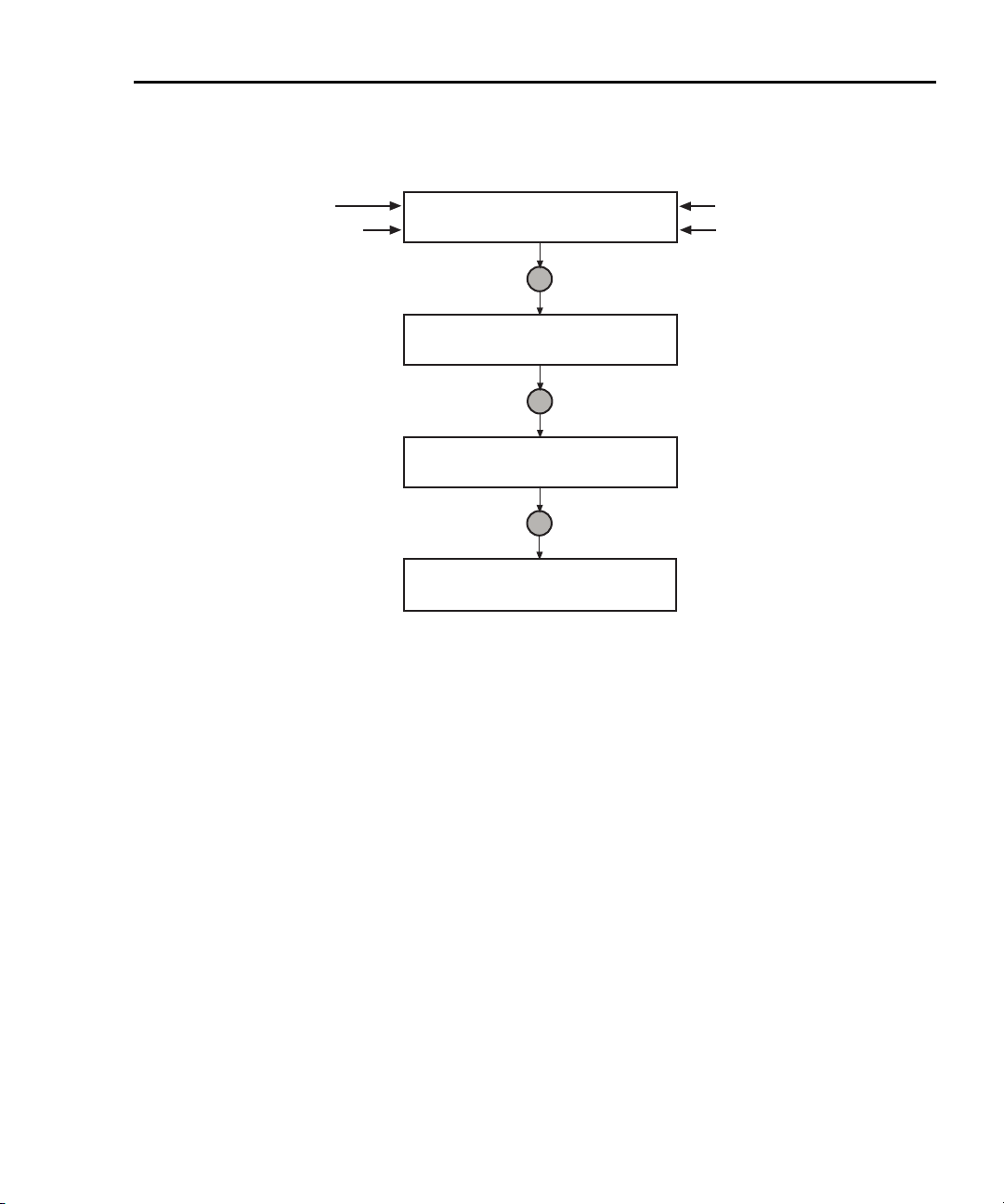
How do I interact with scripts using Test Script Builder?
Reference Refer to “Using the Test Script Builder” in Section 2 of the Series
2600 Reference Manual for details on the Test Script Builder.
The following function for factory script “KIGeneral” is stored in the non-volatile
memory of the Series 2600:
PulseVMeasureI(smu, bias, level, ton, toff, points)
The above function performs a specified number of pulse V, measure I cycles:
• Sets the smu to output bias volts and dwell for ton seconds.
• Sets the smu to output level volts and dwell for ton seconds.
• Performs current measurement with the source at level volts.
• Sets the smu to output bias volts for toff seconds.
• Repeats the above sequence for points pulse-measure cycles.
Figure 3-1 shows one pulse-measure cycle for the function.
Figure 3-1
Pulse-measure cycle for the
level
bias
ton toff
ton
Return to In this section: 2600S-900-01 Rev. A / May 2006
PulseVMeasureI function
Current measurement
bias
Page 52

3-4 Test Script Processor Interaction Series 2600 System SourceMeters User’s Manual
Running a factory script
Reference Refer to “Factory scripts” in Section 2 of the Series 2600 Reference
Manual for details on running factory scripts.
NOTE All commands to run a factory script are to be executed
from the Instrument Console of the Test Script Builder.
The following steps explain how to run the PulseVMeasureI function and read
the data stored in the buffer.
NOTE The “KIGeneral” factory script is an autorun script. The
script runs automatically when the Series 2600 is turned on.
The functions of the script are ready to be called.
Step 1: Call the function
The following are example parameters for the PulseVMeasureI function which
will perform three pulse voltage, measure current cycles:
smu = SMU A level = 1V toff = 2ms
bias = -1V ton = 1ms points = 3
The following command will execute the PulseVMeasureI function using the
above parameters:
PulseVMeasureI(smua, -1, 1, 1E-3, 2E-3, 3)
Step 2: Read the buffer
Reference Refer to Section 7 of the Series 2600 Reference Manual for details
on the reading buffers.
The above function stores the three current measurements in the reading buffer
smua.nvbuffer1). Also stored in the buffer are the voltage source settings and
(
timestamps for the measurements. The timestamps (in seconds) are referenced
to the start of the test. The timer for the timestamps starts at zero seconds when
the test is started.
The printbuffer function is used to print (output) measured readings,
timestamps and/or source values stored in the buffers.
Print readings – The following code will return the three measured current
readings stored in
rb1 = smua.nvbuffer1
printbuffer(1, rb1.n, rb1)
Example output: 1.234567e-03, 2.362360e-03, 2.362368e-03
For the above printbuffer function, 1 is the starting index for values to print,
rb1.n is the ending index (for this function, n = 3), and rb1 is the reading buffer
smua.nvbuffer1).
(
2600S-900-01 Rev. A / May 2006 Return to In this section:
nvbuffer1:
Page 53

Series 2600 System SourceMeters User’s Manual Test Script Processor Interaction 3-5
Print timestamps – The following command will print the timestamps for the
three measured current readings:
printbuffer(1, rb1.n, rb1.timestamps)
Example output: 5.555555e-02, 8.888888e-02, 1.111111e-01
Print source values – The following command will print the voltage source values for the three measured current readings:
printbuffer(1, rb1.n, rb1.sourcevalues)
Output: 1.000000e+00, 1.000000e+00, 1.000000e+00
Print readings, timestamps and source values – The following command will
return the three sets of data (nine values) in the same message:
printbuffer(1, rb1.n, rb1, rb1.timestamps, rb1.sourcevalues)
Example output:
1.234567e-03, 5.555555e-02, 1.000000e+00, 2.362360e-03,
8.888888e-02, 1.000000e+00, 2.362368e-03, 1.111111e-01,
1.000000e+00
The above output is returned in the following order:
reading1, timestamp1, sourcevalue1, reading2, timestamp2, sourcevalue2,
reading3, timestamp3, sourcevalue3
Calling a function without parameters
When the command to call a script function is sent without parameters, input
value fields and messages will appear on the display to prompt the operator to
input the parameters using the front panel controls.
The following command will call the SourceVMeasureI function and then require
operator interaction:
PulseVMeasureI()
After sending the above command, the Series 2600 display will prompt the
operator to input the following parameters from the front panel:
• Enter BIAS voltage.
• Enter PULSE (level) voltage.
• Enter pulse ON time.
• Enter pulse OFF time.
• Enter number of pulses (points).
After the operator keys in each parameter and presses the ENTER key (or the
Rotary Knob), the display will proceed to the next input prompt. After the last
parameter (number of pulses) is entered, the test will continue.
The following message will be displayed when the test is finished:
PulseVMeasureI
Test complete.
Return to In this section: 2600S-900-01 Rev. A / May 2006
Page 54

3-6 Test Script Processor Interaction Series 2600 System SourceMeters User’s Manual
Modifying a factory script
Reference Refer to “Factory scripts” in Section 2 of the Series 2600 Reference
Manual for more information on modifying a factory script.
A factory script can be imported from the Series 2600 into the Test Script Builder
where it can be modified. The modified script can then be loaded back into the
Series 2600 and saved as a user script.
The following procedure will import the KIGeneral factory script into the Test
Script Builder, modify code for the SourceVMeasureI function, load the script in
the Series 2600 as a user script under a different name, and then configure the
test to call the SourceVMeasureI function.
Step 1: Importing a factory script project
A factory script project is made of many executable functions. The
SourceVMeasureI function is one of the functions that make up the KIGeneral
factory script that is stored in the Series 2600.
Figure 3-2 shows how to import the KIGeneral factory script project from the
Series 2600 into the Test Script Builder. After importing the script, the project will
appear as a folder in the Project Navigator with a script file named “main.tst”
(Refer to
Figure 3-3).
2600S-900-01 Rev. A / May 2006 Return to In this section:
Page 55

Series 2600 System SourceMeters User’s Manual Test Script Processor Interaction 3-7
Figure 3-2
Importing a factory script project from the Series 2600
A) Click File to display the drop-down file menu
and click Import to open the Import wizard.
B) In the Import Select box, click Existing Project
From Instrument and then click Next.
C) In the Import Project From Instrument box, click
the KIGeneral project, and then click Finish.
KIGeneral
KIGeneral
Return to In this section: 2600S-900-01 Rev. A / May 2006
Page 56

3-8 Test Script Processor Interaction Series 2600 System SourceMeters User’s Manual
Figure 3-3
KIGeneral project imported into the Test Script Builder
Test Code
Project Navigator
Step 2: Modifying the test code for the SourceVMeasureI function
As shown in Figure 3-3, the test code for the script functions is contained in the
tab for the “main.tsp” script file. The test code for all of the functions of the
KIGeneral factory script are in this tab. Use the scroll buttons on the right side of
the tab to view more code.
Editing example
The following line of code in the “main.tsp” script file applies to the
SourceVMeasureI function:
92 bias = display.prompt("+00.000", " Seconds", "Enter
BIAS Voltage.", 0, -40, 40)
The above command defines a display input field and message prompt for
entering the bias voltage. The
be entered, and the
2600S-900-01 Rev. A / May 2006 Return to In this section:
40 parameter sets the maximum voltage that can be entered.
-40 parameter sets the minimum voltage that can
Page 57

Series 2600 System SourceMeters User’s Manual Test Script Processor Interaction 3-9
Now assume you wish to change the bias input limits to ±10V. Edit the line of
code to the following:
92 bias = display.prompt("+00.000", " Seconds", "Enter
BIAS Voltage.", 0, -10, 10)
Saving the script – After modifying the script file, it must be saved by clicking the
save icon on the toolbar of the Test Script Builder as follows:
Click to save the main.tsp script file
Step 3: Storing the script in non-volatile memory of the Series 2600
Reference Refer to “User scripts” in Section 2 of the Series 2600 Reference
Manual for more information on storing user scripts in non-volatile
memory.
After modifying a factory script, it can be loaded back into the Series 2600 and
saved in non-volatile memory as a user script.
1. The Run configuration box is used to launch (load) a user script into the
Series 2600 and save it in non-volatile memory. As shown below, open the
Run box and then click Run in the drop-down menu:
Click Run and then click Run
in the drop-down menu.
Return to In this section: 2600S-900-01 Rev. A / May 2006
Page 58

3-10 Test Script Processor Interaction Series 2600 System SourceMeters User’s Manual
NOTE Figure 3-4 and 7. show how the Run box will look after the
launch is configured.
Figure 3-4
Run configuration example - Main tab shown
Changing the script Name from KIGeneral to KIGeneralUser
also changes the name in the Configurations area.
2. In the Configurations area of the Run box, select the KIGeneral script. The
launch configuration tabs for that script will appear in the Run box.
3. Presently, the Name of the script is KIGeneral. You should change the name
so the script is not confused with the factory script of the same name that
resides in the Series 2600. Change the script Name to KIGeneralUser and
click the Apply button.
2600S-900-01 Rev. A / May 2006 Return to In this section:
Page 59

Series 2600 System SourceMeters User’s Manual Test Script Processor Interaction 3-11
4. As shown in Figure 3-4, the main.tsp file must be in the Load Order area of
the Run box. If it is in the Available Project Files area, double-click main.tsp to
move the file over.
Figure 3-5
Run configuration example - Script Attributes tab shown
5. Click the Script Attributes tab to display the load and store options and select
the LoadOnly run action and Non-volatile storage as shown in
7..
6. Click the Apply button to set the run configuration.
7. Click the Run key to load the user script into non-volatile memory of the
Series 2600.
NOTE There is small bar graph at the bottom-right of the Test
Script Builder that will appear while a script is loading. The
bar graph will continuously sequence through its segments
while the script is loading.
Return to In this section: 2600S-900-01 Rev. A / May 2006
Page 60

3-12 Test Script Processor Interaction Series 2600 System SourceMeters User’s Manual
Running the user script
Reference Refer to “User scripts” in Section 2 of the Series 2600 Reference
Manual for details on running a user script.
Remote programming
The functions for the KIGeneralUser user script can be called after the script is run
as follows:
KIGeneralUser()
After the above command is executed, any of the functions that make up the user
script can be called in the same manner that factory script functions are called
(refer to “
Front panel operation
To run the script from the front panel, a test name has to be added to the USER
TESTS submenu of the LOAD TEST menu. Since the KIGeneralUser script is
made up of eight functions, a front panel user test must run the script and also call
a function. The following command will add the test name “PulseVMeasI” to the
menu. It will also configure the test to run the
PulseVMeasureI function:
display.loadmenu.add("PulseVMeasI", "KIGeneralUser()
PulseVMeasureI()", display.SAVE)
Step 1: Call the function”).
KIGeneralUser script and call the
Since no parameters are used in the function (PulseVMeasureI()), the test will
be interactive and require the operator to input the test parameters using the front
panel controls. Refer to “
earlier in this section for details on running a user script from the front panel.
The command display.loadmenu.add can be used to configure front panel
user tests for the other functions of the script. Make sure to use a different menu
name for each function. For example, the following command will add the name
“PulseIMeasV” for a test to call the
display.loadmenu.add("PulseIMeasV", "KIGeneralUser()
PulseIMeasureV()", display.SAVE)
Reference Refer to “Load test menu” in Section 14 of the Series 2600 Refer-
ence Manual for details on the
2600S-900-01 Rev. A / May 2006 Return to In this section:
How do I run a script from the front panel?” described on
PulseIMeasureV function.
display.loadmenu.add function.
Page 61

Series 2600 System SourceMeters User’s Manual Test Script Processor Interaction 3-13
Deleting a user script and user tests
Deleting a user script
A user script can be deleted from non-volatile memory of the Series 2600. The
following command will delete the
script.delete("KIGeneralUser")
Deleting a user test
After deleting a script, you should also delete the test from the USER TESTS
menu since it no longer exists. The following command deletes the “PulseVMeasI”
test from the menu:
display.loadmenu.delete("PulseVMeasI")
Reference Refer to “User scripts” in Section 2 of the Series 2600 Reference
Manual for more information on deleting a user script. Refer to
“Load test menu” in Section 14 of the Reference Manual for details
on deleting user tests from the front panel USER TESTS menu.
KIGeneralUser user script:
Return to In this section: 2600S-900-01 Rev. A / May 2006
Page 62

3-14 Test Script Processor Interaction Series 2600 System SourceMeters User’s Manual
How do I use other programs?
Reference Refer to the LabVIEW and Visual Basic documentation for details
on using those programs.
Using LabVIEW
Source step example
The source step example is shown in Figure 3-6. The example steps the source
voltage from 1V to 10V in 1V steps, measures the current at each step, and stores
the result in a table. Once all steps are completed, the stored table current values
are printed.
The Series 2600 command sequence:
localnode.prompts = 0 -- Disable prompts.
data_table = {} -- Clear table.
reset() -- Reset Series 2600.
smua.source.output = 1 -- Turn on source output.
for i=1,10 do -- Loop for 10 steps.
smua.source.levelv = i -- Set source level.
mi = smua.measure.i() -- Take a current measurement.
table.insert(data_table,mi) -- Store measurement in table.
end -- End of loop.
smua.source.output = 0 -- Turn off output.
print(table.concat(data_table,’,’)) -- Print table of current values.
reset() -- Reset instrument.
2600S-900-01 Rev. A / May 2006 Return to In this section:
Page 63

Series 2600 System SourceMeters User’s Manual Test Script Processor Interaction 3-15
Figure 3-6
LabVIEW source step example
Return to In this section: 2600S-900-01 Rev. A / May 2006
Page 64

3-16 Test Script Processor Interaction Series 2600 System SourceMeters User’s Manual
Using Visual Basic
NOTE The form file (UserManualExample.frm) can be opened
using any text editor to view the code executed by the
various command buttons.
The following examples look at how you can download and run Model 2600
Series scripts using Visual Basic. Two scripts were created for these examples.
Both scripts are based on the pseudocode and instrument commands presented
Section 2 on using the Series 2600 as a traditional GPIB instrument while multi-
in
ple measurements are performed. Source code for this example program can be
downloaded from the Keithley Instruments internet site, www.keithley.com.
Example script 1 – script that does not use functions
The following script is in the file named “MeasCurrScript.tsp.” Note that the actual
script contains additional comments, which have not been included here.
Comments are identified by double dashes (--).
reset()
display.screen = display.SMUA
display.smua.measure.func = display.MEASURE_DCAMPS
smua.source.func = smua.OUTPUT_DCVOLTS
smua.source.autorangev = smua.AUTORANGE_ON
smua.source.levelv = 5
smua.source.limiti = 0.1
smua.measure.rangei = 0.1
smua.measure.nplc = 1
smua.source.output = smua.OUTPUT_ON
ntimes = 10
for i = 1, ntimes do -- Perform following command(s) ntimes.
print(smua.measure.i()) -- Measure current and put reading in
output queue.
end --for
smua.source.output = smua.OUTPUT_OFF
The primary code that reads the file and downloads the script to the Series 2600
is listed below. This code is executed when you select the Load “Non-Function”
Script option, and then click the Load Script (GPIB) command button. Although
not required, TSP prompts are enabled for this example because they provide
useful test script processor status information when loading and running scripts.
Refer to the Series 2600 System SourceMeter Instruments Reference Manual for
more information about using prompts. As the script is being downloaded, it is
displayed in the Script text box of the GUI (Graphical User Interface), as shown in
Figure 3-7.
2600S-900-01 Rev. A / May 2006 Return to In this section:
Page 65

Series 2600 System SourceMeters User’s Manual Test Script Processor Interaction 3-17
Figure 3-7
GUI after loading the non-function script (GPIB)
Return to In this section: 2600S-900-01 Rev. A / May 2006
Page 66

3-18 Test Script Processor Interaction Series 2600 System SourceMeters User’s Manual
Call send(Addr%, "localnode.showerrors =
0", intStatus)
Call send(Addr%, "localnode.prompts = 1",
intStatus)
strReturnMessage = udfGetTspResponse()
Open App.Path & "\" & "MeasCurrScript.tsp" For Input As #1
Call send(Addr%, "loadscript MeasCurrScript", intStatus)
strReturnMessage = udfGetTspResponse()
Do While Not EOF(1)
Line Input #1, strScriptline
Call send(Addr%, strScriptline, intStatus)
strReturnMessage = udfGetTspResponse()
strReturnMessage = Left(strReturnMessage,
4)
Select Case strReturnMessage
Case ">>>>"
--Disable automatic display of errors - leave
error messages in queue and enable
Error Prompt. The "localnode" unit is
being communicated with via GPIB or RS-
232.
--Turn on prompts; need to start handling
the prompts as soon as this command
is sent.
--Open the script file for sequential input.
--
“loadscript” identifies the beginning of the
script.
“MeasCurrScript” is the name assigned to
the script.
--
Read the file.
--
Loop until the end of the script file.
--
Read a line from the script file
--
Send script line to Series 2600
--
Continuation prompt.
TSP received script line successfully;
waiting for next line.
Case "TSP>"
--
Ready prompt.
TSP received script successfully; ready
for next command.
Exit Do
Case "TSP?"
--
Error prompt.
Error occurred; handle as desired.
Use “errorqueue” commands to read and
clear errors.
Case Else
--
No prompt received.
Response other than shell prompt was
received; handle as desired.
End Select
Loop
Close #1
Call send(Addr%, "endscript", intStatus)
strReturnMessage = udfGetTspResponse()
2600S-900-01 Rev. A / May 2006 Return to In this section:
--
Close the script file.
--
Tell TSP complete script has been downloaded.
Page 67

Series 2600 System SourceMeters User’s Manual Test Script Processor Interaction 3-19
Call send(Addr%, "localnode.prompts = 0",
intStatus)
--
The primary code that runs the script and retrieves the measurement results is
listed below. This code is executed when you click the Run Script (GPIB)
command button. When you run this script it will perform ten measurements and
send the readings to the PC. The results are displayed in the Data text box of the
GUI as shown in
Figure 3-8. TSP prompts are enabled prior to running the script
The following command runs the script; can also use "MeasCurrScript()" form of
the command
Call send(Addr%, "MeasCurrScript.run()",
intStatus)
Do
strReturnMessage = udfGetTspResponse()
txtData.Text = txtData.Text & strReturnMessage
Loop Until Left(strReturnMessage, 3) = "TSP"
If strReturnMessage = "TSP?" Then
txtStatusDesc.Text = "Error Occurred"
Call send(Addr%, "print(errorqueue.next()",
intStatus)
strReturnMessage = udfGetTspResponse()
txtStatusDesc.Text = txtStatusDesc.Text & strReturnMessage &
vbCrLf
End If
Disable prompts.
--Get output from script.
Return to In this section: 2600S-900-01 Rev. A / May 2006
Page 68

3-20 Test Script Processor Interaction Series 2600 System SourceMeters User’s Manual
Figure 3-8
GUI after running the non-function script (GPIB)
Example script 2 – script that uses functions
The script used in this example is in the file named “MeasCurrFunctionScript.tsp.”
This script is downloaded to the Series 2600 by selecting the Load “Function”
Script option, and then clicking the Load Script (GPIB) command button. The
script is downloaded exactly as shown in the previous example, except the “open
file” and “loadscript” commands reflect the different script name, as shown below.
Open App.Path & "\" & "MeasCurrFunctionScript.tsp" For Input As #1
Call send(Addr%, "loadscript MeasCurrFunctionScript", intStatus)
The other difference is in the script itself, which is listed below. This script does
not perform multiple current measurements, but rather it creates a function named
“MeasCurr,” which performs one or more current measurements when it is called.
The number of measurements depends on the value of “ntimes,” which is passed
2600S-900-01 Rev. A / May 2006 Return to In this section:
Page 69

Series 2600 System SourceMeters User’s Manual Test Script Processor Interaction 3-21
to the function when it is called. Figure 3-9 shows the GUI (Graphical User
Interface) after loading and running the script. Note that the Data text box does
not contain any readings as in the previous example; it simply indicates that the
“MeasCurr(ntimes)” function has been created.
function MeasCurr(ntimes)
local l_i -- Local counter variable
reset()
display.screen = display.SMUA
display.smua.measure.func = display.MEASURE_DCAMPS
smua.source.func = smua.OUTPUT_DCVOLTS
smua.source.autorangev = smua.AUTORANGE_ON
smua.source.levelv = 5
smua.source.limiti = 0.1
smua.measure.rangei = 0.1
smua.measure.nplc = 1
smua.source.output = smua.OUTPUT_ON
for l_i = 1, ntimes do
print(smua.measure.i())
end --for
smua.source.output = smua.OUTPUT_OFF
end --function
print("Function 'MeasCurr(ntimes)' created")
Return to In this section: 2600S-900-01 Rev. A / May 2006
Page 70

3-22 Test Script Processor Interaction Series 2600 System SourceMeters User’s Manual
Figure 3-9
GUI after loading and running the function script (GPIB)
2600S-900-01 Rev. A / May 2006 Return to In this section:
Page 71

Series 2600 System SourceMeters User’s Manual Test Script Processor Interaction 3-23
The primary code that calls the function and retrieves the measurement results is
listed below. TSP prompts are enabled prior to calling the function. This code is
executed when you click the Call Function (GPIB) command button. In this
example, the function performs ten current measurements and sends the
readings to the PC because “ntimes” is set to 10 when the function is called. The
results are displayed in the Data text box as shown in
Figure 3-10. Note that it
would be just as easy to take one or 100 readings simply by calling the function
with a different value for “ntimes,” for example, MeasCurr(100). You can pass
parameters to a function, but not to a script. However, you must initially run a
script to create a function. Refer to the Series 2600 Reference Manual for more
information about scripts and functions.
Call send(Addr%, "MeasCurr(10)", intStatus)
--Call function with ntimes=10
and then enter data.
Do
strReturnMessage = udfGetTspResponse()
txtData.Text = txtData.Text & strReturnMessage &
vbCrLf
Loop Until Left(strReturnMessage, 3) = "TSP"
If strReturnMessage = "TSP?" Then
txtStatusDesc.Text = "Error Occurred"
Call send(Addr%, "print(errorqueue.next()",
intStatus)
strReturnMessage = udfGetTspResponse()
txtStatusDesc.Text = txtStatusDesc.Text & strReturnMessage & vbCrLf
--Get output from function.
End If
--Take appropriate action
based on error message.
Return to In this section: 2600S-900-01 Rev. A / May 2006
Page 72

3-24 Test Script Processor Interaction Series 2600 System SourceMeters User’s Manual
Figure 3-10
GUI after calling the function (GPIB)
2600S-900-01 Rev. A / May 2006 Return to In this section:
Page 73

Section 4
Controlling Multiple SourceMeters (TSP-Link)
In this section:
Top ic
How do I set up the TSP-Link system?
Connect the TSP-Link system
Assign node numbers 4-2
Reset the TSP-Link 4-3
Check the state of the TSP-Link system
How do I use the expanded system? 4-4
Accessing resources of TSP-Link nodes 4-4
Using node[N]
Using the alias (localnode) 4-4
Running scripts in a TSP-Link system 4-5
Page
4-2
4-2
4-4
4-4
Return to In this section: 2600S-900-01 Rev. A / May 2006
Page 74

4-2 Controlling Multiple SourceMeters Series 2600 System SourceMeters User’s Manual
WARNING:NO INTERNAL OPERATOR SERVICABLE PARTS,SERVICE BY QUALIFIED PERSONNEL ONLY.
WARNING:NO INTERNAL OPERATOR SERVICABLE PARTS,SERVICE BY QUALIFIED PERSONNEL ONLY.
CAUTION:FOR CONTINUED PROTECTION AGAINST FIRE HAZARD,REPLACE FUSE WITH SAME TYPE AND RATING.
CAUTION:FOR CONTINUED PROTECTION AGAINST FIRE HAZARD,REPLACE FUSE WITH SAME TYPE AND RATING.
WARNING:NO INTERNAL OPERATOR SERVICABLE PARTS,SERVICE BY QUALIFIED PERSONNEL ONLY.
WARNING:NO INTERNAL OPERATOR SERVICABLE PARTS,SERVICE BY QUALIFIED PERSONNEL ONLY.
CAUTION:FOR CONTINUED PROTECTION AGAINST FIRE HAZARD,REPLACE FUSE WITH SAME TYPE AND RATING.
CAUTION:FOR CONTINUED PROTECTION AGAINST FIRE HAZARD,REPLACE FUSE WITH SAME TYPE AND RATING.
WARNING:NO INTERNAL OPERATOR SERVICABLE PARTS,SERVICE BY QUALIFIED PERSONNEL ONLY.
WARNING:NO INTERNAL OPERATOR SERVICABLE PARTS,SERVICE BY QUALIFIED PERSONNEL ONLY.
CAUTION:FOR CONTINUED PROTECTION AGAINST FIRE HAZARD,REPLACE FUSE WITH SAME TYPE AND RATING.
CAUTION:FOR CONTINUED PROTECTION AGAINST FIRE HAZARD,REPLACE FUSE WITH SAME TYPE AND RATING.
WARNING:NO INTERNAL OPERATOR SERVICABLE PARTS,SERVICE BY QUALIFIED PERSONNEL ONLY.
WARNING:NO INTERNAL OPERATOR SERVICABLE PARTS,SERVICE BY QUALIFIED PERSONNEL ONLY.
CAUTION:FOR CONTINUED PROTECTION AGAINST FIRE HAZARD,REPLACE FUSE WITH SAME TYPE AND RATING.
CAUTION:FOR CONTINUED PROTECTION AGAINST FIRE HAZARD,REPLACE FUSE WITH SAME TYPE AND RATING.
How do I set up the TSP-Link system?
Up to 64 TSP-Link-enabled instruments (e.g., Series 2600 SourceMeters) can be
connected together to form a TSP-Link system.
Step 1: Connect the TSP-Link system
Reference Refer to “Connections” in Section 9 of the Series 2600 Reference
Manual for more information on TSP-Link connections.
A connection example for an expanded system is shown in Figure 4-1. All the
TSP-Link-enabled instruments in the system are daisy-chained together using
LAN crossover cables. In this example, the unit connected to the PC is the Master
and the other units are its Slaves. Note that the Master does not have to be
assigned as Node 1, nor does it have to be at the end of the node chain.
Figure 4-1
TSP-Link connections
Node 1 Node 2 Node 3 Node 64
S
LO
G
G
G
HI
G
S
LO
HI
!
CAT I
CHANNEL B
DIGITAL I/O
MADE IN
U.S.A.
IEEE-488
(CHANGE IEEE ADDRESS
WITH FRONT PANEL MENU)
U
L
C
US
LISTED
SourceMeter
4ZA4
RS-232
!
TSPlink
CHANNEL A
!
SS
CAT I
LOLO HIHI GGGG
LINE RATING
LINE FUSE
100-240VAC
SLOWBLOW
!
3.15A, 250V
240VA MAX.
CHANNEL A
U
!
L
SS
CAT I
C
US
LOLO HIHI GGGG
LISTED
SourceMeter
S
G
G
G
HI
G
S
LO
HI
!
CAT I
CHANNEL B
50, 60Hz
IEEE-488
(CHANGE IEEE ADDRESS
WITH FRONT PANEL MENU)
DIGITAL I/O
4ZA4
LO
MADE IN
U.S.A.
LINE RATING
LINE FUSE
100-240VAC
SLOWBLOW
!
50, 60Hz
3.15A, 250V
240VA MAX.
RS-232
!
TSPlink
G
G
S
HI
CAT I
CHANNEL B
IEEE-488
(CHANGE IEEE ADDRESS
WITH FRONT PANEL MENU)
S
LO
G
G
HI
LO
!
DIGITAL I/O
MADE IN
U.S.A.
U
L
C
US
LISTED
SourceMeter
4ZA4
RS-232
!
TSPlink
CHANNEL A
!
SS
CAT I
LOLO HIHI GGGG
LINE RATING
LINE FUSE
100-240VAC
SLOWBLOW
!
50, 60Hz
3.15A, 250V
240VA MAX.
G
S
HI
IEEE-488
(CHANGE IEEE ADDRESS
WITH FRONT PANEL MENU)
S
LO
G
G
G
HI
LO
!
CAT I
CHANNEL B
DIGITAL I/O
MADE IN
U.S.A.
U
L
C
LISTED
SourceMeter
4ZA4
!
TSPlink
SS
US
LOLO HIHI GGGG
!
RS-232
CHANNEL A
!
CAT I
LINE RATING
LINE FUSE
100-240VAC
SLOWBLOW
50, 60Hz
3.15A, 250V
240VA MAX.
TSP-Link connectors
(2 per instrument)
LAN crossover cables
Type: Category 5e or higher.
Length: 3 meters maximum between nodes.
RS-232
Host
or
PC
NOTE The PC is not needed for
stand-alone systems.
GPIB
Step 2: Assign node numbers
Reference Refer to “Initialization” in Section 9 of the Series 2600 Reference
Manual for more information on assigning node numbers.
Each instrument in the TSP-Link system must have a unique node number
assigned to it. The node number for each instrument is stored in its non-volatile
memory and will not be lost when the instrument is turned off.
The TSP-Link node number is set from the MAIN MENU of each instrument and is
summarized in
2600S-900-01 Rev. A / May 2006 Return to In this section:
Table 4-1.
Page 75

Series 2600 System SourceMeters User’s Manual Controlling Multiple SourceMeters 4-3
Table 4-1
Assigning a node number to an instrument from the front panel
Series 2600 MAIN MENU
1) Press the MENU key to access MAIN MENU.
2) Select COMMUNICATION menu.
3) Select TSPLINK_CFG menu.
4) Select NODE menu.
5) Set the NODE number (01 to 64) for the instrument.
For remote programming, the tsplink.node attribute is used to set the node
number for an instrument:
tsplink.node = N
where: N = 1 to 64
The node number of an instrument can be determined by reading the
tsplink.node attribute as follows:
nodenumber = tsplink.node
print(nodenumber)
The above print command will return the node number. For example, if the node
number is 1, the value
1.000000e00 will be returned.
Step 3: Reset the TSP-Link
Reference Refer to “Initialization” in Section 9 of the Series 2600 Reference
Manual for more information on resetting the TSP-Link.
After all the node numbers are set, you must reset (initialize) the TSP-Link
interface system. For initialization to succeed, all units must be powered on when
the TSP-Link reset is performed.
The TSP-Link reset can be performed from the MAIN MENU of any instrument in
the system; this process is summarized in
Table 4-2
Resetting the TSP-Link from the front panel
Series 2600 MAIN MENU
1) Press the MENU key to access MAIN MENU.
2) Select COMMUNICATION menu.
3) Select TSPLINK-CFG menu.
4) Select RESET to initialize the TSP-Link.
For remote programming, the following command initializes the TSP-Link:
tsplink.reset()
Return to In this section: 2600S-900-01 Rev. A / May 2006
Table 4-2.
Page 76

4-4 Controlling Multiple SourceMeters Series 2600 System SourceMeters User’s Manual
Step 4: Check the state of the TSP-Link system
Reference Refer to “Initialization” in Section 9 of the Series 2600 Reference
Manual for more information on checking the state of the TSP-Link.
The tsplink.state read-only attribute is used to determine whether or not the
TSP-Link reset routine was completed successfully. The returned value
indicates that the reset was successful for all instruments (nodes) in the system.
The value
A few typical reasons for a reset failure include the following:
• Two or more instruments in the system have the same node number.
• There are no other instruments connected to the unit performing the reset.
• One of the units in a properly connected system isn't powered on.
Programming example – After assigning node numbers to the instruments in the
system, the following command checks the state of the TSP-Link:
print(tsplink.state)
If the reset is successful, online will be the output to indicate that communication
to all nodes is established.
offline indicates that the reset has failed.
online
How do I use the expanded system?
Reference Refer to “Using the expanded system” in Section 9 of the Series
2600 Reference Manual for more information on using the system.
Accessing resources of TSP-Link nodes
After a successful TSP-Link reset, the node and localnode variables can be
used to access resources of any node in the system.
Using node[N]
The node[N] variable (where N = 1 to 64) is used to send a command to any
node in the system. The node can be the Master or a Slave. Examples:
node[4].smua.reset() -- Resets SMU A of Node 4.
node[1].smua.reset() -- Resets SMU A of Node 1.
Using the alias (localnode)
The variable localnode is an alias for node[N], where N is the node number of
the Master.
For example, assume that Node 1 is the Master in a TSP-Link system. To send a
command to Node 1, you can use
node[1].smua.reset() -- Resets SMU A of the Master (Node 1).
localnode.smua.reset() -- Resets SMU A of the Master (Node 1).
2600S-900-01 Rev. A / May 2006 Return to In this section:
node[1] or localnode as follows:
Page 77

Series 2600 System SourceMeters User’s Manual Controlling Multiple SourceMeters 4-5
Running scripts in a TSP-Link system
For remote programming, only a script stored in the Master can be run. Scripts in
the Slaves cannot be accessed. Refer to “
Script Builder?” in Section 3.
For front panel operation, a script in any node can be run from its front panel. For
details, refer to “
How do I run a script from the front panel?” in Section 3.
How do I interact with scripts using Test
Return to In this section: 2600S-900-01 Rev. A / May 2006
Page 78

4-6 Controlling Multiple SourceMeters Series 2600 System SourceMeters User’s Manual
This page left blank intentionally.
2600S-900-01 Rev. A / May 2006 Return to In this section:
Page 79

In this Appendix:
Appendix A
Specifications
Model 2600S Specifications
, page A-2
Return to 2600S-900-01 Rev. A / May 2006
Page 80

2601
®
System SourceMeter
2602
Multi-Channel I-V Test Solutions
SPECIFICATION CONDITIONS
This document contains specifications and supplemental information for the Models 2601 and 2602.
Specifications are the standards against which the Models 2601 and 2602 are tested. Upon leaving the
factory the 2601 and 2602 meet these specifications. Supplemental and typical values are nonwarranted, apply at 23°C, and are provided solely as useful information.
The source and measurement accuracies are specified at the SourceMeter CHANNEL A (2601 and
2602) or SourceMeter CHANNEL B (2602) terminals under the following conditions:
1. 23°C ± 5°C, <70% relative humidity.
2. After 2 hour warm-up.
3. Speed normal (1 NPLC).
4. A/D auto-zero enabled.
5. Remote sense operation or properly zeroed local operation.
6. Calibration period = 1 year.
SOURCE SPECIFICATIONS
VOLTAGE PROGRAMMING ACCURACY
RANGE
100.000 mV 5µV 0.02% + 250 µV 20 µV
1.00000 V 50 µV 0.02% + 400 µV 50 µV
6.00000 V 50 µV 0.02% + 1.8 mV 100 µV
40.0000 V 500 µV 0.02% + 12 mV 500 µV
TEMPERATURE COEFFICIENT (0°–18°C & 28°–50°C): ±(0.15 × accuracy specification)/°C.
MAXIMUM OUTPUT POWER AND SOURCE/SINK LIMITS
@ ±1.0A, ±6.06V @ ±3.0A, four quadrant source or sink operation.
VOLTAGE REGULATION: Line: 0.01% of range. Load: ±(0.01% of range + 100µV).
NOISE 10Hz–20MHz (peak-peak): 25mV typical into a resistive load.
CURRENT LIMIT/COMPLIANCE
value is 10nA. Accuracy same as current source.
OVERSHOOT: <±(0.1% + 10mV) typical (step size = 10% to 90% of range, resistive load, maximum
current limit/compliance).
GUARD OFFSET VOLTAGE: <10mV typical (Iout ≤ 100mA).
PROGRAMMING
RESOLUTION
3
: Bipolar current limit (compliance) set with single value. Minimum
CURRENT PROGRAMMING ACCURACY
RANGE
100.000 nA 1 pA 0.06% + 100 pA 5 pA
1.00000 µA 10 pA 0.03% + 600 pA 25 pA
10.0000 µA 100 pA 0.03% + 2 nA 50 pA
100.000 µA 1 nA 0.03% + 30 nA 3 nA
1.00000 mA 10 nA 0.03% + 200 nA 5 nA
10.0000 mA 100 nA 0.03% + 3 µA 200 nA
100.000 mA 1 µA 0.03% + 20 µA 500 nA
1.00000 A
3.00000 A
TEMPERATURE COEFFICIENT (0°–18°C & 28°–50°C): ±(0.15 × accuracy specification)/°C.
MAXIMUM OUTPUT POWER AND SOURCE/SINK LIMITS
@ ±40.0V, ±3.03A @ ±6.0V, four quadrant source or sink operation.
CURRENT REGULATION: Line: 0.01% of range. Load: ±(0.01% of range + 100pA).
VOLTAGE LIMIT/COMPLIANCE
Minimum value is 10mV. Accuracy same as voltage source.
OVERSHOOT: <0.1% typical (step size = 10% to 90% of range, resistive load; see CURRENT SOURCE
OUTPUT SETTLING TIME for additional test conditions).
PROGRAMMING
RESOLUTION
2
10 µA 0.05% + 900 µA 60 µ A
2
10 µA 0.06% + 1.5 mA 150 µA
4
: Bipolar voltage limit (compliance) set with a single value.
1
ACCURACY (1 Year)
23°C ±5°C
±(% rdg. + volts)
2
: 40.4W per channel maximum. ±40.4V
ACCURACY (1 Year)
23°C ±5°C
±(% rdg. + amps)
2
: 40.4W per channel maximum. ±1.01A
TYPICAL NOISE
(peak-peak)
0.1Hz–10Hz
TYPICAL NOISE
(peak-peak)
0.1Hz–10Hz
ADDITIONAL SOURCE SPECIFICATIONS
TRANSIENT RESPONSE TIME: <70µs for the output to recover to 0.1% for a 10% to 90% step
change in load.
VOLTAGE SOURCE OUTPUT SETTLING TIME: Time required to reach 0.1% of final value, when
changing from 10% to 90% of range, after source level command is processed on a fixed range.
100mV, 1V Ranges: <50µs typical.
6V Range: <100µs typical.
40V Range: <150µs typical.
CURRENT SOURCE OUTPUT SETTLING TIME: Time required to reach 0.1% of final value, when
changing from 10% to 90% of range, after source level command is processed on a fixed range. Values
below for Iout · Rload = 2V unless noted.
3A–10mA Ranges: <80µs typical (current less than 2.5A, Rload >1.5Ω).
1mA Range: <100µs typical.
100µA Range: <150µs typical.
10µA Range: <500µs typical.
1µA Range: <2.5ms typical.
100nA Range: <25ms typical.
DC FLOATING VOLTAGE: Output can be floated up to ±250VDC from chassis ground.
REMOTE SENSE OPERATING RANGE
Maximum voltage between HI and SENSE HI = 3V.
Maximum voltage between LO and SENSE LO = 3V.
VOLTAGE OUTPUT HEADROOM:
40V Range: Max. output voltage = 42V – total voltage drop across source leads (maximum 1Ω per
source lead).
6V Range: Max. output voltage = 8V – total voltage drop across source leads.
OVER TEMPERATURE PROTECTION: Internally sensed temperature overload puts unit in
standby mode.
VOLTAGE SOURCE RANGE CHANGE OVERSHOOT: Overshoot into a 100kΩ load, 20MHz BW,
300mV typical.
CURRENT SOURCE RANGE CHANGE OVERSHOOT: <5% + 300mV/Rload of larger range typical.
(See CURRENT SOURCE OUTPUT SETTLING TIME for additional test conditions.)
5
1
:
NOTES
1. Add 50µV to source accuracy specifications per volt of HI lead drop.
2. Full power source operation regardless of load to 30°C ambient. Above 30°C and/or power sink operation, refer to
Section 8 – Operating Boundaries in the Series 2600 Reference Manual for additional power derating information.
3. For sink mode operation (quadrants II and IV), add 12% of limit range and ±0.02% of limit setting to corresponding
current limit accuracy specifications. For 1A range add an additional 40mA of uncertainty.
4. For sink mode operation (quadrants II and IV), add 10% of compliance range and ±0.02% of limit setting to corre-
sponding voltage source specification. For 100mV range add an additional 60mV of uncertainty.
5. Add 150µs when measuring on the 1A range.
A-2
Page 81

2601
®
System SourceMeter
2602
Multi-Channel I-V Test Solutions
METER SPECIFICATIONS
VOLTAGE MEASUREMENT ACCURACY
DISPLAY
RANGE
100.000 mV 1 µV
1.00000 V 10 µV
6.00000 V 10 µV
40.0000 V 100 µV
TEMPERATURE COEFFICIENT (0°–18°C & 28°–50°C): ±(0.15 × accuracy specification)/°C.
RESOLUTION
3
CURRENT MEASUREMENT ACCURACY
DISPLAY
RANGE
100.000 nA 1 pA <1 mV 0.05 % + 100 pA
1.00000 µ A 10 pA <1 mV 0.025% + 300 pA
10.0000 µ A 100 pA <1 mV 0.025% + 1.5 nA
100.000 µ A 1 nA <1 mV 0.02 % + 25 nA
1.00000 mA 10 nA <1 mV 0.02 % + 200 nA
10.0000 mA 100 nA <1 mV 0.02 % + 2.5 µ A
100.000 mA 1 µA <1 mV 0.02 % + 20 µA
1.00000 A 10 µA <1 mV 0.03 % + 1.5 mA
3.00000 A 10 µ A <1 mV 0.05 % + 3.5 mA
TEMPERATURE COEFFICIENT (0°–18°C & 28°–50°C): ±(0.15 × accuracy specification)/°C.
CONTACT CHECK
SPEED
FAST 1 (1.2) ms 5% + 10
MEDIUM 4 (5) ms 5% + 1
SLOW 36 (42) ms 5% + 0.3
RESOLUTION
4
MAXIMUM MEASUREMENT
3
TIME TO MEMORY
FOR 60Hz (50Hz)
ADDITIONAL METER SPECIFICATIONS
LOAD IMPEDANCE: Stable into 10,000pF typical.
COMMON MODE VOLTAGE: 250VDC.
COMMON MODE ISOLATION: >1GΩ, <4500pF.
OVERRANGE: 101% of source range, 102% of measure range.
MAXIMUM SENSE LEAD RESISTANCE: 1kΩ for rated accuracy.
SENSE INPUT IMPEDANCE: >10GΩ.
NOTES
1. Add 50µV to source accuracy specifications per volt of HI lead drop.
2. Four-wire remote sense only.
3. Applies when in single channel display mode.
4. Includes measurement of SENSE HI to HI and SENSE LO to LO contact resistances.
1
INPUT
RESISTANCE
>10 GΩ
>10 GΩ
>10 GΩ
>10 GΩ
VOLTAGE
BURDEN
4
ACCURACY (1 Year)
±(% rdg. + volts)
ACCURACY (1 Year)
2
±(% rdg. + amps)
ACCURACY (1 Year)
23°C ±5°C
±(%rdg. + ohms)
23°C ±5°C
0.015% + 150 µV
0.015% + 200 µV
0.015% + 1 mV
0.015% + 8 mV
23°C ±5°C
GENERAL
HOST INTERFACES: Computer control interfaces.
IEEE-488: IEEE-488.1 compliant. Supports IEEE-488.2 common commands and status model
topology.
RS-232: Baud rates from 300 bps to 115200 bps. Programmable number of data bits, parity
type, and flow control (RTS/CTS hardware or none). When not programmed as the active
host interface, the SourceMeter can use the RS-232 interface to control other
instrumentation.
EXPANSION INTERFACE: The TSP-Link expansion interface allows TSP enabled instr uments to
trigger and communicate with each other.
Cable Type: Category 5e or higher LAN crossover cable.
Length: 3 meters maximum between each TSP enabled instrument.
DIGITAL I/O INTERFACE:
Connector: 25-pin female D.
Input/Output Pins: 14 open drain I/O bits.
Absolute Maximum Input Voltage: 5.25V.
Absolute Minimum Input Voltage: –0.25V.
Maximum Logic Low Input Voltage: 0.7V, +850µA max.
Minimum Logic High Input Voltage: 2.1V, +570µA.
Maximum Source Current (flowing out of Digital I/O bit): +960µA.
Maximum Sink Current @ Maximum Logic Low Voltage (0.7V): –5.0mA.
Absolute Maximum Sink Current (flowing into Digital I/O pin): –11mA.
5V Power Supply Pin: Limited to 600mA, solid state fuse protected.
+5V Pin
(on DIGITAL I/O
connector)
Digital I/O Pin
(on DIGITAL I/O
connector)
GND Pin
(on DIGITAL I/O
connector)
Output Enable Pin: Active high input pulled down internally to ground with 10kΩ resistor.
When the Output Enable input function has been activated, each SourceMeter channel will
not turn on unless the Output Enable pin is driven to >2.1V (nominal current = 2.1V /
10kΩ = 210µA).
POWER SUPPLY: 100V to 240VAC, 50–60Hz (manual setting), 240VA max.
COOLING: Forced air. Side intake and rear exhaust. One side must be unobstructed when rack
mounted.
WARRANTY: 1 year.
EMC: Conforms to European Union Directive 89/336/EEC, EN 61326-1.
SAFETY: Conforms to European Union Directive 73/23/EEC, EN 61010-1, and UL 61010-1.
DIMENSIONS: 89mm high × 213mm wide × 460mm deep (3
Configuration (with handle & feet): 104mm high × 238mm wide × 460mm deep (4
3
⁄8in × 171⁄2in).
9
WEIGHT: 2601: 4.75kg (10.4 lbs). 2602: 5.50kg (12.0 lbs).
ENVIRONMENT: For indoor use only.
Altitude: Maximum 2000 meters above sea level.
Operating: 0°–50°C, 70% R.H. up to 35°C. Derate 3% R.H./°C, 35°–50°C.
Storage: –25°C to 65°C.
600mA
Solid State
Fuse
100Ω
Rear Panel
5.1kΩ
1
+5VDC
Read by
firmware
Written by
firmware
⁄2in × 83⁄8in × 171⁄2in). Bench
1
⁄8in ×
A-3
Page 82

2611
+1.5A
+10A
–10A
–1A
+1A
+0.1A
–0.1A
–1.5A
+200V+5V
–5V
+20V–20V 0V
0A
2
2
2
2
4
4
+180V
–180V–200V
1
3
3
3
3
®
System SourceMeter
2612
Multi-Channel I-V Test Solutions
SPECIFICATION CONDITIONS
This document contains specifications and supplemental information for the Models 2611 and 2612.
Specifications are the standards against which the Models 2611 and 2612 are tested. Upon leaving the
factory the 2611 and 2612 meet these specifications. Supplemental and typical values are nonwarranted, apply at 23°C, and are provided solely as useful information.
The source and measurement accuracies are specified at the SourceMeter CHANNEL A (2611 and
2612) or SourceMeter CHANNEL B (2612) terminals under the following conditions:
1. 23°C ± 5°C, <70% relative humidity.
2. After 2 hour warm-up.
3. Speed normal (1 NPLC).
4. A/D auto-zero enabled.
5. Remote sense operation or properly zeroed local sense operation.
6. Calibration period = 1 year.
SOURCE SPECIFICATIONS
VOLTAGE PROGRAMMING ACCURACY
RANGE
200.000 mV 5 µV 0.02% + 375 µV 20 µV
2.00000 V 50 µV 0.02% + 600 µV 50 µV
20.0000 V 500 µV 0.02% + 5 mV 300 µV
200.000 V 5mV 0.02% + 50 mV 2mV
TEMPERATURE COEFFICIENT (0°–18°C & 28°–50°C): ±(0.15 × accuracy specification)/°C.
MAXIMUM OUTPUT POWER AND SOURCE/SINK LIMITS
±20.2V @ ±1.515A, ±202V @ ±101mA, four quadrant source or sink operation.
VOLTAGE REGULATION: Line: 0.01% of range. Load: ±(0.01% of range + 100µV).
NOISE 10Hz–20MHz: <5mV RMS typical, 20V range, 1A limit.
CURRENT LIMIT/COMPLIANCE
value is 10nA. Accuracy same as current source.
OVERSHOOT: <±(0.1% + 10mV) typical (step size = 10% to 90% of range, resistive load, maximum
current limit/compliance).
GUARD OFFSET VOLTAGE: <4mV (current ≤10mA).
PROGRAMMING
RESOLUTION
3
: Bipolar current limit (compliance) set with single value. Minimum
CURRENT PROGRAMMING ACCURACY
RANGE
100.000 nA 2 pA 0.06% + 100 pA 5 pA
1.00000 µA 20 pA 0.03% + 800 pA 25 pA
10.0000 µA 200 pA 0.03% + 5 nA 60 pA
100.000 µA 2 nA 0.03% + 60 nA 3 nA
1.00000 mA 20 nA 0.03% + 300 nA 6 nA
10.0000 mA 200 nA 0.03% + 6 µA 200 nA
100.000 mA 2 µ A 0.03% + 30 µ A 600 nA
1.00000 A
1.50000 A
10.0000 A
TEMPERATURE COEFFICIENT (0°–18°C & 28°–50°C): ±(0.15 × accuracy specification)/°C.
MAXIMUM OUTPUT POWER AND SOURCE/SINK LIMITS
±1.515A @ ±20.2V, ±101mA @ ±202V, four quadrant source or sink operation.
CURRENT REGULATION: Line: 0.01% of range. Load: ±(0.01% of range + 100pA).
VOLTAGE LIMIT/COMPLIANCE
Minimum value is 10mV. Accuracy same as voltage source.
OVERSHOOT: <0.1% typical (step size = 10% to 90% of range, resistive load; see CURRENT SOURCE
OUTPUT SETTLING TIME for additional test conditions).
PROGRAMMING
RESOLUTION
2
20 µA 0.05% + 1.8 mA 70 µA
2
50 µA 0.06% + 4 mA 150 µA
2, 5
200 µA 0.5 % + 40 mA
4
: Bipolar voltage limit (compliance) set with a single value.
1
ACCURACY (1 Year)
23°C ±5°C
±(% rdg. + volts)
2
: 30.603W per channel maximum.
6
ACCURACY (1 Year)
23°C ±5°C
±(% rdg. + amps)
2
: 30.603W per channel maximum.
NOISE
(peak-peak)
0.1Hz–10Hz
NOISE
(peak-peak)
0.1Hz–10Hz
ADDITIONAL SOURCE SPECIFICATIONS
TRANSIENT RESPONSE TIME: <70µs for the output to recover to 0.1% for a 10% to 90% step
change in load.
VOLTAGE SOURCE OUTPUT SETTLING TIME: Time required to reach 0.1% of final value after
source level command is processed on a fixed range.
200mV, 2V Ranges: <50µs typical. 20V Range: <100µs typical. 200V Range: <700µs typical.
CURRENT SOURCE OUTPUT SETTLING TIME: Time required to reach 0.1% of final value after source
level command is processed on a fixed range. Values below for Iout · Rload = 2V unless noted.
1.5A–1A Ranges: <120µs typical (Rload >6Ω).
100mA–10mA Ranges: <80µs typical.
1mA Range: <100µs typical.
100µA Range: <150µs typical.
DC FLOATING VOLTAGE: Output can be floated up to ±250VDC from chassis ground.
REMOTE SENSE OPERATING RANGE
VOLTAGE OUTPUT HEADROOM:
200V Range: Max. output voltage = 202.3V – total voltage drop across source leads (maximum
1Ω per source lead).
20V Range: Max. output voltage = 23.3V – total voltage drop across source leads (maximum
1Ω per source lead).
OVER TEMPERATURE PROTECTION: Internally sensed temperature overload puts unit in
standby mode.
VOLTAGE SOURCE RANGE CHANGE OVERSHOOT: Overshoot into a 100kΩ load, 20MHz BW,
300mV typical.
CURRENT SOURCE RANGE CHANGE OVERSHOOT: <5% + 300mV/Rload + 60nA of larger range
typical. (See CURRENT SOURCE OUTPUT SETTLING TIME for additional test conditions.)
1
10µA Range: <500µs typical.
1µA Range: <2ms typical.
100nA Range: <20ms typical.
: Maximum voltage between HI and SENSE HI = 3V.
Maximum voltage between LO and SENSE LO = 3V.
PULSE SPECIFICATIONS
REGION
MINIMUM PROGRAMMABLE PULSE WIDTH8: 200µs. NOTE: Minimum pulse width for settled source
at a given I/V output and load can be longer than 200µs. See note 11 for typical settling times.
PULSE WIDTH PROGRAMMING RESOLUTION: 1µs.
PULSE WIDTH PROGRAMMING ACCURACY
TYPICAL PULSE WIDTH JITTER: 50µs.
MAXIMUM CURRENT
1 100 mA @ 200 V DC, no limit 100%
1 1.5 A @ 20 V DC, no limit 100%
2 1 A @ 180 V 8.5 ms 1%
10
3
4 10 A @ 5 V
LIMIT
1 A @ 200 V 2.2 ms 1%
MAXIMUM PULSE
8
: ±25µs.
WIDTH
1 ms
8
MAXIMUM DUTY
9
CYCLE
2.2%
A-4
Page 83

2611
Pulse Level
Bias Level
Start t
on
Start t
off
90%
10%
t
on
t
off
10%
®
System SourceMeter
2612
Multi-Channel I-V Test Solutions
SOURCE SPECIFICATIONS (continued)
PULSE SPECIFICATIONS (continued)
NOTES
1. Add 50µV to source accuracy specifications per volt of HI lead drop.
2. Full power source operation regardless of load to 30°C ambient. Above 30°C and/or power sink operation, refer to
Section 8 – Operating Boundaries in the Series 2600 Reference Manual for additional power derating information.
3. For sink mode operation (quadrants II and IV), add 12% of limit range and ±0.02% of limit setting to corresponding current limit accuracy specifications. For 1A range add an additional 40mA of uncertainty.
4. For sink mode operation (quadrants II and IV), add 10% of compliance range and ±0.02% of limit setting to corresponding voltage source specification. For 200mV range add an additional 120mV of uncertainty.
5. 10A range accessible only in pulse mode.
6. Accuracy specifications do not include connector leakage. Derate accuracy by Vout/2E11 per °C when operating
between 18°–28°C. Derate accuracy by Vout/2E11 + (0.15 * Vout/2E11) per °C when operating <18°C and >28°C.
7. 150mV under pulse conditions with compliance set to 1A.
8. Times measured from the start of pulse to the start of off-time; see figure below.
9. Thermally limited in sink mode (quadrants 2 and 4) and ambient temperatures above 30°C. See power equations
in the reference manual for more information.
10. Voltage source operation with 1.5A current limit.
11. Typical performance for minimum settled pulse widths:
Source Value Load
5 V
20 V
180 V
200V (1.5A limit)
100 mA
1 A
1 A
10 A
Typical tests were performed using remote operation, 4W sense, Keithley 2600-BAN cables and best, fixed measurement range. For more information on pulse scripts, see the Series 2600 Reference Manual.
0.5 Ω
200 Ω
180 Ω
200 Ω
200 Ω
20 Ω
180 Ω
0.5 Ω
Source Settling
(% of range) Min. Pulse Width
1% 300 µs
0.2% 200 µs
0.2% 5ms
0.2% 1.5 ms
1% 200 µs
1% 500 µs
0.2% 5ms
0.5% 300 µs
METER SPECIFICATIONS
VOLTAGE MEASUREMENT ACCURACY
DISPLAY
RANGE
200.000 mV 1µV
2.00000 V 10 µV
20.0000 V 100 µV
200.000 V 1mV
TEMPERATURE COEFFICIENT (0°–18°C & 28°–50°C): ±(0.15 × accuracy specification)/°C.
RESOLUTION
3
CURRENT MEASUREMENT ACCURACY
DISPLAY
RANGE
100.000 nA 1 pA <1 mV 0.05 % + 100 pA
1.00000 µA 10 pA <1 mV 0.025% + 500 pA
10.0000 µA 100 pA <1 mV 0.025% + 1.5 nA
100.000 µA 1 nA <1 mV 0.02 % + 25 nA
1.00000 mA 10 nA <1 mV 0.02 % + 200 nA
10.0000 mA 100 nA <1 mV 0.02 % + 2.5 µ A
100.000 mA 1 µA <1 mV 0.02 % + 20 µA
1.00000 A 10 µA <1 mV 0.03 % + 1.5 mA
1.50000 A 10 µA <1 mV 0.05 % + 3.5 mA
10.0000 A
TEMPERATURE COEFFICIENT (0°–18°C & 28°–50°C): ±(0.15 × accuracy specification)/°C.
CONTACT CHECK
SPEED
FAST 1 (1.2) ms 5% + 10
MEDIUM 4 (5) ms 5% + 1
SLOW 36 (42) ms 5% + 0.3
RESOLUTION
5
4
MAXIMUM MEASUREMENT
3
100 µA <1 mV 0.4 % + 25 mA
TIME TO MEMORY
FOR 60Hz (50Hz)
1, 7
INPUT
RESISTANCE
>10 GΩ
>10 GΩ
>10 GΩ
>10 GΩ
VOLTAGE
BURDEN
4
6, 7
2
ACCURACY (1 Year)
23°C ±5°C
±(% rdg. + volts)
0.015% + 225 µV
0.02 % + 350 µV
0.015% + 5 mV
0.015% + 50 mV
ACCURACY (1 Year)
23°C ±5°C
±(% rdg. + amps)
ACCURACY (1 Year)
23°C ±5°C
±(%rdg. + ohms)
A-5
ADDITIONAL METER SPECIFICATIONS
LOAD IMPEDANCE: Stable into 10,000pF typical.
COMMON MODE VOLTAGE: 250VDC.
COMMON MODE ISOLATION: >1GΩ, <4500pF.
OVERRANGE: 101% of source range, 102% of measure range.
MAXIMUM SENSE LEAD RESISTANCE: 1kΩ for rated accuracy.
SENSE INPUT IMPEDANCE: >10GΩ.
NOTES
1. Add 50µV to source accuracy specifications per volt of HI lead drop.
2. Four-wire remote sense only.
3. Applies when in single channel display mode.
4. Includes measurement of SENSE HI to HI and SENSE LO to LO contact resistances.
5. 10A range accessible only in pulse mode.
6. De-rate accuracy by Vout/2E11 per °C when operating between 18°–28°C. Derate accuracy by Vout/2E11 + (0.15 *
Vout/2E11) per °C when operating <18°C and >28°C.
7. De-rate accuracy specifications for NPLC setting <1 by increasing error term. Add appropriate % of range term using
table below:
NPLC 200mV 2V–200V 100nA 1µA–100mA 1A–1.5A
Setting Range Ranges Range Ranges R anges
0.1 0.01% 0.01% 0.01% 0.01% 0.01%
0.01 0.08% 0.07% 0.1 % 0.05% 0.05%
0.001 0.8 % 0.6 % 1 % 0.5 % 1.1 %
Page 84

2611
10kΩ
Coil
Resistance
145Ω ±10%
Read by firmware
INTERLOCK Pin
(on DIGITAL I/O
connector)
Rear Panel
Chassis
Ground
To output stage
+220V Supply
–220V Supply
®
System SourceMeter
2612
Multi-Channel I-V Test Solutions
GENERAL
HOST INTERFACES: Computer control interfaces.
IEEE-488: IEEE-488.1 compliant. Supports IEEE-488.2 common commands and status model topology.
RS-232: Baud rates from 300 bps to 115200 bps. Programmable number of data bits, parity type, and flow control (RTS/CTS hard-
ware or none). When not programmed as the active host interface, the SourceMeter can use the RS-232 interface to control other
instrumentation.
EXPANSION INTERFACE: The TSP-Link expansion interface allows TSP enabled instr uments to trigger and communicate with
each other.
Cable Type: Category 5e or higher LAN crossover cable.
Length: 3 meters maximum between each TSP enabled instrument.
DIGITAL I/O INTERFACE (see 2601/02 GENERAL specifications for circuit diagram):
Connector: 25-pin female D.
Input/Output Pins: 14 open drain I/O bits.
Absolute Maximum Input Voltage: 5.25V.
Absolute Minimum Input Voltage: –0.25V.
Maximum Logic Low Input Voltage: 0.7V, +850µA max.
Minimum Logic High Input Voltage: 2.1V, +570µA.
Maximum Source Current (flowing out of Digital I/O bit): +960µA.
Maximum Sink Current @ Maximum Logic Low Voltage (0.7V): –5.0mA.
Absolute Maximum Sink Current (flowing into Digital I/O pin): –11mA.
5V Power Supply Pin: Limited to 600mA, solid state fuse protected.
Safety Interlock Pin: Active high input. >3.4V @ 24mA (absolute maximum of 6V) must be externally applied to this pin to
insure 200V operation. This signal is pulled down to chassis ground with a 10kΩ resistor. 200V operation will be blocked
when the INTERLOCK signal is <0.4V (absolute minimum of –0.4V). See figure below:
POWER SUPPLY: 100V to 240VAC, 50–60Hz (manual setting), 240VA max.
COOLING: Forced air. Side intake and rear exhaust. One side must be unobstructed when rack mounted.
WARRANTY: 1 year.
EMC: Conforms to European Union Directive 89/336/EEC, EN 61326-1.
SAFETY: Conforms to European Union Directive 73/23/EEC, EN 61010-1, and UL 61010-1.
DIMENSIONS: 89mm high × 213mm wide × 460mm deep (3
104mm high × 238mm wide × 460mm deep (4
WEIGHT: 2611: 4.75kg (10.4 lbs). 2612: 5.50kg (12.0 lbs).
ENVIRONMENT: For indoor use only.
Altitude: Maximum 2000 meters above sea level.
Operating: 0°–50°C, 70% R.H. up to 35°C. Derate 3% R.H./°C, 35°–50°C.
Storage: –25°C to 65°C.
1
⁄2in × 83⁄8in × 171⁄2in). Bench Configuration (with handle & feet):
1
⁄8in × 93⁄8in × 171⁄2in).
A-6
Page 85

Series 2600
®
System SourceMeter
Multi-Channel I-V Test Solutions
SPEED SPECIFICATIONS
1
MAXIMUM SWEEP OPERATION RATES (operations per second) FOR 60Hz (50Hz):
A/D CONVERTER
SPEED
0.001 NPLC Internal 10000 (10000) 8000 (8000) 5500 (5500) 3600 (3600) 4900 (4900) 3100 (3100)
0.001 NPLC Digital I/O 2700 (2650) 2100 (2100) 2300 (2300) 1900 (1875) 2200 (2150) 1800 (1775)
0.01 NPLC Internal 4000 (3500) 3600 (3200) 2750 (2700) 2300 (2100) 2800 (2500) 2100 (1975)
0.01 NPLC Digital I/O 1900 (1775) 1600 (1500) 1700 (1600) 1450 (1400) 1600 (1500) 1400 (1325)
0.1 NPLC Internal 565 (475) 555 (470) 540 (450) 510 (440) 535 (455) 505 (430)
0.1 NPLC Digital I/O 490 (420) 470 (405) 470 (410) 450 (390) 470 (400) 450 (390)
1.0 NPLC Internal 59 (49) 59 (49) 58 (49) 58 (48) 58 (49) 58 (48)
1.0 NPLC Digital I/O 58 (48) 58 (48) 58 (48) 57 (48) 57 (48) 57 (48)
TRIGGER ORIGIN
MEASURE
TO MEMORY
MEASURE
TO GPIB
SOURCE MEASURE
TO MEMORY
SOURCE MEASURE
TO GPIB
SOURCE MEASURE
PASS /FAIL
TO MEMORY
MAXIMUM SINGLE MEASUREMENT RATES (operations per second) FOR 60Hz (50Hz):
A/D CONVERTER
SPEED
0.001 NPLC Internal 1110 (1000) 880 (880) 840 (840)
0.01 NPLC Internal 950 (900) 780 (760) 730 (710)
0.1 NPLC Internal 390 (345) 355 (320) 340 (305)
1.0 NPLC Internal 57 (48) 56 (47) 56 (47)
MAXIMUM MEASUREMENT RANGE CHANGE RATE: >4500/second typical. When changing to or
from a range ≥1A, maximum rate is >2000/second typical.
MAXIMUM SOURCE RANGE CHANGE RATE: >400/second, typical.
MAXIMUM SOURCE FUNCTION CHANGE RATE: >500/second, typical.
EXTERNAL TRIGGER INPUT: The Digital I/O interface signals can be configured to behave as trigger
inputs.
Input Latency (time from trigger input to start of measurement or source change):
<150µs, typical.
Input Jitter: <100µs, typical.
COMMAND PROCESSING TIME: Maximum time required for the output to begin to change follow-
ing the receipt of the smux.source.levelv or smux.source.leveli command. <1ms typical.
TRIGGER ORIGIN
MEASURE
TO GPIB
SOURCE MEASURE
TO GPIB
SOURCE MEASURE
PASS/FAIL
TO GPIB
NOTES
1. See the Speed Specifications Test Conditions Appendix in the Series 2600 Reference Manual for more information
regarding test conditions.
SOURCE MEASURE
PASS /FAIL
TO GPIB
Specifications are subject to change without notice. Rev. B
Model 2601/2611 Rear Panel
A-7
Model 2602/2612 Rear Panel
Page 86

Series 2600
System SourceMeter
Multi-Channel I-V Test Solutions
SUPPLEMENTAL INFORMATION
FRONT PANEL INTERFACE: 2-line vacuum fluorescent display (VFD) with keypad and rotary knob.
Display:
• Show error messages and user defined messages
• Display source and limit settings
• Show current and voltage measurements
• View measurements stored in non-volatile reading buffers
Keypad Operations:
• Change host interface settings
• Save and restore instrument setups
• Load and run factory and user defined test scripts (i.e. sequences) that prompt for input and
send results to the display
• Store measurements into non-volatile reading buffers
PROGRAMMING: Embedded Test Script Processor (TSP) accessible from any host interface. Responds
to individual instrument control commands. Responds to high-speed test scripts comprised of
instrument control commands and Test Script Language (TSL) statements (e.g. branching, looping,
math, etc.). Able to execute high-speed test scripts stored in memory without host intervention.
Minimum Memory Available: 3 Mbytes (approximately 50,000 lines of TSL code).
Test Script Builder: Integrated Development Environment for building, running, and managing
TSP scripts. Includes an Instrument Console for communicating with any TSP enabled instrument in an interactive manner. Requires:
• VISA (NI-VISA included on CD)
• Microsoft .NET Framework (included on CD)
• Keithley I/O Layer (included on CD)
• Pentium III 800MHz or faster personal computer
• Microsoft Windows 98, NT, 2000, or XP
Drivers: IVI/VISA drivers for VB, VC/C++, LabVIEW, TestPoint, and LabWindows/CVI
READING BUFFERS: Non-volatile storage area(s) reserved for measurement data. Reading buffers are
arrays of measurement elements. Each element can hold the following items:
• Measurement
• Measurement status
• Timestamp
• Source setting (at the time the measurement was taken)
• Range information
Two reading buffers are reserved for each SourceMeter channel. Reading buffers can be filled using
the front panel STORE key and retrieved using the RECALL key or host interface.
Buffer Size, with timestamp and source setting: >50,000 samples.
Buffer Size, without timestamp and source setting: >100,000 samples.
Battery Backup: Lithium-ion battery backup. 30 days of non-volatile storage @ 23°C, and
>4 hours of charge time. 3 year battery life @ 23°C. 1.5 year battery life @ 50°C.
®
FACTORY TSP SCRIPTS: See
SYSTEM EXPANSION: The TSP-Link expansion interface allows TSP enabled instruments to trigger
and communicate with each other. See figure below:
Each SourceMeter has two TSP-Link connectors to facilitate chaining instruments together.
• Once SourceMeter instruments are interconnected via TSP-Link, a computer can access all of the
resources of each SourceMeter via the host interface of any SourceMeter.
• A maximum of 64 TSP-Link nodes can be interconnected. Each SourceMeter consumes one
TSP-Link node.
TIMER: Free running 47 bit counter with 1MHz clock input. Reset each time instrument powers up.
Rolls over every 4 years.
Timestamp: TIMER value automatically saved when each measurement is triggered.
Resolution: 1µs.
Accuracy: 50ppm.
www.keithley.com for Keithley-supported application-specific scripts.
A-8
Page 87

In this Appendix:
How do I optimize performance? B-2
Setting speed B-2
Disabling auto zero to increase speed B-2
How do I use the Digital I/O port? B-3
Controlling the Digital I/O port B-3
How do I trigger other instruments? B-5
Triggering a scanner B-5
Programming triggering B-5
How do I generate a service request? B-6
Setting up a service request B-6
Service request programming example B-6
Polling for SRQs B-6
Appendix B
Frequently Asked Questions
How do I store measurements in non-volatile memory? B-7
Front panel operation B-7
Remote programming B-7
How do I stack channels to output higher voltage? B-9
How do I parallel channels to output higher current? B-11
How do I make contact check measurements? B-12
Contact check connections B-12
Contact check programming example B-13
Return to In this Appendix: 2600S-900-01 Rev. A / May 2006
Page 88

B-2 Frequently Asked Questions Series 2600 System SourceMeters User’s Manual
NOTE Visit the Keithley Instruments website at
www.keithley.com for more information on Frequently
Asked Questions.
How do I optimize performance?
Reference Refer to “Operation considerations” in Section 4 and “Speed” in
Section 6 of the Series 2600 Reference Manual for detailed information on performance factors that affect measurement speed and
accuracy.
There are three primary factors that affect measurement accuracy and speed:
• Warm-up – For rated measurement accuracy, allow the Series 2600 to
warm up for at least one hour before use.
• Speed setting – The Speed setting affects both speed and accuracy.
• Auto zero – Auto zero can be disabled to increase speed at the expense of
accuracy.
Setting speed
Press the SPEED key, then choose the setting based on your requirements:
• Choose the FAST setting for the fastest measurements, but measurement
accuracy will be reduced.
• For best accuracy, use the HI ACCURACY setting, but speed will be
reduced.
• To compromise between accuracy and speed, use the MED or NORMAL
setting.
Disabling auto zero to increase speed
In certain measuring situations, disabling auto zero can increase measurement
speed, but accuracy will drift with time. To disable auto zero, select CONFIG >
MEAS > AUTO-ZERO, then set to OFF. To minimize drift with auto zero disabled,
use the ONCE selection just before measuring.
2600S-900-01 Rev. A / May 2006 Return to In this Appendix:
Page 89

Series 2600 System SourceMeters User’s Manual Frequently Asked Questions B-3
How do I use the Digital I/O port?
Reference Refer to Section 10 of the Series 2600 Reference Manual for com-
plete details on the Digital I/O port.
Digital I/O port terminals
The Digital I/O port, located on the rear panel (Figure 1-2 in Section 1), provides
14 digital I/O lines (Figure B-1). Each output can be set high (+5V) or low (0V),
read high or low logic levels, and can be set up for triggering. Make connections
using a cable with a Male DB-25 connector (Keithley Instruments part number CA126-1).
Figure B-1
Digital I/O
port terminals
DIGITAL I/O
13
25
1 = Digital I/O #1
2 = Digital I/O #2
3 = Digital I/O #3
4 = Digital I/O #4
5 = Digital I/O #5
6 = Digital I/O #6
7 = Digital I/O #7
8 = Digital I/O #8
9 = Digital I/O #9
10 = Digital I/O #10
1
14
11 = Digital I/O #11
12 = Digital I/O #12
13 = Digital I/O #13
14 = Digital I/O #14
15-21 = Ground
22 = +5V
23 = +5V
24 = Output Enable (OE); 2601/2602
24 = Interlock (INT); 2611/2612
25 = +5V
Controlling the Digital I/O port
From the front panel, select MENU > GENERAL > DIGOUT > DIG_IO_OUTPUT,
then enter the decimal value to set I/O lines high or low (16,383 maximum).
Commands for basic I/O are summarized in
lines high, send:
digiowriteport(16383).
Table B-1. For example, to set all 14
Return to In this Appendix: 2600S-900-01 Rev. A / May 2006
Page 90

B-4 Frequently Asked Questions Series 2600 System SourceMeters User’s Manual
Table B-1
Commands for basic I/O port
Command Description
digio.readbit(bit)
digio.readport()
digio.writebit(bit, data)
digio.writeport(data)
Read one digital I/O input line.
Read digital I/O port.
Write data to one digital I/O output line.
Write data to digital I/O port.
2600S-900-01 Rev. A / May 2006 Return to In this Appendix:
Page 91

Series 2600 System SourceMeters User’s Manual Frequently Asked Questions B-5
How do I trigger other instruments?
Reference Refer to “Triggering” in Section 4, “Remote digital I/O commands” in
Section 11, and Section 12 of the Series 2600 Reference Manual
for triggering and Digital I/O port command details.
Triggering a scanner
A typical test scenario might call for using the SourceMeter with a scanner to test
a number of DUTs in sequence. A basic example that uses the Series 2600 Digital
I/O port to trigger a scanner is shown in
port is used as a trigger output and connected to the scanner mainframe trigger
input, while line 2 of the I/O port is used as a trigger input.
Figure B-2
Triggering a scanner
Figure B-2. In this case, line 1 of the I/O
Series 2600 SourceMeter
Digital I/O Line 1
(Trigger Out)
Digital I/O Line 2
(Trigger In)
Programming triggering
A simple command sequence that sets up triggering is shown below. The first two
commands set the output pulse width on line 1 and program line 2 for falling edge
input triggers. The second two commands assert and then wait for a trigger on
lines 1 and 2 respectively.
digio.trigger[1].pulsewidth = 1e-5--Set line 1 pulse width to 10μs.
digio.trigger[2].mode =
digio.TRIG_FALLING
digio.trigger[1].assert() --Assert trigger on line 1.
digio.trigger[2].wait(timeout) --Wait for trigger on line 2.
Scanner Mainframe
Trigger In
Trigger Out
--Set line 2 mode to falling edge.
Return to In this Appendix: 2600S-900-01 Rev. A / May 2006
Page 92

B-6 Frequently Asked Questions Series 2600 System SourceMeters User’s Manual
How do I generate a service request?
Reference Refer to “Status byte and service request (SRQ)” and additional
information in Appendix D of the Series 2600 Reference Manual for
status model and service request details.
Setting up a service request
The exact programming steps necessary to generate a GPIB service request
(SRQ) will vary somewhat depending on the event(s) intended to generate the
SRQ. In general, the steps used will be as follows:
• Clear all status registers to prevent anomalous events from generating an
SRQ.
• Set bits in the appropriate operation: questionable, measurement enable,
or transition register(s).
• Set the proper summary bit in the service request enable register. At least
one bit in this register must always be set, but the exact bit(s) to be set will
depend on the desired SRQ event(s).
Service request programming example
The example below shows how to program the SourceMeter to generate an SRQ
when the current limit on Channel A is exceeded.
status.reset() --Clear all registers.
status.measurement.current_limit.enable
= status.measurement.current_limit.SMUA
status.measurement.enable =
status.measurement.ILMT
status.request_enable = status.MSB -- Enable status SRQ MSB.
Polling for SRQs
To determine if the SourceMeter is the GPIB device that generated the SRQ,
simply serial poll the unit for the status byte, and test to see if the corresponding
summary bit or bits are set. For example, the following commands request the
status byte and prints the result:
status_byte = status.condition
print(status_byte)
2600S-900-01 Rev. A / May 2006 Return to In this Appendix:
--Enable current limit bit in
current limit register.
--Enable status measure
current limit bit.
Page 93

Series 2600 System SourceMeters User’s Manual Frequently Asked Questions B-7
How do I store measurements in non-volatile memory?
A Series 2600 SourceMeter has two non-volatile buffers for measured readings,
source values, and timestamps: NV Buffer 1 (
nvbuffer2). Data stored in these buffers will not be lost when the Series 2600 is
(
turned off.
Reference Refer to Section 7 of the Series 2600 Reference Manual for details
on the buffer (data store).
Front panel operation
Refer to “How do I use the buffer?” in Section 1 of this manual for details on storing data from the front panel of the Series 2600.
Remote programming
The following example demonstrates a typical way to use a reading buffer. The
commands in the following steps will perform three SMU A voltage
measurements, store them in
nvbuffer1, and then read the buffer:
nvbuffer1) and NV Buffer 2
Step 1: Clear and configure the buffer
The following command sequence will clear the buffer of all readings, and
configure the buffer to store timestamps and source values:
smua.nvbuffer1.clear()
smua.nvbuffer1.collecttimestamps = 1
smua.nvbuffer1.collectsourcevalues = 1
NOTE Setting collecttimestamps to 0 and collectsourcevalues
0 will disable the storage of timestamps and source
to
values.
Step 2: Perform measurements
The following command sequence sets the measure count to three, turns on the
output, performs the three measurements, and then turns off the output:
smua.measure.count = 3
smua.source.output = smua.OUTPUT_ON
smua.measure.v(smua.nvbuffer1)
smua.source.output = smua.OUTPUT_OFF
Return to In this Appendix: 2600S-900-01 Rev. A / May 2006
Page 94

B-8 Frequently Asked Questions Series 2600 System SourceMeters User’s Manual
The three measure readings, timestamps, and source values will be stored in the
buffer.
Step 3: Read the buffer
The following code will output the three sets of data (nine values) in the same
message:
rb1 = smua.nvbuffer1
printbuffer(1, rb1.n, rb1, rb1.timestamps, rb1.sourcevalues)
For the above printbuffer function, 1 is the starting index for values to output;
rb1.n is the ending index (n = the number of readings in the buffer, which in this
case is 3);
timestamps; and
Example output:
1.234567e-03, 5.555555e-02, 1.000000e+00, 2.362360e-03,
8.888888e-02, 1.000000e+00, 2.362368e-03, 1.111111e-01,
1.000000e+00
The above output is returned in the following order:
reading1, timestamp1, sourcevalue1, reading2, timestamp2, sourcevalue2,
reading3, timestamp3, sourcevalue3
Refer to Step 3 of “Running a factory script” in Section 3 for more examples on
reading the buffer.
rb1 includes the measured readings; rb1.timestamps includes the
rb1.sourcevalues includes the source values.
2600S-900-01 Rev. A / May 2006 Return to In this Appendix:
Page 95

Series 2600 System SourceMeters User’s Manual Frequently Asked Questions B-9
How do I stack channels to output higher voltage?
The maximum output voltage of a Model 2601 or 2602 channel is 40.4V, and the
maximum output voltage of a Model 2611 or 2612 channel is 202V. Higher volt
age can be output by stacking (connecting in series) channels.
Stacking channels requires that all SMU channels (except one) float off earth
ground.
connected in series to output up to 161.6V (40.4V per channel). Additional
channels can be added (stacked), but the LO terminal of any SMU channel in the
stack must never exceed 250V with respect to earth ground.
WARNING The maximum floating (common mode) voltage for a SMU is
Whenever hazardous voltage (>30Vrms, 42Vpeak) will be output, a safety shield
must completely surround the DUT test circuit. When using a metal safety shield,
it must be connected to a known safety earth ground and chassis ground.
Reference Refer to “Floating a SMU” in Section 3 of the Reference Manual for
Figure B-3 shows two Model 2602s configured with the four channels
±250V. Exceeding this level may cause damage to the
instrument and create a shock hazard.
details on floating SMU channels.
-
Return to In this Appendix: 2600S-900-01 Rev. A / May 2006
Page 96

B-10 Frequently Asked Questions Series 2600 System SourceMeters User’s Manual
Figure B-3
Stacking channels for higher voltage
Model 2602-2
Hi
+
Chan B
Chan A
Model 2602-1
Chan B
Chan A
Each Model 2602 chassis is connected to
chassis earth ground through the power cord.
Chassis Earth Ground
40.4V
Max
Lo
Hi
+
40.4V
Max
Lo
161.6V
Hi
+
40.4V
Max
Lo
Hi
+
40.4V
Max
Lo
Max
Output low
connected
to chassis
Safety
Shield
DUT
WARNING
Connect metal safety shield
to Safety Earth Ground using
#18 AWG or larger wire.
Note
On the Model 2602-1, connect Channel A
LO to the Chassis at the rear panel.
LOs for the other channels must be
isolated from Chassis.
Safety
Earth
Ground
NOTE Each stacked channel adds approximately 100μA of
common mode current that is seen by the channels below it.
Therefore, in the example above, Model 2602-1 Chan A will
measure approximately 100μA x 3 = 300μA higher than
Model 2602-2 Chan B. Similarly, Model 2602-1 Chan B will
measure approximately 100μA x 2 = 200μA higher than
Model 2602-2 Chan B. The most accurate measurement of
actual current flowing through the DUT will be obtained from
Model 2602-2 Chan B.
2600S-900-01 Rev. A / May 2006 Return to In this Appendix:
Page 97

Series 2600 System SourceMeters User’s Manual Frequently Asked Questions B-11
How do I parallel channels to output higher current?
Reference Refer to Section 3 of the Series 2600 Reference Manual for details
on SMU connections.
The maximum DC output current of a Model 2601 or 2602 channel is as follows:
• 1.01A @ up to 40.4V
• 3.03A @ up to 6.06V
The maximum DC output current of a Model 2611 or 2612 channel is as follows:
• 101mA @ up to 202V
• 1.515A @ up to 20.2V
Higher current can be output by connecting channels in parallel. Figure B-4 shows
four channels of two Model 2602s or 2612s connected in parallel. Two Model
2602s can output up to 4.04A at up to 40.4V and 12.12A at up to 6.06V, while two
Model 2612s can output up to 404mA at up to 202V and 6.06A at up to 20.2V. The
current delivered to the DUT is the sum of currents output by the four SMU
channels. More current can be output by connecting additional channels in
parallel.
Figure B-4
Connecting channels in parallel for higher current
I3
I4
+
+
Chan B
2602-1
or
2612-1
Chan A
I1 I2
+
+
Chan B
2602-2
or
2612-2
Chan A
IT = I1 + I2 + I3 +14
DUT
Return to In this Appendix: 2600S-900-01 Rev. A / May 2006
Page 98

B-12 Frequently Asked Questions Series 2600 System SourceMeters User’s Manual
How do I make contact check measurements?
Reference Refer to “Contact check measurements” in Section 4 and command
information in Section 12 of the Series 2600 Reference Manual for
contact check details.
Contact check connections
The contact check function1 prevents measurement errors due to excessive
resistance in the force or sense leads caused by poor contact at the DUT, failing
relay contacts on a switching card, or wires that are too long or thin. The contact
check function will also detect an open circuit that may occur when a four-point
probe is misplaced or misaligned.
RC is the resistance of the mechanical contact at the DUT, and RS is the series
resistance of relays and cables.
Figure B-5
Contact check connections
KEITHLEY Series 2600
CHANNEL A
SS
LO GLO HI G G G HI
Figure B-5 shows contact check connections.
R
S
R
C
R
R
R
S
S
R
C
C
HI
S HI
R
S
R
C
Cable/Relay
Resistance
Contact
Resistance
DUT
S LO
LO
1. All Model 2611/2612s manufactured by Keithley Instruments support the contact check function. Only Model
2601/2602s with firmware revision 1.1.0 or later and SMU hardware revision E or later support the contact check
function. To determine the firmware and SMU hardware revisions, inspect the data returned by the
print(localnode.info()) command. The InstFwRev and SMUBrdRev keys contain the necessary information.
2600S-900-01 Rev. A / May 2006 Return to In this Appendix:
Page 99

Series 2600 System SourceMeters User’s Manual Frequently Asked Questions B-13
Contact check programming example
The command sequence for a typical contact measurement is shown below.
These commands set the contact check speed to fast and the threshold to 10Ω. A
contact check measurement against the threshold is then made. If it fails, a more
accurate contact check measurement is made, and the test is aborted. Otherwise,
the output is turned on, and the test continues.
smua.reset() --Restore defaults.
smua.contact.speed = smua.CONTACT_FAST --Set speed to fast.
smua.contact.threshold = 10 --Set threshold to 10Ω.
if (not smua.contact.check()) then
--One/both contact resistances are not
--below the programmed threshold.
smua.contact.speed = smua.CONTACT_SLOW
rhi, rlo = smua.contact.r()
print(rhi, rlo)
exit()
end
smua.source.output = smua.OUTPUT_ON --Turn on output and continue.
--
Check contacts against threshold.
--
Set speed to slow.
--
Get resistance readings.
--
Return contact resistances to the host.
--
Terminate execution.
Return to In this Appendix: 2600S-900-01 Rev. A / May 2006
Page 100

B-14 Frequently Asked Questions Series 2600 System SourceMeters User’s Manual
This page left blank intentionally.
2600S-900-01 Rev. A / May 2006 Return to In this Appendix:
 Loading...