

Page 1

Model 2470 High Voltage SourceMeter
Quick Start Guide
®
Page 2

Safety precautions
The following safety precautions should be observed before using this product and any
associated instrumentation. Although some instruments and accessories would normally be
used with nonhazardous voltages, there are situations where hazardous conditions may be
present.
This product is intended for use by personnel who recognize shock hazards and are familiar
with the safety precautions required to avoid possible injury. Read and follow all ins
operation, and maintenance information carefully before using the product. Refer to the user
documentation for complete product specifi cations.
If the product is used in a manner not specifi ed, the protection provided by the product
warranty may be impaired.
The types of product users are:
Responsible body is the individual or group responsible for the use and maintenance of
equipment, for ensuring that the equipment is operated within
limits, and for ensuring that operators are adequately trained.
Operators use the product for its intended function. They must be trained in electrical safety
procedures and proper use of the instrument. They must be protected from electric shock and
contact with hazardous live circuits.
Maintenance personnel perform routine procedures on the product to keep it operating
properly, for example, setting the line vol
procedures are described in the user documentation. The procedures explicitly state if the
operator may perform them. Otherwise, they should be performed only by service personnel.
Service personnel are trained to work on live circuits, perform safe installations, and
repair products. Only properly trained service personnel may perform installation and
service procedures.
Keithley products ar
and data I/O connections, with low transient overvoltages, and must not be directly connected
to mains voltage or to voltage sources with high transient overvoltages. Measurement
Category II (as referenced in IEC 60664) connections require protection for high transient
e designed for use with electrical signals that are measurement, control,
tage or replacing consumable materials. Maintenance
its specifi cations and operating
tallation,
overvoltages often associated with local AC mains connections. Certain Keithley measuring
instruments may be connected to
or higher.
Unless explicitly allowed in the specifi cations, operating manual, and instrument labels, do
not connect any instrument to mains.
Exercise extreme caution when a shock hazard is present. Lethal voltage may be present on
cable connector jacks or test fi xtures. The American National Standards Institute (ANSI)
states that a shock hazard exists when voltage levels greater than 30 V RMS, 42.4 V peak,
or 60 VDC are present. A good s
in any unknown circuit before measuring.
Operators of this product must be protected from electric shock at all times. The responsible
body must ensure that operators are prevented access and/or insulated from every
connection point. In some cases, connections must be exposed to potential human contact.
Product operators in these circumstances must be trained to protect themselves from the risk
of electric shoc
the circuit may be exposed.
Do not connect switching cards directly to unlimited power circuits. They are intended to be
used with impedance-limited sources. NEVER connect switching cards directly to AC mains.
When connecting sources to switching cards, install protective devices to limit fault current and
voltage to the card.
Before operating an instrument, ensure that the line co
power receptacle. Inspect the connecting cables, test leads, and jumpers for possible wear,
cracks, or breaks before each use.
When installing equipment where access to the main power cord is restricted, such as rack
mounting, a separate main input power disconnect device must be provided in close proximity
to the equipment and within easy reach of the operator.
For maximum safety, do not touch the product, tes
power is applied to the circuit under test. ALWAYS remove power from the entire test system
and discharge any capacitors before: connecting or disconnecting cables or jumpers,
installing or removing switching cards, or making internal changes, such as installing or
removing jumpers.
k. If the circuit is capable of operating at or above 1000 V, no conductive part of
mains. These instruments will be marked as category II
afety practice is to expect that hazardous voltage is present
rd is connected to a properly-grounded
t cables, or a
ny other instruments while
Page 3

Do not touch any object that could provide a current path to the common side of the circuit under
test or power line (earth) ground. Always make measurements with dry hands while standing on
a dry, insulated surface capable of withstanding the voltage being measured.
For safety, instruments and accessories must be used in accordance with the operating
instructions. If the instruments or accessories are used in a manner not specifi ed in the
operating instructions, the protection provided by the equipment may be impaired.
Do not exceed the maximum signal levels of the instruments and accessories. Maximum signal
levels are defi ned in the specifi cations and operating information and shown on the instrument
panels, test fi xture panels, and switching cards.
When fuses are used in a product, replace with the same type and rating for continued
protection against fi re hazard.
Chassis c
onnections must only be used as shield connections for measuring circuits, NOT as
protective earth (safety ground) connections.
If you are using a test fi xture, keep the lid closed while power is applied to the device under test.
Safe operation requires the use of a lid interlock.
If a screw is present, connect it to protective earth (safety ground) using the wire
recommended in the user documentation.
The symbol on an instrument means caution, risk of hazard. The user must refer to the
operating instructions located in the user documentation in all cases where the symbol is
marked on the instrument.
The symbol on an instrument means warning, risk of electric
precautions to avoid personal contact with these voltages.
The symbol on an instrument shows that the surface may be hot. Avoid personal contact to
prevent burns.
The symbol indicates a connection terminal to the equipment frame.
f this symbol is on a product, it indicates that mercury is present in the display lamp. Please
I
note that the lamp must be properly disposed of according to federal, state, and local laws.
shock. Use standard safety
The WARNING heading in the user documentation explains hazards that might result
in personal injury or death. Always read the associated information very carefully before
performing the indicated procedure.
The CAUTION heading in the user documentation expla
instrument. Such damage may invalidate the warranty.
The CAUTION heading with the symbol in the user documentation explains hazards that
could result in moderate or minor injury or damage the instrument. Always read the associated
information very carefully before performing the indicated procedure. Damage to the instrument
may invalidate the warranty.
Instrumentation and accessories shall not be connected to humans.
Before performing any maintenance, disconnect the line cord and all test cables.
To maintain protection from electric shock and fi re, replacement components in mains circuits
— including the power transformer, test leads, and input jacks — must be purchased from
Keithley. Standard fuses with applicable national safety approvals may be used if the rating and
type are the same. The detachable mains power cord provided with the instrument may only be
replaced wi
be purchased from other suppliers as long as they are equivalent to the original component
(note that selected parts should be purchased only through Keithley to maintain accuracy
and functionality of the product). If you are unsure about the applicability of a replacement
component, call a Keithley offi ce for information.
Unless otherwise noted in product-specifi c literature, Keithley instruments are designed to
operate indoors only, in the following environment: Altitude at or below 2,000 m (6,562 ft);
temperature 0 °C to 50 °C (32 °F to 122 °F); and pollution degree 1 or 2.
To clean an instrument, use a cloth dampened with deionized wat
cleaner. Clean the exterior of the instrument only. Do not apply cleaner directly to the instrument
or allow liquids to enter or spill on the instrument. Products that consist of a circuit board with
no case or chassis (e.g., a data acquisition board for installation into a computer) should never
require cleaning if handled according to instructions. If the board becomes contaminated and
operation is aff ected, the board should be returned to the factory for proper cleaning/servicing.
Safety precaution revision as of June 2017.
th a similarly rated power cord. Other components that are not safety-related may
ins hazards that could damage the
er or mild, water-based
Safety
Page 4
CAUTION
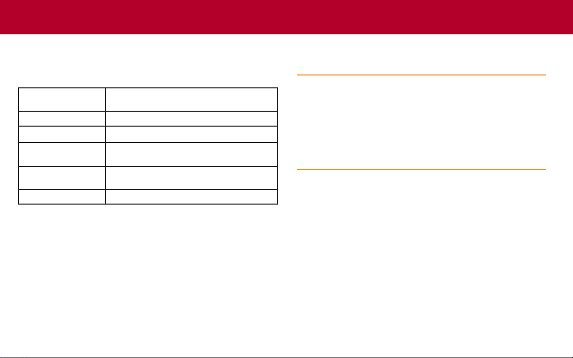
Power and environmental specications
For indoor use only.
Power supply
Maximum VA
Operating altitude
Operating
temperature
Storage temperature
Pollution category
100 V
to 240 V
RMS
(autosensing)
, 50 Hz to 60 Hz
RMS
220 VA
Maximum 2000 m (6562 ft) above sea level
0 °C to 50 °C, 70% relative humidity up to 35 °C
Derate 3% relative humidity/°C, 35 °C to 50 °C
–25 °C to +65 °C, 5% to 90% relative humidity
non-condensing
2
Carefully consider and congure the appropriate
output‑o state, source levels, and compliance levels
before connecting the instrument to a device that can
deliver energy. Failure to consider the output‑o state,
source levels, and compliance levels may result in
damage to the instrument or to the device under test.
Page 5

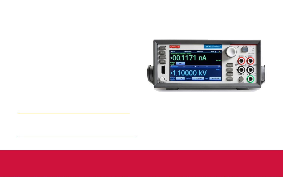
Introduction
Thank you for choosing a Keithley Instruments product.
The Model 2470 High Voltage SourceMeter
a precise, low-noise instrument that combines a stable DC
power supply with a repeatable, high-impedance multimeter.
The design of this instrument features intuitive set up and
control, enhanced signal quality and range, and better
resistivity and resistance capabilities than similar products on
the market.
®
instrument is
Complete documentation for the 2470 instrument is available
for download on the Keithley web page at tek.com/keithley.
The 2470 documentation includes:
• Quick Start Guide: This document. It provides unpacking
instructions, describes basic connections, and reviews
basic operation information.
• User’s Manual: Provides an overview of front-panel
instrument operation and detailed applications that show
you how to use the front panel, SCPI code, and TSP code
to perform typical source and measurement tasks.
• Reference Manual: Provides comprehensive information
about the instrument’s features, operation, optimization,
maintenance, troubleshooting, and programming
commands.
• Information on accessories.
Introduction
Page 6

Software for the 2470 is also available for download from the
Keithley web page at tek.com/keithley. You can search for
the specic software you need. Available software includes:
• Test Script Builder: Simplies building test scripts
for instruments enabled for Keithley’s Test Script
Processor TSP
®
).
• KickStart Instrument Control Software: Allows you to
set up your instrument and run a test without using any
programming languages (free trial version).
• IVI-COM Driver: Works in any development environment
that supports COM programming, including Microsoft
®
Visual Basic, Microsoft Visual C++, and National
Instruments LabVIEW
™
.
• Keithley I/O layer: Manages communications between
Keithley instrument drivers and software applications and
the instrument.
Page 7
Unpack and inspect the instrument
CAUTION
To unpack and inspect the instrument:
1. Inspect the box for damage.
2. Open the top of the box.
3. Remove the documentation and accessories.
4. Remove optional accessories (such as rack‑mount
hardware).
5. Remove the packaging insert.
6. Carefully lift the instrument out of the box.
7. Inspect the instrument for any obvious signs of physical
damage. Report any damage to the shipping agent
immediately.
Do not use the front bezel to lift the 2470. Using the front
bezel can cause damage to the instrument.
Unpack
Page 8

You receive the 2470 with the following accessories:
1 Model 8608 High Performance Test Leads
2 Power line cord
3 Model 2470‑903‑01 Quick Start Guide (this document)
4 Model CS‑1616‑3 Safety Interlock Mating Connector
5 Crossover cable for TSP‑Link or ethernet
6 USB‑B‑1 USB Cable, Type A to Type B (1 m)
7 Safety Precautions
Refer to the packing list for additional items that might have
shipped with your instrument.
Page 9

Connect the instrument
Important test system safety information
This product is sold as a stand-alone instrument that may
become part of a system that could contain hazardous
voltages and energy sources. It is the responsibility of the
test system designer, integrator, installer, maintenance
personnel, and service personnel to make sure the system is
safe during use and is operating properly.
You must also realize that in many test systems a single
fault, such as a software error, may output hazardous signal
levels even when the system indicates that there is no
hazard present.
It is important that you consider the following factors in your
system design and use:
• The international safety standard IEC 61010-1 denes
voltages as hazardous if they exceed 30 V
42.4 V
Keithley Instruments products are only rated for dry
locations.
• Read and comply with the specications of all instruments
in the system. The overall allowed signal levels may be
constrained by the lowest rated instrument in the system.
For example, if you are using a 500 V power supply with a
300 VDC rated switch, the maximum allowed voltage in the
system is 300 VDC.
, or 60 VDC for equipment rated for dry locations.
PEAK
RMS
and
• Cover the device under test (DUT) to protect the operator
from ying debris in the event of a system or DUT failure.
• Make sure any test xture connected to the system
protects the operator from contact with hazardous voltages,
hot surfaces, and sharp objects. Use shields, barriers,
insulation, and safety interlocks to accomplish this.
• Double-insulate all electrical connections that an operator
can touch. Double insulation ensures the operator is
still protected even if one insulation layer fails. Refer to
IEC 61010-1 for specic requirements.
• Make sure all connections are behind a locked cabinet door
or other barrier. This protects the system operator from
accidentally removing a connection by hand and exposing
hazardous voltages. Use high-reliability fail-safe interlock
switches to disconnect power sources when a test xture
cover is opened.
• Where possible, use automatic handlers so that operators
are not required to access the DUT or other potentially
hazardous areas.
• Provide training to all users of the system so that they
understand all potential hazards and know how to protect
themselves from injury.
• In many systems, during power up, the outputs may be in
an unknown state until they are properly initialized. Make
sure the design can tolerate this situation without causing
operator injury or hardware damage.
Connect
Page 10

NOTE
To keep users safe, always read and follow all safety warnings
WARNING
provided with each of the instruments in your system.
Install the instrument
You can use the 2470 on a bench or in a rack. See the
instructions that came with your rack-mount kit if you are
installing the 2470 in a rack.
To prevent damaging heat build-up and ensure specied
performance, make sure there is adequate ventilation and air
ow around the instrument to ensure proper cooling. Do not
cover the ventilation holes on the top, sides, or bottom of the
instrument.
Position the instrument so that it is easy to reach any
disconnecting devices, such as the power cord and the
power switch.
Wiring the interlock
The 2470 is provided with an interlock circuit that must
be positively activated in order for the high-voltage
output to be enabled. The interlock helps facilitate safe
operation of the equipment in a test system. Bypassing
the interlock could expose the operator to hazardous
voltages that could result in personal injury or death.
To perform high-voltage measurements, the 2470 interlock
must be connected to an interlock switch in the testing
environment. When properly connected, the safety interlock
of the 2470 places the outputs of the instrument in a safe
state. When the safety interlock signal is asserted, all voltage
ranges of the instrument are available. The green front-panel
INTERLOCK indicator is illuminated.
When the safety interlock signal is not asserted, the
high-voltage ranges are disabled, limiting the nominal output
to ±42 V. The front-panel INTERLOCK indicator is not
illuminated.
Page 11

You can only use the high-voltage outputs when the interlock
is asserted. If you try to assign a high-voltage output and
turn the source on when the interlock is not asserted, you
see event code 5074, “Output voltage limited by interlock.”
Note that the SOURCE swipe screen displays the value that
was selected for the voltage source, but the source value is
limited to ±42 V.
An interlock circuit is provided on the rear panel of the
instrument, as shown in the following gure. This circuit must
be closed to enable the 2470 to produce voltages greater
than ±42 V.
The interlock is intended for use through a normally open
switch, which may be installed on the lid of a test xture, on
the enclosure of a semiconductor prober or device handler,
or on the door or doors of a test equipment rack. The circuit
opens when an access door is opened and closes when the
door is closed.
When the interlock is asserted, any measurement terminals,
including the LO terminals, should be considered hazardous
voltages, even if they are programmed to a non-hazardous
voltage or current.
WARNING
Potentially hazardous voltages of up to approximately
1350 V may be present at any measurement terminals
when the interlock circuit is closed. To prevent electrical
shock, do not expose these lines.
Connect
Page 12

You can use the Keithley Instruments connector CS-1616-3,
NOTE
supplied with the 2470, to make the interlock connection
to the rear panel. You must supply connection wire. The
recommended wire is:
• 20 AWG to 26 AWG copper alloy
• 7 to 19 bare and tinned strands
• 0.14 mm
• Flexible vinyl, semi-exible vinyl, polyethylene, x-linked
polyethylene, or PTFE
To ensure proper interlock operation, the external interlock
switch and connection wires must be less than 10 Ω when
the switch is closed.
2
to 0.50 mm
2
The interlock pin locations and connections are shown in the
following gure. The pins are:
• Pin 3: Earth and chassis ground
• Pin 2: Interlock
• Pin 1: +6 V DC out (current limited)
For the examples shown in this quick start guide, you do not
need to use an interlock. The 2470 works on all current ranges
and up to ±42 volts without asserting the interlock.
Page 13

Power on the instrument
The 2470 operates from a line voltage of 100 V to 240 V at
a frequency of 50 Hz or 60 Hz. The instrument senses the
line voltage automatically. Before connecting line power,
make sure the operating voltage in your area is compatible.
WARNING
The power cord supplied with the 2470 contains a
separate protective earth (safety ground) wire for use
with grounded outlets. When proper connections are
made, the instrument chassis is connected to power-line
ground through the ground wire in the power cord.
In addition, a redundant protective earth connection
is provided through a screw on the rear panel. This
terminal should be connected to a known protective
earth. In the event of a failure, not using a properly
grounded protective earth and grounded outlet may
result in personal injury or death due to electric shock.
Do not replace detachable mains supply cords with
inadequately rated cords. Failure to use properly rated
cords may result in personal injury or death due to
electric shock.
To connect line power:
1. Make sure the front-panel power switch is in the o (O)
position.
2. Connect the socket of the supplied power cord to the
power module on the rear panel.
3. Connect the plug of the power cord to a grounded AC
outlet.
Connect
Page 14
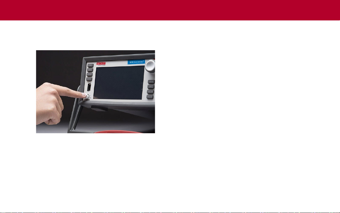
4. Turn on the instrument by pressing the front panel
POWER switch to the on (|) position. The instrument
starts.
Overview of the front-panel options
The front panel of the 2470 allows you to set up most
instrument functions and features and perform sourcing and
measuring operations. The front panel includes:
• A touchscreen display that allows you to access
instrument settings and measurement readings.
• Keys that select menu options and start measurement
operations.
• A navigation control that can be used to select screen
options.
• An Output On/O switch that turns the source output on
or o.
• Banana jack connections for FORCE HI and LO, SENSE
HI and LO, and chassis ground.
• A Terminals switch that determines if the instrument
uses the front or rear panel connections for sourcing and
measuring.
Page 15

Touchscreen display overview
You can use the touchscreen display to set up the instrument
and tests. You use the keys and touch capabilities to make
selections.
To use the touchscreen, select options with your nger. You
can also use the navigation control to highlight an item, and
then press the control to select it.
The following text describes some of the most commonly
used screens. For more detail and descriptions of all the
screens, see the Model 2470 Reference Manual. For detail
about an option, select it and press the HELP key to display
a brief description of the option.
Home screen overview
The Home screen is the rst screen that opens when the
instrument is powered on. You can always return to the
Home screen by pressing the HOME key.
The top row on the Home screen displays the status and
event indicators. You can select these options to open dialog
boxes that provide additional information about the status or
event.
The measure section of the Home screen displays the
present measurement. It also displays the measure function
and allows you to select a measure range.
Connect
Page 16

The bottom half of the touchscreen display contains multiple
screens that you can swipe to access additional information
and settings:
• SOURCE swipe screen: Displays the source
settings. When the output is on, this displays either
the programmed source value or the actual source,
depending on the setting of source readback. On the
source swipe screen, you can set the source range,
source value, and source limit.
• SETTINGS swipe screen: Allows you to turn features on
and o, such as the measurement lter, math functions,
relative oset, and NPLCs.
• GRAPH swipe screen: Shows a graph of the readings in
the presently selected buer. Touch the graph icon on the
right side of the graph swipe header to open a full-screen
graph view.
• STATISTICS swipe screen: Contains statistics based on
the readings in the active buer.
• USER swipe screen: Displays information that you can
dene through a remote interface.
An example of the SETTINGS swipe screen is shown below.
In the SETTINGS swipe screen shown here, the Auto Zero
feature is turned on. The other settings are turned o.
Page 17

In the GRAPH swipe screen shown here, you can view the
measurements as they occur. To see a full screen graph,
touch the graph icon on the right side of the swipe screen
header bar to go to the Graph screen. In the full-screen
graph, you can also change the data and scale of the
information that is displayed on the graph.
ENTER and EXIT keys
The ENTER key selects a highlighted option. In most cases,
it opens a menu or dialog box that allows you to make
settings for that option.
The EXIT key returns to the previous menu or closes a
dialog box. For example, if you are in the MENU screen,
press EXIT to return to the Home screen.
TRIGGER key
The action of the TRIGGER key depends on the trigger
method that is selected:
• If you set the instrument to continuously trigger, this
displays a dialog box that allows you to select another
measurement method.
• If you set the instrument to manually trigger, pressing
the TRIGGER key causes the instrument to make a
measurement.
• If you dened a trigger model, pressing the TRIGGER
key initiates the trigger model.
To change the trigger method, hold the TRIGGER key for
three seconds to display the methods you can choose.
Connect
Page 18

Menu screen overview
When you press the MENU key on the front panel, the Menu
screen is displayed.
From this screen, you can select source, measure, graphing,
trigger, scripting, and system setup menus. These menus
allow you to choose options to set up your instrument to
meet the needs of your applications.
An example of the options that are available when you select
the Settings option under Measure is shown below.
Page 19

Quick Setup options
CAUTION
When you press QUICKSET, the BASIC SOURCE/
MEASURE SETTINGS screen is displayed. From this menu,
you can:
• Choose the source and measure functions.
• Use the Performance slider to select the best balance
between measurement resolution and measurement
speed.
• Choose from a selection of Quick Setups that
automatically make the settings required for that setup,
turn the output on, and begin making measurements.
When you select a Quick Setup, the instrument turns
the output on. Carefully consider and congure the
appropriate output-o state, source, and limits before
connecting the 2470 to a device that can deliver energy,
such as other voltage sources, batteries, capacitors, or
solar cells. Congure the settings that are recommended
for the instrument before making connections to the
device. Failure to consider the output-o state, source,
and limits may result in damage to the instrument or to
the device under test (DUT).
Connect
Page 20

Help
FUNCTION
You can display help screens for the menu items and
buttons. The help screens give a brief description of
the option that the menu or button sets. To display the
description, highlight the menu item or button and press the
HELP key. The graphic below shows an example of the help
when you are on the System Events tab of the event log.
The FUNCTION key opens the FUNCTION selection dialog
box, which allows you to select the source and measure
functions.
The instrument saves many of the settings with the source
or measure function that was active when you set them. For
example, if you set the measure function to current and you
set a value for NPLCs, the instrument saves the NPLC value
for that measure function. When you change the measure
function to voltage, the NPLC value changes to the value
that was last set for the voltage measure function.
Page 21

Connections for testing
CAUTION
The following gure shows the physical connections for the
front panel. Note that you must use either the front terminals
or rear terminals — you cannot mix connections. The rear
terminal connections are triaxial. The front panel connections
are safety banana jacks.
The example in this guide shows you how to make
connections to the front panel and short the connections.
If you use the terminals on the rear panel for
connections, you must use the purple low-noise Keithley
Model TRX-1100V-X Three-Slot Triaxial Cables. Using the
incorrect cables could result in damage to the triaxial
connectors on the instrument.
For this example, you can make the connections with the
insulated banana cables that are supplied with the 2470, the
Keithley Instruments Model 8608 High Performance Test
Leads.
Make sure the front panel power switch is in the o (O)
position.
1. Connect the red lead to the FORCE HI connection.
2. Connect the black lead to the FORCE LO connection.
Test
Page 22

Verify measurement operation
The following steps provide a quick way to verify that the
instrument is operating correctly.
To verify measurement operation:
1. Turn the instrument on.
2. On the front panel, press the HOME key.
3. Press the FUNCTION key.
4. Under Source Current and Measure, select Voltage.
5. Select Source (at the bottom of the Home screen). The
Current Source Value dialog box is displayed.
6. Enter 10 mA.
7. Short the FORCE HI and FORCE LO connections.
8. Press the OUTPUT ON/OFF switch to enable the output
and start making measurements.
9. When measurements are complete, press the
OUTPUT ON/OFF switch to disable the output.
The voltage measurements appear in the Measure Voltage
area of the Home screen.
To save the data to a USB ash drive:
1. Insert a USB ash drive into the front‑panel USB port.
2. Press the MENU key.
3. Under Measure, select Reading Buers.
4. Select defbuer1.
5. Select Save To USB.
6. Enter the le name.
7. Select OK (on the screen). A conrmation message is
displayed.
8. Select Yes .
The instrument saves the data to a .csv le on the ash
drive.
Page 23

To view the measurements on the front-panel graph:
1. Press the MENU key.
2. Under Views, select Graph.
You can swipe and use pinch and zoom to change the view
of data on the graph. You can also adjust the graph settings
using the options in the Data and Scale tabs.
Test
Page 24

FAQs
Where can I nd updated drivers or rmware?
For the latest drivers and additional support information, see
the Keithley Instruments support website.
To nd drivers that are available for your instrument:
1. Go to tek.com/product-support.
2. Enter 2470 and select GO.
My data looks odd or is wrong. What should I do?
Verify the connections from the instrument to the test xture.
Also check the connections from the DUT to the test xture
socket.
How do I change the command set?
In addition to the front panel, you can use a remote interface
to set up the instrument. You can choose one of the following
command sets:
• SCPI: An instrument-specic language built on the SCPI
standard.
• TSP: A programming language that you can use to send
individual commands or combine commands into scripts.
You cannot combine the command sets.
As delivered from Keithley Instruments, the 2470 is set to
work with the SCPI command set.
To set the command set using the front panel:
1. Press the MENU key.
2. Under System, select Settings.
3. Select the button next to Command Set.
4. Select the command set.
5. Select OK to reboot the instrument.
Page 25

Why did my settings change?
Next steps
The instrument saves many of the commands with the
source or measure function that was active when you set
them. For example, assume you have the measure function
set to current and set a value for NPLCs. When you change
the measure function to voltage, the NPLC value changes to
the value that was last set for the voltage measure function.
When you return to the current measure function, NPLC
value returns to the value you set previously.
For more information, refer to the Keithley Instruments
website, tek.com/keithley, for support and additional
information about the instrument, including the following
documents:
• Model 2470 User Manual: Contains basic information
about the instrument, plus application-based examples
that help familiarize you with the instrument.
• Model 2470 Reference Manual: Provides detailed
information about all features of the instrument, including
descriptions of SCPI and TSP commands.
FAQs and next steps
Page 26

Contact information:
Australia* 1 800 709 465
Austria 00800 2255 4835
Balkans, Israel, South Africa, and other
ISE countries +41 52 675 3777
Belgium* 00800 2255 4835
Brazil +55 (11) 3759 7627
Canada 1 800 833 9200
Central East Europe / Baltics
+41 52 675 3777
Central Europe / Greece +41 52 675 3777
Denmark +45 80 88 1401
Finland +41 52 675 3777
France* 00800 2255 4835
Germany* 00800 2255 4835
Hong Kong 400 820 5835
India 000 800 650 1835
Indonesia 007 803 601 5249
Italy 00800 2255 4835
Japan 81 (3) 6714 3010
Luxembourg +41 52 675 3777
Malaysia 1 800 22 55835
Mexico, Central/South America, and
Caribbean 52 (55) 56 04 50 90
Middle East, Asia, and North Africa
+41 52 675 3777
The Netherlands* 00800 2255 4835
New Zealand 0800 800 238
Norway 800 16098
People’s Republic of China 400 820 5835
Philippines 1 800 1601 0077
Poland +41 52 675 3777
Portugal 80 08 12370
Republic of Korea +82 2 565 1455
Russia / CIS +7 (495) 6647564
Singapore 800 6011 473
South Africa +41 52 675 3777
Spain* 00800 2255 4835
Sweden* 00800 2255 4835
Switzerland* 00800 2255 4835
Taiwan 886 (2) 2656 6688
Thailand 1 800 011 931
United Kingdom / Ireland* 00800 2255 4835
USA 1 800 833 9200
Vietnam 12060128
* European toll-free number. If not
accessible, call: +41 52 675 3777
Find more valuable resources at TEK.COM
Copyright © 2019, Tektronix. All rights reserved.
Tektronix products are covered by U.S. and
foreign patents, issued and pending. Information
in this publication supersedes that in all previously
published material. Specfication and price change
privileges reserved. TEKTRONIX and TEK are
registered trademarks of Tektronix, Inc. All other
trade names referenced are the service marks,
trademarks, or registered trademarks of their
respective companies.
2470-903-01 Rev. A / March 2019
*P2470-903-01A*
 Loading...