

Page 1

www.keithley.com
Series 2200
Multichannel Programmable DC Power Supplies
User Manual
2220S-900-01 Rev. A / June 2012
ECNEDIFNOC FO ERUSAEM RETAERG A
Page 2

Page 3

Multichannel Programmable DC Power Supplies
Series 2200
User Manual
© 2012, Keithley Instruments, Inc.
Cleveland, Ohio, U.S.A.
All rights reserved.
Any unauthorized reproduction, photocopy, or use the information herein, in whole or in part,
without the prior written approval of Keithley Instruments, Inc. is strictly prohibited.
All Keithley Instruments product names are trademarks or registered trademarks of Keithley
Instruments, Inc. Other brand names are trademarks or registered trademarks of their respective
holders.
Document number: 2220S-900-01 Rev. A / June 2012
Page 4

Page 5

Safety Precautions
The following safety precautions should be observed before using this product and any associated instrumentation. Although
some instruments and accessories would norma lly be used with nonhazardous voltages, there are situations where hazardous
conditions may be present.
This product is intended for use by qualified personnel who recognize shock hazards and are familiar with the safety precautions
required to avoid possible injury. Read and follow all installation, operation, and maintenance information carefully before using
the product. Refer to the user documentation for complete product specifications.
If the product is used in a manner not specified, the protection provided by the product warranty may be impaired.
The types of product users are:
Responsible body is the individual or group responsible for the use and maintenance of equipment, for ensuring that the
equipment is operated within its specifications and operating limits, and for ensuring that operators are adequately trained.
Operators use the product for its intended function. They must be trained in electrical safety procedures and proper use of the
instrument. They must be protected from electric shock and contact with hazardous live circuits.
Maintenance personnel perform routine procedures on the product to keep it operating properly, for example, setting the line
voltage or replacing consumable materials. Maintenance procedures are described in the user documentation. The procedures
explicitly state if the operator may perform them. Otherwise, they should be performed only by service personnel.
Service personnel are trained to work on live circuits, perform safe installations, and repair products. Only properly trained
service personnel may perform installation and service procedures.
Keithley Instruments products are designed for use with electrical signals that are rated Measurement Category I and
Measurement Category II, as described in the International Electrotechnical Commission (IEC) Standard IEC 60664. Most
measurement, control, and data I/O signals are Measurement Category I and must not be directly connected to mains voltage or
to voltage sources with high transient overvoltages. Measurement Category II connections require protection for high transient
overvoltages often associated with local AC mains connections. Assume all measurement, control, and data I/O connections are
for connection to Category I sources unless otherwise marked or described in the user documentation.
Exercise extreme caution when a shock hazard is present. Lethal voltage may be present on cable connector jacks or test
fixtures. The American National Standards Institute (ANSI) states that a shock hazard exists when voltage levels greater than
30 V RMS, 42.4 V peak, or 60 VDC are present. A good safety practice is to expect that hazardous voltage is present in any
unknown circuit before measuring.
Operators of this product must be protected from electric shock at all times. The responsible body must ensure that operators
are prevented access and/or insulated from every connection point. In some cases, connections must be exposed to potential
human contact. Product operators in these circumstances must be trained to protect themselves from the risk of electric shock. If
the circuit is capable of operating at or above 1000 V, no conductive part of the circuit may be exposed.
Do not connect switching cards directly to unlimited power circuits. They are intended to be used with impedance-limited
sources. NEVER connect switching cards directly to AC mains. When connecting sources to switching cards, install protective
devices to limit fault current and voltage to the card.
Before operating an instrument, ensure that the line cord is connected to a properly-grounded power receptacle. Inspect the
connecting cables, test leads, and jumpers for possible wear, cracks, or breaks before each use.
When installing equipment where access to the main power cord is restricted, such as rack mounting, a separate main input
power disconnect device must be provided in close proximity to the equipment and within easy reach of the operator.
For maximum safety, do not touch the product, test cables, or any other instruments while power is applied to the circuit under
test. ALWAYS remove power from the entire test system and discharge any capacitors before: connecting or disconnecting
cables or jumpers, installing or removing switching cards, or making internal changes, such as installing or removing jumpers.
Do not touch any object that could provide a current path to the common side of the circuit under test or power line (earth)
ground. Always make measurements with dry hands while standing on a dry, insulated surface capable of withstanding the
voltage being measured.
The instrument and accessories must be used in accordance with its specifications and operating instructions, or the safety of
the equipment may be impaired.
11/07
Page 6

Do not exceed the maximum signal levels of the instruments and accessories, as defined in the specifications and operating
information, and as shown on the instrument or test fixture panels, or switching card.
When fuses are used in a product, replace with the same type and rating for continued protection against fire hazard.
Chassis connections must only be used as shield connections for measuring circuits, NOT as safety earth ground connections.
If you are using a test fixture, keep the lid closed while power is applied to the device under test. Safe operation requires the use
of a lid interlock.
If a
screw is present, connect it to safety earth ground using the wire recommended in the user documentation.
The symbol on an instrument means caution, risk of danger. The user should refer to the operating instructions located in
the user documentation in all cases where the symbol is marked on the instrument.
The
symbol on an instrument means caution, risk of electric shock. Use standard safety precautions to avoid personal
contact with these voltages.
The
The
If this
symbol on an instrument shows that the surface may be hot. Avoid personal contact to prevent burns.
symbol indicates a connection terminal to the equipment frame.
symbol is on a product, it indicates that mercury is present in the display lamp. Please note that the lamp must be
properly disposed of according to federal, state, and local laws.
The WARNING heading in the user documentation explains dangers that might result in personal injury or death. Always read
the associated information very carefully before performing the indicated procedure.
The CAUTION heading in the user documentation explains h az ards that coul d dama ge the instr ume nt. Such dam age may
invalidate the warranty.
Instrumentation and accessories shall not be connected to humans.
Before performing any maintenance, disconnect the line cord and all test cables.
To maintain protection from electric shock and fire, replacement components in mains circuits — including the power
transformer, test leads, and input jacks — must be purchased from Keithley Instruments. Standard fuses with applicable national
safety approvals may be used if the rating and type are the same. Other components that are not safety-related may be
purchased from other suppliers as long as they are equivalent to the original component (note that selected parts should be
purchased only through Keithley Instruments to maintain accuracy and functionality of the product). If you are unsure about the
applicability of a replacement component, call a Keithley Instruments office for information.
To clean an instrument, use a damp cloth or mild, water-based cleaner. Clean the exterior of the instrument only. Do not apply
cleaner directly to the instrument or allow liquids to enter or spill on the instrument. Products that consist of a circuit board with
no case or chassis (e.g., a data acquisition board for installation into a computer) should never require cleaning if handled
according to instructions. If the board becomes contaminated and operation is affected, the board should be returned to the
factory for proper cleanin g/s er v icing.
11/07
Page 7

Table of Contents
Preface................................................................................................................................. ii
Welcome.......................................................................................................................... ii
Products .. . .. .. .. .. .. .. .. .. .. .. .. .. .. .. .. .. .. . . .. .. .. .. .. . . .. .. .. .. .. .. .. .. . . .. .. .. .. .. . . .. .. .. .. .. .. .. .. . . .. .. .. .. .. .. .. .. . . .. ... ii
Extended Warranty. .. .. . . .. .. .. .. .. . . .. .. .. .. .. . . .. .. .. .. .. . . .. .. .. .. .. . . .. .. . . .. .. .. .. .. . . .. .. .. .. .. . . .. .. .. .. .. . . .. .. .. .. .. . . .. ii
Contact Inf
CD-ROM Contents ............................................................................................................... iii
Key Features ..................................................................................................................... iii
Getting St
Standard Accessories.. . .. .. .. .. .. .. .. . . .. .. .. .. .. .. .. .. .. .. .. .. .. .. .. .. .. .. .. .. . . .. .. .. .. .. .. .. .. .. .. .. .. .. .. .. .. .. .. .. .. .. .. .. . 1
Optional Accessories .. . .. .. .. .. .. .. .. .. .. .. .. .. .. . . .. .. .. .. .. . . .. .. . . .. .. .. .. .. . . .. .. . . .. .. .. .. .. . . .. .. . . .. .. .. .. .. . . .. .. . . .. .. . 1
Available
Specifications..................................................................................................................... 3
Operating Requirements. . . . .. .. .. .. .. .. .. .. .. .. .. .. .. .. .. .. .. .. .. .. .. .. .. . . .. .. .. .. .. .. .. .. .. .. .. .. .. .. .. .. .. .. .. .. . . .. .. .. .. .. . 4
Front-pa
Rear-panel Features .. . . . .. .. .. .. .. .. .. .. . . .. .. .. .. .. .. .. .. .. .. .. .. .. .. .. .. .. .. .. .. . . .. .. .. .. .. .. .. .. .. .. .. .. .. .. .. .. .. .. .. .. . . .. 9
Front-panel Operation. . . . .. .. .. .. .. . . .. .. .. .. .. . . .. .. .. .. .. . . .. .. .. .. .. . . .. .. . . .. .. .. .. .. . . .. .. .. .. .. . . .. .. .. .. .. . . .. .. .. .. .. . . . 11
Install
Cleaning .. . .. .. .. .. .. .. .. .. . . .. .. .. .. .. . . .. .. .. .. .. . . .. .. .. .. .. . . .. .. .. .. .. . . .. .. .. .. .. . . .. .. .. .. .. . . .. .. .. .. .. . . .. .. .. .. .. . . .. .. 15
Operating Basics ..................................................................................................................... 16
Basic S
Menu Operations................................................................................................................ 17
User Settings ....................................................................................................................19
System
Configure The Instrument for Your Application . . . . .. .. . . .. .. .. .. .. . . .. .. .. .. .. . . .. .. .. .. .. . . .. .. .. .. .. . . .. .. .. .. .. . . .. .. .. .. .. 22
Connect to a Device Under Test . .. . . .. .. .. .. .. .. .. .. .. .. .. .. .. .. .. .. .. .. .. .. . . .. .. .. .. .. .. .. .. .. .. .. .. .. .. .. .. .. .. .. .. . . .. .. .. . 22
Index
ormation .............................................................................................................. ii
arted......................................................................................................................... 1
Services................................................................................................................ 2
nel Features............................................................................................................. 5
ing theSystem............................................................................................................ 12
ettings................................................................................................................... 16
Information ............................................................................................................. 21
Table of Content
s
Series 2200 Multi-Channel Programmable DC Power Supplies User Manual i
Page 8

Preface
Preface
Welcome
Thank you for using a Keithley Instruments product. The Series 2200 Multichannel Programmable DC Power Supplies are
flexible DC sources designed to power a wide range of applications. The model 2230-30-1 offers three power channels and
the model 2220-30-1 provides two channels. The output channels on both models are independent and isolated, allowing
you to power circuits with different references or polarities. Each channel can be enabled or disabled as your application
requires. All outputs feature remote sense capability which can be used to reduce the effect of lead resistance, delivering
0.03% basic voltage accuracy even when using long leads. Basic current accuracy is 0.1% for all channels and linear
regulation delivers low noise – less than 3 mVp-p. Flexible display modes make it easy to use the two 30 V outputs in
combination, and the USB interface makes it easy to build PC-based systems without converters or special cables.
These compact power supplies cover a wide range of applications without covering a lot of bench space. Versions of these
power supplies are available for use at 100 VAC nominal line voltage which is common in Japan. These versions are
indicated by the "J" suffix.
Products
This manual contains information about the following products:
Model Descript
2220-30-1
2220J-30-1
2230-30-1
2230J-30-1
Extended Warranty
Additional years of warranty coverage are available on many products. These valuable contracts protect you from
unbudgeted service expenses and provide additional years of protection at a fraction of the price of a repair. Extended
warranties are available on new and existing products. Contact your local Keithley Instruments representative for details.
Contact Information
If you have any questions after reviewing this information, please use the following sources:
1. Keithley Instruments website (http://www.keithley.com)
2. Keithley web forum (http://forum.keithley.com)
3. Call Keithley Instruments corporate headquarters (toll-free inside the U.S . and Canada only) at 1-888-KEITHLEY
(1-888-534-8453), or from outside the U.S. at +1-440-248-0400. For worldwide contact numbers, visit the Keithley
struments website (http://www.keithley.com).
In
ion
Dual Cha
Dual Ch
Triple
Tripl
nnel Programmable DC Power Supply
annel Programmable DC Power Supply for Japan
Channel Programmable DC Power Supply
e Channel Programmable DC P ower Supply for Japan
ii Series 2200 Multi-Channel Programmable DC Power Supplies User Manual
Page 9

CD-ROM Contents
A CD-ROM is shipped with each Series 2200 order. The Series 2200 Product Information CD-ROM contains:
User manual: Includes a description of connections, operation information, and maintenance information. Users looking
for basic operating information and an in-depth description of the way the instrument works (including troubleshooting
and optimization) should refer to this manual.
Specifications and performance verification manual: Includes instrument specifications and procedures to verify that
instrument accuracy is within the limits stated in the instrument’s one-year accuracy specifications.
Programmer’s manual: Includes instrument programming information. Programmers looking for command references
should refer to this manual.
PC Connectivity manual: Includes instructions for installing software, drivers, and files to use LabVIEW SignalExpress
Edition software to remotely acquire data and measurements from supported instruments.
Drivers and release notes: IVI Instrument Driver, driver for National Instruments LabVIEW™, and related release
notes; SignalExpress Step and related release notes.
Keithley I/O layer and release notes.
Security and declassification instructions: Includes information about how to sanitize and secure the instrument for
customers with security concerns.
Preface
For the latest drivers and additional support information, see the Keithley Instruments website (http://www.keithley.com).
Key F eatures
ies 2200 instruments offer:
The Ser
Two 30 V
6Vat5A
1-year
r regulation
Linea
0.03%
0.1% B
than3mV
Less
te sense to compensate for lead resistance
Remo
er-defined setup memories
30 us
Device port on rear-panel for PC connectivity and remote programming
USB
ks with National Instruments LabVIEW SignalExpress™ Tektronix Limited Edition Software which is available for
Wor
download at www.tektronix.com/downloads
at 1.5 A channels
, a third channel (2230 models only)
factory warranty extendable to 5 years
Basic voltage accuracy
asic current accuracy
ripple and noise
pp
Series 2200 Multi-Channel Programmable DC Power Supplies User Manual iii
Page 10

Preface
iv Series 2200 Multi-Channel Programmable DC Power Supplies User Manual
Page 11

Getting Started
Getting Start
ed
Standard Accessories
For the current list of standard and optional accessories, upgrades, and options available for your power supply, visit the
Keithley website, www.Keithley.com.
Table 1: Standard accessories
Accessory
Series 2200 Product Information CD-ROM. You can view a list of the contents of this CD. (See
page iii, CD-ROM Contents.)
Rear Panel Mating Connector with shorting clips for 2220-30-1 and 2230-30-1 CS-1655-15
Certificate of calibration
1
Power Cord
1
Models 2220J-30-1 and 2230J-30-1 come standard with a Japanese power cord. No other power cord options are available for these models.
One of the following:
North America (Option A0). The factory sets the 110V/220V selector switch
to 110 V.
Universal Euro (Option A1). The factory sets the 110V/220V selector switch
to 220 V.
United Kingdom (Option A2). The factory sets the 110V/220V selector switch
to 220 V.
Australia (Option A3). The factory sets the 110V/220V selector switch to 220 V.
Chile, Italy (Option A4). The factory sets the 110V/220V selector switch to 220 V.
Switzerland (O ption A5). T he factory sets the 110V/220V selector switch to
220 V.
Denmark (Option A7). The factory sets the 110V/220V selector switch to 220 V.
Israel (Option A8). The factory sets the 110V/220V selector switch to 220 V.
Argentina (Option A9). The factory sets the 110V/220V selector switch to 220 V.
China (Option A10). The factory sets the 110V/220V selector switch to 220 V.
India (Option A11). The factory sets the 110V/220V selector switch to 220 V.
Keithley part
number
2220S-950-01 Rev.
A / June 2012
—
Optional Accessories
For the current list of standard and optional accessories, upgrades, and options available for your power supply, visit the
Keithley website, www.Keithley.com.
Table 2: Optional accessories
Accessory
Fixed Mount Rack Kit 4299-7
Series 2200 Multichannel Rear Panel Mating Connector CS-1655-15
Series 2200 Multi-Channel Programmable DC Power Supplies User Manual 1
Keithley part
number
Page 12

Getting Started
Available Services
For the current list of available services and accessories, upgrades, and options for your instrument, visit the Keithley
website, www.keithley.com.
Table 3: Available services
Service Keithley part numbers
1-year factory warranty extended to 1 additional year from date of
shipment
1-year factory warranty extended to 3 years from date of shipment
1-year factory warranty extended to 5 years from date of shipment
3 calibrations within 3 years of service from date of shipment C/2220-30-1-3Y-STD
3 (ANSI-Z540-1 compliant) calibrations within 3 years of purchase from
date of shipment
3 calibrations within 5 years of service from date of shipment C/2220-30-1-5Y-STD
3 (ANSI-Z540-1 compliant) calibrations within 5 years of purchase from
date of shipment
1
Select the part number that contains your instrument model. For example, you would select 2220-30-1-EW for a model 2220 instrument.
1
2220-30-1-EW
2230-30-1-EW
2220J-30-1-EW
2230J-30-1-EW
2220-30-1-3Y-EW
2230-30-1-3Y-EW
2220J-30-1-3Y-EW
2230J-30-1-3Y-EW
2220-30-1-5Y-EW
2230-30-1-5Y-EW
2220J-30-1-5Y-EW
2230J-30-1-5Y-EW
C/2230-30-1-3Y-STD
C/2220J-30-1-3Y-STD
C/2230J-30-1-3Y-STD
C/2220-30-1-3Y-DATA
C/2230-30-1-3Y-DATA
C/2220J-30-1-3Y-DATA
C/2230J-30-1-3Y-DATA
C/2230-30-1-5Y-STD
C/2220J-30-1-5Y-STD
C/2230J-30-1-5Y-STD
C/2220-30-1-5Y-DATA
C/2230-30-1-5Y-DATA
C/2220J-30-1-5Y-DATA
C/2230J-30-1-5Y-DATA
2 Series 2200 Multi-Channel Programmable DC Power Supplies User Manual
Page 13

Specifications
For more specifications, refer to the Specifications and Performance Verification Technical Reference included on the
CD-ROM that was shipped with your instrument.
Table 4: Electrical ratings for the power connection, frequency 50/60 Hz
Model
2220-30-1
2220J-30-1
2230-30-1
2230J-30-1
Table 5: Environmental performance for all models
Parameter Description
Temperature
Humidity
Altitude
Getting Started
Line Selector
Switch Setting Voltage Range Fuse Rating Max Power
110 V / 220 V 110: 110/115/120
220: 220/230/240
110 V / 220 V
110 V / 220 V 110: 110/115/120
110 V / 220 V
Operating: +0 °C to +40 °C
Operating:
5% to 95% relative humidity (% RH) at up to 40 °C, non-condensing
Operating: 100% capability up to 2,000 meters
110: 100 V
220: 200 V
220: 220/230/240
110: 100 V
220: 200 V
For 110 V: 6.3 A TH, 250 V
For 220 V: 3.15 A TH, 250 V
For 110 V: 6.3 A TH, 250 V
For 220 V: 3.15 A TH, 250 V
For 110 V: 6.3 A TH, 250 V
For 220 V: 3.15 A TH, 250 V
For 110 V: 6.3 A TH, 250 V
For 220 V: 3.15 A TH, 250 V
350 VA
350 VA
450 VA
450 VA
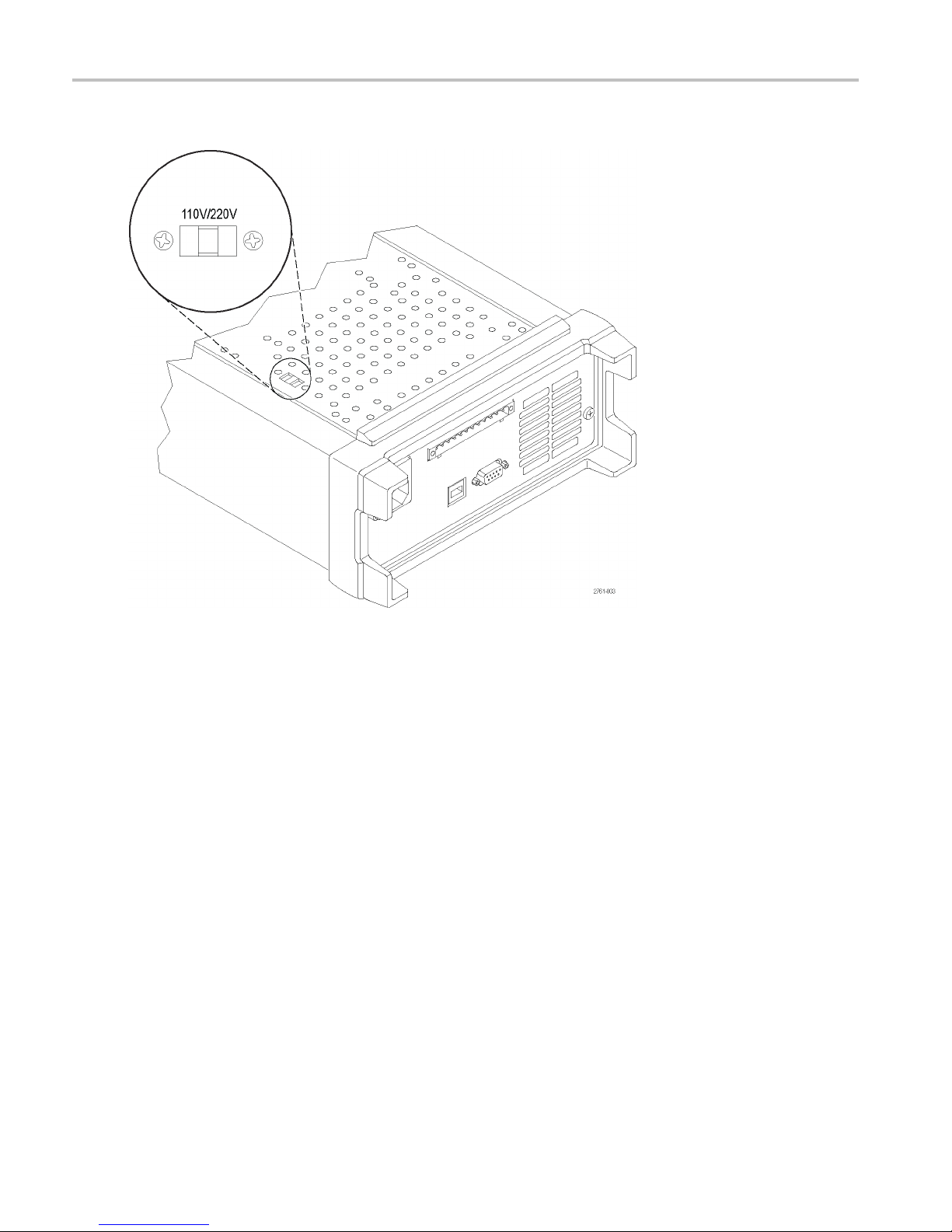
Nominal Voltage Ratings
There are two ranges for all models, selectable by the line-voltage selector switch. Check the voltage select switch on the
om of the power supply before turning it on:
bott
V setting, 110 / 115 / 120 VAC
110
V setting, 220 / 230 / 240 VAC
220
ctuations must not exceed 10% of the nominal rated voltage.
Flu
Float Voltage Rating
Float voltage rating: Any output can be floated up to 240 V (DC + pk AC with AC limited to a maximum of 3 V pk-pk and
maximum of 60 Hz) relative to any other output terminal. The remote sense terminals should remain within 1 V of their
respective outputs to avoid possible damage.
Series 2200 Multi-Channel Programmable DC Power Supplies User Manual 3
Page 14

Getting Started
Operating Requirements
1. Place the instrument on a bench or similar surface with the bottom of the instrument closest to the surface.
WARNING. Do not stand the instrument on its rear-panel. This position is unstable and the instrument might tip over and be
damaged or fall on someone and cause injury. To avoid damage to the instrument or bodily injury, only place the instrument
so that the bottom of the instrument is laid flat on a stable surface.
2. Before operating, ensure that the ambient temperature is between +0 °C and +40 °C (+32 °F to +104 °F).
WARNING. To ensure proper cooling, keep the front, sides, and rear of the instrument clear of obstructions.
WARNING. Observe all safety precautions listed in this manual before using this product and any associated instruments.
Although some instruments and accessories would be used with non-hazardous voltages, there are situations where
hazardous conditions may be present. This product is intended for use by qualified personnel who recognize shock hazards
and are familiar with the safety precautions required to avoid possible injury. Read and follow all installation, operation, and
maintenance information carefully before using the product. Refer to this manual for complete product specifications. Before
performing any maintenance, disconnect the line cord and all test cables. Operators of this instrument must be protected
from electric shock at all times. The responsible body must ensure that operators are prevented access and/or insulated from
every connection point. In some cases, connections must be exposed to potential human contact. Product operators in these
circumstances must be trained to protect themselves from the risk of electric shock. If the circuit is capable of operating at or
above 1000 volts, no conductive part of the circuit m ay be exposed.
WARNING. Use properly rated load wires. All load wires must be heavy enough not to overheat when carrying the maximum
short-circuit output current of the power supply. If there is more than one load, then any pair of load wires must be capable
of safely carrying the full-rated short-circuit output current of the power supply.
WARNING. Do not loosen any screw on this product, except those in the rear connector, which are intended to retain
attached external wires to the connector. There are no user serviceable components inside.
WARNING. To reduce risk of fire and shock, ensure the mains supply voltage fluctuations do not exceed 10% of the
operating voltage range.
4 Series 2200 Multi-Channel Programmable DC Power Supplies User Manual
Page 15
Front-panel Features
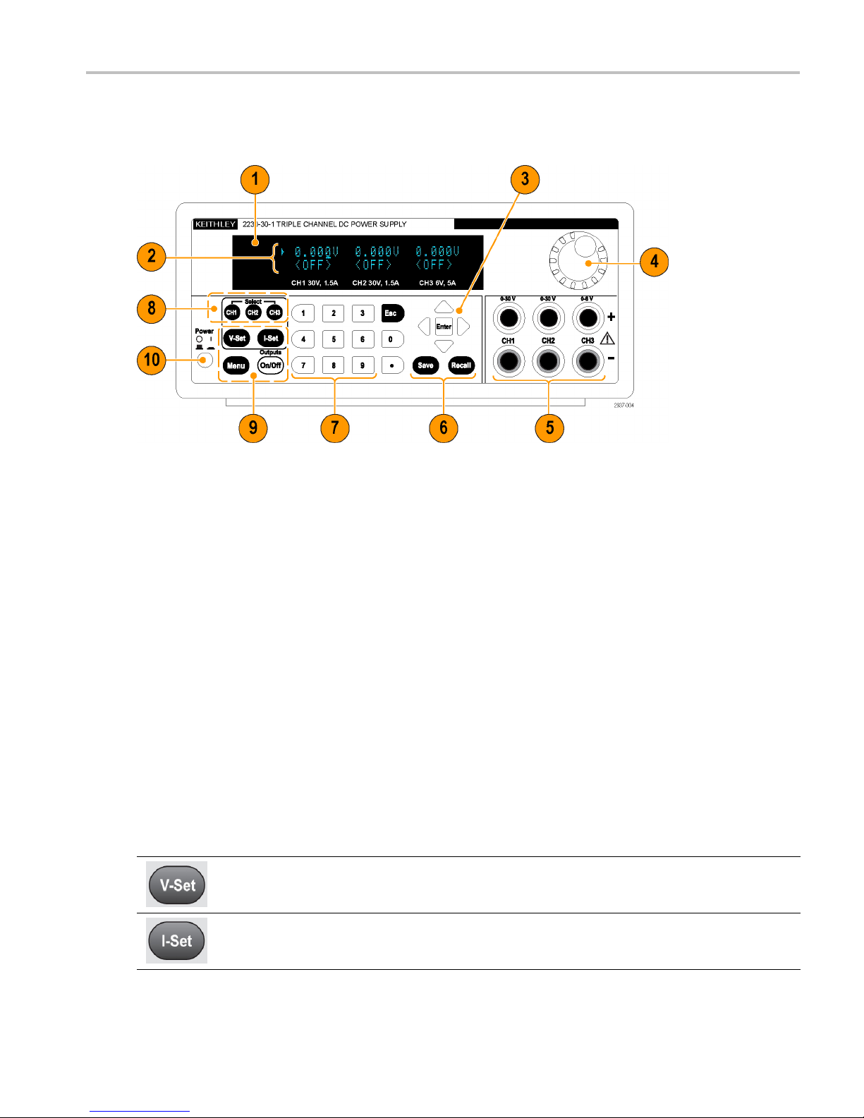
Controls and display elements are shown in the following illustrations and tables.
Figure 1: Front-panel of the model 2230-30-1, which has three output channels.
Getting Started
1. Display
2. Top row: Voltage readings or settings for each c hannel.
Bottom row: Current readings or settings for each channel.
3. Up, down, right, and left arrow keys and Enter button
4. Multipurpose knob. Rotate to increase or decrease digits or to select menu items
5. Output connectors
6. Save and Recall function buttons
7. Number keys (0 to 9 and Esc) for direct numeric entry
8. Channel select buttons
9. V-Set, I-Set, Menu (Local), and Output On/Off function buttons
10. Power button
Function button descriptions
Button Description
Sets the voltage limit
Sets the current limit
Series 2200 Multi-Channel Programmable DC Power Supplies User Manual 5
Page 16

Getting Started
Function button descriptions (cont.)
Button Description
Saves the present settings to a specified setup memory location (1 to 30). Select the memory location
with the multipurpose knob, the up or down arrow keys, or the numeric keypad. The power supply
saves the settings after you push Enter.
Recalls a saved setting from a specified setup memory location (1 to 30). Select the memory location
with the multipurpose knob, the up or down arrow keys, or the numeric keypad. The power supply
recalls the settings after you push Enter.
Used to access the settings menu. Navigate the settings menu with the up and down keys. Push
Enter to select the displayed menu item.
Selects the channel to be adjusted. The cursor indicates the currently selected channel.
Turns on or off all enabled output channels. The regulation mode, constant voltage (CV) or constant
current (CC), is shown on the display w hen the output is turned on.
Backs ou
one menu level.
t of the selected function. If the instrument's focus is in a menu, pushing Esc will back up
Menu descriptions
y
Primar
Menu
>Default Set Returns the instrument to the factory default setup values. This does not change the
>Enable
Channels
>Protection
Settings
>Track
H1/CH2
C
> Combine
CH1+CH2
ary
Second
Menu Description
setup memory.
Enables or disables one or more output channels.
>Max Volt
Set
tput
>Ou
Timers
ey Lock
>K
Sets the maximum output voltage value to which you can set on a specified output
nnel.
cha
er you select “On”, you can set a time period after which a specified output channel
Aft
will turn off.
When activated, this feature locks the front-panel controls and prompts for a password
to enable settings changes. This feature does not lock the power switch or the output
/off sw itch.
on
aintains a constant ratio between Channel 1 and Channel 2. The ratio is the ratio
M
that is present when tracking is turned on.
Series V1+V2: By wiring Channel 1 and Channel 2 in series, you can output up to
60 V. When this setting is activated the meter will read the combined voltage across
Channel 1 and Channel 2.
Parallel I1+I2: By wiring Channel 1 and Channel 2 in parallel, you can drive up to 3 A.
When this setting is activated the meter will read the combined current from Channel
1 and Channel 2.
6 Series 2200 Multi-Channel Programmable DC Power Supplies User Manual
Page 17

Menu descriptions (cont.)
Getting Started
Primary
Menu
>User
Settings
>System Info
Secondary
Menu Description
>Output
Recall
>Save Last Recalls the operating parameters of the power supply after power up. It does this by
>Key Beep
>Knob Lock Locks the multipurpose knob.
>Address
> Error Log Lists all errors that have occurred.
Firmware/SW version
>Cal Date Shows the date and time of the last calibration.
Sets the power output On/Off state after power up. “On” restores the state to that
which was in use before the power was last turned off. “Off” disables this function and
configures the output channel to power up in the off state.
NOTE. Wait 3 seconds after changing the settings to allow the settings to be completely
stored before powering off the instrument
saving the last s etting of operating parameters before you turn the instrument off and
then restoring the saved setting when you turn the instrument back on.
NOTE. Wait 3 seconds after changing the settings to allow the settings to be completely
stored before powering off the instrument.
Turns on or off a beeper sound when you push a button or press a key. “On” enables
the key sound. “Off” disables it.
Select a GPIB address for use with the Keithley GPIB to Series 2200 Multichannel Rear
Panel Mating Connector (CS-1655-15).
Shows the versions of firm ware installed on the instrument.
Channel status messages
Symbol Description
OFF The power supply output is off
CV Constant voltage mode
CC Constant current mode
Displayed error messages
Symbol Description
EEPROM Test Fail An EEPROM Error was detected during power-on self test. The instrument should be
returned to K e ithley for service.
User Data Lost
Channel Initialization
Failed
Calibration Data Lost A calibration data error was detected during power-on self test. Turn the instrum
Setup x Save Failure! Saving a setup to memory x failed. The instrument should be r eturned to K eithley for service.
A user data error was detected during power-on self test. Turn the instrument off and t
turn it back on to clear the error. If the error occurs repeatedly, the instrument should be
returned to K e ithley for service.
An output channel failure was detected during power-on self test. The instrument should
be returned to Keithley for service.
then turn it back on to clear the error. If the error occurs repeatedly, the instrument should
be returned to Keithley for service.
hen
ent off and
Series 2200 Multi-Channel Programmable DC Power Supplies User Manual 7
Page 18

Getting Started
Displayed error me ssages (cont.)
Symbol Description
Invalid Operation A Save operation may have been attempted while the instrument was in tracking, series, or
Over Temperature... An internal over-temperature has been detected and the outputs have been turned off. Check
parallel mode. A tracking, parallel, or series setup cannot be saved in setup memory.
A Recall operation may have been attempted while the instrument was in tracking, series, or
parallel mode. The recall function is disabled in these modes.
to make sure ambient temperature does not exceed the operating temperature specification
of the instrument, and insure the fan has sufficient clearance. Allow the instrument to cool
down and press any button to clear the error. If the message occurs repeatedly, return the
instrument to Keithley for service.
8 Series 2200 Multi-Channel Programmable DC Power Supplies User Manual
Page 19

Rear-panel Features
Figure 2: Rear-panel of the 2230-30-1.
Getting Started
1. Cooling vents
2. Factory test port
CAUTION
3. USB Device port
4. 110 V/220 V power connector
5. 15-pin connector. Includes remote sense and earth ground connections. For each output channel, there is an Output
6. Shorting clips (one per output channel). Use these for proper regulation when not using remote sense. The shorting clips
. Unauthorized use of the factory test port could damage this product.
Drive +, a Sen
The Output Dr
The Output Dr
The Output S
The Earth Gr
power cord.
come installed. They short the drive + to the sense + and the drive - to the sense - for each channel. To use remote
sense for o
se +, an Output Drive -, a Sense -, and an earth ground.
ive + terminals are equivalent to the front-panel output + connectors.
ive - terminals are equivalent to the front-panel output - connectors.
ense + and - terminals are used for remote sensing.
ound terminals are tied to each other, to the chassis of the instrument, and to the earth terminal on the
ne or more channels, remove the shorting clip for the corresponding channel(s).
Series 2200 Multi-Channel Programmable DC Power Supplies User Manual 9
Page 20
Getting Started
7. 110 V/220 V selector switch
10 Series 2200 Multi-Channel Programmable DC Power Supplies User Manual
Page 21

Front-panel Operation
Within a few seconds after powering on, the power supply shows the actual voltage for each channel on the top line of the
display and the actual current for each channel on the bottom line of the display.
You can enable or disable the output of the power supply from the front-panel by pushing the Output On/Off button. When
the output is off, the OFF message will appear on the display.
The display shows the present operating status of each channel with display messages. W hen a channel operates in constant
voltage mode, the CV indicator is displayed. When it operates in the constant current mode, the CC indicator is displayed.
NOTE. If the front-panel was locked with a password, enter the correct password after you push the function buttons (V-set,
I-set, Save, Recall,orMenu), then you can change the settings.
NOTE. To cancel a function operation (V-set, I-set, Save, Recall,orMenu), push the Esc button.
Initializing to the Default Setup
Getting Started
Use the d
1. Remove a
2. Turn on t
3. Push Men
4. Push En
5. Push th
The de
efault setup to get the power supply into a default initial state.
e down arrow button to select Yes. Push Enter to enable the default settings.
fault settings are:
tOn/Off= OFF
Outpu
= 1.000V for all channels
V-Set
= 0.1000A for all channels
I-Set
Lock = Off
Knob
olt Set = Off for all channels
Max V
ime Set = Off for all channels
Out T
put Recall = Off
Out
e Last = On
Sav
ll leads from the output connectors.
he power supply.
u. Default Set should appear on the display.
ter to bring up the default settings menu. No and Yes should appear on the display.
Beep = Off
Key
acking = Off
Tr
ries V1 + V2 = Off
Se
rallel I1 + I2 = Off
Pa
dress = 1
Ad
Series 2200 Multi-Channel Programmable DC Power Supplies User Manual 11
Page 22

Getting Started
Connect to an External Computer with USB
1. Load VISA on your computer. You can
2. Connect the instrument to the computer
download NI VISA from the National
Instruments website at www.NI.com.
with a USB cable. The computer will
then recognize the power supply as a
USB device. If National Instruments
SignalExpress is installed, the computer
will also give you the option of running
that program.
For more information on loading
and running SignalExpress, see the
Connectivity Installation Manual on the
Documentation Browser CD that was
shipped with your instrument. You can
also download a copy of this manual
from www.Keithley.com/manuals.
Installing the System
This section contains information on how to install your instrument. Before performing the procedures on the next several
pages to verify that the instrument is ready to use, do the following:
Unpack the instrument and check that you received all the items listed a s standard accessories.
Check that you also received any other accessories that you ordered with your instrument.
Check the Keithley website (www.Keithley.com) for the most current information.
Powering the Instrument On and Off
To power on the instrument follow these steps:
1. Make all the connections.
2. Properly set the 110 V / 220 V selector switch on the bottom of the instrument.
12 Series 2200 Multi-Channel Programmable DC Power Supplies User Manual
Page 23

Getting Started
3. Connect the power cord that was provided with the instrument to the power connector on the rear-panel. Connect the
power cord plug
to a properly grounded electrical outlet.
4. Push the power button on the front-panel.
To power off the instrument, push the front-panel power button.
WARNING. To satisfy safety r equirements, always use load wires heavy enough not to overheat when carrying the maximum
short-circuit output current of the power supply. If there is more than one load, then every pair of load wires must be capable
of safely carrying the full-rated current of the power supply.
What To Do If The Instrument Does Not Turn On
To solve problems you might encounter when turning on the instrument, follow these steps:
1. Verify that there is AC power to the power supply.
First, check that the AC power cord is firmly plugged into the power connector on the rear-panel of the power supply.
You should also make sure that the AC power source you plugged the power supply into is energized. Then, check
that the power supply is turned on.
2. Verify the power-line voltage settings.
Check that the line voltage selector switch on the bottom of the instrument is set to the proper value for your country
(110 V
or 220 VAC). Change the voltage setting if it is not correct.
AC
NOTE. Under certain circumstances, powering the instrument from a mains voltage for which it is not configured can
cause the mains fuse to open.
3. Verify that the correct power-line fuse is installed.
If the fuse is damaged, replace the fuse for your power supply.
If you set the line selection to 110 V, use a 6.3 A, TH 250 V fuse.
If you set the line selection to 220 V, use a 3.15 A, TH 250 V fuse.
4. If you need more help, contact Keithley.
Check the Output
The following procedures check that the power supply develops its rated outputs and properly responds to operation
from the front-panel.
Voltage output check. To verify basic voltage functions without a load, follow these steps.
1. Remove all leads from the output connectors.
2. Turn on the power supply.
3. Push Menu. Default Set should appear on the display.
4. Push Enter to bring up the default settings menu. No and Yes should appear on the display.
5. Push the down arrow button to select Yes. Push Enter to enable the default settings.
Series 2200 Multi-Channel Programmable DC Power Supplies User Manual 13
Page 24

Getting Started
6. Push the front-panel On/Off button to turn on the outputs. The OFF messages on the display should be replaced by
current readin
gs and the CV indicators should turn on. The upper line of the display should show the actual output voltage.
7. Check that the
front-panel voltmeter properly responds to the number keys. First, select a channel using one of the
channel select buttons.
Push V-set, use the number keys to set the voltage value to 0 and push Enter. Check if the displayed voltage value is
approximately 0 V and check if the displayed current value is approximately 0 A. You can confirm the 0 V setting with
a voltmeter.
8. Push V-set an
d use the numeric keys and Enter button to set the voltage value to the maximum allowable for your power
supply, as indicated on the unit's front-panel.
9. Check if the displayed voltage value is approximately the same value as the voltage setting.
10. Repeat steps 7 through 9 for each output channel.
Current output check. To verify the basic current functions with a short across the power supply output, follow these
steps:
1. Remove all leads from the output connectors.
2. Turn on the power supply.
3. Push Menu. Default Set should appear on the display.
4. Push Enter to bring up the default settings menu. No and Yes should appear on the display.
5. Push the down arrow button to select Yes.PushEnter to enable the default settings.
6. Ensure that the output is disabled and the d isplay OFF messages are shown for all channels. If needed, push the On/Off
button to ensure that the outputs are disabled and the OFF messages are displayed.
7. Use an insulated test lead to connect a short across the (+) and (-) output terminals of the channel you will be testing.
Use a wire size sufficient to handle the maximum current. You should use at least a 22 gauge wire.
WARNING. To satisfy safety requirements, always use load wires heavy enough not to overheat when carrying the maximum
short-circuit output current of the power supply. If there is more than one load, then every pair of load wires must be capable
of safely carrying the full-rated current of the power supply.
8. Push the On/Off button to enable the outputs. The CC indicator should be on the channel with the shorted output.
9. Select a channel using one of the channel select buttons.
10. Push I-set and use the numeric keys and Enter button to set the current value to 0 A. Check if the displayed current
value is approximately 0 A.
11. Push I-set and use the numeric keys and Enter button to s et the c urrent value to the maximum allowable for the output
channel. Check if the displayed current value is approximately the same value as the maximum allowable.
12. Turn all outputs off by pressing the Output On/Off button. Note that the outputs are off when the display for all
channels shows <OFF>.
13. Repeat steps 7 through 12 for each output channel.
14. Turn off the instrument and remove the short wire from the (+) and (-) output terminals.
14 Series 2200 Multi-Channel Programmable DC Power Supplies User Manual
Page 25

Cleaning
Inspect the power supply as often as operating conditions require. To clean the exterior surface, perform the following steps:
1. Remove loose dust on the outside of the power supply with a lint-free cloth. Use care to avoid scratching the display.
2. Use a soft cloth dampened with water to clean the power supply. Use an aqueous solution of 75% isopropyl alcohol
CAUTION. To avoid damage to the surface of the power supply, do not use any abrasive or chemical cleaning agents.
CAUTION. Avoid getting moisture inside the unit during external cleaning. Use only enough cleaning solution to dampen
the cloth or swab.
Getting Started
for more efficient cleaning.
Series 2200 Multi-Channel Programmable DC Power Supplies User Manual 15
Page 26

Operating Basic
s
Operating Bas
Basic Settings
Set the Voltage Output or Voltage Limit for a Specific Channel
You may set the voltage limit from 0 V to the maximum voltage rating shown on the instrument nameplate. To set the
voltage limit, do the following:
1. The position of the cursor determines which channel will be adjusted. If the cursor is not located in the correct channel,
select the c
2. Push V-set
3. Use the num
keys or the multipurpose knob.
Set the Current Output or Current Limit for a Specific Channel
You may set the current limit from 0 A to the maximum current value of each model. The maximum current rating is shown on
the instrument name plate. To set the current limit, do the following:
1. The position of the cursor determines which channel will be adjusted. If the cursor is not located in the correct channel,
select the correct channel by pressing the appropriate channel Select button.
orrect channel by pressing the appropriate channel Select button.
.
eric keys and push Enter to set the voltage limit. You can also use the up, down, right and left arrow
ics
2. Push I-set.
3. Use the numeric keys and push Enter to set the current limit. You can also use the up, down, right and left arrow
keys or the multipurpose knob.
Save and Recall Setups
You can store up to 30 different setups in setup memory locations (1 to 30). Each setup includes the set voltage limits,
t current limits, and the p rotection menu settings for all channels. When shipped from the factory, setup memories 1
the se
through 30 are empty. Save and recall setups as follows:
Saving setups.
1. After you set up the power supply, (voltage and current limits and the protection menu settings), push the Save button.
2. Use the number keys or the arrow keys to select the setup memory (1 to 30) that you want to store the values in.
3. Push Enter to confirm the memory location.
Recalling setups.
1. Push Recall.
2. Use the number keys or the arrow keys to select the setup memory that you want to recall from.
3. Push Enter.
16 Series 2200 Multi-Channel Programmable DC Power Supplies User Manual
Page 27

Menu Operations
Restore Default Setup
You c an restore the factory default setting by doing the following:
1. Remove all leads from the output connectors.
2. Turn on the instrument.
3. Push Menu.
4. Push Enter to select Default Set.
5. Push the down arrow key to select Yes.
6. Push Enter.
Enable and Disable Output Channels
You can enable or disable each output channel using this menu setting. If a channel is disabled, it will remain off after the
Output On/Off button is turned on. The default setting is to have a ll channels enabled.
Protection Settings
Operating Basic
s
The following protection settings allow you to set maximum voltage, use output timers, and lock the front-panel.
Set the maximum voltage. This control determines the m aximum voltage that you can set using the V-set control. This
can help keep acciden
1. Push Menu.
2. Use the arrow keys to select Protection Settings.
3. Push Enter. Max Volt Set should appear on the display.
4. Push Enter. A list of Max V settings for each channel will appear.
5. Use the arrow keys to select the correct channel. Push Enter to select.
6. Use the numeric keys or the arrow keys or multipurpose knob to change the voltage value. The value must be less than
the maximum voltage output noted on the nameplate of the power supply.
7. Push Enter.
8. Push Esc to exit the menu system.
NOTE. The default maximum voltage is the full voltage range of the particular power supply being used.
tal over-voltage from being applied to sensitive loads. To set the maximum voltage, follow these steps:
Use output timers. Independent timers may be activated and set for each output channel. The timers start when the
Output On/Off button is turned on. When each active timer expires, its corresponding channel turns off.
Lock the front-panel. This function prevents any adjustments from being made to the instrument. Once the lock is
activated, a four-digit, user-specified password must be entered to change any instrument settings. Even after the front-panel
is locked, the Output On/Off control and power button continue to operate normally. Turning the power off deactivates
the lock and resets the password.
Series 2200 Multi-Channel Programmable DC Power Supplies User Manual 17
Page 28

Operating Basic
Use Tracking
When tracking is turned on, Channel 1 and Channel 2 respond together to any adjustments in voltage. A constant ratio will
be maintained between the voltage setting on the two channels. The ratio is determined by the voltage settings present
on Channel 1 and Channel 2 when tracking is turned on.
s
For example, if Channel 1 and Channel 2 are both set to 1 V when tracki
and any voltage change on Channel 1 will result in an identical change on Channel 2. If Channel 1 is set to 10 V and Channel
2 is set to 5 V when tracking is turned on, a two to one ratio will be maintained and any voltage change on Channel 1 will
result in a voltage change of half the size on Channel 2.
1. Push CH1, then V-Set, and then enter the desired voltage for Channel 1.
2. Push Enter.
3. Push CH2, then V-Set, and then enter a voltage in the desired ratio to Channel 1.
4. Push Enter.
5. Push Menu, use the down arrow key to navigate to Track CH1/CH2, and then push Enter.
6. Push the down arrow key to select Track On and then push Enter to turn on tracking.
7. Check that a T shows between the Channel 1 and Channel 2 voltage readings on the display. This indicates the
power supply i s in the tracking mode.
NOTE. When the tracking mode is enabled, the output timer takes on the setting for Channel 1. The Channel 2 timer
setting is ignored.
ng is turned on, a one to one ratio will be maintained
Combine Channels
You can combine the meter readings of any channels. The following procedures show you how to do that for certain
applications, such as when outputs are wired in series or in parallel.
ries.
Combine metering of Channel 1 and Channel 2 when outputs are wired in se
outputs of Channel 1 and Channel 2 by doing the following:
NOTE. The wiring between the supplies drives the accuracy of measurements in this mode. Ensure that wire sizes are
sufficient, wires are short, and connections are tightened to maxim
1. Wire the outputs in series. (See page 23, Wiring in Series.)
2. Push Menu and use the up arrow key to navigate to Combine CH1+CH2.
3. Push Enter.
4. Use the down arrow key to navigate to V1+V2 Series and push Enter.
5. Check that the word Series appears on the display, replacing the Channel 2 voltage and current readings. This indicates
that the power supply is in the V1 + V2 Series state. The total output voltage is displayed on Channel 1.
6. Set the Channel 1 voltage to the desired voltage value (up to 60 V).
ize accuracy.
You can combine the
Combine m etering of Channel 1 and Channel 2 when outputs are wired in parallel. You can combine the
outputs of Channel 1 and Channel 2 by doing the following:
18 Series 2200 Multi-Channel Programmable DC Power Supplies User Manual
Page 29

Operating Basic
NOTE. All measurements are at the terminals. If the wires used to connect the channels together are too small, too long,
or improperly t
1. Wire the outputs in parallel. (See page 24, Wiring in Parallel.)
2. Push Menu and use the up arrow key to navigate to Combine CH1+CH2.
3. Push Enter.
4. Use the down arrow key to navigate to I1+I2 Parallel and push Enter.
5. Check that the word Para appears on the display, replacing the Channel 2 voltage and current readings. This indicates
that the power supply is in the I1 + I2 state. The total output current is displayed on Channel 1.
6. Set the Channel 1 current to the desired total current value (up to 3 A).
ightened, accuracy of measurements will be adversely affected.
s
User Setti
Recall the Power Supply ON/OFF Output State at Power On
This para
supply will restore the state of the output to that which was in use before the power was last turned off. If the output was
turned On when the power supply is turned off or loses power then the output will return to the On state when the power
supply i
to Off after the power supply is powered on.
To enable or disable this control,
1. Push Menu.
2. Use the up and down arrow keys to select >User Settings.
3. Push Enter.
4. Use the up and down arrow keys to select Output Recall.
5. Push Enter.
6. Use the up or down arrow keys to select On or Off.
7. Push Enter.
8. Push Esc to exit the menu system.
ngs
meter determines the On or Off output state after the power supply is powered on. If you select On, the power
s turned back on or power is restored. Off will disable this function and the output channel will always be set
NOTE. The default selection is set to Off.
Recall the Power Supply Operating Parameters at Power On
This parameter determines whether the power supply saves its most recent settings, such as voltage and current, and
restores these settings at power on. If you set this parameter to Off then the power supply returns to the default settings
at power on. If you select On, the power supply will restore the state to that which was in use before the power was
last turned off.
Series 2200 Multi-Channel Programmable DC Power Supplies User Manual 19
Page 30

Operating Basic
To enable or disable this control,
1. Push Menu.
2. Use the arrow keys to select >User Settings.
3. Push Enter.
4. Use the arrow keys to select Save Last.
5. Push Enter.
6. Use the arrow keys to select On or Off.
7. Push Enter.
8. Push Esc to exit the menu system.
NOTE. The default selection is set to On.
Set the Key Sound
This control can switch on or off the beeper that sounds when you push any button or p ress any key. To enable or disable
this feature,
s
1. Push Menu.
2. Use the arrow keys to select >User Settings.
3. Push Enter.
4. Use the arrow keys to select >Key Beep.
5. Push Enter.
6. Use the arrow keys to select On or Off.
7. Push Enter.
8. Push Esc to exit the menu system.
NOTE. The default selection is set to Off.
Lock the Multipurpose Knob
To lock the multipurpose knob so it cannot be used to change settings or to select menu items,
1. Push Menu.
2. Use the arrow keys to select >User Settings.
3. Push Enter.
4. Use the arrow keys to select Knob Lock.
5. Push Enter.
6. Use the arrow keys to select On or Off.
20 Series 2200 Multi-Channel Programmable DC Power Supplies User Manual
Page 31

7. Push Enter.
8. Push Esc to exit the menu system.
Operating Basic
s
System Inform
Check the Error Log
You can view t
1. Push Menu.
2. Use the arro
3. Use the arr
errors that have occurred.
4. To exit the menu push Esc.
Check the Firmware Version of the Instrument
This instrument includes two sets of firmware: Main and Auxiliary. To see the versions of installed firmware, do the following:
1. Push Menu.
2. Use the arrow keys or multipurpose knob and navigate to System Info and then push Enter.
3. Use the arrow keys or multipurpose knob and navigate to Main:. The numbers you see after Main: and Aux: are the
main firmware version and auxiliary firmware version, respectively.
4. To exit the menu push Esc.
ation
he error log by doing the following:
w keys or multipurpose knob and navigate to System Info and then push Enter.
ow keys or multipurpose knob and navigate to Error Log and then push Enter. You will see a list of any
Check the Calibration Date of the Instrument
nstrument stores the date that it was last calibrated. To see the calibration date, do the following:
This i
1. Push M
2. Use t
3. Use t
4. To exit the menu push Esc.
enu.
he arrow keys or multipurpose knob and navigate to System Info and then push Enter.
he arrow keys or multipurpose knob and navigate to the menu item below Main: . The date and time displayed are
the date and time of the last calibration performed on this instrument.
Series 2200 Multi-Channel Programmable DC Power Supplies User Manual 21
Page 32

Operating Basic
s
Configure The Instrument for Your Application
The menu system includes settings, like Max Volt, that determine the maximum voltage output of the power supply and
settings, like Save Last and Output Recall, that determine how the instrument initializes itself at power-up.
This power supply features a constant voltage/constant current automatic crossover. This feature permits continuous
operation in the transition from constant-voltage mode to constant-current mode as the load changes. The intersection of
the constant-current and constant-voltage modes is called the crossover point.
For example, if the load is such that the power supply is operating in constant-voltage mode, the power supply provides
a regulated output voltage. As the load draws more current, the output voltage remains constant until the preset current
limit is reached. Then the crossover occurs. At that point, the output current becomes constant and the output voltage
drops in proportion to further load increases.
Crossover is indicated by the front-panel CC and CV messages. If the CV message appears, the instrument is operating in
constant-voltage mode. If the CC message appears, the instrument is operating in constant-current mode.
Crossover from the constant-current mode to the constant-voltage mode also occurs automatically in response to a
decrease in load current.
Connect to a Device Under Test
You can connect this instrument to a device that you want to test. In this section are procedures for configurations using local
and remote sense, and examples for parallel, serial, and bipolar wiring connections.
NOTE. Wh
size sufficient to handle the maximum current.
WARNIN
short-circuit output current of the power supply. If there is more than one load, then any pair of load wires must be capable
of safely carrying the full-rated short-circuit output current of the power supply.
WARNI
short-circuit output current of the power supply. If there is more than one load, then every pair of load wires must be capable
of safely carrying the full-rated current of the power supply.
en connecting to a device under test, you should use at least a 22 gauge wire, which is the minimum wire
G. Use properly rated load wires. All load wires must be heavy enough not to overheat when carrying the maximum
NG. To satisfy safety requirements, always use load wires heavy enough not to overheat when carrying the maximum
SetUptoUseLocalSense
Configuring the power supply for local sense allows connection to the device under test with two lead wires, but does
not compensate for voltage drop in the leads.
1. On the rear-panel terminal strip, install wires or the supplied shorting clips between drive OUT + and SE NSE +, and
between drive O UT - and SENSE -. When using the included shorting clips, they should be installed as shown
previously.(See page 9, Rear-panel Features.)
2. Connect to your device under test using two wires from the front-panel binding posts.
22 Series 2200 Multi-Channel Programmable DC Power Supplies User Manual
Page 33

Operating Basic
Set Up to Use Remote Sense
Use remote sensing to regulate the output voltage at the device under test. This feature lets you compensate for the voltage
drop in the leads between the power supply front-end terminals and the device-under-test. To set the remote sensing mode:
1. Remove any jumpers or shorting clip on the rear-panel terminal strip connectors between drive OUT + and SENSE +
and between drive OUT – and SENSE –.
2. Connect a pair of sense leads from SENSE + and SENSE - to the device under test.
CAUTION. To assure system stability, use jacketed, twisted-pair cables between the remote sense terminals of the
instrument and the load.
3. Connect a pair of drive leads from the drive OUT + and drive OUT - to the device under test.
s
Load (Device Under Test)
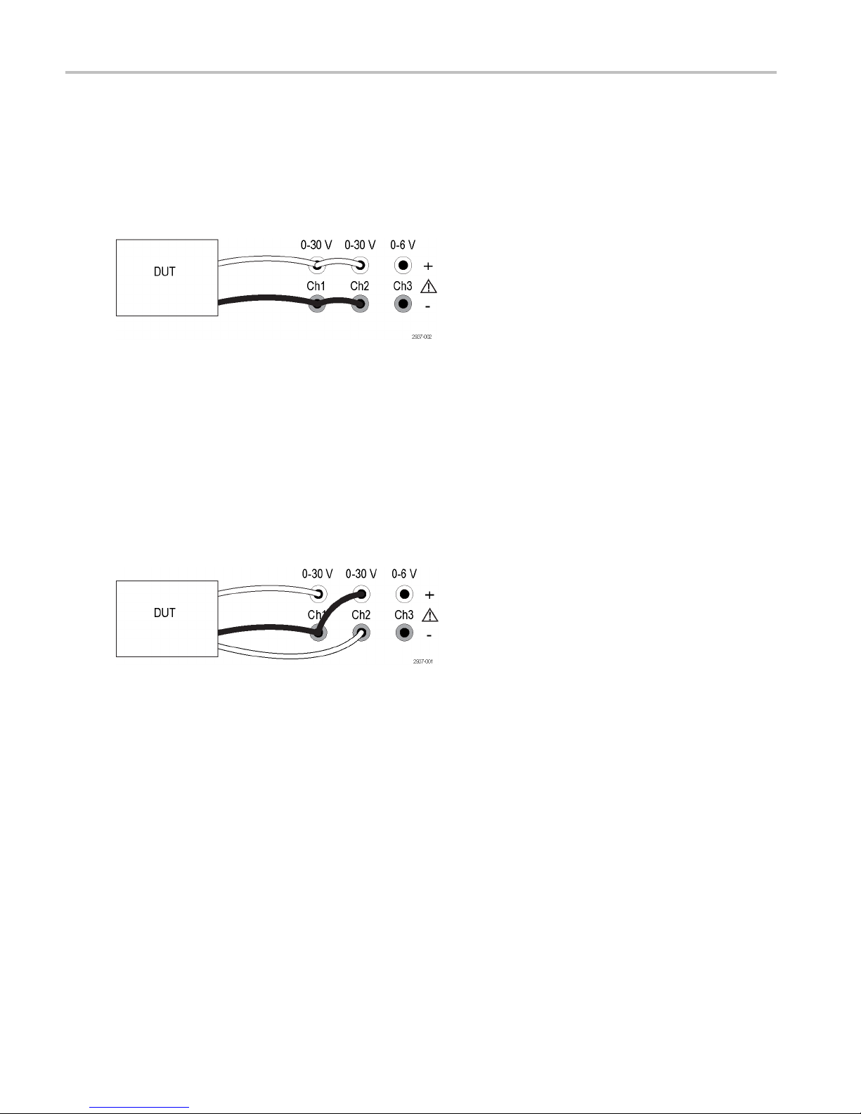
Wiring in Series
By wiring Channel 1 and Channel 2 in series, you can use your power supply to provide up to 60 V to a device under test.
The following figure shows how to wire the outputs for Series operation. (See Figure 3.)
Your instrument can also be configured to read the combined voltage from two channels. See Combine metering of Channel
1 and Channel 2 when outputs are wired i n series to learn how to set the instrument to measure the combined
(See page 18.)
Figure 3: Series setup for model 2230-30-1 and device under test. Series setup for model 2220-30-1 is the same,
but Channel 2 is on the far right.
voltage.
Series 2200 Multi-Channel Programmable DC Power Supplies User Manual 23
Page 34
Operating Basic
Wiring in Parallel
By wiring Channel 1 and Channel 2 in parallel, you can use your power supply to provide up to 3 A to a device under test.
The following figure shows how to wire the outputs for Parallel operation. (See Figure 4.)
Your instrument can also be configured to read the combined current from two channels. See Combine metering of Channel
1 and Channel 2 when outputs are wired in parallel to learn how to set the instrument to measure the combined current.
(See page 18.)
s
Figure 4: P
same, but Channel 2 is on the far right.
arallel setup for model 2230-30-1 and device under test. Parallel setup for model 2220-30-1 is the
Wiring for Bipolar Application s
The outputs of your instrument can be wired as a bipolar source. When testing a system in which independent positive and
negative supplies are needed, the outputs should be wired as shown here. (See Figure 5.)
To make the positive and negative s upplies track together, you can activate tracking. See Use Tracking to learn more about
ng and find out how to turn tracking on. (See page 18.)
tracki
Figure 5: Bipolar setup for model 2230-30-1 and device under test. Bipolar setup for model 2220-30-1 is the same,
hannel 2 is on the far right.
but C
24 Series 2200 Multi-Channel Programmable DC Power Supplies User Manual
Page 35

Index
Index
Symbols and Numbers
110 V/220 V selector switch, 10
15-pin connector, 9
A
Accessorie
s
optional, 1
standard, 1, 2
B
Bipolar wi
Button
ring, 18
Channel select, 6
I-set, 5
Menu, 6
On/off, 6
6
Recall,
Save, 6
V-set, 5
C
l select button, 6
Channe
Channels
combining, 18
ning in parallel, 18
combi
combining in series, 18
Check
nt, 14
curre
no power, 13
voltage, 13
ectivity
Conn
USB, 11
Connector, 15–pin, 9
ectors, 5
Conn
Crossover, 22
Current
stant, 22
con
display, 5
limit adjustment, 16
D
splay, 5
Di
Upper messages, 7
E
Error message
F
Features, iii
Front-panel, 11
indicators
Function button
Channel select, 6
I-set, 5
Menu, 6
On/off, 6
Recall, 6
Save, 6
V-set, 5
I
tton, 5
I-set b u
Installation, 12
K
Key
5
arrow,
function, 5
number, 5
Save an
Key S ound, 20
Knob
Lock S
multipurpose, 5
d Recall, 5
et, 20
L
Local sense, 22
M
Volt Set, 17
Max
Menu button, 6
Messages, 7
or, 7
err
Multipurpose
knob, 5
ob lock, 20
Kn
s, 7
and buttons, 5
N
No power, 13
O
On/off button, 6
Operating requirements, 4
Operation
current limit adjustment, 16
recalling setups, 16
saving set
voltage limit adjustment, 16
Optional accessories, 1
Options, 1
Output
display, 5
Recall, 1
ups, 16
9
P
Parallel wiring, 18
Power
button,
off, 13
on, 12
socket
5
,9
R
Rear-panel, 9
Recall
n, 6
butto
output state at power on, 19
parameters at power on, 19
te sense, 9, 23
Remo
Requirements
operating, 4
S
e button, 6
Sav
Saving and recalling setups, 16
Series wiring, 18
ting
Set
current limit, 16
voltage limit, 16
ttings display, 5
Se
Shorting clip, 9
Specifications, 3
Series 2200 Multi-Channel Programmable DC Power Supplies User Manual 25
Page 36

Index
Standard accessories, 1, 2
T
Troubleshoot
ing, 13
U
USB Device port, 9
V
V-set button, 5
Voltage
constant, 22
display, 5
limit adjustment, 16
setting maxim
um, 17
26 Series 2200 Multi-Channel Programmable DC Power Supplies User Manual
Page 37

Page 38

12/06
Specifications are subject to change without notice.
All Keithley trademarks and trade names are the property of Keithley Instruments, Inc.
All other trademarks and trade names are the property of their respective companies.
A GREATER MEASURE OF CONFIDENCE
Keithley Instruments, Inc.
Corporate Headquarters • 28775 Aurora Road • Cleveland, Ohio 44139 • 440-248-0400 • Fax: 440-248-6168 • 1-888-KEITHLEY • www.keithley.com
 Loading...