

Page 1

tek.com/keithley
S540 Power Semiconductor Test System
Administrative Guide
S540-924-01 Rev. D / January 2019
*PS540-924-01D*
S540-924-01D
Page 2

Power Semiconductor Test System
S540
Administrative Guide
Page 3

© 2019, Keithley Instruments, LLC
Cleveland, Ohio, U.S.A.
All rights reserved.
Any unauthorized reproduction, photocopy, or use of the information herein, in whole or in part,
without the prior written approval of Keithley Instruments, LLC, is strictly prohibited.
These are the original instructions in English.
All Keithley Instruments product names are trademarks or registered trademarks of Keithley
Instruments, LLC. Other brand names are trademarks or registered trademarks of their respective
holders.
Document number: S540-924-01 Rev. D / January 2019
Page 4

Safety precautions
The following safety precautions should be observed before using this product and any associated instrumentation. Although
some instruments and accessories would normally be used with nonhazardous voltages, there are situations where hazardous
conditions may be present.
This product is intended for use by personnel who recognize shock hazards and are familiar with the safety precautions required
to avoid possible injury. Read and follow all installation, operation, and maintenance information carefully before using the
product. Refer to the user documentation for complete product specifications.
If the product is used in a manner not specified, the protection provided by the product warranty may be impaired.
The types of product users are:
Responsible body is the individual or group responsible for the use and maintenance of equipment, for ensuring that the
equipment is operated within its specifications and operating limits, and for ensuring that operators are adequately trained.
Operators use the product for its intended function. They must be trained in electrical safety procedures and proper use of the
instrument. They must be protected from electric shock and contact with hazardous live circuits.
Maintenance personnel perform routine procedures on the product to keep it operating properly, for example, setting the line
voltage or replacing consumable materials. Maintenance procedures are described in the user documentation. The procedures
explicitly state if the operator may perform them. Otherwise, they should be performed only by service personnel.
Service personnel are trained to work on live circuits, perform safe installations, and repair products. Only properly trained
service personnel may perform installation and service procedures.
Keithley products are designed for use with electrical signals that are measurement, control, and data I/O connections, with low
transient overvoltages, and must not be directly connected to mains voltage or to voltage sources with high transient
overvoltages. Measurement Category II (as referenced in IEC 60664) connections require protection for high transient
overvoltages often associated with local AC mains connections. Certain Keithley measuring instruments may be connected to
mains. These instruments will be marked as category II or higher.
Unless explicitly allowed in the specifications, operating manual, and instrument labels, do not connect any instrument to mains.
Exercise extreme caution when a shock hazard is present. Lethal voltage may be present on cable connector jacks or test
fixtures. The American National Standards Institute (ANSI) states that a shock hazard exists when voltage levels greater than
30 V RMS, 42.4 V peak, or 60 VDC are present. A good safety practice is to expect that hazardous voltage is present in any
unknown circuit before measuring.
Operators of this product must be protected from electric shock at all times. The responsible body must ensure that operators
are prevented access and/or insulated from every connection point. In some cases, connections must be exposed to potential
human contact. Product operators in these circumstances must be trained to protect themselves from the risk of electric shock. If
the circuit is capable of operating at or above 1000 V, no conductive part of the circuit may be exposed.
Do not connect switching cards directly to unlimited power circuits. They are intended to be used with impedance-limited
sources. NEVER connect switching cards directly to AC mains. When connecting sources to switching cards, install protective
devices to limit fault current and voltage to the card.
Before operating an instrument, ensure that the line cord is connected to a properly-grounded power receptacle. Inspect the
connecting cables, test leads, and jumpers for possible wear, cracks, or breaks before each use.
When installing equipment where access to the main power cord is restricted, such as rack mounting, a separate main input
power disconnect device must be provided in close proximity to the equipment and within easy reach of the operator.
For maximum safety, do not touch the product, test cables, or any other instruments while power is applied to the circuit under
test. ALWAYS remove power from the entire test system and discharge any capacitors before: connecting or disconnecting
cables or jumpers, installing or removing switching cards, or making internal changes, such as installing or removing jumpers.
Do not touch any object that could provide a current path to the common side of the circuit under test or power line (earth)
ground. Always make measurements with dry hands while standing on a dry, insulated surface capable of withstanding the
voltage being measured.
Page 5
For safety, instruments and accessories must be used in accordance with the operating instructions. If the instruments or
accessories are used in a manner not specified in the operating instructions, the protection provided by the equipment may be
impaired.
Do not exceed the maximum signal levels of the instruments and accessories. Maximum signal levels are defined in the
specifications and operating information and shown on the instrument panels, test fixture panels, and switching cards.
When fuses are used in a product, replace with the same type and rating for continued protection against fire hazard.
Chassis connections must only be used as shield connections for measuring circuits, NOT as protective earth (safety ground)
connections.
If you are using a test fixture, keep the lid closed while power is applied to the device under test. Safe operation requires the use
of a lid interlock.
The symbol on an instrument means caution, risk of hazard. The user must refer to the operating instructions located in the
user documentation in all cases where the symbol is marked on the instrument.
The symbol on an instrument means warning, risk of electric shock. Use standard safety precautions to avoid personal
contact with these voltages.
The symbol on an instrument shows that the surface may be hot. Avoid personal contact to prevent burns.
The symbol indicates a connection terminal to the equipment frame.
If this symbol is on a product, it indicates that mercury is present in the display lamp. Please note that the lamp must be
properly disposed of according to federal, state, and local laws.
The WARNING heading in the user documentation explains hazards that might result in personal injury or death. Always read
the associated information very carefully before performing the indicated procedure.
The CAUTION heading in the user documentation explains hazards that could damage the instrument. Such damage may
invalidate the warranty.
The CAUTION heading with the symbol in the user documentation explains hazards that could result in moderate or minor
injury or damage the instrument. Always read the associated information very carefully before performing the indicated
procedure. Damage to the instrument may invalidate the warranty.
Instrumentation and accessories shall not be connected to humans.
Before performing any maintenance, disconnect the line cord and all test cables.
To maintain protection from electric shock and fire, replacement components in mains circuits — including the power
transformer, test leads, and input jacks — must be purchased from Keithley. Standard fuses with applicable national safety
approvals may be used if the rating and type are the same. The detachable mains power cord provided with the instrument may
only be replaced with a similarly rated power cord. Other components that are not safety-related may be purchased from other
suppliers as long as they are equivalent to the original component (note that selected parts should be purchased only through
Keithley to maintain accuracy and functionality of the product). If you are unsure about the applicability of a replacement
component, call a Keithley office for information.
Unless otherwise noted in product-specific literature, Keithley instruments are designed to operate indoors only, in the following
environment: Altitude at or below 2,000 m (6,562 ft); temperature 0 °C to 50 °C (32 °F to 122 °F); and pollution degree 1 or 2.
To clean an instrument, use a cloth dampened with deionized water or mild, water-based cleaner. Clean the exterior of the
instrument only. Do not apply cleaner directly to the instrument or allow liquids to enter or spill on the instrument. Products that
consist of a circuit board with no case or chassis (e.g., a data acquisition board for installation into a computer) should never
require cleaning if handled according to instructions. If the board becomes contaminated and operation is affected, the board
should be returned to the factory for proper cleaning/servicing.
Safety precaution revision as of June 2017.
Page 6

S540 system ............................................................................................................. 1-1
Table of contents
Introduction .......................................................................................................................... 1-1
Systems documentation ....................................................................................................... 1-1
System description ............................................................................................................... 1-1
Optional accessories ............................................................................................................ 1-3
S540 site preparation and installation .................................................................... 2-1
Site preparation checklist ..................................................................................................... 2-1
Unpacking the S540 system ................................................................................................ 2-2
Unpacking system components ................................................................................................ 2-3
Unpacking the S540 system accessories ................................................................................ 2-12
Keithley field service engineer installation tasks ................................................................ 2-15
Example Series 500 System Installation Form ........................................................................ 2-16
Power and operating conditions ......................................................................................... 2-19
Supplied power cords .............................................................................................................. 2-19
Line power requirements ......................................................................................................... 2-19
System power dissipation........................................................................................................ 2-20
Operating environment conditions ........................................................................................... 2-20
Triaxial connector handling and avoiding contamination ................................................... 2-21
Lockout and tagout ............................................................................................................. 2-21
Installation and connections ............................................................................................... 2-23
Position the system cabinet..................................................................................................... 2-23
Cable harness routing ............................................................................................................. 2-24
Floor plan ........................................................................................................................... 2-24
System cabinet size and weight ......................................................................................... 2-26
Physically securing the system .......................................................................................... 2-27
Optional advanced seismic securement ............................................................................ 2-29
Equipment startup ................................................................................................... 3-1
Introduction .......................................................................................................................... 3-1
Initial equipment startup ....................................................................................................... 3-1
System startup ..................................................................................................................... 3-2
Before starting system software ........................................................................................... 3-3
Using Telnet .............................................................................................................................. 3-3
Start the KTE software ......................................................................................................... 3-4
IC process log messages .......................................................................................................... 3-4
Stopping the IC process ............................................................................................................ 3-4
Start the ACS software......................................................................................................... 3-5
Shut down using ACS .......................................................................................................... 3-5
Shut down using KTE ........................................................................................................... 3-6
Page 7

Table of contents S540 Power Semiconductor Test System Administrative Guide
Emergency OFF button ........................................................................................................ 3-6
Emergency shutdown procedure ............................................................................................... 3-6
Recovering from an emergency shutdown ................................................................................ 3-7
Safety interlocks ................................................................................................................... 3-7
Additional probe card adapter safety interlock cable ................................................................. 3-9
9140A-PCA interlock connections for S540 systems .............................................................. 3-10
LO patch panel ................................................................................................................... 3-11
Prober safety ...................................................................................................................... 3-11
Network information ........................................................................................................... 3-12
Maintenance ............................................................................................................. 4-1
Hardware replacement ......................................................................................................... 4-1
Handling and cleaning precautions ...................................................................................... 4-2
Special handling of static-sensitive devices .............................................................................. 4-3
Electrical hazard tasks ......................................................................................................... 4-3
Types of electrical hazard tasks ................................................................................................ 4-4
Repair and replacement ............................................................................................................ 4-4
Instrument removal and installation ..................................................................................... 4-4
Remove system power .............................................................................................................. 4-4
Heavy instrument removal and installation ................................................................................ 4-5
General replacement procedure ................................................................................................ 4-6
Adjustment ................................................................................................................................ 4-7
Restore system power .............................................................................................................. 4-7
Fuses ........................................................................................................................................ 4-8
Power distribution and emergency off .................................................................................. 4-9
Power distribution unit connections and power distribution basics .......................................... 4-10
System emergency off circuit .................................................................................................. 4-12
Data hub license ................................................................................................................ 4-13
Editing the icconfig_<QMO>.ini file .................................................................................... 4-13
Using NPLCs to adjust speed and accuracy ..................................................................... 4-14
Setting the number of power line cycles .................................................................................. 4-14
Setting a custom system speed .............................................................................................. 4-15
NPLC default differences ........................................................................................................ 4-15
Decommissioning an S540 test system ............................................................................. 4-16
Instrument specifications and documentation ...................................................... 5-1
Introduction .......................................................................................................................... 5-1
Switching .............................................................................................................................. 5-2
Model 707B Switch Matrix Mainframe ....................................................................................... 5-2
HVM1212A High-Voltage Switch Matrix .................................................................................... 5-2
Sourcing and measuring ...................................................................................................... 5-3
Model 2657A High-Power System SourceMeter Instrument ..................................................... 5-3
Optional instrumentation ...................................................................................................... 5-4
Typical matrix connections ................................................................................................... 5-4
S540 3000 V high-voltage system ............................................................................................. 5-5
S540 3000 V high-voltage, low-current system ......................................................................... 5-6
Page 8

S540 Power Semiconductor Test System Administrative Guide Table of contents
S540 high-voltage, low-current system using an RSA306B spectrum analyzer ........................ 5-7
S540 KTE communications .................................................................................................. 5-8
S540 ACS communications diagrams ................................................................................. 5-9
Page 9

In this section:
Introduction .............................................................................. 1-1
Systems documentation ........................................................... 1-1
System description ................................................................... 1-1
Optional accessories ................................................................ 1-3
Introduction
Section 1
S540 system
If you have any questions after reviewing this information, please contact your local Keithley
Instruments office, sales partner, or distributor. You can also call the corporate headquarters of
Keithley Instruments (toll-free inside the U.S. and Canada only) at 1-800-935-5595, or from outside
the U.S. at +1-440-248-0400. For worldwide contact numbers, visit the Keithley Instruments website
(tek.com/keithley).
Systems documentation
Documentation for your system is available at tek.com/keithley. Following is a list of documentation
for your system, including the document part numbers.
S540 Power Semiconductor Test System Administrative Guide (S540-924-01)
S540 Power Semiconductor Test System Reference Manual (S540-901-01)
Keithley Test Environment (KTE) Programmer's Manual (S500-904-01)
System description
The Keithley Instruments S540 Power Semiconductor Test System is a configurable,
instrument-based system for power semiconductor parametric characterization and testing. There are
two different S540 systems available:
S540 3000 V high-voltage parametric test system with a 3-kV switching matrix (12 pins)
S540 3000 V high-voltage, low-current parametric test system with a 3-kV switching matrix
(12 pins) and a low-current switching matrix (12, 24, or 36 pins)
Page 10
Section 1: S540 system S540 Power Semiconductor Test System Administrative Guide
1-2
The S540 systems have flexible hardware configurations that allow you to customize them to your
S540 3000 V high-voltage system configuration options
DC source-measure units (SMU)
Maximum number of SMUs depends on other items in
the system rack
Model 2636B System SourceMeter
®
instrument
(quantity: 0 to 4)
Model 2657A High-Power System SourceMeter
®
instrument (quantity: 2)
Switching matrices
One Model HVM1212A 12 × 12 high-voltage switch matrix
Optional capacitance/voltage (C-V)
One channel of C-V (using one Model 4200A-SCS with one
Model 4210-CVU card)
Optional instruments
Model 4220-PGU dual-channel pulse cards (quantity: 0 to
3)
RSA306B USB Spectrum Analyzer (quantity: 0 to 1) for
frequency and ring oscillator measurements
Included with each system
Computer inside cabinet
External 24-inch flat-panel monitor and keyboard tray
mounted on exterior of cabinet
Keithley Test Environment (KTE) or Automated
Characterization Suite (ACS) system software
LO patch panel
Safety interlock system
Adjustable cable support arm
Other options
Advanced seismic securement kit for additional resistance to
seismic forces
specific needs. See the following table for a description of the main system configuration options, and
see the following figure for an example of a typical system configuration.
S540-924-01 Rev. D / January 2019
Page 11
S540 Power Semiconductor Test System Administrative Guide Section 1: S540 system
1-3
S540 3000 V high-voltage, low-current system configuration options
DC source-measure units (SMU)
Maximum number of units depends on other items in the
system rack
2636B System SourceMeter
®
instrument (quantity: 1 to 4)
2657A High-Power System SourceMeter
®
instrument
(quantity: 2)
6-slot switching matrix
One Model HVM1212A 12 × 12 high-voltage switch matrix and
one Model 707B system switch mainframe with:
Model 7531 switch cards (quantity: 2 to 6, depending on
instruments and number of low-voltage pins in the
system); one card is used as an interconnect card
Optional capacitance/voltage (C-V)
Two channels of C-V (using one Model 4200A-SCS with two
Model 4210-CVU cards)
Optional instruments
Model DMM7510 7-1/2 Digit Graphical Sampling
Multimeter
(quantity: 0 to 1)
Model 4220-PGU dual-channel pulse cards (quantity: 0 to
3)
Frequency measurement option
Included with each system
Computer inside cabinet
External 24-inch flat-panel monitor and keyboard tray
mounted on exterior of cabinet
Keithley Test Environment (KTE) or Automated
Characterization Suite (ACS) system software
LO patch panel
Interlock system
Adjustable cable support arm
Other options
Advanced seismic securement kit for additional resistance to
seismic forces
Optional accessories
Optional items and accessories that may accompany the S540 system:
Cables to connect to the test fixture or the probe card adapter
9140A-PCA probe card adapter (12 3-kV pins to 36 200-V pins) or Celadon Systems
VersaCoreTM VC20 probe card adapter (12 3-kV pins to 32 200-V pins)
RSA306B USB Spectrum Analyzer
Advanced seismic securement kit
S540-924-01 Rev. D / January 2019
Page 12
In this section:
Site preparation checklist ......................................................... 2-1
Unpacking the S540 system..................................................... 2-2
Keithley field service engineer installation tasks .................... 2-15
Power and operating conditions ............................................. 2-19
Triaxial connector handling and avoiding contamination ........ 2-21
Lockout and tagout ................................................................. 2-21
Installation and connections ................................................... 2-23
Floor plan ............................................................................... 2-24
System cabinet size and weight ............................................. 2-26
Physically securing the system .............................................. 2-27
Optional advanced seismic securement ................................. 2-29
Site preparation checklist
S540 system preparation checklist
Site
Item
Is it necessary to have lifting equipment?
Is the flooring adequate and able to support the weight of the system while moving from receiving to the final
destination (see Floor plan (on page 2-24) for specifications)?
Are all of the corridors and hallways large enough to allow clearance for the system?
Are stairways adequate for moving the system through?
Are elevators needed to move the system? Can they support the size and weight of the system?
Are the doorways wide enough for the system?
If you are using a Keithley probe card adapter, you must supply a vacuum connection (50.80 cm Hg / 20 in.).
Floor plan
Item
Did you complete the system layout (see Floor plan (on page 2-24) for specifications)?
Does your layout show all of the locations for all of the equipment?
Does your system layout show the locations of all doors and aisles?
Does your layout allow for the proper clearance of the system for the front, rear, and the keyboard/monitor
arm?
Is there enough space for personnel safety, comfort, and freedom of movement?
Section 2
S540 site preparation and installation
The following site preparation checklist will help you prepare your site for the S540 system in your
facility. If you find that an item listed is not valid for your site, you can indicate it with "N/A."
Page 13
Section 2: S540 site preparation and installation S540 Power Semiconductor Test System Administrative Guide
2-2
S540 system preparation checklist (continued)
Floor plan
Did you take future expansions into consideration?
Electrical
power
Item
Is there sufficient space for any supplies or manuals?
Is adequate and proper electrical power available (see Line power requirements (on page 2-19) for
specifications)?
Is anything connected to the same power source that generates noise?
Is anything that requires substantial amounts of current connected to the same power source?
Did you prepare power outlets for service, testing, or maintenance?
Unpacking the S540 system
The Keithley field service engineer (FSE) is responsible for unpacking the S540 system cabinet and
the accessories. However, we recommend that you move the crate and the accessories box to the
area where the system is going to be used.
Here is a list of tools needed for unpacking:
Safety glasses
Gloves
Standard screwdriver
Socket wrench
Socket head: 19 mm (3/4 in.)
S540-924-01 Rev. D / January 2019
Page 14
S540 Power Semiconductor Test System Administrative Guide Section 2: S540 site preparation and installation
2-3
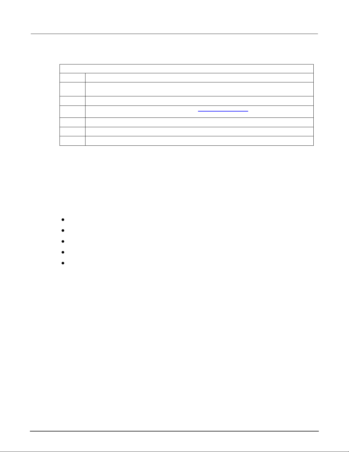
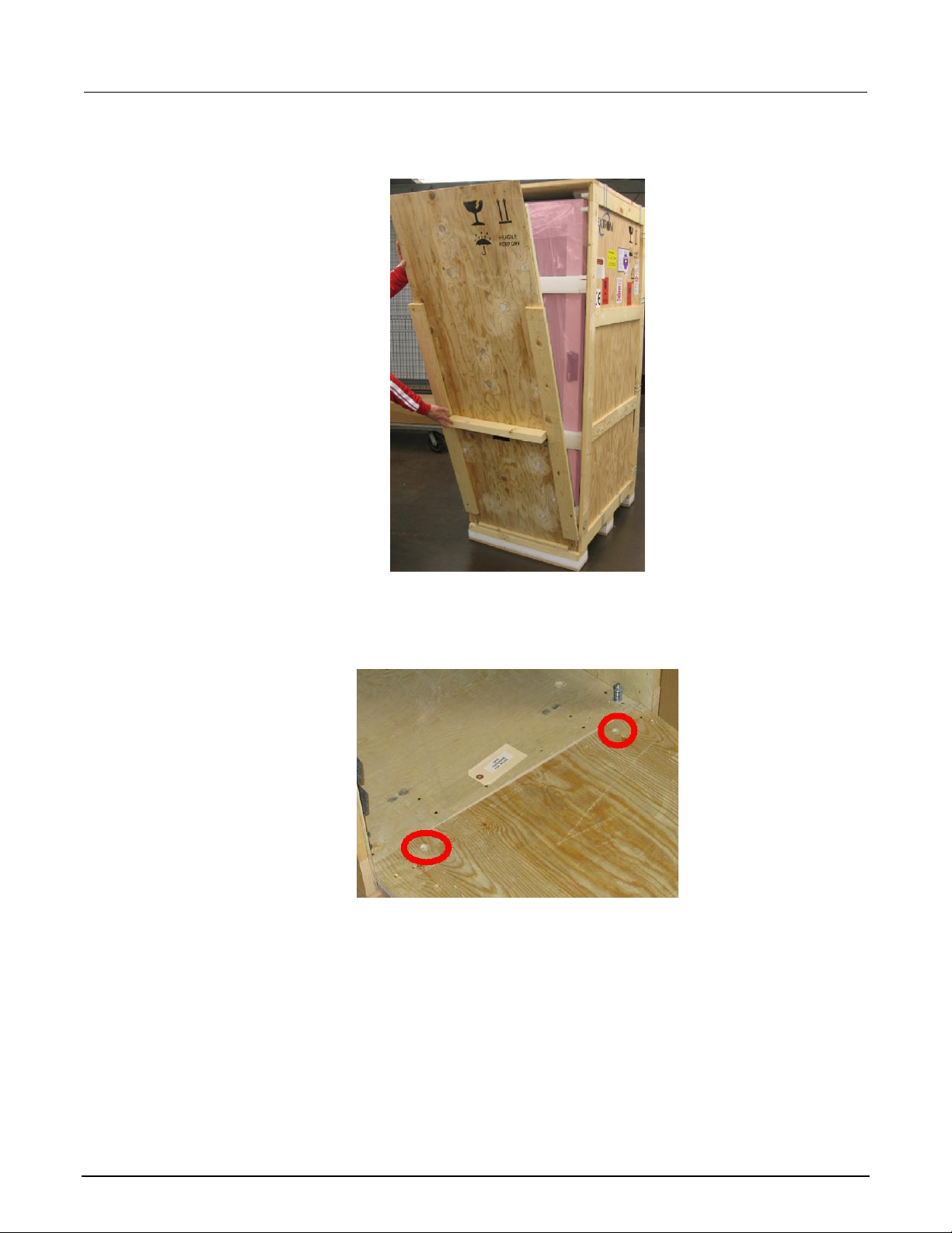
The following information will help the FSE unpack the system. Series 500 systems are shipped in a
wooden crate (see the following figure).
Figure 1: S540 system cabinet in shipping crate
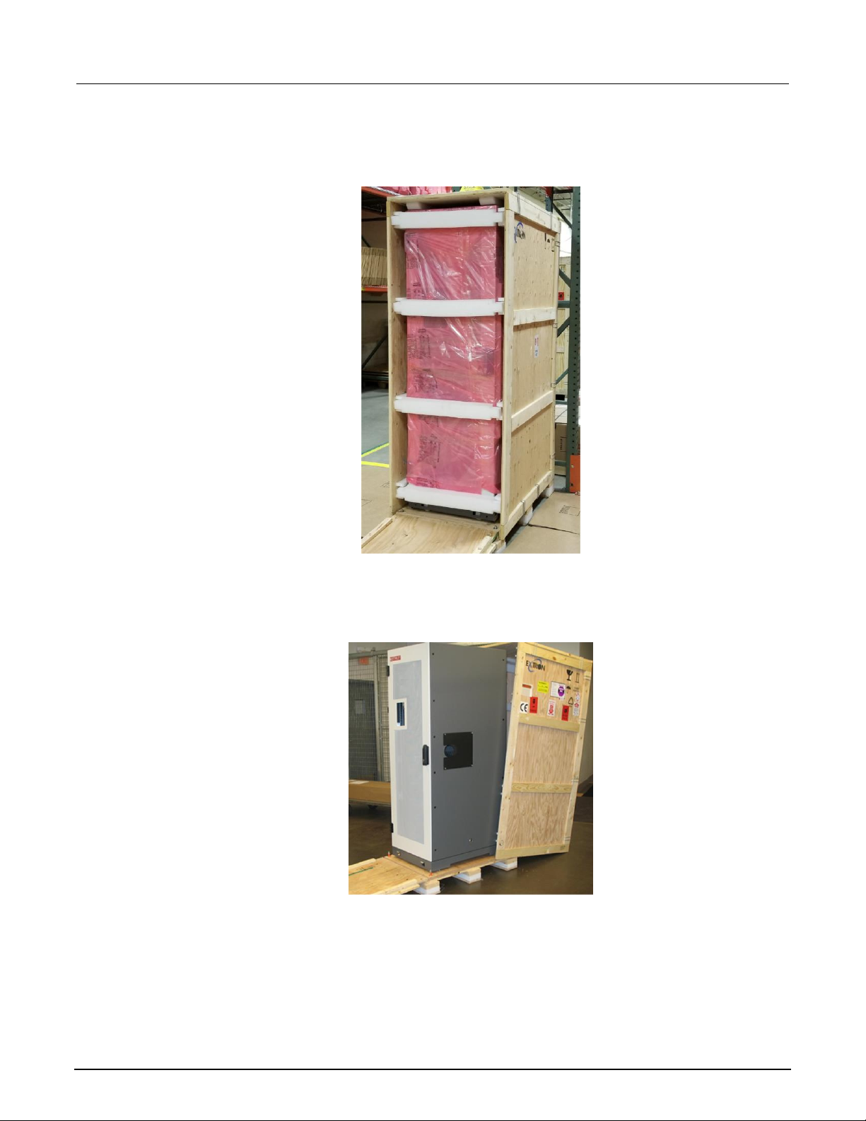
Unpacking system components
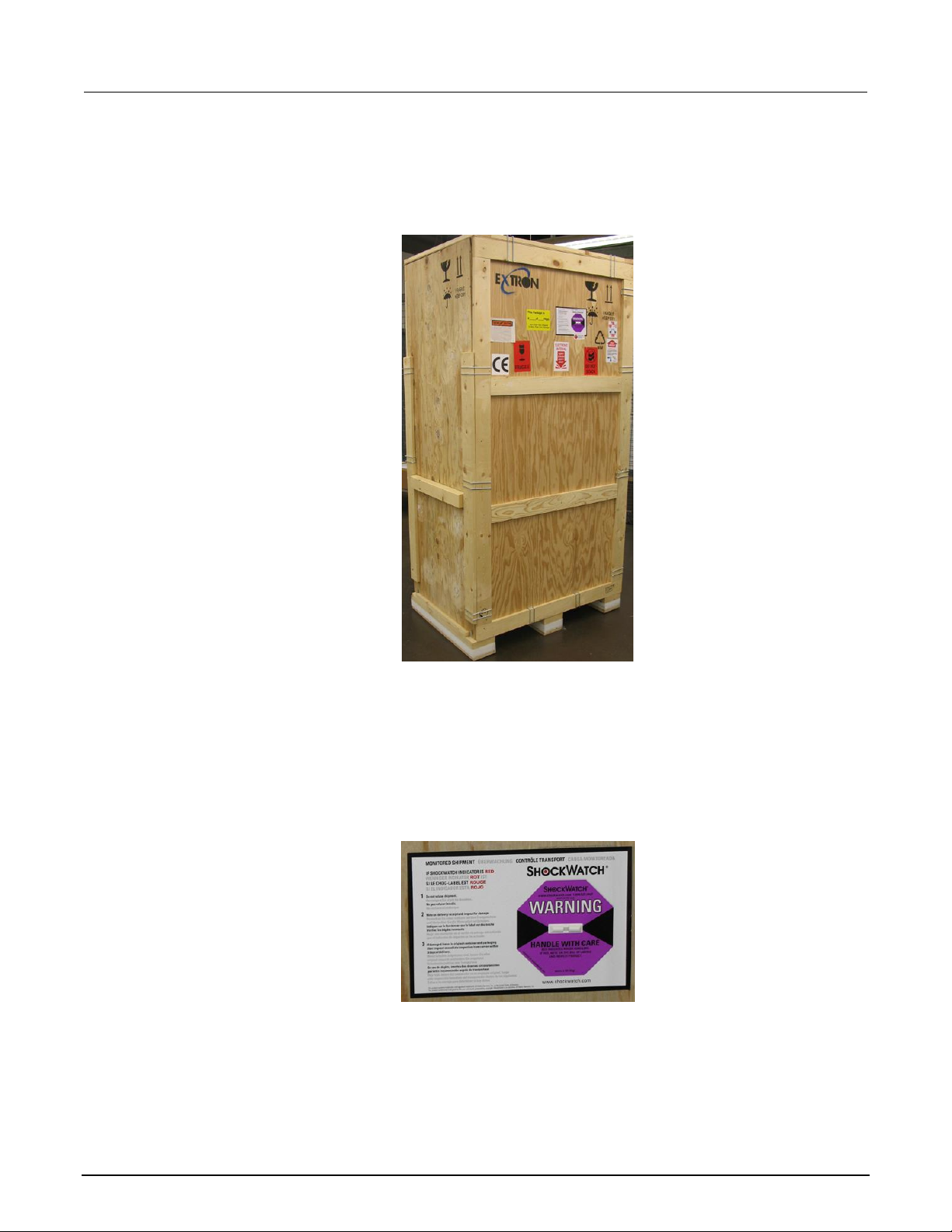
Inspect the shock sensor on the outside of the shipping crate (see the following figure). If the shock
sensor indicates a shock condition, do a thorough inspection of all components in the system cabinet.
Figure 2: S540 crate shock sensor
S540-924-01 Rev. D / January 2019
Page 15
Section 2: S540 site preparation and installation S540 Power Semiconductor Test System Administrative Guide
2-4
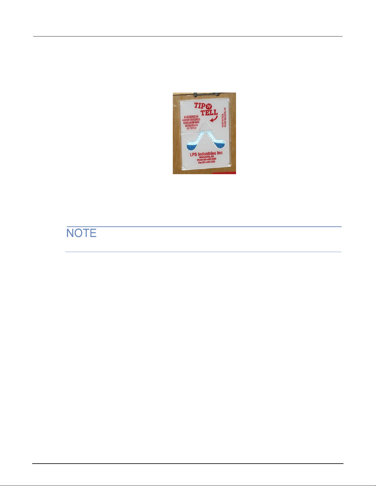
Also, check the "TIP N TELL" indicator to ensure that the crate has not been tipped over (see the
following figure).
Figure 3: S540 crate tipping indicator
Carefully remove all system components from the crate. While unpacking, make sure there is no
component damage. Report any damage to the shipping agent immediately. Please reuse or recycle
packaging materials in accordance with your local requirements.
You need at least two people to unpack and move the S540 system cabinet.
S540-924-01 Rev. D / January 2019
Page 16
S540 Power Semiconductor Test System Administrative Guide Section 2: S540 site preparation and installation
2-5
To unpack the system components:
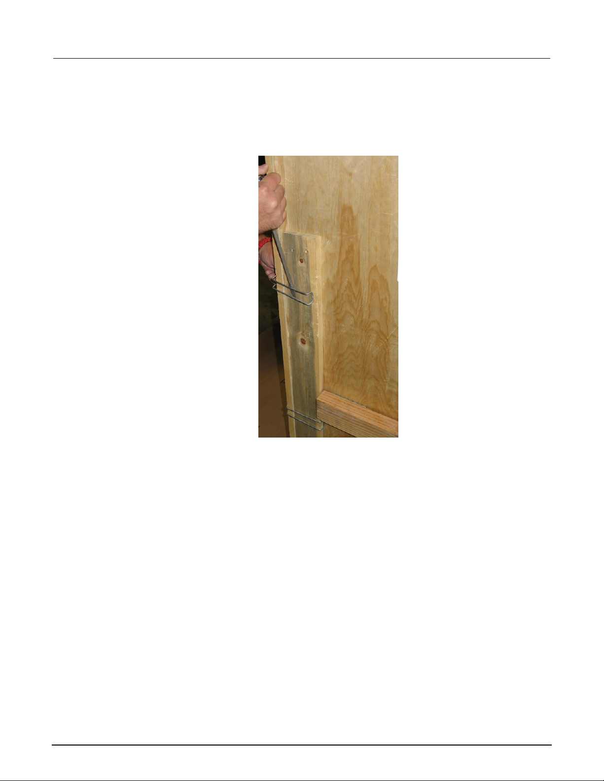
1. Remove the crate clamps from the crate using a standard screwdriver.
Figure 4: Removing the crate clamps
2. Open the front of the crate. The front is identified by the wooden ramp support attached across
the panel (see the following figure).
3. Make sure the ramp support is pulled away from the crate. It is held in place with hook and loop
fasteners (such as Velcro®).
S540-924-01 Rev. D / January 2019
Page 17
Section 2: S540 site preparation and installation S540 Power Semiconductor Test System Administrative Guide
2-6
Figure 5: Opening the front of the crate
4. Attach the ramp using the two bolts that are attached to the bottom front of the crate.
Figure 6: Front of the crate with ramp down
S540-924-01 Rev. D / January 2019
Page 18
S540 Power Semiconductor Test System Administrative Guide Section 2: S540 site preparation and installation
2-7
5. Remove the padding from the front of the S540 system cabinet.
Figure 7: Removing the padding
6. Remove the crate clamps and slide the outer box cover off the crate.
Figure 8: Sliding the outer box off the crate
S540-924-01 Rev. D / January 2019
Page 19
Section 2: S540 site preparation and installation S540 Power Semiconductor Test System Administrative Guide
2-8
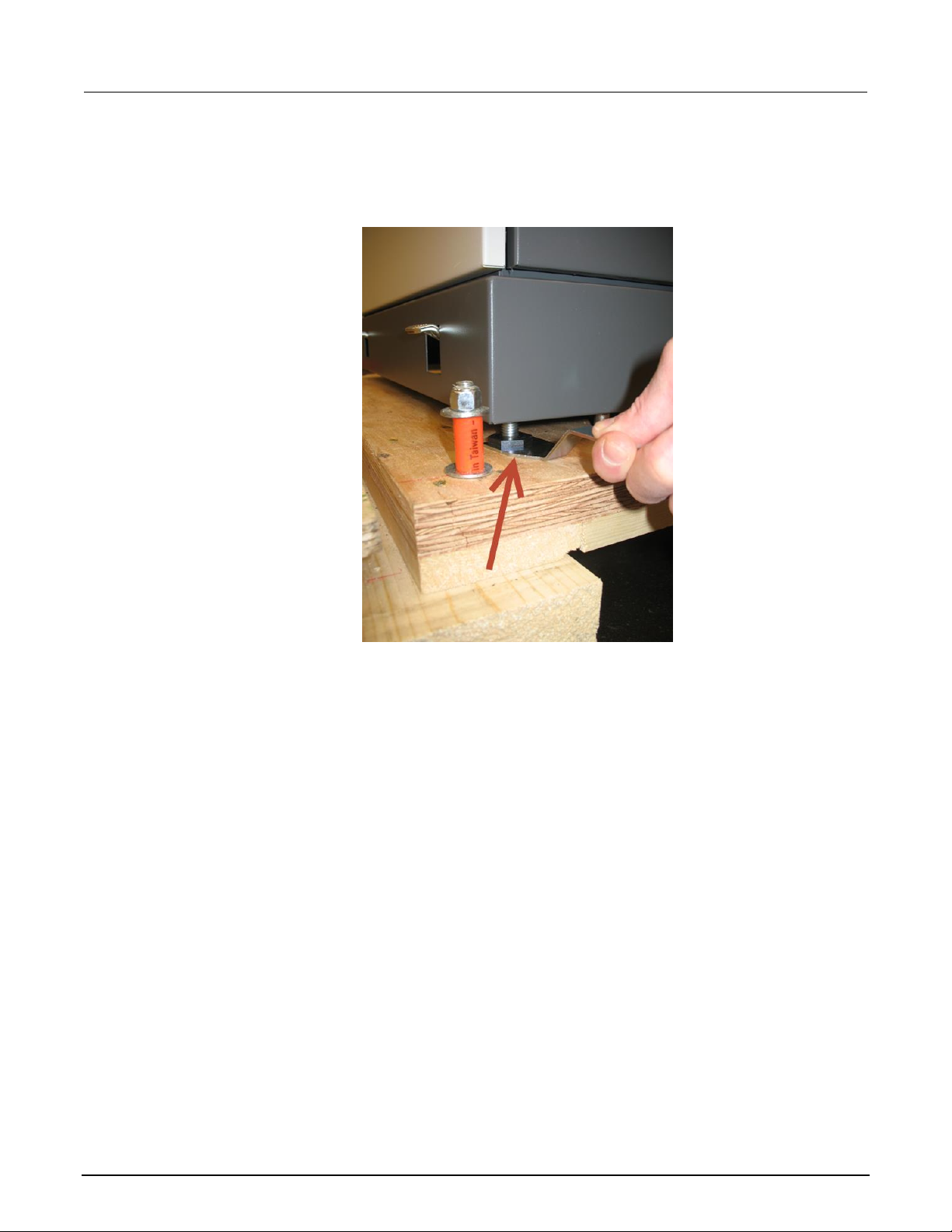
7. Make sure that you retract the leveling feet on the bottom of the system (next to the casters) to
put weight on the casters and prepare the system to be rolled down the ramp.
Figure 9: Leveling feet
S540-924-01 Rev. D / January 2019
Page 20
S540 Power Semiconductor Test System Administrative Guide Section 2: S540 site preparation and installation
2-9
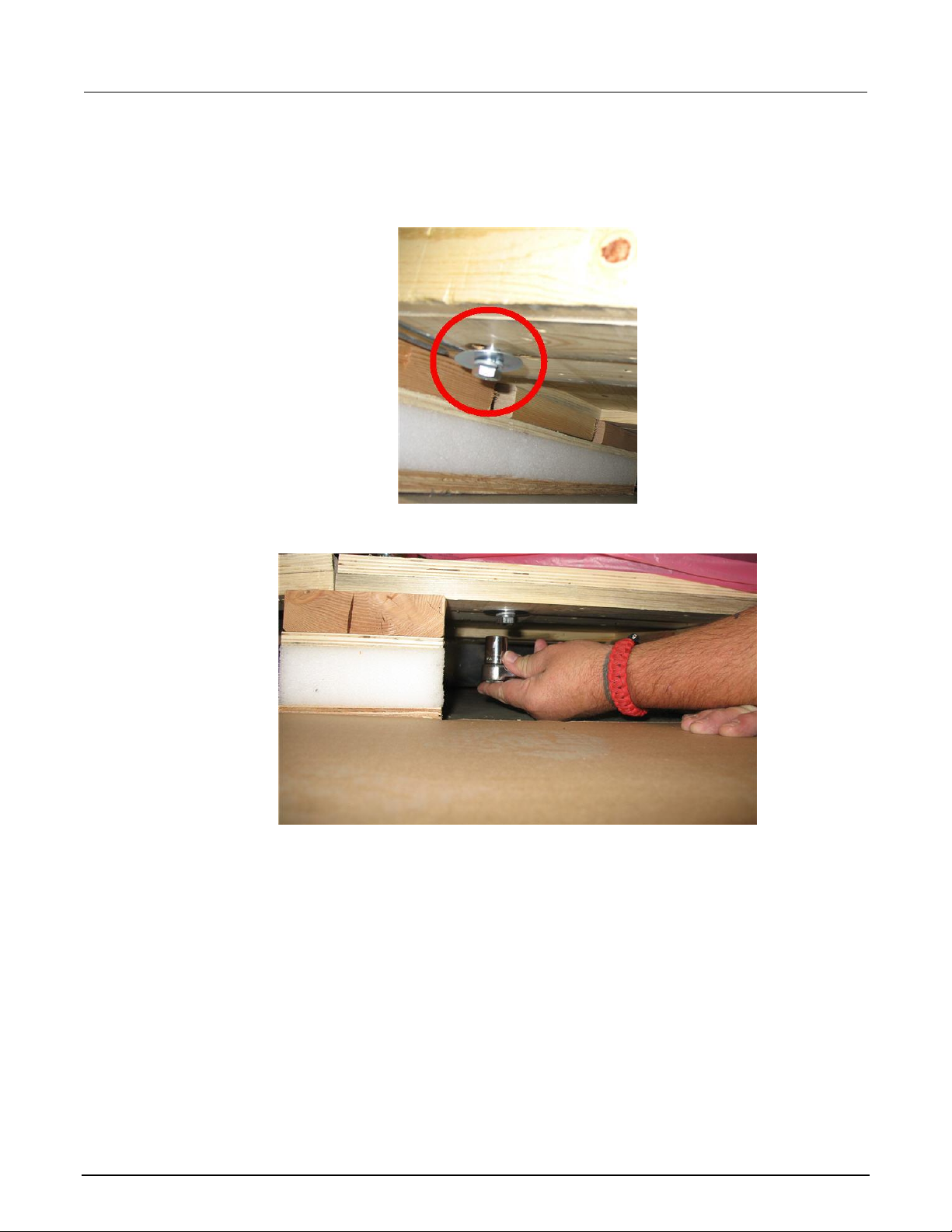
8. Remove the four bolts from the bottom of the crate that are attached to the bottom of the S540
system cabinet using a 19 mm socket head on a socket wrench.
Figure 10: System bolted to the crate
Figure 11: Removing the bolts from the crate
S540-924-01 Rev. D / January 2019
Page 21
Section 2: S540 site preparation and installation S540 Power Semiconductor Test System Administrative Guide
2-10
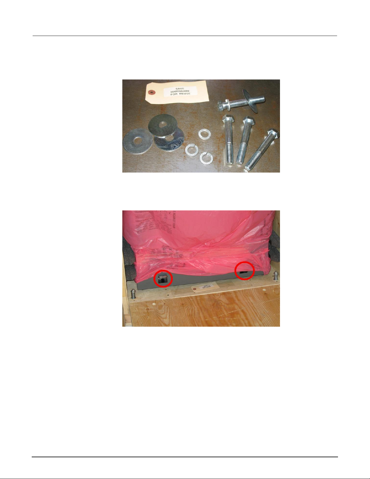
9. Save the hardware (the four bolts and washers) that you remove from the bottom of the crate.
Figure 12: System crate hardware
10. Unlock the two casters that are on the front of the S540 system cabinet by moving the locks up.
Figure 13: System caster brakes
S540-924-01 Rev. D / January 2019
Page 22

S540 Power Semiconductor Test System Administrative Guide Section 2: S540 site preparation and installation
2-11
11. With two people, slide the S540 system cabinet down the ramp.
Figure 14: Rolling the system down the ramp
12. Remove the tape from the packing material using scissors, taking care not to scratch the S540
system cabinet.
Figure 15: Cutting the wrap off the system
13. Move the S540 system cabinet to its final destination.
The system cabinet is shipped from the factory with all of the instruments installed. Most equipment
connections and wiring of instruments in the system cabinet was done at the factory.
S540-924-01 Rev. D / January 2019
Page 23
Section 2: S540 site preparation and installation S540 Power Semiconductor Test System Administrative Guide
2-12
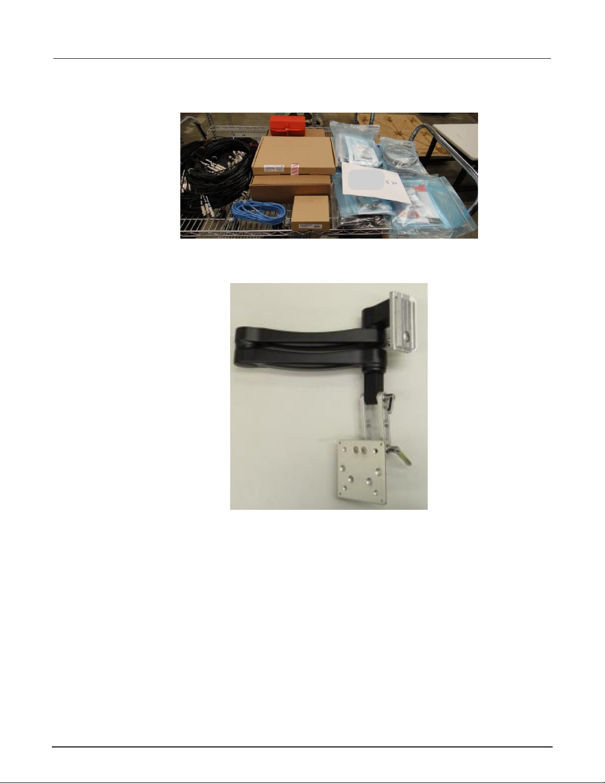
Unpacking the S540 system accessories
The accessories are shipped in a separate box or in multiple boxes, depending on how many
accessories are ordered.
Figure 16: S540 system accessories
The accessories box contains a computer monitor, keyboard, and mouse. It also includes required
installation hardware, USB extension cables, cable support arm, connectors for the keyboard and
mouse, and any other accessories that may have been ordered with the system (for example, probe
card adapter, cables to connect to the test fixture or probe card adapter, or advanced seismic
securement kit). You will also find all of the documentation that is shipped with your order. Please
reuse or recycle packaging materials in accordance with your local requirements.
The following figures are examples of system accessories that may be included in your shipment.
What you receive may be different depending on your system configuration.
S540-924-01 Rev. D / January 2019
Page 24
S540 Power Semiconductor Test System Administrative Guide Section 2: S540 site preparation and installation
2-13
Figure 17: Typical system accessories
Figure 18: Monitor arm accessory
S540-924-01 Rev. D / January 2019
Page 25

Section 2: S540 site preparation and installation S540 Power Semiconductor Test System Administrative Guide
2-14
Figure 19: Keyboard tray and arm accessory
Figure 20: Cable support arm accessory
S540-924-01 Rev. D / January 2019
Page 26

S540 Power Semiconductor Test System Administrative Guide Section 2: S540 site preparation and installation
2-15
Chuck cables for optional probe card adapters
Model
Quantity
Description
CA-63-12
2
12 ft three-lug triaxial cables
237-TRX-T
1
Three-slot male to dual three-lug female triaxial tee adapter
237-BNC-TRX
1
High-voltage two-slot BNC to three-lug female triaxial adapter
A set of chuck cables is included with the optional 9140A-PCA probe card adapter. Model numbers of
cables vary based on the prober you are using. For example, the Keithley Field Service Engineer
(FSE) will install the cables shown in the following table for Tel P8 probers.
If a different cable termination scheme is required, a customer-supplied solution can be used.
Optional probe card adapter vacuum requirement
9140A-PCA probe card adapter requirement: A 50.80 cm (20 in.) Hg (which is the same as 40.73 PSI)
vacuum supply, with a hose connection of 0.64 cm (1/4 in.) outside diameter and 0.32 cm (1/8 in.)
inside diameter.
For detailed information about the 9140A-PCA probe card adapter, see the 9140A-PCA Probe Card
Adapter Instruction Manual (part number 9140A-901-01). This manual is available for download at
tek.com/keithley.
Keithley field service engineer installation tasks
The Keithley field service engineer (FSE) will perform the following tasks:
Unpack the system components and accessories.
Attach the keyboard arm and monitor arm to the system.
Install the keyboard and the mouse on the keyboard arm, and the monitor on the monitor arm.
Install the cable support arm to the system.
Install the probe card assembly (PCA) (if ordered) on the back of the system cabinet, and the
60190-PCA (probe card assembly) to the correct prober plate (customer-supplied from the prober
company). The prober plate is attached to the prober.
Plug in the system to your power facilities (supplied by your facilities department at the final
location for the S540 system cabinet) and power up the entire cabinet.
Verify communications of all instruments and with the properly configured prober.
Perform diagnostics and system verification tests of the entire S540 system, to include the
60190-PCA (if ordered).
Record all the information on the System Installation Form.
S540-924-01 Rev. D / January 2019
Page 27

Section 2: S540 site preparation and installation S540 Power Semiconductor Test System Administrative Guide
2-16
Example Series 500 System Installation Form
Figure 21: Example Series 500 System Installation Form page 1
S540-924-01 Rev. D / January 2019
Page 28

S540 Power Semiconductor Test System Administrative Guide Section 2: S540 site preparation and installation
2-17
Figure 22: Example Series 500 System Installation Form page 2
S540-924-01 Rev. D / January 2019
Page 29

Section 2: S540 site preparation and installation S540 Power Semiconductor Test System Administrative Guide
2-18
Figure 23: Example Series 500 System Installation Form page 3
S540-924-01 Rev. D / January 2019
Page 30

S540 Power Semiconductor Test System Administrative Guide Section 2: S540 site preparation and installation
2-19
Power and operating conditions
Number
Description
1
20 A, 125 V American
2
15 A, 125 V American
3
16 A, 250 V Eurostyle cord
The following topics contain information about power and operating environment conditions.
Supplied power cords
Keithley Instruments provides power cords that match the power requirements of the system. The
following figure and table describe these cords.
Figure 24: Supplied power cables
If power cords with different cord ends are needed, you must provide those cords.
Line power requirements
Nominal input line voltage: 100 VAC, 115 VAC, 220 VAC, 240 VAC (50 Hz, 60 Hz)
Short-circuit current rating: 5 kA
Power consumption: Rated at 2.4 kVA for the 2 kW power distribution unit (PDU)
Heat generation: Quiescent heat of 1720 BTU (1815 kJ) to maximum heat of 8191 BTU (8642 kJ)
S540-924-01 Rev. D / January 2019
Page 31

Section 2: S540 site preparation and installation S540 Power Semiconductor Test System Administrative Guide
2-20
Severe personal injury or death due to electric shock or electrocution or equipment damage
may occur if you do not have the correct circuit amperage.
S540 systems that are configured to operate between 100 VAC and 120 VAC must use a 20 A
circuit; systems that are configured to operate between 200 VAC and 240 VAC must use a
15 A circuit.
System power dissipation
The total power dissipated by the S540 depends on the type and number of instruments in the test
system. The power distribution unit (PDU) limits the incoming power to these instruments.
Though the PDU ensures electrical safety and compliance to the required standards, it does not
prevent the system from overheating.
When a Series 2600B or 2657A instrument detects an excessive heat condition, the instrument turns
the output off to minimize power dissipation. This safeguard prevents damage to individual Series
2600B and 2657A instruments, but may result in test instability. For instance, if you continuously
source more than 1 A from all the source-measure units (SMUs) for more than 100 seconds, it may
trigger a temperature error in one or more of the Series 2600B or 2657A instruments. However, an
average output of less than 1 A for an indefinite period will not cause a temperature error.
For additional information about the Keithley Instruments Series 2600B and 2657A SourceMeter®
instruments, refer to the documentation at tek.com/keithley.
Operating environment conditions
To ensure operation within specifications, the S540 must be operated inside of the following
environmental conditions.
Temperature: 23 °C ±5 °C
Operating humidity: 30% to 60% relative humidity, noncondensing, after a two-hour warm up time
Vibration: High ambient vibration levels may require isolation pads or the repositioning of equipment
Air quality: The S540 system is compatible for use in a Class 10 clean room
Audible system noise: Decibel level is 65 dBA in optimal environmental conditions
Airflow: The S540 system is configured for top to bottom airflow
Altitude: Less than 2000 m (6,561 feet) above sea level
S540-924-01 Rev. D / January 2019
Page 32

S540 Power Semiconductor Test System Administrative Guide Section 2: S540 site preparation and installation
2-21
Noise interference: To prevent electrical noise from interfering with measurements, the ambient AC
magnetic field must not exceed 2 × 10⁻³ G (2 × 10⁻⁷ T):
Avoid locating the S540 next to plasma etchers, large motors, magnets, RF transmitters,
equipment with flash lamps, and other potential sources of interference
Position equipment to avoid routing signal and power cables near sources of electrical noise
Triaxial connector handling and avoiding contamination
Keep source-measure triaxial cable connectors (if applicable) clean and free of any foreign
contaminants. Do not touch the connector pins of the triaxial connectors. Contamination can cause
current leakage in the source-measure signal paths to the device under test (DUT), which can
significantly degrade the test results.
Do not touch any connector pins or the areas adjacent to the electrical contacts of the triaxial
connectors; contamination will degrade the performance of the test system.
Cleaning: Use lint-free swabs moistened with methanol or isopropyl alcohol to clean contaminated
connectors and then blow-dry them with nitrogen gas. After blowing dry, wait several minutes before
using.
Lockout and tagout
For maximum safety while power is applied, always perform a lockout and tagout procedure. Remove
power from the entire test system and discharge capacitors before connecting or disconnecting
cables or any instrument, including the device under test. When you perform lockout and tagout
procedures, make sure that you read all warning labels on the cabinet and instruments (see the
following figure).
Figure 25: Hazardous warning label
S540-924-01 Rev. D / January 2019
Page 33

Section 2: S540 site preparation and installation S540 Power Semiconductor Test System Administrative Guide
2-22
Severe personal injury or death due to electric shock or electrocution may result if power is
not removed before working inside the cabinet. Always perform the lockout and tagout
procedure before opening the system cabinet. Also, never turn on the system until all
connections and safety grounds are installed.
To remove system power:
You must shut down the software and remove all power from the computer and the system (see Shut
down using ACS (on page 3-5) or Shut down using KTE (on page 3-6)).
Before proceeding, you must make sure the power indicator on the front door is not
illuminated. See the following figure for an example of what the indicator looks like when
illuminated.
Figure 26: Indicator showing system power is still on
1. Place the breaker for the power distribution unit (PDU) in the OFF position. The PDU is at the
back of the cabinet below the rear door. See the figure in Power distribution unit connections and
power distribution basics (on page 4-10) for a simplified drawing of the PDU.
2. If you are working in the system cabinet, disconnect the system cabinet line cord from the AC line
power receptacles.
3. Verify that all power has been removed and discharged from the system cabinet by switching the
main power switch (on the front door of the cabinet) to the ON position and verify that the green
light does not illuminate. If the light does not come on, the power is off. Turn the main power
switch back to the OFF position.
4. With the PDU breaker in the OFF position, lockout and tagout the system source power
connection by locking a padlock through the hasp that surrounds the PDU breaker.
S540-924-01 Rev. D / January 2019
Page 34

S540 Power Semiconductor Test System Administrative Guide Section 2: S540 site preparation and installation
2-23
Installation and connections
The following installation and connection procedures should be performed by trained site
installers who are familiar with the associated physical and electrical hazards. Also, you
should never turn on the system until all connections and safety grounds are installed.
Position the system cabinet
The system cabinet contains the controller and instrumentation for the test system. The cabinet is on
casters, which allows you to easily roll it on a hard floor surface. The two steering casters in the rear
are swivel type, and the two casters at the front are in fixed positions.
To position the system cabinet:
1. Carefully roll the system cabinet to its location next to the prober, allowing a minimum distance of
15 cm (6 in.) up to a maximum distance of 122 cm (48 in.). Allow approximately 60 cm (23.5 in.)
(nominal) of clearance between the cabinet and other instrumentation.
2. Lock the casters by pushing down on the caster-locking mechanisms near the front-bottom of the
cabinet.
3. Adjust the height of the four legs so that the weight of the cabinet is on the legs and not on the
casters. Adjust the legs so that the cabinet is level and does not move (see Physically securing
the system (on page 2-27)).
System securement is required for safety of the S540 system and for personnel. You must
bolt the legs adjacent to the four casters to the floor. See Physically securing the system (on
page 2-27) for details.
S540-924-01 Rev. D / January 2019
Page 35

Section 2: S540 site preparation and installation S540 Power Semiconductor Test System Administrative Guide
2-24
Cable harness routing
The S540 has a dual-door rear portal for output leads. Cables can be routed from the cable harness
at the rear portal to either the right or left of the cabinet.
Figure 27: S540 cabinet rear doors and cable portal
You can mount cable support arms on either side of the cabinet to suspend cables off the floor and
prevent a tripping hazard.
Floor plan
The following floor plan information is for the system cabinet only. Be sure to place the cabinet a
minimum distance of 15 cm (6 in.) up to a maximum distance of 122 cm (48 in.) from the prober.
Refer to the documentation for the prober or other test-fixture equipment to determine its floor space
requirements.
S540-924-01 Rev. D / January 2019
Page 36

S540 Power Semiconductor Test System Administrative Guide Section 2: S540 site preparation and installation
2-25
The system cabinet requires a floor space of approximately 1.2 m × 2.1 m (4 ft × 7 ft), plus additional
room for service personnel access from the front and back of the cabinet. The following figures show
a top view of the floor plan and the typical S540 system cabinet weight distribution and center of
gravity. System cabinet size and weight (on page 2-26) lists the dimensions and weight of the system
cabinet.
See the figure on the following page for floor plan specifications.
Figure 28: S540 floor plan, top view
S540-924-01 Rev. D / January 2019
Page 37

Section 2: S540 site preparation and installation S540 Power Semiconductor Test System Administrative Guide
2-26
Figure 29: S540 weight distribution and center of gravity
System cabinet size and weight
Size (width × depth × height)
Weight
Minimum configuration
Maximum configuration
600 mm × 918 mm × 1905 mm
(23.63 in. × 36.13 in. × 75.00 in.)
195.05 kg
(430 lb)
396.89 kg
(875 lb)
Front feet
Left
51.83 kg
(114.25 lb)
Front feet
Left
105.46 kg
(232.50 lb)
Right
51.83 kg
(114.25 lb)
Right
105.46 kg
(232.50 lb)
Rear feet
Left
45.70 kg
(100.75 lb)
Rear feet
Left
92.98 kg
(205 lb)
Right
45.70 kg
(100.75 lb)
Right
92.98 kg
(205 lb)
System cabinet size and weight
The size and weight specifications for the system cabinet are listed in the following table. See Floor
plan (on page 2-24) for details about designing a floor plan for the system cabinet.
S540-924-01 Rev. D / January 2019
Page 38

S540 Power Semiconductor Test System Administrative Guide Section 2: S540 site preparation and installation
2-27
Physically securing the system
You must bolt the S540 system cabinet to the floor for safety purposes and to ensure the cabinet will
not tip over.
The following figure shows the restraint brackets and bolt installation dimensions for the system
cabinet.
Figure 30: S540 system securement dimensions
S540-924-01 Rev. D / January 2019
Page 39

Section 2: S540 site preparation and installation S540 Power Semiconductor Test System Administrative Guide
2-28
The following figure shows how a floor-mounting bracket is installed. Keithley part numbers are
included for the required hardware.
Figure 31: S540 system cabinet floor mount
S540-924-01 Rev. D / January 2019
Page 40

S540 Power Semiconductor Test System Administrative Guide Section 2: S540 site preparation and installation
2-29
The following figure shows a label on the keyboard tray that indicates a tip-over hazard. The
maximum weight capacity for the keyboard tray is 12 kg (25 lb).
Figure 32: S540 tip-over hazard warning label on keyboard tray
Optional advanced seismic securement
The S540 system can be ordered with an advanced seismic fastening option that has been tested
and certified to the standards stated in IEC 61587-2 Ed. 2.0 Mechanical structures for electronic
equipment — Tests for IEC 60917 and 60297 Part 2: Seismic tests for cabinets and racks.
If your system has this option, use the following installation instructions.
To install advanced seismic securement:
You must supply the washers (flat and lock), threaded insert anchors, and mounting bolts that attach
the mounting brackets to the floor (16 of each). The bolts should be at least grade-five bolts.
S540-924-01 Rev. D / January 2019
Page 41

Section 2: S540 site preparation and installation S540 Power Semiconductor Test System Administrative Guide
2-30
1. Position the cabinet where needed on a smooth, level floor.
2. Place the floor mounting brackets at the corners and make sure you have enough room for
proper placement.
3. To properly place the mounting brackets, lift the cabinet by the leveling legs.
Lifting the cabinet allows the holes in the mounting brackets to line up with the holes in the lower
frame of the cabinet.
4. Temporarily attach the mounting brackets to each corner with the provided screws.
The following figure shows the restraint brackets and bolt installation for the system cabinet.
Figure 33: S540 seismic restraints
5. Mark the position of the mounting holes to the floor with a marker.
6. Remove the mounting brackets and also mark the location of the cabinet leveling legs.
7. Lower the cabinet and move as needed for drilling and installing the customer-supplied floor
anchors.
S540-924-01 Rev. D / January 2019
Page 42

S540 Power Semiconductor Test System Administrative Guide Section 2: S540 site preparation and installation
2-31
Anchors should have a minimum pullout rating of 450 kg (1000 lb) each. Install 16 anchors for
maximum protection.
8. Return the cabinet to marked locations on the floor and use the leveling legs to lift the cabinet to
the proper height.
9. Attach the mounting brackets to the corners with the mounting hardware provided (16 screws and
washers; 25 ft lb torque required).
10. Fasten brackets to the floor with user-supplied washers and grade-five (or higher) bolts.
The following figure shows how a floor-mounting bracket is installed.
Figure 34: S540 advanced cabinet floor mount
S540-924-01 Rev. D / January 2019
Page 43

In this section:
Introduction .............................................................................. 3-1
Initial equipment startup ........................................................... 3-1
System startup ......................................................................... 3-2
Before starting system software ............................................... 3-3
Start the KTE software ............................................................. 3-4
Start the ACS software ............................................................. 3-5
Shut down using ACS .............................................................. 3-5
Shut down using KTE ............................................................... 3-6
Emergency OFF button ............................................................ 3-6
Safety interlocks ....................................................................... 3-7
LO patch panel ....................................................................... 3-11
Prober safety .......................................................................... 3-11
Network information ............................................................... 3-12
Introduction
Section 3
Equipment startup
All of the instruments in the equipment rack are connected to one power distribution unit (PDU), which
is in the back of the cabinet.
Initial equipment startup
To begin equipment startup:
1. Check that all power cords for the system cabinet are connected to AC power.
Follow the instructions in the following topics to start up your system and software.
Make sure that the circuit breaker on the power distribution unit (PDU) is in the ON position.
Page 44

Section 3: Equipment startup S540 Power Semiconductor Test System Administrative Guide
3-2
Figure 35: S540 power distribution unit (PDU) circuit breaker
2. Press the power/standby button on the computer and monitor.
3. Set the power button on the front door of the system cabinet to the ON position.
Figure 36: S540 power ON switch
System startup
To start up the system:
1. Make sure that the power switch on the power distribution unit (PDU) is set to ON.
2. Set the power button on the front door of the system cabinet to the ON position.
3. If the computer has not started to boot, open the front cabinet door and press the power/standby
switch on the host computer.
4. Wait for all of the instruments to power up.
5. Log onto your computer.
S540-924-01 Rev. D / January 2019
Page 45

S540 Power Semiconductor Test System Administrative Guide Section 3: Equipment startup
3-3
Before starting system software
You must make sure that all of the instruments are connected with the appropriate interface cable
and a TSP-Link® connection between any Series 2600B/2657A or DMM7510 instruments.
Assign GPIB or TCP/IP addresses (as appropriate) and node numbers to the hardware and
instruments.
To avoid instrument errors, make sure that all of the instruments in the system are completely
powered up and have finished self-testing before starting the system software.
The S540 system includes the following system software option:
Keithley Test Environment (KTE)
For more information about the KTE software setup procedures, refer to the KTE S530/S535/S540
Release Notes document (part number PA-1036).
Using Telnet
Telnet is not enabled by default on the S540 system; you must to enable it to use it.
To enable Telnet:
1. From the command prompt (as root user), type su and the root password.
2. Type gedit /etc/xinetd.d/telnet to open the Telnet server configuration file.
3. In the opened file, change the line that says disable = yes to disable = no (see the following
figure).
Figure 37: Enabling Telnet
S540-924-01 Rev. D / January 2019
Page 46

Section 3: Equipment startup S540 Power Semiconductor Test System Administrative Guide
3-4
4. Save and close the file.
5. At the command prompt (as root user), type the following:
service xinetd start
chk config telnet on
chk config xinetd on
Start the KTE software
To start the KTE software, first start the instrument controller (IC) process. To start the IC process, log
on to the computer and enter the following command:
run_ic.pl
The IC process must be started manually after you log on.
The first time the IC process is started after a new KTE software installation, all instruments in the
TSP-Link® network are initialized, which may take a few minutes. A status message is displayed on
the TSP master instrument (Model 2450) during this process.
After the initial software installation, run_ic.pl initializes only the TSP-Link master instrument, and
the other TSP instruments in the system execute the appropriate TSP script without delay.
IC process log messages
The run_ic.pl script sends any output messages from the IC process to the
$KILOG/ic_<QMO>_YYYYMMDD_HHMM.log file, where:
<QMO> is the QMO number of the tester.
YYYYMMDD_HHMM is the date and time when the IC process was started.
The IC process by default only outputs DEBUG and ERROR messages. You can use the
KI_TRACE_LEVEL environment variable to define the minimum level of messages to display. Valid
values of this variable are: TRACE, DEBUG, and ERROR. After changing the environment variable, the
IC process must be restarted by executing $KIHOME/IC/bin/run_ic.pl.
Stopping the IC process
To stop the IC process, enter the following command:
$KIHOME/IC/bin/stop_ic.pl
S540-924-01 Rev. D / January 2019
Page 47

S540 Power Semiconductor Test System Administrative Guide Section 3: Equipment startup
3-5
Start the ACS software
To start the ACS software, log on to the computer and double-click the ACS icon.
For more information about the ACS software setup procedures, refer to the Automated
Characterization Suite (ACS) Reference Manual (part number ACS-901-01).
Shut down using ACS
To shut down using the Automated Characterization Suite (ACS) software:
You must have administrator rights in the ACS software to shut down the S540 system.
1. Double-click the Shutdown icon on the computer desktop.
2. In the dialog box that opens, click Yes that you want to shut down the S540 tester.
The message in the following figure opens after you click Yes to shut down the S540. You must wait
until the 4200A-SCS and the system computer shut down before you press the power button on the
system cabinet. It may take several minutes for the system to shut down.
Figure 38: Shut down the S540
3. Once the ACS host computer has shut down, press the power button on the front door of the
system cabinet.
S540-924-01 Rev. D / January 2019
Page 48

Section 3: Equipment startup S540 Power Semiconductor Test System Administrative Guide
3-6
Shut down using KTE
To shut down using the Keithley Test Environment (KTE) software:
1. Close all KTE programs.
2. In the LINUX® terminal, type the following command:
sudo $KIBIN/shutdown_s530.pl
3. Enter the requested password.
4. Wait for the system computer to stop.
5. Turn off power to the cabinet.
Emergency OFF button
An EMERGENCY OFF (EMO) button is on the system cabinet front door (see the following figure). If
you push the EMERGENCY OFF button, it removes power to all of the system instruments except the
host computer.
Figure 39: EMERGENCY OFF button
The EMO TRIPPED indicator light (on the cabinet door) turns on when the system has undergone an
emergency shutdown.
Emergency shutdown procedure
Press the red EMERGENCY OFF button on the front of the system cabinet. The instruments power
down and the red EMO TRIPPED indicator illuminates.
The red indicator also illuminates when the system recovers from a sudden power loss.
S540-924-01 Rev. D / January 2019
Page 49

S540 Power Semiconductor Test System Administrative Guide Section 3: Equipment startup
3-7
Recovering from an emergency shutdown
To recover after an emergency shutdown:
1. Verify that the hazardous condition or emergency situation is no longer present.
2. Rotate the EMERGENCY OFF button to release it.
3. Toggle the power switch from ON to OFF, and then back to ON again. All of the system
instruments should power up.
4. Open the front cabinet door and press the power/standby switch on the host computer.
5. Call run_ic.pl to reinitialize the instrumentation.
Figure 40: S540 front-panel controls and indicators
Safety interlocks
Failure to make sure that the safety interlock and safety shields and guards are properly
installed and arranged as indicated will put personnel in severe danger. Severe personal
injury or death due to electric shock or electrocution may result.
For the safety interlock to function properly, the device under test (DUT) interlock sensor
must be installed near the DUT connections and the interlock magnet must be installed on
the safety shield. It must be set up so that when the magnet is near the switch (interlock
closed) the operator cannot touch voltage-carrying conductors. If not properly installed, it will
render the interlock inoperative and place personnel at severe risk.
For operator safety, the S540 has interlocks on both the front and back cabinet doors and at the DUT.
Also, the optional probe card adapter (PCA) has interlocks that provide protection for connections to a
prober.
S540-924-01 Rev. D / January 2019
Page 50

Section 3: Equipment startup S540 Power Semiconductor Test System Administrative Guide
3-8
If you open a cabinet door or open the DUT interlock while instruments are sourcing, the interlock
activates and disconnects the hazardous voltage from the source-measure instruments, stopping any
tests in progress.
An indicator on the front door of the S540 cabinet illuminates, and the KTE software immediately
notifies you of the interlock activation.
Figure 41: Interlock indicator
Once the interlock has been activated, you must clear the cause of the interlock activation.
To clear the interlock activation:
1. Follow the instructions on the computer.
2. Make sure the front and rear doors are closed.
3. Make sure the DUT interlock is properly set for safe operation.
4. Close the DUT safety shield.
5. The software must recover before you can continue normal operation. You may need to rerun
your tests.
S540-924-01 Rev. D / January 2019
Page 51

S540 Power Semiconductor Test System Administrative Guide Section 3: Equipment startup
3-9
Additional probe card adapter safety interlock cable
The Model 174-7047-XX Safety Interlock Cable provides additional protection from electric shock at
the Keithley probe card adapter (PCA). The cable attaches to the prober top plate and the PCA so
that if you unlatch the top plate of the prober and lift it up to change a probe card or take off the PCA,
the interlock is tripped.
Figure 42: Model 174-7047-XX Safety Interlock Cable
The Model 174-7037-XX cable can be used with customer-supplied PCA solutions.
Figure 43: Model 174-7037-XX interlock cable
The Model 174-7047-XX cable interfaces with your prober interlock through a relay contact. A
shorted prober contact engages the interlock circuit. An open contact interrupts the interlock, turning
off hazardous voltage.
S540-924-01 Rev. D / January 2019
Page 52

Section 3: Equipment startup S540 Power Semiconductor Test System Administrative Guide
3-10
9140A-PCA interlock connections for S540 systems
The following diagram shows the interlock connections to the optional 9140A-PCA Probe Card
Adapter.
Figure 44: 9140A-PCA interlock block diagram for S540 systems
For additional information about the 9140A-PCA, see the 9140A-PCA Probe Card Adapter Instruction
Manual (part number 9140A-901-01). This manual is available for download at tek.com/keithley.
S540-924-01 Rev. D / January 2019
Page 53

S540 Power Semiconductor Test System Administrative Guide Section 3: Equipment startup
3-11
LO patch panel
The S540 must have a single, direct connection between instrument lows and protective earth (safety
ground). The S500-LOPATCH-3KV panel provides this common LO connection and protective earth
(safety ground) reference.
The LO patch panel provides:
Figure 45: S500-LOPATCH-3KV
A common reference point for all the instrument low-side connections
In 4-wire systems, a common connection for the sense low terminals of the source-measure units
(SMUs)
Connections from low to sense low using a 100 kΩ resistor to enable autosensing
Prober safety
Hazardous voltages may be present on the probe card adapter, even after you disengage the
interlock. Cables can retain charges after the interlock is disengaged, exposing you to live
voltages that, if contacted, may cause personal injury or death.
Never attempt to touch or change a probe card when tests are running. You must be
absolutely certain that all tests have stopped before making contact with anything in the
vicinity of the probe card adapter. Also, never run tests without a probe card installed.
S540-924-01 Rev. D / January 2019
Page 54

Section 3: Equipment startup S540 Power Semiconductor Test System Administrative Guide
3-12
Network information
The network connections for the system computer include:
System controller network interface: Ethernet port (10, 100, or 1000 Base-T capable using RJ-45)
Supplied cables: One ethernet crossover cable (connects the computer to the tester)
One 10Base-T patch cable (connects to your network)
IP address is specified by you
When setting up the computer for the S540 system, do not change the computer name. Software
licenses are tied to the computer name. If you change the computer name, the Keithley Interactive
Test Tool (KITT), Keithley Test Execution Engine (KTXE), and other Keithley Test Environment
(KTE) tools will not work.
S540-924-01 Rev. D / January 2019
Page 55

In this section:
Hardware replacement ............................................................. 4-1
Handling and cleaning precautions .......................................... 4-2
Electrical hazard tasks ............................................................. 4-3
Instrument removal and installation .......................................... 4-4
Power distribution and emergency off ...................................... 4-8
Data hub license .................................................................... 4-13
Editing the icconfig_<QMO>.ini file ........................................ 4-13
Using NPLCs to adjust speed and accuracy .......................... 4-14
Decommissioning an S540 test system ................................. 4-16
Hardware replacement
Section 4
Maintenance
The information in this section is intended only for qualified service personnel, as described
in Safety precautions (on page 1-1). Because some of these procedures may cause exposure
to hazardous voltages that could result in personal injury or death, service personnel must
wear personal protective equipment (PPE) suitable for voltages greater than 40 VAC. Do not
attempt to perform these procedures unless you are qualified to do so.
This section contains information about removal and installation of system cabinet components, and
instructions for replacing components determined to be faulty.
Page 56

Section 4: Maintenance S540 Power Semiconductor Test System Administrative Guide
4-2
Handling and cleaning precautions
Always grasp cards by the side edges and shields to avoid contamination that will degrade
the performance of the components. Do not touch the connectors, the board surfaces, or
components. On plugs and receptacles, do not touch areas adjacent to the electrical
contacts.
Take care when handling or servicing to prevent possible contamination in high-impedance areas,
which could degrade performance. Take the following precautions when servicing any system
component:
Do not store or operate the system in an environment where dust could settle on the components.
Use dry nitrogen gas to clean dust off the components, if necessary.
Handle cards only by the side edges and shields.
Do not touch any board surfaces, components, or connectors.
Do not touch areas adjacent to electrical contacts.
Wear clean-room approved gloves when servicing any component.
If necessary, make solder repairs on a circuit board using lead-free solder. Remove the solder
from the work areas when the repair is complete. Use pure water and clean cotton swabs or a
clean, soft brush to remove the solder. Take care not to spread the solder to other areas of the
components. Once the solder is removed, use a swab moistened with methanol or isopropyl
alcohol to wipe only the repaired area, and then blow-dry the board with dry nitrogen gas.
After cleaning, place the components in a 50 °C low-humidity environment for several minutes
before use.
S540-924-01 Rev. D / January 2019
Page 57

S540 Power Semiconductor Test System Administrative Guide Section 4: Maintenance
4-3
Special handling of static-sensitive devices
System components can be damaged by electrostatic discharge (ESD). Wear a ground strap
and attach the clip lead to the grounding bar in the test head or the system cabinet frame
before working on the system. Assume all parts are static sensitive.
High-impedance devices are subject to possible static discharge damage because of the
high-impedance levels involved. When handling such devices, assume all parts are static sensitive:
Static-sensitive components should be transported and handled only in containers designed to
prevent or dissipate static buildup. Typically, these components are received in anti-static
containers made of plastic or foam. Keep these parts in their original containers until ready for
installation or use.
Remove the components from their protective containers only at a properly grounded workstation.
Also, ground yourself with an appropriate wrist strap while working with these components.
Handle the connectors only by their bodies. Do not touch the boards, pins, or terminals.
Any printed circuit board into which the device is to be inserted must first be grounded to the
bench or table.
Use only anti-static type desoldering tools and grounded-tip soldering irons.
Electrical hazard tasks
Definitions of electrical hazard tasks (as defined in the SEMI S2-0715a standard) are listed in this
section. For S540 systems, Type 2 electrical hazard tasks are typically performed.
For additional information about diagnostics, troubleshooting, or maintenance of specific Keithley
instruments, refer to the documentation for that instrument for details before attempting to repair it.
You can download manuals for related instruments at tek.com/keithley.
S540-924-01 Rev. D / January 2019
Page 58

Section 4: Maintenance S540 Power Semiconductor Test System Administrative Guide
4-4
Types of electrical hazard tasks
Live circuit
type
Description
1
Equipment is fully de-energized.
2
Equipment is energized. Energized circuits are covered or insulated.
SEMI S2-0715a standard, NOTE 41: Type 2 work includes tasks where
the energized circuits are or can be measured by placing probes through
suitable openings in the covers or insulators.
3
Equipment is energized. Energized circuits are exposed and inadvertent
contact with uninsulated energized parts is possible. Potential exposures
are no greater than 30 V
RMS
, 42.4 V
peak
, 60 VDC, or 240 VA in dry
locations.
4
Equipment is energized. Energized circuits are exposed and inadvertent
contact with uninsulated energized parts is possible. Potential exposures
are greater than 30 V
RMS
, 42.4 V
peak
, 60 VDC, or 240 VA in dry locations.
Potential exposures to radio-frequency currents, whether induced or via
contact, exceed the limits in SEMI S2, Appendix 3, Table A3-1.
Repair and replacement
Keithley Instruments offers a fee-based service agreement with all S540 systems. Under this
agreement, a field service engineer will either repair or replace equipment. For more information
about this service agreement, contact Keithley Instruments at 1-800-935-5595.
For additional information about specific parts, operations, and maintenance of Keithley instruments,
refer to the documentation for the instrument for details before attempting to replace or repair any
equipment. You can download manuals for related instruments at tek.com/keithley.
Instrument removal and installation
The following topics describe the process for removing or installing instruments in the system, and
any special precautions that must be taken.
Remove system power
Severe personal injury or death due to electrical shock or electrocution may result if power is
not removed before moving, removing, or installing equipment. Do not attempt to perform
these procedures unless you are qualified to do so and are wearing personal protective
equipment (PPE) suitable for voltages greater than 40 VAC.
Make sure the system and instruments that are being installed, moved, or removed are turned
off with all power source/cables unplugged.
S540-924-01 Rev. D / January 2019
Page 59

S540 Power Semiconductor Test System Administrative Guide Section 4: Maintenance
4-5
To remove system power before performing maintenance or replacement of components:
Follow precautions for removing hazardous voltage from the probe or other types of test
fixtures before handling.
1. Close any software that is open on the computer.
2. Shut down the system computer using the instructions in Shut down using KTE (on page 3-6).
3. Place the system cabinet power switch on the front-panel door in the OFF position.
4. Place the main circuit breaker on the power distribution unit (PDU) on the back of the cabinet in
the OFF position.
5. Disconnect the source power to the S540 system (power cord on back of the PDU).
6. Place a lock and tag on the main circuit breaker of the PDU.
7. Wait five minutes before accessing any high-voltage units.
Heavy instrument removal and installation
Special handling precautions should be taken for heavy instrumentation removal and installation. The
following topics describe these precautions.
Moving instruments weighing 20 pounds to 40 pounds
The following instruments require two people to move them. Some of these instruments may require
mechanical lifting equipment if they have additional options installed that cause them to weigh more
than 40 pounds or if they are located at or near the top of the system cabinet.
Some instruments in the S540 system are not heavy enough to require a two-person lift individually,
but when put together in a rack, require two people to remove and install them safely.
Instruments in the S540 system that require a two-person lift include:
4200A-SCS Parameter Analyzer with only the CVU option installed
707B Switch Matrix Mainframe with no cards installed
Multiple 2636B or 2657A SourceMeter® Instruments racked together horizontally
Multiple DMM7510 Digital Multimeters racked together horizontally
The Comp-41 system computer, if not located near top of the system cabinet
S540-924-01 Rev. D / January 2019
Page 60

Section 4: Maintenance S540 Power Semiconductor Test System Administrative Guide
4-6
Moving instruments weighing more than 40 pounds
When installing or removing equipment heavier than 40 pounds, use a mechanical lifting device. If
there is an instrument mounted below the heavy instrument, it must be removed to provide clearance
for the lifting forks. You will also need to allow for additional space outside of the cabinet for the lifting
device.
Refer to the lifting device operating manual for proper usage.
Instruments in the S540 system that require a mechanical lifting device include:
4200A-SCS Parameter Analyzer with multiple options installed
707B Switch Matrix Mainframe with cards installed
HVM1212A High-Voltage Matrix
The Comp-41 system computer, if located near top of the system cabinet
General replacement procedure
Severe personal injury or death due to electric shock or electrocution may result if power is
not removed before working inside the cabinet. Always disconnect the cabinet line cords
from the AC line power receptacles before opening the system cabinet. Also, never turn on
the system until all connections and safety grounds are installed.
1. Remove power and place a lock and tag on the main circuit breaker of the power distribution unit
(PDU) (see Lockout and tagout (on page 2-21)).
2. Disconnect and tag cabling to the unit requiring removal. Do not change cable routing or
securement.
3. Properly supporting the unit, remove it from the system cabinet.
The HVM1212A high-voltage matrix is very heavy and requires a mechanical lifting device to
safely lift it.
S540-924-01 Rev. D / January 2019
Page 61

S540 Power Semiconductor Test System Administrative Guide Section 4: Maintenance
4-7
Adjustment
Keithley Instruments recommends annual adjustment of the individual instruments in your system and
offers this as an on-site service. A field service engineer (FSE) will adjust instrumentation and perform
system verification according to the warranted system specifications. For more information about
adjustment or other S540 services, contact your sales representative.
You can also do system verification as described in the S540 Reference Manual (part number
S540-901-01).
Hazardous voltages may be present on the probe card adapter, even after you disengage the
interlock. Cables can retain charges after the interlock is disengaged, exposing you to live
voltages that, if contacted, may cause personal injury or death.
Never attempt to touch or change a probe card when tests are running. You must be
absolutely certain that all tests have stopped before making contact with anything in the
vicinity of the probe card adapter. Also, never run tests without a probe card installed.
For information about instrument-level adjustment, refer to documentation for each of the instruments
in the system (available on the Product Support web page (tek.com/product-support)).
Restore system power
Restore system power after properly performing the required maintenance or replacement of
components. Make sure that all connections are secure and connected correctly.
To restore system power:
1. Remove the lock and tag placed on the main circuit breaker of the power distribution unit (PDU).
2. Connect the source power to the S540 system (power cord on the back of the PDU).
3. Place the main circuit breaker on the PDU in the ON position.
4. Close the rear cabinet door.
5. Make sure the system computer and all instrument power switches are in the ON position.
6. Close the front cabinet door.
With the system cabinet POWER switch in the OFF position, the EMERGENCY OFF (EMO) light
should be off. If the EMO light stays on, the power is not restored to all instruments in the system.
S540-924-01 Rev. D / January 2019
Page 62

Section 4: Maintenance S540 Power Semiconductor Test System Administrative Guide
4-8
7. Place the system cabinet POWER switch (on the front-panel door) in the ON position.
8. Make sure the computer is turned on.
9. Start the computer and the system software.
Fuses
Refer to the applicable instrument documentation that is included with the product for fuse
replacement.
S540-924-01 Rev. D / January 2019
Page 63

S540 Power Semiconductor Test System Administrative Guide Section 4: Maintenance
4-9
Power distribution and emergency off
The following figure contains a simplified example layout of various components in the S540 system.
Figure 46: S540 system cabinet rear view
S540-924-01 Rev. D / January 2019
Page 64

Section 4: Maintenance S540 Power Semiconductor Test System Administrative Guide
4-10
Power distribution unit connections and power distribution
basics
The 42000-PDU consists of:
24 VDC output to emergency off (EMO) circuits and cabinet fans with power
24 VDC output through banana jacks
Two specially switched power outlets (factory configuration: Always on)
Three groups of four switched outlets (off with EMO condition)
Remote connection to other 42000-PDUs through a 25-pin D-sub connector
Properly lockout and tagout the system before beginning installation or connection. Also,
never turn on the system until all connections and safety grounds are installed. Make sure
the main circuit breaker on the PDU is placed in the OFF position before making or breaking
any connections.
The following figure shows how the PDU is connected to the system EMO circuit.
Figure 47: PDU connection to the EMO circuit
S540-924-01 Rev. D / January 2019
Page 65

S540 Power Semiconductor Test System Administrative Guide Section 4: Maintenance
4-11
The following table provides a detailed description of the available connections in the 42000-PDU.
42000-PDU connection descriptions
Connection
Description
Specially switched
outlets
Two power outlets on the power distribution unit (PDU) rear panel.
WARNING: Severe personal injury or death due to electric shock or electrocution
may result if power is not removed before working inside the cabinet. Do not use
power outlets for accessories (for example, a soldering iron or drill). Use for
instruments that do not have hazardous voltages and do not need to have power
removed through the EMO circuit (for example, a computer). In the factory default
configuration, these outlets have dedicated power and will remain live even if
power is removed through the EMO circuit.
The specific configuration is marked on the PDU rear panel.*
To PDU box DB-25
cable connector
Connector providing control of the PDU box. Connect the PDU box to the EMO box
with the supplied DB-25 male-to-female cable.
Switched outlets
Twelve power outlets on the PDU rear panel. Do not use power outlets for
accessories (for example, soldering iron or drill). Use for equipment with hazardous
voltages that need to be removed with the EMO circuitry.*
Ground connection
(optional)
Connect to a quality ground within your facility with 18 AWG wire.
External fan connection
Connector providing 24 VDC to cabinet fans.
External EMO/shorting
plug connection
DB-25 connector providing connection to external EMO devices. Make sure the
shorting plug is installed if the system is not configured for external EMO.
24 VDC (–) banana plug
Banana plug providing 24 VDC (–) power connection.
24 VDC (+) banana
plug
Banana plug providing 24 VDC (+) power connection.
*
Outlet connector description:
- Class 1 applications (42000-PDU (PDU/E) (PDU/E-2K) 15 A and 42000-PDU-2K 20 A).
- Type: Push-in mount mates with IEC standard 320 C20 (20 A) or the IEC standard 320 C14
(15 A) power cords.
Information about the EMO circuit connections and operation is also in the table.
S540-924-01 Rev. D / January 2019
Page 66

Section 4: Maintenance S540 Power Semiconductor Test System Administrative Guide
4-12
System emergency off circuit
The following figure shows a simplified schematic of the 42000-PDU power distribution unit (PDU)
emergency off (EMO) circuit.
Figure 48: 42000-PDU simplified schematic
S540-924-01 Rev. D / January 2019
Page 67

S540 Power Semiconductor Test System Administrative Guide Section 4: Maintenance
4-13
Data hub license
The data hub license allows the Keithley Test Environment (KTE) software to communicate with a
prober. This license is installed on all systems when they are shipped.
If you upgrade or reinstall the KTE software, you may need to reinstall the data hub license.
To upgrade systems with KTE version 5.8.0 and later:
1. Open a new Linux® terminal session.
2. Type licCheck and press Enter to check if the datahub license is installed correctly.
Figure 49: Check datahub license installation
3. If it is not installed correctly, you will need to edit the file at $KIHOME/.ki_setup, where
$KIHOME/.ki_setup is usually opt/kiS530/.ki_setup.
4. Go to line 33 in the file and change it to setenv COMPUTERNAME q1234 (where 1234 is your
QMO number).
5. Reboot the computer to reinitialize the datahub.
Editing the icconfig_<QMO>.ini file
The $KIHOME/IC/icconfig_<QMO>.ini file is a system configuration file that defines the types of
instruments installed in the S540 system, matrix and terminal configuration, and default system
settings. Your Keithley field service engineer (FSE) configures this file when your system is installed.
The FSE can edit this file to reflect changes in system hardware or to set different default system
settings.
When editing the icconfig_<QMO>.ini file (where <QMO> is the system QMO number), follow the
guidelines below:
Make a backup copy of the file before making edits.
Use only upper case characters.
Do not use space or tab characters.
S540-924-01 Rev. D / January 2019
Page 68

Section 4: Maintenance S540 Power Semiconductor Test System Administrative Guide
4-14
Lines should be terminated with newline characters only (\n).
Avoid duplicate entries and assignments.
Using NPLCs to adjust speed and accuracy
You can adjust the amount of time that the input signal is measured. Adjustments to the amount of
time affect the usable measurement resolution, the amount of reading noise, and the reading rate of
the instrument.
The amount of time is specified in parameters that are based on the number of power line cycles
(NPLCs). Each power line cycle for 60 Hz is 16.67 ms (1/60); for 50 Hz, it is 20 ms (1/50).
The shortest amount of time results in the fastest reading rate, but increases the reading noise and
decreases the number of usable digits.
The longest amount of time provides the lowest reading noise and more usable digits, but has the
slowest reading rate.
Settings between the fastest and slowest number of PLCs are a compromise between speed and
noise.
Setting the number of power line cycles
The default number of power line cycles (NPLCs) for measurements using the S540 can be set in
several ways:
Specify in the icconfig_<QMO>.ini file; your field service engineer (FSE) can change this from
the factory default setting (see Setting a custom system speed (on page 4-14))
Specify using the setmode KI_INTGPLC modifier (see "setmode" and "setmode modifier tables"
in the Keithley Test Environment (KTE) Programmer's Manual (part number S500-904-01) for
details); this setting does not persist through a power cycle
The system default NPLC setting is 0.01. However, this setting differs for some commands,
source-measure unit (SMU) instruments, and ranges. See NPLC default differences (on page 4-15)
for details.
S540-924-01 Rev. D / January 2019
Page 69

S540 Power Semiconductor Test System Administrative Guide Section 4: Maintenance
4-15
Setting a custom system speed
The LEGACY speed mode has been deprecated in KTE version 5.8.0. If you select this mode, the
default system speed settings are used.
If you need different system speed settings than those set at the factory, you can ask your field
service engineer (FSE) to specify custom speed settings in the icconfig_<QMO>.ini file. Systems
upgraded from an older Keithley Test Environment (KTE) version may not have a [SYSTEM SPEED
MODE] section in their icconfig_<QMO>.ini file. This can be added, but is not necessary unless
you want to change the settings.
The system default NPLC setting is 0.01. However, this setting differs for some commands,
source-measure unit (SMU) instruments, and ranges. See NPLC default differences (on page 4-15)
for details.
To set a custom default system speed mode, the FSE can add the following block to the top of
the icconfig_<QMO>.ini file (example):
[SYSTEM SPEED MODE]
MODE=CUSTOM
SOURCE_SETTLING=3
NPLC=0.01
ANALOG_FILTER=1
DELAY_FACTOR=0
If you have problems with correlation of data using the system speed settings from the factory, your
FSE can add the following line to your icconfig_<QMO>.ini file to force the system to use the
older error mode: TSP_ERROR_MODE OFF (in KTE version 5.6.5 or later).
NPLC default differences
There are some instances where the number of power line cycle (NPLC) default values may be
different than what is specified in the icconfig_<QMO>.ini file or KI_INTGPLC setmode modifier:
The measX command always measures with an NPLC of 0.01.
The default NPLC setting for the intgX and sintgX commands is 0.1 NPLC, except when
using the 10 nA and lower ranges on a 2636B (default NPLC of 1).
The NPLC setting for measurements when running diagnostics is always 1.
S540-924-01 Rev. D / January 2019
Page 70

Section 4: Maintenance S540 Power Semiconductor Test System Administrative Guide
4-16
Decommissioning an S540 test system
The S540 Power Semiconductor Test System does not contain any intentionally released substances,
but may contain substances that are potentially hazardous to the environment if not properly recycled.
For example, systems produced before July 22, 2017 and shipped into the European Union may
contain lead (Pb) as a part of the solder to connect electronic components and system interconnects.
A list of possible hazardous substances is in European Union Directive “Restricting the use of
hazardous substances in electrical and electronic equipment” (RoHS) Directive 2011/65/EU or later.
This list includes:
Lead (Pb)
Mercury (Hg)
Cadmium (Cd)
Hexavalent chromium (Cr6+)
Polybrominated biphenyls (PBB)
Polybrominated diphenyl ether (PBDE)
Bis (2-ethylhexyl) phthalate (DEHP)
Butyl benzyl phthalate (BBP)
Dibutyl phthalate (DBP)
Diisobutyl phthalate (DIBP)
For more detailed information, see the European Union Directive.
To minimize environmental impact at system end of life, treat the system, cables and connections,
and all subassemblies as waste electrical and electronic equipment (WEEE) category 9. Reference
the European Union Directive on waste electrical and electronic equipment (WEEE Directive
2012/19/EU or later).
Follow these directives to minimize environmental impact at any location in the world. Always follow
all local, state, and country environmental laws; these take priority over other directives.
Take all product and subassemblies to a reputable electronics recycle company for proper recycling.
Several approved recyclers are identified on the Tektronix website at tek.com.
Any cleaning solutions used during the life of the system (such as isopropyl alcohol (IPA)) should be
disposed of separately and properly.
The S540 system may be used with other equipment such as automatic probers and third-party probe
card adapters. Tektronix is not in control of these products and the original equipment manufacturer
should always be contacted for proper recycling procedures.
S540-924-01 Rev. D / January 2019
Page 71

In this section:
Introduction .............................................................................. 5-1
Switching .................................................................................. 5-2
Sourcing and measuring .......................................................... 5-3
Optional instrumentation .......................................................... 5-4
Typical matrix connections ....................................................... 5-4
S540 KTE communications ...................................................... 5-8
S540 ACS communications diagrams ...................................... 5-9
Introduction
Section 5
Instrument specifications and documentation
This section contains an overview of the instruments used in S540 test systems and examples of
typical connection schemes.
For more specific information about instruments used in the S540 Power Semiconductor Test System,
refer to the documentation for each specific model:
4200A-SCS Parameter Analyzer
Series 2600B System SourceMeter® Instrument
4210-CVU Capacitance-Voltage Unit Card
4220-PGU High-Voltage Pulse-Generator Unit Card
RSA306B Signal Analyzer
707B Semiconductor Switch Matrix
2657A High-Power System SourceMeter Instrument
DMM7510 7-1/2 Digit Graphical Sampling Multimeter
Refer to the documentation that is bundled with the Keithley Test Environment (KTE) software
installation. You can also visit the Keithley Instruments website at tek.com/keithley to search for
updated information by model number.
Example wiring diagrams for the S540 test system are shown later in this section.
Page 72

Section 5: Instrument specifications and documentation S540 Power Semiconductor Test System Administrative Guide
5-2
Switching
The following components provide the switching capabilities of the S540.
Model 707B Switch Matrix Mainframe
The 707B Semiconductor Switch Matrix Mainframe, which is included in S540 3000 V, low-current
systems, is a programmable switch for connecting signal paths in a matrix structure. The six-slot
mainframe accepts any combination of compatible plug-in matrix cards. Model 7531 matrix cards are
used in the 707B in S540 systems.
Figure 50: 707B Semiconductor Switch Matrix Mainframe
Model 7531 Low-Current, High-Speed Matrix Card
The 7531 matrix card is an 8 × 12 low-current, high-speed Kelvin matrix with high-voltage protection
up to 3 kV. The S540 3000 V high-voltage, low-current systems include one 707B System Switch
Mainframe populated with 7531 matrix cards.
The 7531 matrix card allows high-voltage source-measure units (SMUs) to provide output to
low-voltage circuits without damage. The high-voltage pass-through signals are clamped at a safe
level by the protection modules in the circuit.
HVM1212A High-Voltage Switch Matrix
The HVM1212A is a 12 × 12 high-voltage switching matrix that can handle signals up to 3 kV. One
HVM1212A High-Voltage Switch Matrix is included in both the S540 3000 V high-voltage test system
and the 3000 V high-voltage, low-current test system.
S540-924-01 Rev. D / January 2019
Page 73

S540 Power Semiconductor Test System Administrative Guide Section 5: Instrument specifications and documentation
5-3
Figure 51: HVM1212A High-Voltage Matrix
In 3000 V high-voltage, low-current systems, the HVM1212A connects pass-through signals to the
707B low-current matrix through protection modules to one of the 7531 matrix cards. This allows you
to do high-voltage, low-voltage, low-current, and capacitance tests in a single probe touch-down.
The following figure shows the connections on the rear panel of the HVM1212A.
Figure 52: HVM1212A high-voltage switch matrix rear panel
Sourcing and measuring
The following instruments provide S540 source-measure capabilities.
Model 2657A High-Power System SourceMeter Instrument
The Model 2657A is a high-voltage, high-power, low-current source measure unit (SMU) instrument.
You can have up to two 2657A SMUs in the S540.
Figure 53: 2657A High-Power System SourceMeter Instrument
S540-924-01 Rev. D / January 2019
Page 74

Section 5: Instrument specifications and documentation S540 Power Semiconductor Test System Administrative Guide
5-4
Features include:
Source ± DC voltage from 5 mV to 3030 V
Source ± DC current from 30 fA to 120.12 mA
Measure ± DC voltage from 1 mV to 3030 V
Measure ± DC current from 20 fA to 120.12 mA
Optional instrumentation
Keithley Test Environment (KTE) version 5.7.0 supports several optional instruments:
DMM7510 7½ Digit Graphical Sampling Multimeter
4200A-SCS Parameter Analyzer
4210-CVU Capacitance-Voltage Unit Card
4220-PGU High-Voltage Pulse Generator Unit Card
RSA306B USB Spectrum Analyzer
The cards and columns of each instrument connection shown in the following diagrams may differ
from your actual system. The flexibility of the S540 configuration allows for various numbers and
combinations of instruments. Attempting to show examples of every possible scenario would be
prohibitive.
For high-voltage systems with two 707B switch matrices, the high-voltage connections for the
second matrix (not shown) are identical to the ones in the diagrams in this manual.
Typical matrix connections
The following figures show typical matrix connections for the S540 3000-V high-voltage system and
the 3000 V high-voltage, low-current system.
The cards and columns of each instrument connection shown in the following diagrams may differ
from your actual system. The flexibility of the S540 configuration allows for various numbers and
combinations of instruments. Attempting to show examples of every possible scenario would be
prohibitive.
S540-924-01 Rev. D / January 2019
Page 75

S540 Power Semiconductor Test System Administrative Guide Section 5: Instrument specifications and documentation
5-5
S540 3000 V high-voltage system
Figure 54: S540 3000 V high-voltage system
S540-924-01 Rev. D / January 2019
Page 76

Section 5: Instrument specifications and documentation S540 Power Semiconductor Test System Administrative Guide
5-6
S540 3000 V high-voltage, low-current system
Figure 55: Matrix connections for the 3000 V high-voltage, low-current system
S540-924-01 Rev. D / January 2019
Page 77

S540 Power Semiconductor Test System Administrative Guide Section 5: Instrument specifications and documentation
5-7
S540 high-voltage, low-current system using an RSA306B
spectrum analyzer
Figure 56: S540 connections with an RSA306B spectrum analyzer
S540-924-01 Rev. D / January 2019
Page 78

Section 5: Instrument specifications and documentation S540 Power Semiconductor Test System Administrative Guide
5-8
S540 KTE communications
The S540 KTE system uses both ethernet and GPIB to communicate with and control the instruments.
The following diagrams show how the instruments are connected to each other and what type of
communications are used.
The following figure shows multiple 2636B source-measure units. However, the system only requires
one 2636B.
Figure 57: S540 KTE communication diagrams
S540-924-01 Rev. D / January 2019
Page 79

S540 Power Semiconductor Test System Administrative Guide Section 5: Instrument specifications and documentation
5-9
S540 ACS communications diagrams
The following figure shows multiple 2636B source-measure units. However, the system only requires
one 2636B.
Figure 58: S540 ACS communications diagrams
S540-924-01 Rev. D / January 2019
Page 80

All Keithley trademarks and trade names are the property of Keithley Instruments.
All other trademarks and trade names are the property of their respective companies.
Specifications are subject to change without notice.
Corporate Headquarters • 28775 Aurora Road • Cleveland, Ohio 44139 • 440-248-0400 • Fax: 440-248-6168 • 1-800-935-5595 • www.tek.com/keithley
Keithley Instruments
12/17
 Loading...