

Keithley S46-SPDT-KIT-R, S46-SP4T-KIT-26, S46-SPDT-KIT-26, S46-SP6T-KIT-26, S46-SPDT-KIT-40 Installation Manual
...Page 1
S46 Microwave Switch System
Keithley Instruments, Inc.
28775 Aurora Road
Cleveland, Ohio 44139
(440) 248-0400
www.keithley.com
High Performance Relay Installation Guide
Introduction
This guide contains information on S46 relay installation and system configuration that is necessary after
installing new relays. To install a relay, refer to “Relay kits” on page 1 for a description of the kits and then
follow the applicable installation instructions.
WAR NI NG : The information in this section is only intended for qualified service
personnel. Do not attempt to replace parts or otherwise service the
equipment unless you are qualified to do so.
Relay kits
Table 1 summarizes available relay kits and part numbers.
WAR NI NG : Use only the parts specified in Table 1 of this guide when servicing the
equipment. Use of improper p arts may expose the operator t o hazardous voltages that could result in personal injury or death.
Table 1
S46 relay kits
Relay kit
model number
(Description)
S46-SPDT-KIT-R
(18GHz SPDT)
S46-SP4T-KIT-R
(18GHz SP4T)
S46-SP6T-KIT-R
(18GHz SP6T)
S46-SPDT-KIT-26
(26.5GHz SPDT)
S46-SP4T-KIT-26
(26.5GHz SP4T)
S46-SP6T-KIT-26
(26.5GHz SP6T)
Relay
location
1 to 8 4-40 ×5/8 PPH screws (2) 4-40X5/8PPH “18, 26.5, and 40GHZ Relay 1-8
A to D 4-40 ×1/4 PPHSEM screws (2) 4-40X1/4PPHSEM “18GHz, 26.5 and 40GHz Relay
A to D 4-40 ×1/4 PPHSEM screws (2) 4-40X1/4PPHSEM “18GHz, 26.5 and 40GHz Relay
1 to 8 4-40 ×5/8 PPH screws (2) 4-40X5/8PPH “18, 26.5, and 40GHZ Relay 1-8
A to D SP4T relay (1) RL-312 “18GHz, 26.5 and 40GHz Relay
A to D SP6T relay (1) RL-309 “18GHz, 26.5 and 40GHz Relay
Kit parts summary
(Quantity)
SPDT relay (1) S40-0154
SPDT bracket (1) SYS46-314A
Connecting cable (1) SYS46-311C
SP4T relay (1) RL-282-2
Ribbon cable (1) CA-286-1B
SP6T relay (1) RL-282-1
Ribbon cable (1) CA-286-1B
SPDT relay (1) RL-308
SPDT bracket (1) SYS46-314A
Connecting cable (1) SYS46-311C
Ribbon cable (1) S46-U100-350A
Ribbon cable (1) S46-U100-350A
Keithley part
number
Installation reference
installation” on page 2
A-D installation” on page 3
A-D installation” on page 3
installation” on page 2
A-D installation” on page 3
A-D installation” on page 3
1 PA-910 Rev. B / 12-05
Page 2
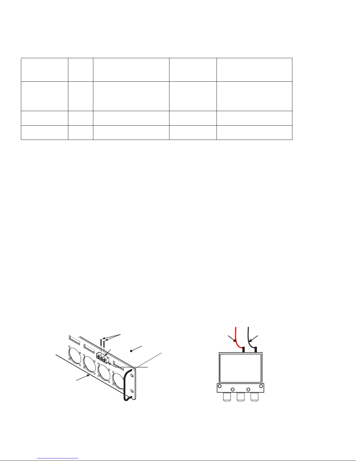
Table 1 (Continued)
S46 relay kits
Relay kit
model number
(Description)
S46-SPDT-KIT-40
(40GHz SPDT)
Relay
location
Kit parts summary
(Quantity)
Keithley part
number
Installation reference
1 to 8 4-40 ×5/8 PPH screws (2) 4-40X5/8PPH “18, 26.5, and 40GHZ Relay 1-8
SPDT relay (1) 21409
installation” on page 2
SPDT bracket (1) SYS46-314A
Connecting cable (1) SYS46-311C
S46-SP4T-KIT-40
(40GHz SP4T)
S46-SP6T-KIT-40
(40GHz SP6T)
A to D SP4T relay (1) S40-0013 “18GHz, 26.5 and 40GHz Relay
Ribbon cable (1) S46-U100-350A
A-D installation” on page 3
A to D SP6T relay (1) S40-0166 “18GHz, 26.5 and 40GHz Relay
Ribbon cable (1) S46-U100-350A
A-D installation” on page 3
Installation
Before installing the relays, remove the screws that secure the S46 top cover, and then remove the cover.
WAR NI NG : Disconnect the line cord and all cables from the S46 before removing the t op
cover.
To find the applicable installation procedure for your specific kit, refe r to the Installation refer ence column contained
in Table 1, and then perform the installation.
18, 26.5, and 40GHZ Relay 1-8 installation
1. Remove the nuts securing the cover plate over the mounting hole where the new relay is to be installed (see
Figure 1).
2. Install the support SPDT bracket at the relay location securing it with two nuts.
3. Thread the red and black wires (fr om the relay) th rough the PVC Tubing (TX-52-7)(not shown—part of connecting cable SYS46-311C). The TX-52-7 may be cut to a length that will allow the relay assembly to be
removed without removing the top cover.
4. Referring to Figure 1, solder the two control wires to the terminals of the relay.
5. Install the relay on the support bracket using the supplied 4-40X5/8PPH screws.
6. Plug the wire connector into the appropriate circuit board connector (see Figure 2).
7. Install the top cover, and then configure the system as covered in “System configuration” on page 3 of this
guide.
Figure 1
RELAY 1-8 installation
Relay
S46 Front Panel
PA-910 Rev. B / 12-05 2
4-40X5/8PPH Screws
Top Cover
SPDT Bracket
Red Wire
Top view of SPDT Relay
NO C NC
Black Wire
(+) ()
Page 3

Figure 2
Relay connector locations
RC
J7
RB
J6
RA
J5
To Power
Supply Board
R1
J18
RD
J8
RELAY AD
Connectors
(J5J8)
Relay
1
2
3
4
5
R8
J28
6
7
8
RELAY 18
Connectors
(J18J25)
Relay
A
B
C
D
Connector
J18
J19
J20
J21
J22
J23
J24
J25
Connector
J5
J6
J7
J8
18GHz, 26.5 and 40GHz Relay A-D installation
NOTE: Install 26.5 and 40GHz SP6T with port 6 at 12 o’clock position. Control wiring
changes port orientation—dimple identifies operational port 2.
1. Remove the four screws securing the cover plate over the mounting hole where the new relay is to
be installed (see Figure 3).
2. Connect the supplied ribbon cable to the relay (see Figure 3):
For 18GHz relays—Connect the supplied ribbon cable to the relay securing it with the two 440X1/4PPHSEM screws.
For 26.5 and 40GHz relays—Solder the supplied ribbon cable to the relay control solder pins.
3. Insert the relay in the mounting hole, and then secure it with the four scr ew s rem o ve d in ste p 1.
4. Plug the ribbon connector into the appropriate circuit board connector (see Figure 2).
5. Install the top cover, and then configure the system as covered in “System configuration” on page 3
of this guide.
System configuration
After installing the new relays, you must program the S46 for the new relay configuration with the following
command:
:ROUT:CONF:CPOL <clist>
<clist> is defined as follows:
clist = (@0 | 3-6, 0 | 3-6, 0 | 3-6, 0 | 3-6, 0 | 1, ... 0 | 1)
Relay: A B C D 1 ... 8
NOTE: All switch locations must be included in the <clist> whether or not all locations
are populated. The numeric value (1 or 3-6) indicates the number of throws,
while a value of 0 indicates that a location is not populated.
For example, if RELAY A and RELAY B are SP6T, RELAY 1 and RELAY 2 are
SPDTs, and all other locations are not populated, the command syntax would
be:
:ROUT:CONF:CPOL (@6,6,0,0,1,1,0,0,0,0,0,0)
See Section 3 of the S46 Instruction Manual (document number S46-901-01) for detailed programming
information.
3 PA-910 Rev. B / 12-05
Page 4

Figure 3
18, 26.5, and 40GHz Relay A-D installation
Relay Front Panel
Cover plate
S46 Front Panel
6
1
2
Relay
4-40X1/4PPHSEM
Screws (2 places)
Ribbon connector
4
3
Cover plate
SP4T
C
1
2
SP6T
1
6
C
5
4
S46 Front Panel
2
3
18 GHz Relay
26.5 and 40GHz Relay
White (-4)
Orange (-1)
SP4T
-3
-4
-2
-1
+C
S46-U100-350
Control cable
Control Wire Connections
Violet (-3)
Green (-2)
Brown (+28V)
6
1
2
Relay
Yellow (-6)
Orange (-1)
Green (-2)
Solder wire end to relay
connections
SP6T
-4
-5
-6
-3
-1
+C
S46-U100-350
Control cable
Red (-5)
White (-4)
Violet (-3)
-2
Brown (+28V)
PA-910 Rev. B / 12-05 4
 Loading...