

Page 1

www.keithley.com
A GREATER MEASURE OF CONFIDENCE
S46/S46T/S46L Microwave Switch System
Instruction Manual
S46-901-01 Rev. F / March 2011
Page 2

S46/S46T/S46L Microwave Switch System
Instruction Manual
©2001-2011, Keithley Instruments, Inc.
All rights reserved.
Cleveland, Ohio, U.S.A.
Document number: S46-901-01 Rev. F / March 2011
All Keithley Instruments product names are trademarks or registered trademarks of Ke ithley Instruments, Inc.
Other brand names are trademarks or registered trademarks of their respective holders
Page 3

Safety Precautions
The following safety precautions should be observed before using this product an d any associated instrumentation. Although some
instruments and accessories would normally be used with nonhazardous voltages, there are situations where hazardous conditions may
be present.
This product is intended for use by qualified personnel who recognize shock hazards and are familiar with the safety precautions required
to avoid possible injury. Read and follow all installation, operation, and maintenance information carefully before using the product. Refer
to the user documentation for complete product specifications.
If the product is used in a manner not specified, the protection provided by the product warranty may be impaired.
The types of product users are:
Responsible body is the individual or group responsible for the use and maintenance of equipment, for ensuring that the equipment is
operated within its specifications and operating limits, and for ensuring that operators are adequately trained.
Operators use the product for its intended function. They must be trained in electrical safety procedures and proper use of the instrument.
They must be protected from electric shock and contact with hazardous live circuits.
Maintenance personnel perform routine procedures on the product to keep it operating properly, for example, setting the line voltage or
replacing consumable materials. Maintenance procedures are described in the user documentation. The procedures explicitly state if the
operator may perform them. Otherwise, they should be performed only by service personnel.
Service personnel are trained to work on live circuits, perform safe installations, and repair products. Only properly trained service
personnel may perform installation and service procedures.
Keithley Instruments products are designed for use with electrical signals that are rate d Measurement Category I and Measurement
Category II, as described in the International Electrotechnical Commission (IEC) Standard IEC 60664. Most measurement, control, and
data I/O signals are Measurement Category I and must not be directly connected to mains voltage or to voltage sources with high transient
over-voltages. Measurement Category II connections require protection for high transient over-voltages often associated with local AC
mains connections. Assume all measurement, control, and data I/O connections are for connection to Category I sources unless otherwise
marked or described in the user documentation.
Exercise extreme caution when a shock hazard is present. Lethal voltage may be present on cable connector jacks or test fixtures. The
American National Standards Institute (ANSI) states that a shock hazard exists when voltage levels greater than 30 V RMS, 42.4 V peak,
or 60 V DC are present. A good safety practice is to expect that hazardous voltage is present in any unknown circuit before measuring.
Operators of this product must be protected from electric shock at all times. The responsible body must ensure that operators are
prevented access and/or insulated from every connection point. In some cases, connections must be exposed to potential human contact.
Product operators in these circumstances must be trained to protect themselves from the risk of electric shock. If the circuit is capable of
operating at or above 1000 V, no conductive part of the circuit may be exposed.
Do not connect switching cards directly to unlimited power circuits. They are intended to be used with impedance-limited sources. NEVER
connect switching cards directly to AC mains. When connecting sources to switching cards, install protective devices to limit f
and voltage to the card.
Before operating an instrument, ensure that the line cord is connected to a properly-grounded power receptacle. Inspect the connecting
cables, test leads, and jumpers for possible wear, cracks, or breaks before each use.
ault current
11/07
Page 4

When installing equipment where access to the main power cord is restricted, such as rack mounting, a separate main input power
!
disconnect device must be provided in close proximity to the equipment and within easy reach of the operator.
For maximum safety, do not touch the product, test cables, or any other instruments while power is applied to the circuit under test.
ALW AYS remove power from the entire test system and discharge any capacitors before: Connecting or disconnecting cables or jumpers,
installing or removing switching cards, or making internal changes, such as installing or removing jumpers.
Do not touch any object that could provide a current path to the common side of the circuit under test or power line (earth) ground. Always
make measurements with dry hands while standing on a dry, insulated surface capable of withstanding the voltage being measured.
The instrument and accessories must be used in accordance with its specifications and operating instructions, or the safety of the
equipment may be impaired.
Do not exceed the maximum signal levels of the instruments and accessories, as defined in the specifications and operating information,
and as shown on the instrument or test fixture panels, or switching card.
When fuses are used in a product, replace with the same type and rating for continued protection against fire hazard.
Chassis connections must only be used as shield connections for measuring circuits, NOT as safety earth ground connections.
If you are using a test fixture, keep the lid closed while power is applied to the device under test. Safe operation requires the use of a lid
interlock.
If a screw is present, connect it to safety earth ground using the wire recommended in the user documentation.
The symbol on an instrument means caution, risk of danger. The user should refer to the operating instructions located in the user
documentation in all cases where the symbol is marked on the instrument.
The symbol on an instrument means caution, risk of electric shock. Use standard safety precautions to avoid personal contact with
these voltages.
The symbol on an instrument shows that the surface may be hot. Avoid personal contact to prevent burns.
The symbol indicates a connection terminal to the equipment frame.
If this symbol is on a product, it indicates that mercury is present in the display lamp. Please note that the lamp must be properly
disposed of according to federal, state, and local laws.
The WARNING heading in the user documentation explains dangers that might result in personal injury or death. Always read the
associated information very carefully before performing the indicated procedure.
The CAUTION heading in the user documentation explains hazards that could damage the instrument. Such damage may invalidate the
warranty.
Instrumentation and accessories shall not be connected to humans.
Before performing any maintenance, disconnect the line cord and all test cables.
T o maintain protection from electric shock and fire, replacement components in mains circuits - including the power transformer, test leads,
and input jacks - must be purchased from Keithley Instruments. Standard fuses with applicable national safety approvals may be used if
the rating and type are the same. Other components that are not safety-related may be purchased from other suppliers as long as they
are equivalent to the original component (note that selected parts should be purchased only through Keithley Instruments to maintain
accuracy and functionality of the product). If you are unsure about the applicability of a replacement component, call a Keithley Instruments
office for information.
To clean an instrument, use a damp cloth or mild, water-based cleaner. Clean the exterior of the instrument only. Do not apply cleaner
directly to the instrument or allow liquids to enter or spill on the instrument. Products that consist of a circuit board with no case or chassis
(e.g., a data acquisition board for installation into a computer) should never require cleaning if handled according to instructions. If the
board becomes contaminated and operation is affected, the board should be returned to the factory for proper cleaning/servicing
.
Page 5

Table of Contents
Section Topic Page
1
General Information....................................................................... 1-1
Introduction................................................................................................. 1-1
Feature overview........................................................................................ 1-1
Manual addenda......................................................................................... 1-2
Specifications.............................................................................................. 1-2
Unpacking and inspection.................................... ... ... .... ... ... ... ... .... ... .......... 1-2
Inspection for damage.......................................................................... 1-2
Shipment contents ............................................................................... 1-2
Repacking for shipment ...................................... .... ... .......................... 1-2
Available accessories................................................................................. 1-2
SMA cables and torque wrench ........................................................... 1-3
Relay kits.............................................................................................. 1-3
Replacement relays ...................................... ... ... .... ... ... ....................... 1-4
Connections................................................................................................ 1-4
Installation................................................................................................... 1-5
Rack mounting.............................................................. ... ... .... ............. 1-5
Foot mounting...................................................................................... 1-6
2 Connections.................................................................................... 2-1
Introduction................................................................................................. 2-1
Handling precautions.................................................................................. 2-1
System configuration.............. ... ... ... .... ... ... ... .............................................. 2-1
Layout .................................................................................................. 2-1
Simplified schematic ............................................................................ 2-3
Connections................................................................................................ 2-4
Signal connections............................................................................... 2-6
GPIB control connection ...................................................................... 2-6
Power connections............................................................................... 2-8
Ground connection........................................................... ... .... ... ... ... .. 2-11
Switching considerations.......................................................................... 2-11
Connector integrity........................ ... ... ... .... ... ... .................................. 2-11
Voltage standing wave ratio ............................................................... 2-12
Path isolation...................................................................................... 2-12
Insertion loss...................................................................................... 2-12
RFI/EMI.............................................................................................. 2-12
3 Operation ........................................................................................ 3-1
Introduction................................................................................................. 3-1
Signal considerations ................................................................................. 3-1
Bus operation (GPIB) ................................................................................. 3-1
Bus connections................................................................................... 3-2
Primary address................................................................................... 3-2
Programming syntax............................................................................ 3-2
Response messages............................................................................ 3-5
GPIB commands ........................................................................................ 3-6
ROUTe commands............................................................................... 3-6
STATus commands .............................................................................. 3-9
SYSTem commands........................................................................... 3-11
Status model............................................................................................. 3-12
Page 6

Table of Contents S46/S46T/S46L Microwave Switch System Instruction Manual
Event register sets.............................................................................. 3-13
Enable registers............................................................ ... ... .... ... ......... 3-14
Queues............................................................................................... 3-14
Status byte and SRQ.......................................................................... 3-16
Service Request Enable Register....................................................... 3-18
Serial polling and SRQ ....................................................................... 3-18
Clearing registers and queues .................................................................. 3-18
Programming enable registers.................................................................. 3-19
Reading registers................................................................................ 3-20
Common commands................................................................................. 3-20
Errors ........................................................................................................ 3-26
4 Service Information ........................................................................4-1
Introduction ................................................................................................. 4-1
Handling and cleaning precautions..............................................................4-1
Handling precautions............................................................................ 4-1
Circuit board and connector cleaning ....................................................4-1
Coaxial switch performance verification...................................................... 4-2
Environmental conditions...................................................................... 4-2
Recommended equipment.................................................................... 4-2
Channel resistance tests ........................................ ... ... ... ... .... .............. 4-2
RF performance verification.................................................................. 4-3
Replacing components.............. ... ... .... ... ... ... .... ... ... ... .... ... ... ... ......................4-4
Replacing relays........................................................................ ... ........ 4-4
Mainframe replacement parts............................................................... 4-6
Replacement precautions..................................................................... 4-6
Soldering considerations ........................................ .............................. 4-6
Disassembly ..........................................................................................4-6
Ordering information ....................................................................................4-9
Factory service............................................. .... ........................................... 4-9
Index .................................................................................................. Index-1
ii Document number: S46-901-01 Rev. F / March 2011
Page 7

Introduction
This section contains general information about the S46/S46T/S46L Microwave Switch System.
The information is organized as follows:
WARNING If the equipment is not used as recommended by the manufactur er ,
If you have any questions after reviewing this information, please cont act your local Keithley
Instruments representative or call Keithley Instrume nts corp orate headqu arters (toll- free inside the
U.S. and Canada only) at 1-888-KEITHLEY (1-888-534-8453), or from outside the U.S. at
+1-440-248-0400. For worldwide contact numbers, visit the Keithley Instruments website at
www.keithley.com
• Feature overview
• Manual addenda
• Unpacking and inspection
• Available accessories
• Connections
• Installation
the overall safety will be impaired.
.
Section 1
General Information
Feature overview
The System 46 (S46) is an IEEE-488 bus controlled 19-inch rack-mounted RF relay switch
controller instrument. The standard S46 configurations can accommodate eight SPDT
unterminated coaxial microwave relays and four multi-pole, unterminated, coaxial microwave
relays. Any of these multi-pole unterminated relays can be one of the following relay types: SP4T
or SP6T.
S46 switching systems can be used as multiplexers, matrices, independent relays, or a
combination of configurations. Additional features of the S46 are as follows:
• Can be populated with up to eight 2-pole RF relays and a maximum of four , 4- pole, or 6-pole
RF relays
• LED indicators for error, power, and relay status
• Operating range to 40 GHz (relay dependent)
The System 46T (S46T) is also an IEEE-488 bus controlled 19-inch rack-mounted RF relay switch
controller instrument. In addition to the unterminated configurations that the S46 provides, the
S46T also has provisions to accommodate four terminated multi-pole, coaxial microwave relays,
or up to four transfer switches (DPDT) as well, with frequency ranges up to 26.5 GHz.
The System 46L (S46L) is also an IEEE-488 bus controlled 19-inch rack-mounted RF relay switch
controller instrument. The S46L only supports terminated relays in order to achieve 10 m cycle
closures. It can support up to four SP6T and four SPDT terminated relays.
Page 8

Section 1: General Information S46/S46T/S46L Microwave Switch System Instruction Manual
Manual addenda
Any improvements or changes concerning the S46/S46T/S46L Microwave Switch System will be
explained in an addendum included with the user documentation. Be sure to note these changes
and incorporate them into the documentation.
Specifications
Check the Keithley Instruments website (www.keithley.com/support) for latest version of the
product specifications.
Unpacking and inspection
Inspection for damage
The S46/S46T/S46L was carefully inspected electrically and mechanically before shipment. After
unpacking all items from the shipping carton, check for any obvio us signs of physical dam age that
may have occurred during transit. Report any damage to the shippin g agent immediately. Save the
original packing carton for possible future shipment.
Shipment contents
The following items are included with every S46/S46T/S46L order:
• S46/S46T/S46L Microwave Switch System (includes power cord)
• Product Information CD-ROM (part number S46-950-01), which inclu des the S46/S46T/
S46L Microwave Switch System Instruction Manual (part number S46H-901-01) and other
product-related information
• Installation instructions (part number P A-778, PA-910, P A- 913, or P A-1031) for the relay kits
(see Relay kits
• Additional accessories as ordered
Repacking for shipment
Should it become necessary to return the S46/S46T/S46L for repair, carefully pack the instrument
in its original packing carton or the equivalent, and follow these instructions:
• Call the Repair Department at 1-800-552-1115 for a Return Material Authorization (RMA)
number.
• Advise as to the warranty status of the S46/S46T/S46L.
• Write ATTENTION REPAIR DEPARTMENT and the RMA number on the shipping label.
Available accessories
)
NOTE Check the Keithley Instruments website (www.keithley.com) for additional
accessories that may have been added to the Keithley product line for the S4 6/
S46T/S46L.
1-2 Document number: S46-901-01 Rev. F / March 2011
Page 9

S46/S46T/S46L Microwave Switch System Instruction Manual Section 1: General Information
SMA cables and torque wrench
• S46-SMA-0.5: DC-18 GHz, low loss, semi-flex SMA-to-SMA cable assembly, 0.152 m
(6 in.) in length
• S46-SMA-1: DC-18 GHz, low loss, semi-flex SMA-to-SMA cable assembly, 0.30 5 m (12 in.)
in length
• S46-SMA-1.7: DC-18 GHz, low loss, semi-flex SMA-SMA cable assembly, 0.518 m
(20.4 in.)
• S46-SMA26-0.5: DC-26.5 GHz, low loss, semi-flex SMA-SMA cable assembly, 0.152 m
(6 in.)
• S46-SMA26-1: DC-26.5 GHz, low loss, semi-flex SMA-SMA cable assembly, 0.305 m
(12 in.)
• S46-SMA26-1.7: DC-26.5 GHz, low loss, semi-flex SMA-SMA cable assembly, 0.518 m
(20.4 in.)
• S46-TW: SMA cable torque wrench
Relay kits
Relays can be added to your test system by ordering relay kits from Keithley. Each kit includes a
relay, a cable assembly, any necessary hardware, and installation instructions. The installation
instructions are are also provided on the CD-ROM that is supplied with the S46/S46T/S46L.
S46 switch kits
• S46-SPDT-KIT: Standard-performance 18 GHz unterminated SPDT relay and cont ro l cab le
assembly
• S46-SP4T-KIT: Standar d-performance 18 GHz unterminated SP4T relay and control cable
assembly
• S46-SP6T-KIT: Standar d-performance 18 GHz unterminated SP6T relay and control cable
assembly
• S46-SPDT-KIT-R: High-performance 18 GHz unterminated SPDT relay and control cable
assembly
• S46-SP4T-KIT-R: High-performance 18 GHz unterminated SP4T relay and control cable
assembly
• S46-SP6T-KIT-R: High-performance 18 GHz unterminated SP6T relay and control cable
assembly
• S46-SPDT-KIT-26: High-performance 26.5 GHz unterminated SPDT relay and control cable
assembly
• S46-SP4T-KIT-26: High-performance 26.5 GHz unterminated SP4T relay and control cable
assembly
• S46-SP6T-KIT-26: High-performance 26.5 GHz unterminated SP6T relay and control cable
assembly
• S46-SPDT-KIT-40: High-performance 40 GHz unterminated SPDT relay and control cable
assembly
• S46-SP4T-KIT-40: High-performance 40 GHz unterminated SP4T relay and control cable
assembly
• S46-SP6T-KIT-40: High-performance 40 GHz unterminated SP6T relay and control cable
assembly
S46T switch kits
• S46T-SPDT-KIT-26: High-performance 26.5 GHz unterminated SPDT relay, spacer block,
and control cable assembly
Document number: S46-901-01 Rev. F / March 2011 1-3
Page 10

Section 1: General Information S46/S46T/S46L Microwave Switch System Instruction Manual
• S46T-SPDT-KIT-26T: High-performance 26.5 GHz terminated SPDT relay and control cable
assembly
• S46T-SP4T-KIT-26: High-performance 26.5 GHz unterminated SP4T relay, mounting plate,
and control cable assembly
• S46T-SP4T-KIT-26T: High-performance 26.5 GHz terminated SP4T relay and control cable
assembly
• S46T-SP6T-KIT-26: High-performance 26.5 GHz unterminated SP6T relay, mounting plate,
and control cable assembly,
• S46T-SP6T-KIT-26T: High-performance 26.5 GHz terminated SP6T relay and control cable
assembly
• S46T-SPDT-KIT: 18 GHz unterminated SPDT relay, spacer block, and control cable
assembly
• S46T-SPDT-KIT-T: 18 GHz terminated SPDT relay and control cable assembly
• S46T-MSPDT-KIT: Quantity 2, 18 GHz unterminated SPDT relays, mounting plate, and
control cable assembly (Note: Kit applicable only for relay A-D mounting locations)
• S46T-MSPDT- KIT-26: Quantity 2, 26 GHz unterminated SPDT relays, mounting plate, and
control cable assembly (Note: Kit applicable only for relay A-D mounting locations)
• S46T-SP4T-KIT: 18 GHz unterminated SP4T relay, mounting plate, and control cable
assembly
• S46T-SP4T-KIT-T: 18 GHz terminated SP4T relay and control cable assembly
• S46T-SP6T-KIT: 18 GHz unterminated SP6T relay, mounting plate, and control cable
assembly
• S46T-SP6T-KIT-T: 18 GHz terminated SP6T relay and control cable assembly
• S46T-XFER-KIT: 18 GHz transfer switch, mounting plate, and control cable assembly
• S46T-XFER-KIT-26: 26.5 GHz transfer switch, mounting plate, and control cable assembly
S46L switch kits
Replacement relays
NOTE The procedures for Replacing relays are provided in Section 4.
Defective relays can be replaced by ordering the appropriate relay kit.
Connections
Available S46/S46T/S46L connections include:
• S46L-SPDT-KIT-L: High-performance 20 GHz terminated SPDT relay, spacer block, and
control cable assembly
• S46L-SP6T-KIT-T: High-performance 18 GHz terminated SP6T relay and control cable
assembly
• Female SMA coaxial connectors for all front-panel input and output connections
• Power receptacle: Standard three-prong AC line connector on rear panel
• GPIB port (IEEE-488 connector) on rear panel
1-4 Document number: S46-901-01 Rev. F / March 2011
Page 11
S46/S46T/S46L Microwave Switch System Instruction Manual Section 1: General Information
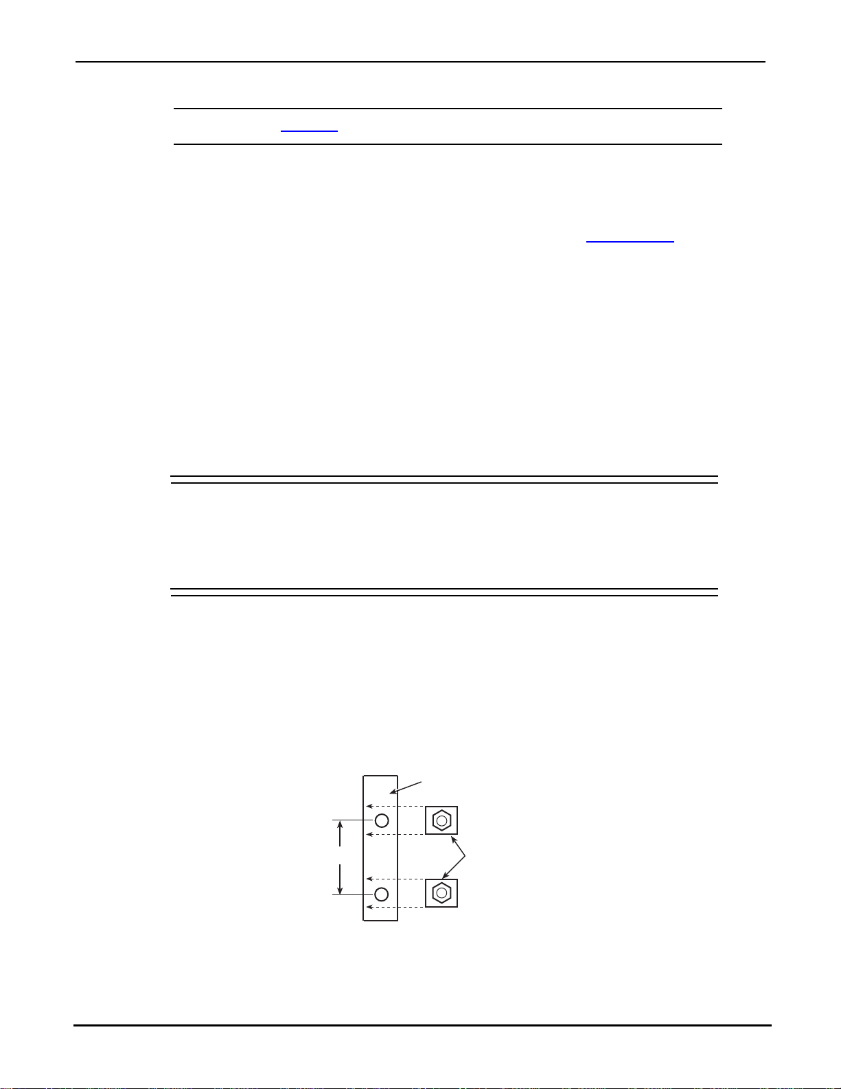
1.75”
Left Front
Rack Rail
Retaining
Clips with
Nuts
NOTE Refer to Section 2 for detailed connection information.
Installation
You can either mount the S46/S46T/S46L in a rack using the supplied ra ck-mounting har dware, or
operate it on a bench by installing the supplied feet, as described in Foot mounting
Rack mounting
The S46/S46T/S46L can be mounted in a standard 19-inch rack. The hardware necessary to
install the instrument in a rack is supplied with the S46/S46T/S46L.
Rack-mount kit
The S46/S46T/S46L is supplied with a Model 4288-7 rack-mount kit, which mounts the instrument
in a standard 19-inch rack. This kit includes rear brackets to provide additional support for the
instrument.
.
Rack-mount procedure
WARNING Make sure the S46/S46T/S46L is turned off, the line cord is
disconnected, and it is not connected to any external circuitry.
The power supply cord must be used as the mains disconnecting
device. The plug should be located in close proximity to the user
and remain readily accessible at all times.
To install the S46/S46T/S46L in the rack:
1. Select a location in the rack. The instrument fills 3.5 inches of vertical space.
2. Using Figure 1-1 as a guide, install two retaining clips on the left front rail. Slide each
retaining clip over a mounting hole so that the captive nut is positioned on the inside of the
rack cabinet. Install two retaining clips on the right front rail using the same procedure.
Figure 1-1
Rack preparation
Document number: S46-901-01 Rev. F / March 2011 1-5
3. If installed, remove the four feet from the bottom of the S46/S46T/S46L. Retain these feet
for future use.
4. Position the S46/S46T/S46L in the rack, and loosely attach the front panel to the rack rails
using the four supplied dress screws.
Page 12

Section 1: General Information S46/S46T/S46L Microwave Switch System Instruction Manual
5. Tighten the four dress screws.
6. Install and secure the rear brackets as described in the instructions supplied with the
rack-mount kit.
CAUTION Installation of the rear brackets is recommended to properly support the
S46/S46T/S46L.
Foot mounting
To operate the S46/S46T/S46L on a bench, attach the supplied rubber feet to the bottom of the
instrument. Each foot can be attached by removing the adhesive covering, and then pressing the
foot into place in a suitable location near each corner on the bottom case cover. These feet should
be removed before rack-mounting the instrument (see Rack mounting
).
1-6 Document number: S46-901-01 Rev. F / March 2011
Page 13

Introduction
This section contains information about overall switch system configuration and connections and
is organized as follows:
WARNING The procedures in this section are intended only for qualified
Section 2
Connections
• Handling precautions
• System configuration
• Connections
• Switching considerations
service personnel. Do not perform these procedures unless you
are qualified to do so. Failure to recognize and observe normal
safety precautions could result in personal injury or death.
Handling precautions
To maintain high-impedance isolation, be careful when handling the S46/S46T/S46L to avoid
contamination from foreign materials such as body oils. Such contamination can reduce isolation
resistance. To avoid possible contamination:
• Do not touch connector insulators.
• Operate the switch controller in a clean environment. If the instrument becomes
contaminated, it should be thoroughly cleaned as explained in Circuit board and connector
cleaning in Section 4.
System configuration
Layout
The S46, S46T, and S46L front panels are separately illustrated in Figure 2-1, and Figure 2-2
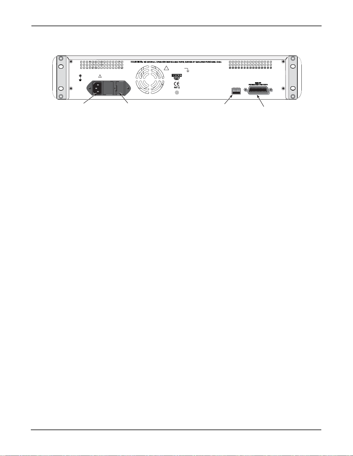
shows the rear panel for all three models.
All systems feature:
Connectors:
• Relay input and output connectors (see front panel)
• Power line receptacle (see rear panel)
• GPIB Control: IEEE-488 interface connector (see rear panel)
Page 14
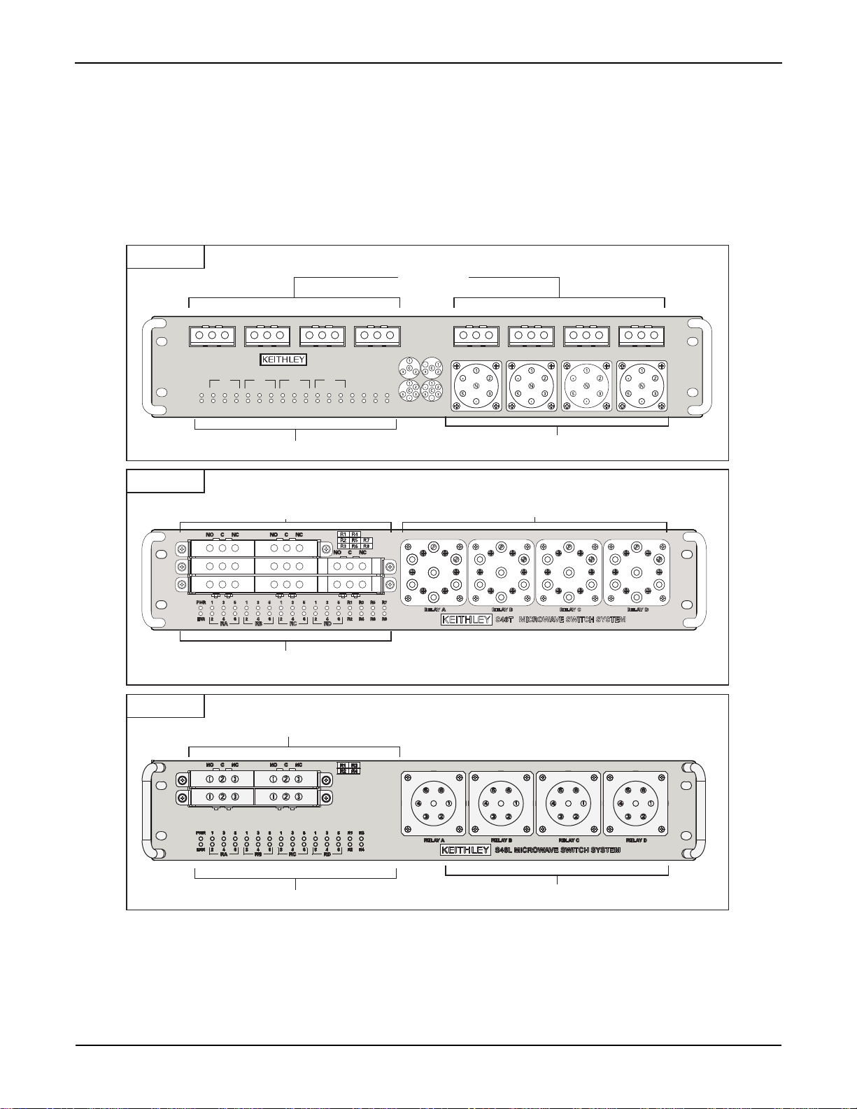
Status LEDs
2-pole relay
connections
Status LEDs
4-pole, 6-pole, XFER, or MSPDT
relay connections
2-pole relay
connections
SP4T
SP3T
SP5T
SP6T
S46 MICROWAVE SWITCH SYSTEM
PWR 1 3 5 1 3 5 1 3 5 1 3 5 R1 R3 R5 R7
ERR2 46 24 6246 24 6R2R4R6R8
RA RB RC RD
RELAY 1 RELAY 2 RELAY 3 RELAY 4
NO C NC NO C NC NO C NC NO C NC
RELAY 5 RELAY 6 RELAY 7 RELAY 8
NO C NC NO C NC NO C NC NO C NC
RELAY A RELAY B RELAY C RELAY D
4-pole or 6-pole relay connections
System 46T
System 46
NO C NC
NO C NC
NO C NC
NO C NC
NO C NC
NO C NC
NO C NC
NO C NC
NO C NCNO C NCNO C NCNO C NC NO C NC NO C NC NO C NC NO C NC
Status LEDs
2-pole relay
connections
4-pole or 6-pole relay connections
System 46L
Section 2: Connections S46/S46T/S46L Microwave Switch System Instruction Manual
Indicators (see front panel):
• Relay state LEDs (one for each relay)
• Power LED
• ERR LED (communication error or failed power on self-test)
Figure 2-1
S46/S46T/S46L front panels
2-2 Document number: S46-901-01 Rev. F / March 2011
Page 15
S46/S46T/S46L Microwave Switch System Instruction Manual Section 2: Connections
1 42 816
Primary Address
DIP Switch
IEEE-488
Connector
!
!
42V MAX.
ANY CONDUCTOR
CAUTION:
FOR CONTINUED PROTECTION AGAINST FIRE HAZARD, REPLACE FUSE WITH SAME TYPE AND RATING.
Line Fuse
Power Line
Receptacle
LINE FUSE
SLOWBLOW
1.6A, 250V
LINE RATING
100-240VAC
50, 60Hz
80VA MAX
Figure 2-2
Rear panel (all models)
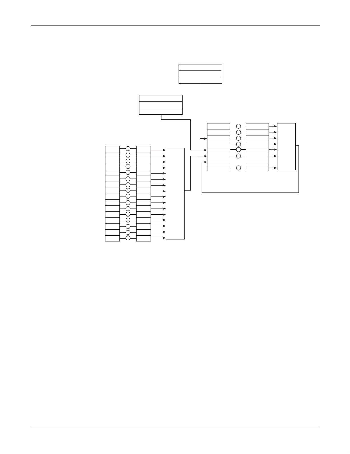
Simplified schematic
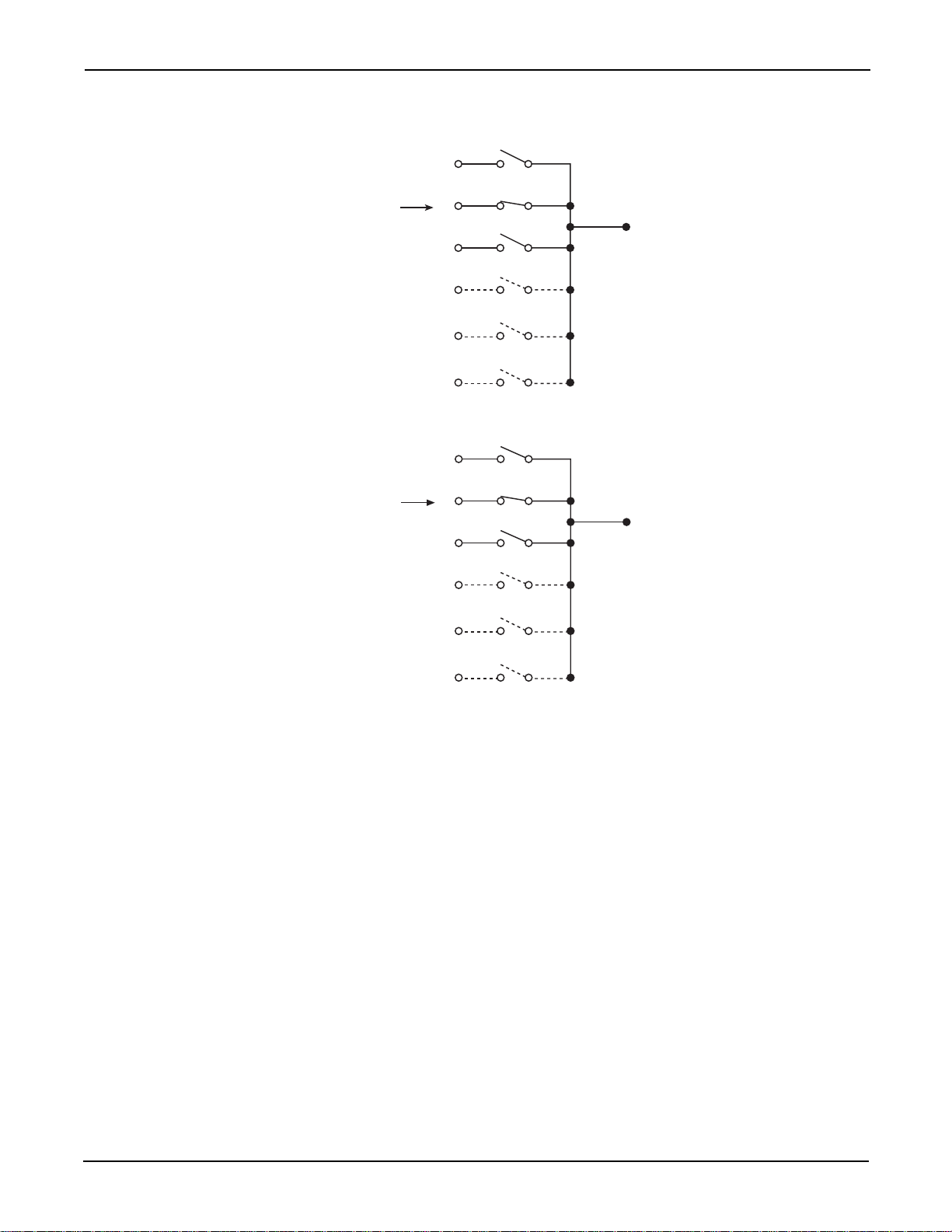
Figure 2-3 shows a simplified schematic diagram of the S46/S46T/S46L. Configuration is as
follows:
• RELAY 1 through RELAY 8 (for S46L, RELAY 1 through RELA Y 4) are 2-pole relays, each
with two inputs (normally closed and normally open) and one common.
• RELAY A through RELAY D on the S46 and S46T can be 4-pole, 6-pole, or MSPDT relays,
each with a maximum of six inputs and one common. The number of inputs depends on
relay configuration, as shown by the dotted lines in the diagram. The S46T can also
accommodate up to four transfer switches. The S46L only supports SP6T relays.
Document number: S46-901-01 Rev. F / March 2011 2-3
Page 16

Section 2: Connections S46/S46T/S46L Microwave Switch System Instruction Manual
RELAY A to RELAY D
4-pole or 6-pole
RELAY 1 to RELAY 8
2-pole
Normally
Closed
Normally
Open
Common
Connection
RELAY A to RELAY D
MSPDT switch
RELAY A to RELAY D
XFER switch
Normally
Closed
Normally
Open
Common
Connection
Normally
Closed
Normally
Open
Common
Connection
Top
Relay
Bottom
Relay
Input
Connections
2
3
4
5
6
1
Common
Connection
Input
Connections
2
1
()
(+)
Power
Terminals
Actuator
3
4
De-energized
Position
Energized
De-energized
RF Switching 13, 24
12, 34
Figure 2-3
Simplified schematic
Connections
Signal connections
RF input and output connections are made either to the RELAY 1 through RELAY 8 connectors, or
to the RELAY A through RELAY D connectors, as described below.
Unterminated SP4T, SP6T, XFER (26.5 GHz), and unterminated 40 GHz relays have female SMA
2.9 connectors. All others have female SMA connectors.
2-4 Document number: S46-901-01 Rev. F / March 2011
Page 17

S46/S46T/S46L Microwave Switch System Instruction Manual Section 2: Connections
Cables
Only use 50 Ω cables specified for operation at the system frequency (18 GHz, 26.5 GHz, or
40 GHz).
Relay configuration
The S46/S46T/S46L can be populated with relays as follows:
• RELAY A, B, C, and D can be populated with either 4-pole or 6-pole relays. The S46T can
also accommodate up to four transfer switches (DPDT), MSPDT, and untermin at ed SP4T
and SP6T relays. Make sure that you note the operational diffe rences in these relays (see
Section 3
• RELA Y 1 through RELAY 8 (RELAY 1 through RELAY 4 for S46L) are populated with 2-pole
RF relays.
• Any or all relay locations can be populated.
). The S46L only supports SP6T relays.
Channel assignments
Table 2-1 summarizes relay channel assignments. See Section 3 for information about controlling
channels.
NOTE Regardless of the pole configuration of RELAY A, RELAY B starts numbering at
channel 7.
Table 2-1
Relay channel assignments
Relay Channels
RELAY A 1 through 6
RELAY B 7 through 12
RELAY C 13 through 18
RELAY D 19 through 24
RELAY 1 to 8 25 through 32
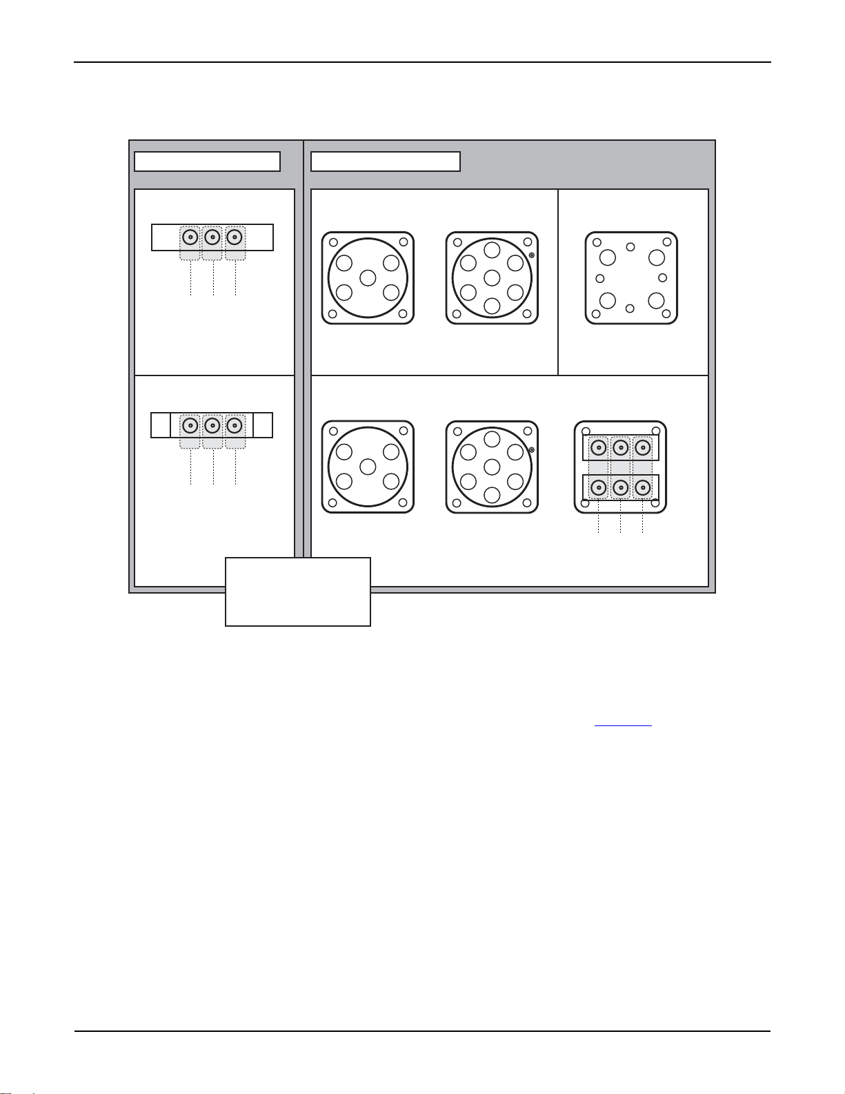
Input/output connections
Figure 2-4 shows input and output connections for both RELAY A through RELAY D and RELAY 1
through RELAY 8. RELAY A through RELAY B have up to six input connections and one output
connection (depending on relay pole configuration). RELAY 1 through RELAY 8 each have two
input connections and one output connection.
Document number: S46-901-01 Rev. F / March 2011 2-5
Page 18
Section 2: Connections S46/S46T/S46L Microwave Switch System Instruction Manual
RELAY 1 to 8 Connections RELAY A to D Connections
C = Common
1 to 4 = Inputs
C
2
6
5
3
4-pole
Terminated
1 to 4 = Inputs
1
3
2
4
XFER
Un-terminated
C = Common
1 to 6 = Inputs
6-pole
C
1
4
2
3
6
5
C = Common
1 to 4 = Inputs
C
1
4
3
2
4-pole
MSPDT
C = Common
1 to 6 = Inputs
6-pole
C
1
4
2
3
6
5
Terminated
Un-terminated
NCNO C
NCNO C
NCNO C
NC = Normally Closed
NO = Normally Open
C = Common
Figure 2-4
Relay input and output connections
T ransfer switch (XFER)
Up to four transfer switches (DPDT) can be located in Relay positions A through D. The transfer
switch cross-connects two input ports with two output ports. When using transfer switches, make
sure that you note the operational differences of these switches (see Section 3
GPIB control connection
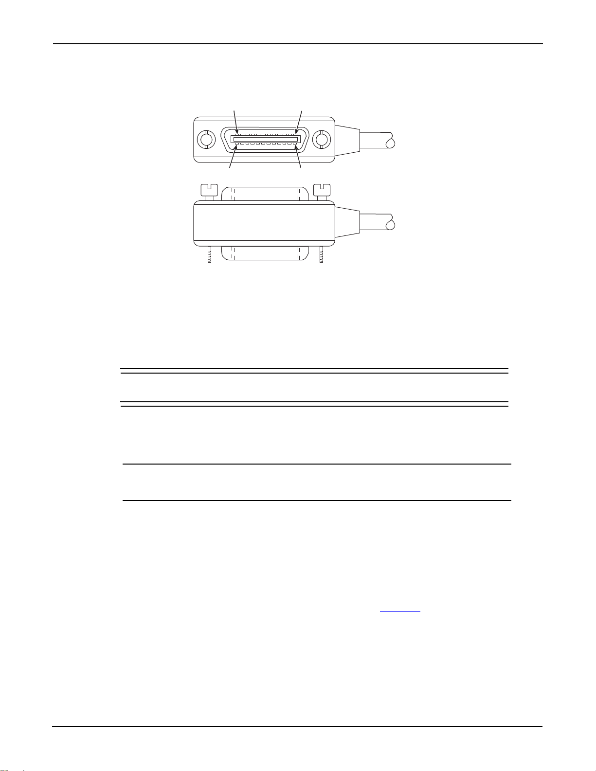
The rear-panel, IEEE-488 (GPIB) control port is connected to the GPIB port of a computer
(controller) using a shielded IEEE-488 interface cable with metric mating screws. Fi gure 2-5 shows
the GPIB control connector, and Table 2-2 summarizes the GPIB control connector terminals.
).
2-6 Document number: S46-901-01 Rev. F / March 2011
Page 19
S46/S46T/S46L Microwave Switch System Instruction Manual Section 2: Connections
1
12
13
24
Figure 2-5
GPIB control connector
Remember the following restrictions when attaching instruments to the GPIB:
• A maximum separation of 4 meters between any two instruments on the bus
• A maximum total cable length of 20 meters
• No more than 15 devices on the bus
• No two instruments can have the same address
If you cannot meet these requirements, the us e of bus extenders is recommended.
CAUTION IEEE-488 common is connected to digital common. Maximum voltage
between digital common and earth ground is 0 V.
Connectors may be stacked to allow a number of parallel connections to one instrument. Two
screws located on a standard connector maintain secure connections between connectors.
NOTE To minimize interference caused by electromagnetic radiation, use shielded
IEEE-488 cables such as the Keithley Model 7007.
To connect devices to the GPIB:
1. Line up the cable connector with the IEEE-488 connector located on the rear panel of the
S46/S46T/S46L. The connector’s design allows installation to the port in only one position.
2. Secure the connector by tightening the screws firmly (do not overtighten).
3. Add any additional connectors to the por t, as re qu ire d .
4. Connect the free end of the cable to the controller.
5. Confirm that the primary address is set properly (see Section 3
information).
for GPIB address
Document number: S46-901-01 Rev. F / March 2011 2-7
Page 20

Section 2: Connections S46/S46T/S46L Microwave Switch System Instruction Manual
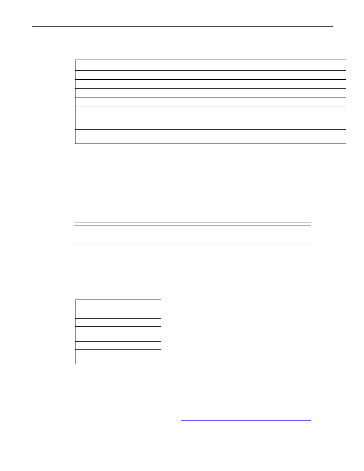
Table 2-2
GPIB control connector terminals
Contact number IEEE-488 designation Type
1DI01 Data
2DI02 Data
3DI03 Data
4DI04 Data
5 EOI (24)* Management
6 DAV Handshake
7 NRFD Handshake
8 NDAC Handshake
9 IFC Management
10 SRQ Management
11 ATN Management
12 SHIELD Ground
13 DI05 Data
14 DI06 Data
15 DI07 Data
16 DI08 Data
17 REN (24)* Management
18 Gnd (6)* Ground
19 Gnd (7)* Ground
20 Gnd (8)* Ground
21 Gnd 9)* Ground
22 Gnd (10)* Ground
23 Gnd (11)* Ground
24 Gnd, LOGIC Ground
* Numbers in parentheses refer to signal ground return of referenced
contact number. EOI and REN signal lines return on contact 24.
GPIB primary address
On the rear panel, there are five GPIB DIP switches to set the GPIB primary address. The GPIB
address is set to 7 at the factory . Refer to Section 3
of this manual for information about setting the
primary address.
Power connections
Line voltage
The S46/S46T/S46L operates from a line voltage in the range of 100 V to 240 V at a frequency of
50 Hz or 60 Hz. Line voltage selection is automatic.
CAUTION Operating the S46/S46T/S46L on an incorrect line voltage may cause
damage, possibly voiding the warranty.
2-8 Document number: S46-901-01 Rev. F / March 2011
Page 21

S46/S46T/S46L Microwave Switch System Instruction Manual Section 2: Connections
Line power connection
To connect the S46/S46T/S46L to line power:
1. Connect the female end of the supplied power cord to the AC receptacle on the rear pan el.
2. Connect the other end of the supplied power cord to a grounded AC outlet.
WARNING The power cord supplied with the S46/S46T/S46L contains a
separate ground for use with grounded outlets. An adequately
rated, CERTIFIED power supply cord with embedded plug suitable
for the earthed receptacle of the applicable country must be used.
Failure to use a grounded outlet may result in personal injury or
death due to electric shock.
Line fuse replacement
A rear-panel fuse protects the power line input of the S46/S46T/S46L. If the line fuse need to be
replacemed, perform the steps below.
WARNING Disconnect the line cord from the instrument before changing the
line fuse.
To replace the line fuse:
1. The fuse is located in a holder in the power module adjacent to the AC receptacle (see
Figure 2-2). At the right of the fuse holder is a small tab. At this location, use a small-bladed
screwdriver to release the fuse holder.
2. Slide the fuse holder out to gain access to the fuse carrier and fuse.
3. Remove the carrier with the damaged fuse, and replace the fuse with the correct type (listed
in Table 2-3).
WARNING For continued protection against fire or instrument damage,
replace the fuse only with a CERTIFIED part of the type and rating
listed. If the instrument repeatedly damages fuses, locate and
correct the cause of the problem before replacing the fuse.
Table 2-3
Line fuse
Line voltage Fuse rating Keithley part number
100 V to 240 V 1.6 A slow blow, 250 V, 5 mm x
20 mm
FU-106-1.6
4. Install the fuse carrier in the fuse holder, and then insert the fuse holder in the power
module.
Power supply fuse replacement
An internal fuse protects the output of the 28 V DC power supply of the S46/S46T/S46L. If the
in-line fuse needs to be replaced, perform the steps below.
Document number: S46-901-01 Rev. F / March 2011 2-9
Page 22

Section 2: Connections S46/S46T/S46L Microwave Switch System Instruction Manual
WARNING Disconnect the line cord from the instrument before removing the
top cover and replacing the power supply fuse.
To replace the line fuse:
1. Remove the screws that secure the top cover, and then remove the cover.
2. Locate the in-line fuse holder (see Figure 2-6).
3. Twist the fuse holder to open it, and then remove the fuse.
4. Replace the damaged fuse with one that has the fuse rating listed in Table 2-4.
5. Replace the top cover.
WARNING For continued protection against fire or instrument dama ge, replace the
fuse only with a CERTIFIED part of the type and rating listed. If the
instrument repeatedly damages fuses, locate and correct the cause of the
problem before replacing the fuse.
Table 2-4
Power supply fuse
Line voltage Fuse rating Keithley part number
100 V to 240 V 1.6 A slow blow, 250 V, 5 mm x
20 mm
FU-106-1.6
2-10 Document number: S46-901-01 Rev. F / March 2011
Page 23

S46/S46T/S46L Microwave Switch System Instruction Manual Section 2: Connections
Top cover
Digital board
Power
supply
Rear cover
Front
cover
Power supply fuse
(FU-106-1.6)
Figure 2-6
Power supply fuse
Ground connection
The rear-panel ground screw (Figure 2-2) should be connected to safety earth ground using #18
AWG or larger wire if the S46/S46T/S46L is not mounted in a properly grounded rack.
Switching considerations
Connector integrity
Document number: S46-901-01 Rev. F / March 2011 2-11
Signals switched by the S46/S46T/S46L may be subject to various ef fect s that can seriously af fect
their integrity. The following paragraphs discuss these effects and ways to minimize them.
CAUTION Do not close more than one RF p ath per multiport switch. Degradation of
RF performance will result, and the switch may be damaged.
As is the case with any high-resistance device, the integrity of connectors can be damaged if they
are not handled properly. If connector insulation becomes contaminated, the insulation resistance
will be substantially reduced, affecting high-impedance measurement paths. Refer to Section 4
cleaning information.
for
Page 24

Section 2: Connections S46/S46T/S46L Microwave Switch System Instruction Manual
Oils and salts from the skin can contaminate connector insulators, reducing thei r resi stance. Also,
contaminants present in the air can be deposited on the insulator surface. To avoid these
problems, never touch the connector insulating material. In addition, use the relay only in clean,
dry environments to avoid contamination.
V olt age standing wave ratio
The voltage standing wave ratio (VSWR) is a me asurement of mismatch in a cable , waveguide, or
antenna system. The measurement is shown as ratio to 1 (for example, a VSWR of 1.2 is actually
the ratio of 1.2:1). Refer to the specifications located on the Keithley Instrument s website
(www.keithley.com/support
) for S46/S46T/S46L VSWR information.
Path isolation
The path isolation is the equivalent impedance between any two test paths in a measurement
system. Ideally, the path isolation should be infinite, but the actual resistance and distributed
capacitance of cables and connectors results in less than infinite path isolation values for these
devices.
Path isolation resistance forms a signal path that is in p arallel with the equivalent resistance of the
device-under-test (DUT). For low-to-medium device resistance val ue s , path isolation resistance is
seldom a consideration; however, it can seriously degrade measurement accuracy when testing
high-impedance devices. The voltage measured across such a device, for example, can be
substantially attenuated by the voltage divider action of the device source resistance and path
isolation resistance. Also, leakage currents can be gen erated through these resist ances by volt age
sources in the system. Refer to the specifications located on the Keithley Instruments website
(www.keithley.com/support
) for S46/S46T/S46L isolation information.
Insertion loss
Insertion loss indicates signal lost while passing through the switch. This loss occurs in the various
signal path components through the switch conn ectors, computer boar d traces, and relay. Refer to
the specifications located on the Keithley Instruments website (www.keithley.com/support
S46T/S46L insertion loss information.
RFI/EMI
RFI (radio frequency interference) and EMI (electromagn etic interference) are gen eral terms used
to describe electromagnetic interference over a wide range of frequencies across the spectrum.
Such interference can be particularly troublesome at low signal levels, but it can also affect
measurements at high levels if the problem is of suf ficient severity.
EMI can be caused by steady-state sources such as radio or television broadcast signals, or some
types of electronic equipment (microprocessors, high-speed digital circuits, and so on.), or it can
result from impulse sources, as in the case of arcing in high-voltage environments. In either
situation, the effect on the desired signal can be considerable if enough of the unwanted signal is
present.
EMI can be minimized in several ways. The most obvious method is to keep the equipment and
signal leads as far away from the RFI source as possible. Shielding the switching switch, signal
leads, sources, and measuring instruments will often reduce RFI to an acceptable level. In
extreme cases, a specially constructed screen room may be required to sufficiently attenuate the
troublesome signal.
) for S46/
2-12 Document number: S46-901-01 Rev. F / March 2011
Page 25

Introduction
This section contains the following operating information for the S46/S46T/S46L:
• Signal considerations
• Bus operation (GPIB)
• GPIB commands
• Status model
• Clearing registers and queues
• Programming enable registers
• Common commands
• Errors
Signal considerations
Section 3
Operation
WARNING Maximum voltage between any conductor and ground is 42V.
CAUTION To prevent damage to the S46/S46T/S46L, do not exceed the maximum
signal level specifications of the switch.
Maximum signal level specifications
• Maximum voltage: 30 V DC, 42 V peak
• Maximum Power (per RF channel):
• 35 W CW at 18 GHz, 1 W switching; load VSWR of 1.20:1 maximum
• 10 W CW at 26.5 GHz, 1 W switching; load V SWR of 1.20:1 maximum
• 3 W CW at 40 GHz, 1W switching; load V SWR of 1.20:1 maximum
• Term in at i on pow er : 1 W per termination, 3 W total power per relay
CAUTION Do not close more than one RF path per multiport switch. Degradation of
RF performance will result and the switch may be damaged.
Bus operation (GPIB)
NOTE The term GPIB (general purpose interface bus) is used in this manual. GPIB is
simply another term for the IEEE-488 bus.
Page 26
Section 3: Operation S46/S46T/S46L Microwave Switch System Instruction Manual
ON
LSB
MSB
1
2
4
8
16
Decimal
Weight
0
0
4
0
16
20
GPIB Address
+
Decimal
Value
Note: There is no GPIB address of 31 (if
the switches are set to 31, they will
be interpreted as being set to 30).
00001
10000
Binary
Weight
01000
00100
00010
Bus connections
Before using the S46/S46T/S46L, you must connect the IEEE-488 connector on the rear panel of
the switch to the IEEE-488 connector of the controller. Use a Keithley Instruments Model 7007 or
similar shielded IEEE-488 cable for this connection. Refer to Section 2
for more information about
the IEEE-488 connection.
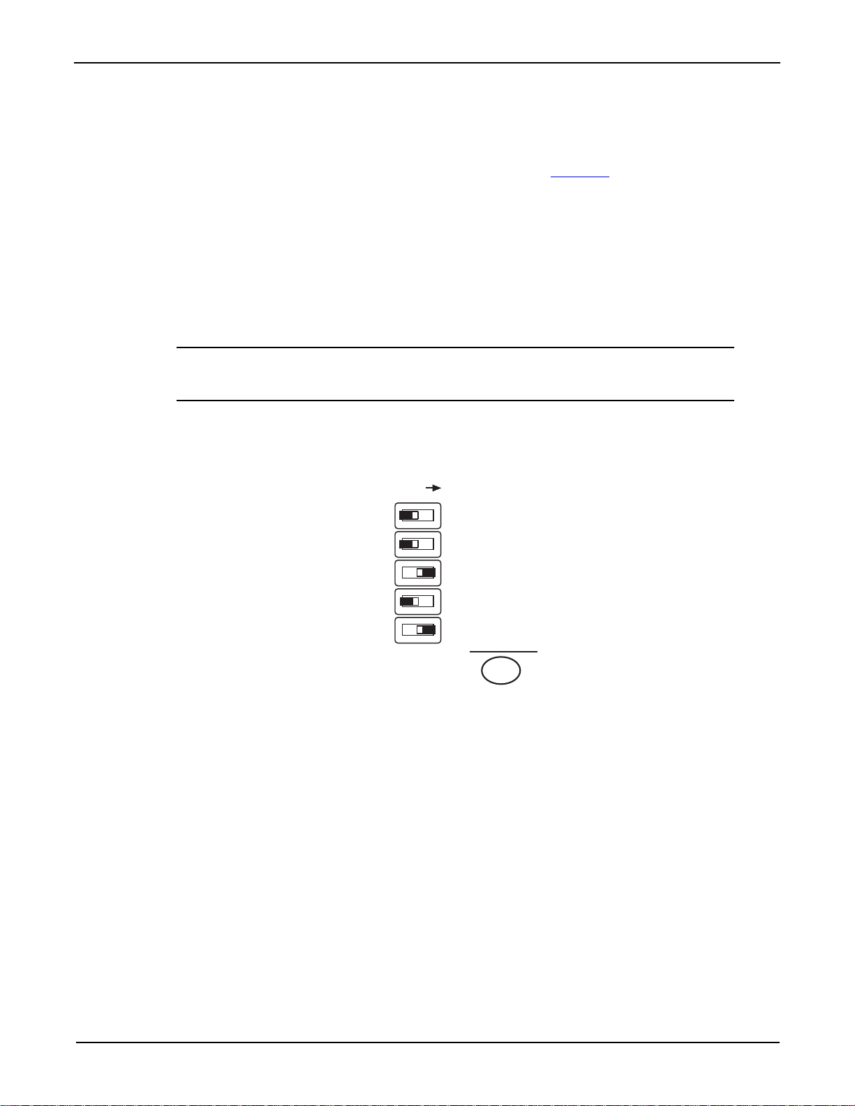
Primary address
The primary address of the S46/S46T/S46L must agree with the primary address you intend to
specify in the controller’s programming language. There are five GPIB address DIP switches
located on the rear panel adjacent to the IEEE-488 connector. The GPIB address is set to 7 at the
factory. As shown in Figure 3-7, these switches use a binary weighted configuration.
NOTE Momentarily remove power from the instrument after changing the address to
update the address to the new setting.
Figure 3-7
Primary address DIP switch example
Programming syntax
Syntax rules for programming the S46/S46T/S46L are described in the following paragraphs.
Commands and parameters
The general form for SCPI commands is demonstrated in Table 3-6 through Tabl e 3- 8. SCPI
commands are hierarchical in nature and begin with a root command. For example, to open all
channels for relays 1 and 2, send the following command:
:OPEN:ALL
The root path command for the above example is ROUTe. This is an optional command word (as
indicated by the brackets ([ ]) in the table) and need not be used.
The general form for common commands is shown in Table 3-8 and discussed later in this section.
3-2 Document number: S46-901-01 Rev. F / March 2011
Page 27

S46/S46T/S46L Microwave Switch System Instruction Manual Section 3: Operation
NOTE Each common command is preceded by a star (*).
Parameters provide specific types of information. The following list (Table 3-5) contains the
definitions of the different parameter types.
Table 3-5
Parameter types
Parameter Description
<name> Name parameter: Select a parameter name from a listed group.
<clist> List of channels. The following examples demonstrate proper format:
(@1,7) channels 1 and 7.
<b> Boolean: Enable (1 or on) or disable (0 or off) a function.
<NRf> Numeric representation format: Number can be expressed as an
integer, real number, or an exponent (for example, 2.3E6).
<n> Numeric value: An NRf number or one of the following name
parameters:
- DEFault: Uses the *RST default parameter value
- MINimum: Uses the lowest allowable parameter value
- MAXimum: Uses the largest allowable parameter value
Short-form commands
Most SCPI command words and name parameters have a shor t-form version. The short-form
versions are identified in the SCPI tables by the upper case characters. Example:
:ROUT:CLOS (@1,7) = :ROUTe:CLOSe (@1,7)
NOTE Command words and parameter names are not case-sensitive.
Query commands
Query commands request information (queries) and can be identified by the question mark
appearing after the command (?). Example:
:CLOSe? Queries the channels that are closed.
Command messages
Program message: A program message is made up of one or more command words sent by the
computer to the instrument. Some programming operations require several command words.
Single command message: This program message uses the command words required to
perform a single programming operation. Example:
:SYST:ERR? Reads the system error queue.
Multiple command message: This program message contains two or more command
operations. Each command string is separated by a semicolon (;). The following example uses the
short-form format to reduce the size of the message:
:ROUT:CLOS (@1,7);:ROUT:CLOS?
The above program message closes channels 1 and 7, and then queries for closed relays.
Document number: S46-901-01 Rev. F / March 2011 3-3
Page 28

Section 3: Operation S46/S46T/S46L Microwave Switch System Instruction Manual
:ROUT:CLOS (@2,8)
Root Path
Command
Channel Numbers
Example command
To con ne ct ch an n els 2 an d 8:
:ROUT:CLOS (@2,8);
Refer to Figure 3-8 for a diagram of the parts of this command and to Fi gure 3-9 for an illustration
of the physical connections.
Figure 3-8
Command diagram
In this example, commands to close channels 2 and 8 are sent, which closes inputs to both
RELAY A and RELAY B.
Program message terminator (PMT)
Each program message must be terminated with an LF (line feed), EOI (end or identify), or an
LF + EOI. The bus will stop responding if your computer does not provide this termination. The
following example shows how a program message must be terminated:
open:all <PMT>
3-4 Document number: S46-901-01 Rev. F / March 2011
Page 29
S46/S46T/S46L Microwave Switch System Instruction Manual Section 3: Operation
Channel 2
2
3
4
5
6
1
RELAY A
Channel 8
2
3
4
5
6
1
RELAY B
Figure 3-9
Controlling relay connections
Command execution rules
• Commands execute in the order presented in the program message.
• An invalid command generates an error and is not executed.
• Valid commands preceding an invalid command in a multiple command program message
• Valid commands following an invalid command in a multiple command program message
Response messages
A response message is the message sent by the instrument to the computer in response to a
query command program message.
Sending a response message
After sending a query command, the response message is placed in the output queue. When the
relay unit is then addressed to talk, the response message is sent from the output queue to the
computer.
are executed.
are ignored.
Document number: S46-901-01 Rev. F / March 2011 3-5
Page 30

Section 3: Operation S46/S46T/S46L Microwave Switch System Instruction Manual
Multiple response messages
If you send more than one query command in the same program message, the multiple response
messages for all the queries are sent to the computer when the re lay unit is addressed to t alk. The
responses are sent in the order the query com m an d s wer e se nt an d are separate d by
semicolons (;). Items within the same query are separated by commas (,). The following example
shows the response message for a program message that contains four single item query
commands:
0;1;1;0
Response message terminator (RMT)
Each response is terminated with an LF (line feed) and an EOI (end or identify). The following
example shows how a multiple response message is terminated:
0;l;l;0 <RMT>
Message exchange protocol
Two rules summarize the message exchange protocol:
Rule 1: You must always tell the S46/S46T/S46L what to send to the computer.
Perform the following two steps to send information from the instrument to the computer:
1. Send the appropriate query command(s) in a program message.
2. Address the S46/S46T/S46L to talk.
Rule 2: The computer must receive the complete response message before another program
message can be sent to the instrument.
GPIB commands
This section contains S46/S46T/S46L specific commands for the three different subsystems:
• ROUTe commands
• STATus commands
• SYSTem commands
ROUT e commands
A list of the ROUTe commands is contained in Table 3-6. ROUTe commands are used to open and
close channels, query closed channels, and to read and reset the relay closure count. The
brackets indicate that
Following the table are details defining the use of the specific
Table 3-6
:ROUTe subsystem command set
Commands Description
[:ROUTe]
:CLOSe <clist>
:CLOSe?
:COUNt?
:RCOunt <clist>
[:ROUTe] is optional and need not be included in the command message.
ROUTe subsystem commands.
Root path to :ROUTe subsystem commands.
Enter the list of channels to close.
Query which channels are closed. Returns a <clist> of cl osed channels.
Returns 32 (28 for the S46L) comma-separated variables representing the
closure count on each of the 32 (28 for the S46L) channels.
Resets (sets to zero) the closure count for channels specified in <clist>.
3-6 Document number: S46-901-01 Rev. F / March 2011
Page 31
S46/S46T/S46L Microwave Switch System Instruction Manual Section 3: Operation
Table 3-6
:ROUTe subsystem command set
Commands Description
:OPEN <clist>
:ALL
:CONFigure
:CPOLe <clist>
:CPOLe?
:SPARameterN <string>
:SPARameterN?
Enter the list of channels to open.
Opens all channels.
Path to configuration commands.
Define which relays are present in system.
Query which relays are present in system.
Stores s-par ameter string for channel N (N = 1 through 32 [28 for the
S46L]). Maximum 68 characters.
Returns stored s-parameter string for channel N (N = 1 through 32 [28 for
the S46L]) with no delimiters.
:CLOSe <clist> Close channels
:CLOSe? Query closed channels
Parameters <clist> = (@ chanlist)
Where chanlist is the list of channels to be closed separated by commas.
Description Enter the list of channels to close in a <clist>. For example, if you want to close
channels 2 and 7, send
ROUT:CLOS (@2,7). Tabl e 3- 7 summarizes channel
assignments.
CAUTION Do not close more than one RF path per multiport switch. Degradation of
RF performance will result and the switch may be damaged.
Query This query command is used to return a <clist> of presently closed channels. For
example, if channels 2 and 7 are closed and
will return
(@2,7).
ROUT:CLOS? is sent, then the query
Table 3-7
Relay channel assignments
Relay Channels
RELAY A 1 through 6
RELAY B 7 through 12
RELAY C 13 through 18
RELAY D 19 through 24
RELAY 1 to 8 25 through 32
RELAY 1 to 4 25 through 28
(S46L only)
:COUNt? Return closure count
Description This command (query only) is used to return 32 (28 for the S46L)
comma-separated values representing the closure count (the number of times the
channel has been closed). Unpopulated channels always have a count of zero.
To reset this count, see :RCOunt <clist>
Document number: S46-901-01 Rev. F / March 2011 3-7
Reset closure count for channels.
Page 32

Section 3: Operation S46/S46T/S46L Microwave Switch System Instruction Manual
:RCOunt <clist> Reset closure count for channels
Parameters <clist> = (@ chanlist)
Where chanlist is the list of channels to be reset.
Description This command is used to reset closure count in a <clist>. For example, to reset
the closure count values for channels 1 and 4, send:
:ROUT:CLOS:RCO (@1,4)
Query No query form of this command exists.
:OPEN <clist> Open channel(s)
Parameters <clist> = (@ chanlist)
Where chanlist is the list of channels to be opened.
Description Enter the list of channels to open in a <clist>. For example, if you want to open
channels 2 and 7, send:
:ROUT:OPEN (@2,7)
Query No query form of this command exists.
:OPEN:ALL Opens all channels
Description Use this command to open all channels simultaneously.
Query No query form of this command exists.
:CONfigure:CPOLe <clist> Define relays present in system
Parameters <clist> = (@ chanlist)
Where chanlist is the list of relay channels present in the system.
Description This command is used to define which relays are present in the system as a
<clist>. This command need be used only if the system is being configured
differently from the factory-shipped relay configuration.
<clist> is defined as follows (where
3 and 6):
clist = (@0|3-6, 0|3-6, 0 |3-6, 0|3-6, 0|1, ... 0|1)
A B C D 1...8
Note that all switch locations must be included in the <clist>. For example, if
RELAY A and RELAY B are SP6T, RELAY 1 and RELAY 2 are SPDTs, and all
others are not populated, the command syntax would be:
:ROUT:CONF:CPOL (@6,6,0,0,1,1,0,0,0,0,0,0) (for S46/S46T)
:ROUT:CONF:CPOL (@6,6,0,0,1,1,0,0) (for S46L)
Some S46T relays require values other than the number of throws.
S46T-MSPDT-KIT and S46T -XFER-KIT are programmed with a value of 3. The
MSPDT top relay uses the first channel assignment for relays A through D; the
second channel controls the lower relay. The XFER relay uses the first channel
assignment for relays A through D. Terminated SP4T relays are programmed with
a value of 6. Ports 2, 3, 5, and 6 control channels are used.
0|3-6 means enter a 0 or a number between
(
1...4 for S46L)
Query This query returns the relay configuration pole information with the form factor
defined above.
3-8 Document number: S46-901-01 Rev. F / March 2011
Page 33

S46/S46T/S46L Microwave Switch System Instruction Manual Section 3: Operation
:CONFigure:SP ARameterN <string> Define s-parameter string
Parameters <string> = ASCII string of up to 68 characters representing s-parameters enclosed
in single or double quotes (both quotes must be the same type).
Description This command allows you to store a string of up to 68 characters representing
s-parameters for channel
following command stores s-parameters for channel 10:
:ROUT:CONF:SPAR10 "<s-parameters>"
Query This query returns the stored s-parameter string for channel N with no delimiters.
NOTE For the S46L, the relay serial numbers are stored in SPARameter1 through
SPARameter8 at the factory. SPARameter1 through SPARameter4 correspond to
the SP6T relays in locations A through D, and
correspond to the SPDT relays.
If a relay is populated, the serial number will appear in the corresponding
SPARameter. You can determine whether or not a relay is populated by using the
CONFigure:CPOLe query.
N (N = 1 to 32 [N = 1 to 28 for S46L]). For example, the
SPARameter5 th rough SPARameter8
If a relay is replaced or added after the S46L has lef t the factory, you must update
the serial number in the
information).
ST AT us commands
A list of the STATus commands is contained in Table 3-8. STATus commands are used to control
the status registers of the S46/S46T/S46L. Following the table are details defining the use of the
specific
NOTE See Status model later in this section for more details.
The
subsystem command set. To send any of the commands contained in the
command set, include the command path immediately before the command. For an example, see
the description of the specific command.
Table 3-8
:STATus subsys te m co mmand se t
Commands Description
:STATus
<clist>
STATus subsystem commands.
:STATus command path is required to access all commands contained in the :STATus
:PRESet Return status registers to default states.
:QUEue Path to access error queue.
[:NEXT]? Read the most recent error message.
:ENABle
:ENABle? Read the enabled messages.
SPARameter location (if you want to maintain that
:STATus subsystem
Root path to :STATus subsystem commands.
Specify error and status messages for queue.
Document number: S46-901-01 Rev. F / March 2011 3-9
Page 34

Section 3: Operation S46/S46T/S46L Microwave Switch System Instruction Manual
Table 3-8
:STATus subsys te m co mmand se t
Commands Description
:DISable
<clist>
:DISable? Read the disabled messages.
:CLEar Clear all messages from the error queue.
Specify messages not to be placed in queue.
:PRESet Reset status registers to default states
Description Use this command to return all status registers to their default states. For
example, to reset all status registers to their default states, send:
:STAT:PRES
Query No query form of this command exists.
:QUEue Path to queue commands
This command path is required to access the following error que ue commands. To send any of the
following commands, include the command path immediately before the command. For an
example, see the descriptions.
[:NEXT]? Read most recent error
NOTE The :STAT:QUE:NEXT? command is equivalent to the :SYSTem:ERRor?
command. See the SYSTem subsystem for more information.
Description Use this query to read messages placed in the error queue. For example, send:
:STAT:QUE:NEXT?
After this command is sent and the S46/S46T/S46L is addresse d to talk, the
oldest message in the queue is sent to the computer.
The queue holds up to 10 messages. The error queue is a FIFO (first-i n, first-out)
register. Every time the error queue is queried, the oldest message is read and
removed from the queue. If the error queue becomes full, the message “
‘Queue Overflow’
” will occupy the last memory location in the register. When
350,
the instrument power is turned on, the error queue is empty. If empty, the
message “
0, ‘No Error’ ” is placed in the error queue. The messages in the
error queue are preceded by a number. Refer to Table 3-14 for a listing of error
numbers and messages.
:ENABle <list> Enable error queue messages
:ENABle? Query for enabled error queue messages
Parameters <list> = (numlist)
Where numlist is a comma-separated list of messages to be enab led for th e erro r
queue. See Table 3-14 for a list of error and status numbers.
Description Use this command to specify status and error messages enabled for the error
queue. When the instrument power is turned on, status messages are not enabled
and therefore are prevented from going into the queue. All other error messages
are enabled and will go into the error queue as they occur. When this command is
3-10 Document number: S46-901-01 Rev. F / March 2011
Page 35

S46/S46T/S46L Microwave Switch System Instruction Manual Section 3: Operation
sent, all messages are first disabled, and then the messages specified in the list
are enabled. For example, to enable only the -110,
-140, and -222 messages, send:
:STAT:QUE:ENAB (-110,-140,-222)
To disable all messages from entering the error queue, send:
:STAT:QUE:ENAB ()
Query This query command is used to return a list of the presently enabled error
messages.
:DISable <list> Disable error queue messages
:DISable? Query for disable error queue messages
Parameters <list> = (numlist)
where numlist is a comma-separated list of messages desired to be enabled for
the error queue. See Table 3-14 for a list of error and status numbers.
Description Use this command to specify status and error messages disabled for the error
queue. When the instrument power is turned on, status messages are not enabled
and therefore are prevented from going into the queue. All other error messages
are enabled and will go into the error queue as they occur (unless disabled). For
example, to disable the -110, -140, and -222 messages, send:
:STAT:QUE:DIS (-110,-140,-222)
Query This query command is used to return a list of the presently disabled
error messages.
:CLEar Clear all messages from the error queue
Description Use this command to clear all messages from the error queue. For example, to
clear all messages from the error queue, send:
:STAT:QUE:CLE
Query No query form of this command exists.
SYST em commands
A list of the SYSTem commands is contained in Table 3-9. The SYSTem command subsystem
contains miscellaneous commands.
The
:SYSTem command path is required to access all commands contained in the :SYSTem
subsystem command set. To send any of the commands contained in the
command set, include the command path before the command. For an example, see the
description of the specific command.
Table 3-9
:SYSTem subsystem command set
:SYSTem subsystem
Commands Description
:SYSTem
:ERRor? Query system error queue
:VERSion? Query SCPI version
:CLEar Clear messages in error queue
:SNUMber? Query the serial number only
Document number: S46-901-01 Rev. F / March 2011 3-11
Root path to :SYSTem subsystem commands
Page 36

Section 3: Operation S46/S46T/S46L Microwave Switch System Instruction Manual
:ERRor? Query most recent error
NOTE The :SYST:ERR? command is equivalent to the :STATus:QUEue:NEXT?
command. See the STATus subsystem for more information.
Description Use this query to read messages placed in the error queue. For example, send:
:SYST:ERR?
After this command is sent and the S46/S46T/S46L is addresse d to talk, the
oldest message in the queue is sent to the computer.
The queue holds up to 10 messages. The error queue is a FIFO (first-i n, first-out)
register. Every time the error queue is queried, the oldest message is read and
removed from the queue. If the error queue becomes full, the message “
‘Queue Overflow’
the instrument power is turned on, the error queue is empty. If empty, the
message “
error queue are preceded by a number. Refer to Table 3-14 for a listing of error
numbers and messages.
0, ‘No Error’ ” is placed in the error queue. The messages in the
” will occupy the last memory location in the register. When
350,
:VERsion? Query SCPI version
Description Use this query to read the version of the SCPI standard being used by the S46/
:CLEar Clear all messages from the error queue
Description Use this command to clear all messages from the error queue. For example,
Query No query form of this command exists.
:SNUMber? Query the serial number
Description Use this query to read the S46/S46T/S46L serial number. For example, send:
Status model
The S46/S46T/S46L provides status registers and queu es allowing the operator to monitor and
manipulate the various instrument events. The status structure is shown in Figure 3-10. The hea rt
of the status structure is the status byte register. This register can be read by the user’s test
program to determine if a service request (SRQ) has occurred, and what event caused it.
S46T/S46L. For example, send:
:SYST:VER?
send:
:SYST:CLE
:SYST:SNUM
3-12 Document number: S46-901-01 Rev. F / March 2011
Page 37
S46/S46T/S46L Microwave Switch System Instruction Manual Section 3: Operation
0
&
&
&
&
&
&
&
&
&
&
&
&
&
&
&
&
&
&
&
&
&
&
&
Output Queue
Error Queue
Status Byte
Register
Service Request
Enable Register
1
EAV
MAV
3
ESB
RQS/MSS
7
*STB?
0
1
EAV
MAV
3
ESB
6
7
*SRE
*SRE?
Master Summary Status (MSS)
Logical
OR
Logical
OR
Event
Register
Event Enable
Register
Standard Event Registers
*ESR?
*ESE <NRf>
*ESE?
OPC
1
QYE
DDE
EXE
CME
6
PON
8
9
10
11
12
13
14
15
OPC
1
QYE
DDE
EXE
CME
6
PON
8
9
10
11
12
13
14
15
Operation Complete
Query Error
Device Specific Error
Execution Error
Command Error
Power On
(Always Zero)
EAV = Error Available
MAV = Message Available
ESB = Event Summary Bit
RQS/MSS = Request for Service/Master
Summary Status
Note: RQS bit is in serial poll byte,
MSS bit is in *STB? response.
Figure 3-10
Status model structure
Document number: S46-901-01 Rev. F / March 2011 3-13
Event register sets
An event register set is made up of an event register and an event enable register (Figure 3-11).
When an event occurs, the appropriate event register bit sets to 1. The bit remains latched (to 1)
until the register is reset. When an event register bit is set and its corresponding enable bit is set
(as programmed by the user), the output (summary) of the register will set to 1, which in turn sets
the summary bit of the Status Byte Register.
Page 38

Section 3: Operation S46/S46T/S46L Microwave Switch System Instruction Manual
PON
(B7)
CME
(B5)
EXE
(B4)
DDE
(B3)
QYE
(B2)
(B1)
OR
Standard Event
Register
Standard Event
Enable Register
PON = Power On
CME = Command Error
EXE = Execution Error
DDE = Device-Dependent Error
QYE = Query Error
OPC = Operation Complete
& = Logical AND
OR = Logical OR
&
OPC
(B0)
128
(2
7
)
32
(25)16(24)8(23)4(22)
1
(2
0
)
Decimal
Weights
(B6)
(B15 - B8)
(B7)
PON
(B7)
CME
(B5)
EXE
(B4)
DDE
(B3)
QYE
(B2)
(B1)
OPC
(B0)
(B6)
(B15 - B8)
(B7)
*ESR?
*ESE <NRf>
*ESE?
To ESB Bit
of Status Byte
Register
&
&
&
&
&
&
Figure 3-11
Standard event status
Enable registers
The enable register is user-programmed and serves as a mask for the corresponding event
register. An event bit is masked when the corresponding bit in the enable register is cleared (0).
When masked, a set bit in an event register cannot set a bit in the Status Byte Register
(1 AND 0 = 0).
To use the Status Byte Register to detect events (for example, serial poll), unmask the events by
setting the appropriate bits of the enable registers.
Use
register.
*ESE and *ESE? (common commands) to program and read the standard event
Queues
The relay unit uses an output queue and an error queue. The response messages to query
commands are placed in the output queue. As v ari ou s pr og ra m m ing err or s an d status mes sa ge s
occur, they are placed in the error queue (this queue holds up to 10 messages). W he n a qu e ue
3-14 Document number: S46-901-01 Rev. F / March 2011
contains data, it sets the appropriate summary bit of the Status Byte Register.
Page 39

S46/S46T/S46L Microwave Switch System Instruction Manual Section 3: Operation
Output queue
When data is placed in the output queue, the message available bit (MAV) in the Status Byte
Register sets. A data message is cleared from the output queue when it is read. The output queue
is considered cleared when it is empty. A cleared output queue clears the MAV bit in the Status
Byte Register. A message is read from the output queue by addressing the unit to talk after the
appropriate query is sent.
The following command sequence enables the MAV bit (B4) of the Status Byte Register set and
then causes an SRQ:
*SRE 16'Enable MAV bit of the status byte to cause an SRQ.
Language specific'Send a query command to the instrument.
Language specific'Wait for an SRQ indicating ready to read.
Language specific'Read the query response.
Error queue
When a message is placed in the error queue, the error available bit (EAV) in the Status Byte
Register sets. An error/status message is cleared from the error queue when it is read. The error
queue is considered cleared when it is empty. A cleared error queue clears the EAV bit in the
Status Byte Register.
Read an error message from the error queue by sending either of the following SCPI query
commands and then addressing the S46/S46T/S46L to talk:
:SYSTem:ERRor?
:STATus:QUEue?
Messages in the error queue are stored in a FIFO (First In-First Out) manner. The commands to
read the error queue are listed in Table 3-10. When you read a single message in the error queue,
the oldest message is read and then removed from the queue. If the queue becomes full, the
message “
power is turned on, the error queue is empty. When empty, the message “
350, ‘Queue Overflow’” will occupy the last memory location. When the instrument
0, No Error” is placed
in the queue.
Messages in the error queue are preceded by a code number. Negative (-) numbers are used for
SCPI defined messages, and positive (+) numbers are used for Keithley-defined messages. The
error messages are listed in Table 3-14.
When the instrument power is turned on, all error messages are enabled and will go into the error
queue as they occur. Status messages are not enabled and will not go into the queue. As listed in
Table 3-10, there are commands to enable and disable messages. For these commands, the <list>
parameter is used to specify which messages to enable or disable. The messages are specified by
their codes. The following examples show various forms for using the <list> parameter.
<list>=(-110) Single message
=(-110,-222,-220) Comma-separated entries
When you enable messages, messages not specified in the list are disabled. When you disable
messages, each listed message is removed from the enabled list.
Document number: S46-901-01 Rev. F / March 2011 3-15
Page 40

Section 3: Operation S46/S46T/S46L Microwave Switch System Instruction Manual
NOTE To prevent all messages from entering the error queue, send the enable
command with the null list parameter:
STATus:QUEue:ENABle()
Table 3-10
SCPI commands: Error queue
Command Description Default
STATus
:QUEue
[:NEXT]?
:ENABle<lis
t>
:ENABle?
:DIS-
able<list>
:DISable?
:CLEar
SYSTem
:ERRor?
:CLEar
Notes:
1. Turning instrument power on and using
no effect.
2. Turning instrument power on enables error messages and disables status messages.
STATus:PRESet have no effect.
STATus subsystem:
Read error queue:
Read and clear oldest error/status message.
Specify error and status messages for error queue.
Read the enabled messages.
Specify messages not to be placed in queue.
Read the disabled messages.
Clear messages from error queue.
SYSTem subsystem:
Read error queue:
Clear messages from error queue.
*CLS empties the error queue. STATus:PRESet has
(Note 1)
(Note 2)
(Note 2)
(Note 1)
*CLS and
For more information about these commands, see the specific command listing in the SCPI
command section.
Status byte and SRQ
Service request is controlled by two 8-bit registers: The Status Byte Register and the Service
Request Enable Register. Figure 3-12 shows the structure for these registers.
3-16 Document number: S46-901-01 Rev. F / March 2011
Page 41

S46/S46T/S46L Microwave Switch System Instruction Manual Section 3: Operation
Status Summary Messages
(B7)
RQS
(B6)
MSS
ESB
(B5)
MAV
(B4)
EAV
(B2)
(B1)
(B0)
OR
* SRE
* SRE?
Status Byte
Register
Service Request
Enable Register
MSS = Master Summary Status
RQS = Request for Service
ESB = Event Summary Bit
MAV = Message Available
EAV = Error Available
& = Logical AND
OR = Logical OR
(B7) (B6)
ESB
(B5)
MAV
(B4) (B3)
EAV
(B2) (B1)
(B0)
32
(2
5
)16(24)
4
(22)
Decimal
Weights
* STB?
Serial Poll
Service
Request
Generation
(B3)
&
&
&
Figure 3-12
Status byte and service request (SRQ)
Status Byte Register
The summary messages from the status registers and queues are used to set or clear the
appropriate bits (B2, B4, B5, and B6) of the S t atus Byte Register. These summary bits do not latch,
and their states (0 or 1) are solely dependent on the summary messages (0 or 1). For example, if
the Standard Event Register is read, its register will clear. As a result, its summary message will
reset to 0, which will then reset the ESB bit in the Status Byte Register.
Depending on how it is used, Bit B6 of the Status Byte Register is either the request for service
(RQS) bit or the master summary status (MSS) bit:
When using the serial poll sequence of the relay unit to obtain the status byte (also known as the
serial poll byte), B6 is the RQS bit. See Serial polling and SRQ for details about using the serial
poll sequence.
When using the
The Status Byte Register receives the summary bits of the Standard Event Register set and two
queues. The register set and queues monitor the various instrument events. When an enabled
event occurs, it sets a summary bit in the Status Byte Register. When a summary bit of the status
byte is set and its corresponding enable bit is set (as programmed by the user), the RQS/MSS bit
will set to indicate that an SRQ has occurred.
*STB? command (see Figure 3-11) to read the status byte, B6 is the MSS bit.
Document number: S46-901-01 Rev. F / March 2011 3-17
Page 42

Section 3: Operation S46/S46T/S46L Microwave Switch System Instruction Manual
Service Request Enable Register
The generation of a service request is controlled by the Service Request Enable Register. This
register is user-programmed and is used to enable or disable the setting of bit B6 (RQS/MSS) by
the status summary message bits (B2, B4, B5, and B6) of the Status Byte Register. As shown in
Figure 3-12, a logical AND (&) operation is performed on the summary bit s with the corr esponding
enable bits of the Service Request Enable Register. When a logical AND (&) operation is
performed on a set (1) summary bit with an enabled (1) bit of the Service Request Enable
Register, the logic “1” output is applied to the input of the OR gate and, therefore, sets the MSS/
RQS bit in the Status Byte Register.
The individual bits of the Service Request Enable Register can be set or cleared by using the
common command. To read the Service Request Enable Register, use the
The Service Request Enable Register clears when power is turned of and then turne d on again, or
when a parameter value of 0 is sent with the
commands to program and read the Service Request Enable Register are listed in Table 3-13.
Serial polling and SRQ
Any enabled event summary bit that goes from 0 to 1 will set bit B6 and generate an SRQ (service
request). In your test program, you can periodically read the status byte to check if an SRQ has
occurred and what caused it. If an SRQ occurs, the program can, for example, branch to an
appropriate subroutine that will service the request.
Typically, SRQs are managed by the serial poll sequence of the relay unit. If an SRQ does not
occur, bit B6 (RQS) of the Status Byte Register will remain cleared, and the program will simply
proceed normally after the serial poll is performed. If an SRQ does occur, bit B6 of the Status Byte
Register will set, and the program can branch to a service subroutine when the SRQ is detected by
the serial poll.
The serial poll automatically resets RQS of the Status Byte Register. This allows subsequent seria l
polls to monitor bit B6 for an SRQ occurrence generated by other event types. After a serial poll,
the same event can cause another SRQ, even if the event register that caused the first SRQ has
not been cleared.
The serial poll does not clear MSS. The MSS bit stays set until all status byte summary bits are
reset.
*SRE
*SRE? query command.
*SRE command (for example, *SRE 0). The
Clearing registers and queues
When the S46/S46T/S46L power is turned on, the bits of all registers in the status structure are
clear (set to 0) and the two queues are empty. Commands to reset the event and event enable
registers, and the error queue are listed in Table 3-11. In addition to these commands, any enable
register can be reset by sending the 0 parameter value with the individual command to program
the register.
NOTE *RST has no effect on status structure registers and queues. See Queues for
details about the error queue.
3-18 Document number: S46-901-01 Rev. F / March 2011
Page 43

S46/S46T/S46L Microwave Switch System Instruction Manual Section 3: Operation
Table 3-11
Common and SCPI commands: Reset registers and clear queues
Commands Description Reference
To reset Standard
Event Register:
*ESE 0
or
*CLS
To clear error queue:
*CLS
STATus
:QUEue
{:NEXT}?
:CLEar
SYSTem
:ERRor?
:CLEar
Notes:
1. The Standard Event Enable Register is not reset by
SRQ).
2.
STATus:PRESet has no effect on the error queue.
3. Use either of the two
Reset all bits of the Standard Event Register to 0. Note 1
Clear all messages from error queue.
Note 1
STATus subsystem:
Error queue:
Read and clear the oldest error/status message.
Clear all messages from error queue.
SYSTem subsystem:
Read and clear the oldest error/status message.
Clear all messages from error queue.
STATus:PRESet (see Status byte and
:CLEar commands to clear the error queue.
Note 2
Note 2
Programming enable registers
The registers that can be user-programmed are the enable registers. All other registers in the
status structure are read-only registers. Th e following paragraphs explain how to ascertain the
parameter value for the various commands used to program enable registers. The actual
commands are described later in this section (see Table 3-13).
A command to program an event enable register is sent with a decimal parameter value that
determines the desired state (0 or 1) of each bit in the appropriate register. The bit positions of the
register indicate the parameter value in binary format. For example, if you wish to set bits B5, B4,
and B2 (set the bit’s value to 1), the binary value would be 110100 (where B5=1, B4=1, B3=0,
B2=1, B1=0, B0=0 and all other bits are 0). The decimal equivalent of binary 110100 is 52.
Therefore, the parameter value for the enable command is 52.
Another way to determine the decimal value is to add up the decimal weights for the bits that you
wish to set. Note that Table 3-12 includes the decimal weight for each register bit. To set bits B5,
B3, and B2, the parameter value would be the sum of the decimal weights for those bits
(32+16+4 = 52).
Table 3-12
16-bit status register
Bit position B7 B6 B5 B4 B3 B2 B1 B0
Binary value 0/1 0/1 0/1 0/1 0/1 0/1 0/1 0/1
Decimal weights 128
(2
64
7
)
(2
6
)
32
(2
16
5
)
(2
8
4
)
(2
4
3
)
(2
2
2
)
(2
1
1
)
(2
0
)
Document number: S46-901-01 Rev. F / March 2011 3-19
Page 44

Section 3: Operation S46/S46T/S46L Microwave Switch System Instruction Manual
A. Bits 0 through 7
Bit position B15 B14 B13 B12 B11 B10 B9 B8
Binary value 0/1 0/1 0/1 0/1 0/1 0/1 0/1 0/1
Decimal weights 32768
(2
15
16384
)
(2
14
8192
)
(2
13
4096
)
(2
12
2048
)
(2
1024
11
)
(2
10
512
)
(2
256
9
)
(2
8
)
B. Bits 8 through 15
Reading registers
Any register in the status structure can be read by using the appropriate query (?) command. The
specific query commands are described later in this section (see Table 3-13).
The response message to the query command is a decimal value. To determine which bits in the
register are set, convert that decimal value to its binary equivalent. For example, the binary
equivalent of decimal 48 is 110000. This binary value indicates that bits B5 and B4 are set.
Common commands
NOTE Each common command is preceded by an asterisk (*).
Common commands are device comma nd s that ar e com m o n to all de vice s on the bus . Th es e
commands are designated and defined by IEEE Std 488.2. Common commands are listed in Table
3-13.
Table 3-13
IEEE Std 488.2 common commands and queries
Mnemonic Name Description
*CLS Clear status Clear the Standard Event Register and error queue.
*ESE <NRf> Event enable command Program the Standard Event Enable Register.
*ESE? Event enable query Read the Standard Event Enable Register.
*ESR? Event status register query Read the Standard Event Enable Register and clear it.
*IDN? Identification query Return the manufacturer, model number, serial number,
and firmware revision levels of the instrument.
*OPC Operation complete
command
*OPC? Operation complete query Place an ASCII “1” into the output queue when all
*RST Reset command Return the relay unit to the *RST default condition.
*SRE<NRf> Service request enable
command
*SRE? Service request enable
query
*STB? Status byte query Read the Status Byte Register.
*TST? Self-test query Perform a checksum test on ROM and returns the result.
*WAI Wait-to-continue command Wait until all previous commands are executed.
Set the operation complete bit in the Standard Event
Register after all pending commands have been
executed.
pending selected device operations have been
completed.
Program the Service Request Enable Register.
Read the Service Request Enable Register.
3-20 Document number: S46-901-01 Rev. F / March 2011
Page 45

S46/S46T/S46L Microwave Switch System Instruction Manual Section 3: Operation
*CLS - Clear status Clear status registers and error queue
Use the *CLS command to clear (set to 0) the bits of the following registers:
• Standard Event Register
• Error queue
*ESE <NRf> - Event Enable Program the St andard Event Enable Register
*ESE? - Event Enable Query Read the Standard Event Register
Parameters Parameter Description
<NRf> = 0 Clear register
1Set OPC(B0)
4 Set QYE (B2)
8Set DDE(B3)
16 Set EXE(B4)
32 Set CME(B5)
64 Set URQ(B6)
128 Set PON(B7)
255 Set all bits
Use the
with the decimal equivalent of the binary value that determin es the desired sta te (0 or 1) of the b it s
in the register. This register is cleared when instrument power is turned on.
This register is used as a mask for the Standard Event Register. When a standard event is
masked, the occurrence of that event will not set the event summary bit (ESB) in the Status Byte
Register. Conversely, when a standard event is unmasked (enabled), the occurrence of that event
sets the ESB bit. For information about the Standard Event Register and descriptions of the
standard event bits, see *ESR? - Event Status Register Query -
Event Status Register.
A cleared bit (0) in the enabled register prevents (masks) the ESB bit in the Status Byte Register
from setting when the corresponding standard event occurs. A set bit (1) in the enable register
allows (enables) the ESB bit to set when the corresponding standard event occurs.
The Standard Event Enable Register is shown in Figure 3-13 and includes the decimal weight of
each bit. The sum of the decimal weights of the bits to set is the parameter value that is sent with
the
Register, send the following command:
*ESE 36
If a command error (CME) occurs, bit B5 of the Standard Event Status Register sets. If a query
error (QYE) occurs, bit B2 of the Standard Event Status Register sets. Because both of these
events are unmasked (enabled), the occurrence of any one of them causes the ESB bit in the
Status Byte Register to set. Read the Standard Event Status Register using the
command.
*ESE command to program the Standard Event Enable Register. This command is sent
Reads then clears the Standard
*ESE command. For example, to set the CME and QYE bits of the Standard Event Enable
Where: CME (bit B5) = 32
QYE (bit B2) = 4
<NRf> = 36
*ESE? query
Document number: S46-901-01 Rev. F / March 2011 3-21
Page 46
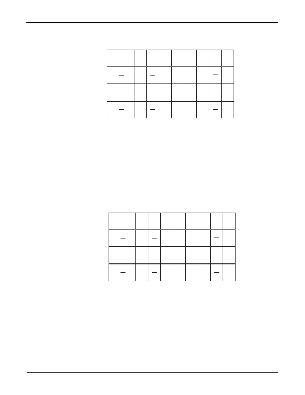
Section 3: Operation S46/S46T/S46L Microwave Switch System Instruction Manual
Events: PON = Power On
CME = Command Error
EXE = Execution Error
DDE = Device-Dependent Error
QYE = Query Error
OPC = Operation Complete
128
(2
7
)
32
(25)16(24)8(23)4(22)
1
(2
0
)
(B15 - B8)
PON CME EXE DDE QYE OPC
Bit Position
Event
Decimal Weighting
B7 B5 B4 B3 B2 B1 B0B6
0/1
Val ue
0/10/1 0/1 0/1 0/1
Value: 1 = Enable Standard Event
0 = Disable (Mask) Standard Event
Events: PON = Power On
CME = Command Error
EXE = Execution Error
DDE = Device-Dependent Error
QYE = Query Error
OPC = Operation Complete
128
(2
7
)
32
(25)16(24)8(23)4(22)
1
(2
0
)
(B15 - B8)
PON CME EXE DDE QYE OPC
Bit Position
Event
Decimal Weighting
B7 B5 B4 B3 B2 B1 B0B6
0/1
Value 0/10/1 0/1
0/1 0/1
Value: 1 = Event Bit Set
2 = Event Bit Cleared
Figure 3-13
Standard event enable register
*ESR? - Event Status Register Query - Reads then clears the St andard Event St atus Register
Use this command to acquire the value (in decimal) of the Standard Event Status Register (see
Figure 3-14). The binary equivalent of the returned decimal value determines which bits in the
register are set. The register is cleared when the instrument is turned on.
Figure 3-14
Standard Event Status Register
3-22 Document number: S46-901-01 Rev. F / March 2011
A set bit in this register indicates that a particular event has occurred. For example, for an acquire d
decimal value of 48, the binary equivalent is 00110000. From this binary value, bits B4 and B5 of
the St an dard Event Status Register are set. These bits indicate that a device-depende nt e rror a nd
command error have occurred.
The bits of the Standard Event Status Register are described as follows:
Page 47

S46/S46T/S46L Microwave Switch System Instruction Manual Section 3: Operation
• Bit B0, operation complete: A set bit indicates that all pending selected device operations
are completed and the S46/S46T/S46L is ready to accept new commands. This bit only set s
in response to the
*OPC command. It is not affected by the *OPC? command.
• Bit B1: Not used.
• Bit B2, query error (QYE): A set bit indicates that you attempted to read data from an
empty output queue.
• Bit B3, device-dependent error (DDE): A set bit indicates that an instrument operation did
not execute properly due to some internal condition.
• Bit B4, execution error (EXE): A set bit indicates that the S46/S46T/S46L detected an
error while trying to execute a command.
• Bit B5, command error (CME): A set bit indicates that a command error has occurred.
Command errors include:
– IEEE Std 488.2 synt ax error: S46/S46T/S46L r eceived a message that does not follow
the defined syntax of IEEE Std 488.2.
– Semantic error: S46/S46T/S46L received a command that was misspelled, or received
an optional IEEE Std 488.2 command that is not implemented.
• Bit B6: Not used.
• Bit B7, power on (PON): A set bit indicates that the S46/S46T/S46L has been turned off
and turned back on again since the last time this register has been read.
*IDN? - identification query Reads identification code
The identification code includes the manufacturer, model number, serial number, and firmware
revision levels. Identification codes vary with the model number, output formats, and output types.
Power supplies set for the exponential output format and Keithley output types have the following
codes:
KEITHLEY INSTRUMENTS INC., sss[s], xxxxxxx, yyyyy
Where: sss[s] is the system
(
S46 for both the S46 and S46T; S46L for the S46L)
xxxxxxx is the serial number
yyyyy is the firmware revision level of the digital board ROM
*OPC - operation complete Sets OPC bit
*OPC? - operation complete query Places a “1” in output queue
When *OPC is sent, the OPC bit in the Standard Event Register will set after all pending command
operations are complete. When
pending command operations are complete.
The following syntax rules explain how to use
NOTE Send *OPC or *OPC?, separated by a semicolon, on the same line as another
query. If sent on separate lines, an error occurs. The
sent on the same line with a command that is not a query, or on a separate line
as a command (not a query).
*OPC? is sent, an ASCII “1” is placed in the output queue after all
*OPC and *OPC? with other commands:
*OPC? command can be
*RST - reset Return relay unit to *RST defaults
When the *RST command is sent, the relay unit performs the following operations:
1. Returns the instrument to the RST default conditions (see “Default” column of SCPI.
tables) and opens all relay paths.
Document number: S46-901-01 Rev. F / March 2011 3-23
Page 48

Section 3: Operation S46/S46T/S46L Microwave Switch System Instruction Manual
Event: ESB = Event Summary Bit
MAV = Message Available Bit
EAV = Error Available
MSB = Measurement Summary Bit
32
(2
5
)16(24)
4
(22)
ESBMAV EAV
Bit Position
Event
Decimal Weighting
B7 B5 B4 B3 B2 B1 B0B6
Value 0/1 0/1 0/1
Value: 1 = Enable Service Request Event
0 = Disable (Mask) Service Request Event
2. Cancels all pending commands.
3. Cancels response to any previously received
*OPC and *OPC? commands.
*SRE <NRf> - Service Request Enable Pro gram register
*SRE? - Service Request Enable Query Read register
Parameters Parameter Description
<NRf> = 0 Clears enable register
4 Set EAV bit (Bit 2)
16 Set MAV bit (Bit 4)
32 Set ESB (Bit 5)
255 Set all bits
Use the
*SRE command to program the Service Request Enable Register. Send this command
with the decimal equivalent of the binary value that de termines the desired st ate (0 or 1) of each bit
in the register. This register is cleared when instrument power is turned on.
This enable register is used with the Status Byte Register to generate service requests (SRQ).
With a bit in the Service Request Enable Register set, an SRQ occurs when the corresponding bit
in the Status Byte Register is set by an appropriate event. For more information about register
structure, see the information presented earlier in this section.
The Service Request Enable Register is shown in Figure 3-15. Notice that the decimal weight of
each bit is included in the illustration. The sum of the decimal weights of the bits that you wish to
set is the value that is sent with the
*SRE command. For example, to set the ESB and MAV bits of
the Service Request Enable Register, send the following command:
*SRE 48
Where: ESB (bit B5) = 32
MAV (bit B4) = 16
<NRf> = 48
The contents of the Service Request Enable Register can be read using the
*SRE? query
command.
Figure 3-15
Service Request Enable Register
3-24 Document number: S46-901-01 Rev. F / March 2011
Page 49

S46/S46T/S46L Microwave Switch System Instruction Manual Section 3: Operation
Events: MSS = Master Summary Status
RQS = Request Service
ESB = Event Summary Bit
MAV = Message Available
EAV = Error Available
MSB = Measurement Available Bit
32
(2
5
)16(24)
4
(22)
ESBMAV EAV
MSS
RQS
Bit Position
64
(2
6
)
Event
Decimal Weighting
B7 B5 B4 B3 B2 B1 B0B6
Value 0/1 0/1 0/1 0/1
Value: 1 = Event Bit Set
0 = Event Bit Cleared
*STB? - Status Byte Query Read Status Byte Register
Use the *STB? query command to acquire the value (in decimal) of the Status Byte Register. The
Status Byte Register is shown in Figure 3-16. The binary equivalent of the decimal value
determines which bits in the register are set.
Figure 3-16
Status Byte Register
Document number: S46-901-01 Rev. F / March 2011 3-25
All bits in this register (except Bit B6) are set by other event registers and queue s. Bit 6 sets when
one or more enabled conditions occur.
The
*STB? query command does not clear the Status Byte Register. This register can only be
cleared by clearing the related registers and queues.
For example, for an acquired decimal value of 48, the binary equivalent is 00110000. This binary
value indicates that bits 4 and 5 of the Status Byte Register are set.
The bits of the Status Byte Register are described as follows:
• Bit 0: Not used.
• Bit 1: Not used.
• Bit 2, error available (EAV): A set bit indicates that an error or status message is present in
the error queue. The message can be read using one of the following SCPI commands:
• Bit 3: Not used.
• Bit 4, message available (MA V): A set bit indicates that a message is present in the output
queue. The message is sent to the computer when the S46 /S46T/S46 L is addresse d to talk.
• Bit 5, event summary bit (ESB): A set bit indicates that an enabled standa rd event has
occurred. The event can be identified by reading the Standard Event Status Register using
the
*ESE? query command.
• Bit 6, master summary status (MSS)/request service (RQS): A set bit indicates that one
or more enabled status byte conditions have occurred. Read the MSS bit by using the
query command, or perform a serial poll to detect the occurrence of a service request (RQS
bit set).
• Bit 7: Not used.
STB?
Page 50

Section 3: Operation S46/S46T/S46L Microwave Switch System Instruction Manual
*TST? - self-test query Run self test and read result
Use this query command to perform a self-test for the system.
When the instrument is addressed to talk, the coded result is sent from the output queue to the
computer. A returned value of one (1) indicates that the test passed, and a value of zero (0)
indicates that the test failed.
*W AI - wait-to-continue Wait until previous commands are completed
Effectively, the *WAI command is a no-op (no operation) for the relay unit and, therefore, does not
need to be used.
Two types of device commands exist:
Sequential commands: A command whose operations are allowed to finish before the next
command is executed.
Overlapped commands: A command that allows the execution of subsequent commands while
device operations of the overlapped command are still in progress.
The *WAI command is used to suspend the execution of subsequent commands until the device
operations of all previous overlapped commands are finished. The
for sequential commands.
*WAI command is not needed
Errors
Table 3-14 summarizes error and status messages that can be read with :SYST:ERR?
Table 3-14
Error and status message
Number Description Event
-440 Query UNTERMINATED after indefinite response EE
-430 Query DEADLOCKED EE
-420 Query UNTERMINATED EE
-410 Query INTERRUPTED EE
-350 Queue overflow SYS
-330 Self-test failed EE
-260 Expression error EE
-241 Hardware missing EE
-224 Illegal parameter value EE
-223 Too much data EE
-222 Data out of range EE
-221 Settings conflict EE
-220 Parameter error EE
-215 Arm deadlock EE
-214 Trigger deadlock EE
-213 Initialization ignored EE
-212 Arm ignored EE
-211 Trigger ignored EE
-210 Trigger error EE
-200 Execution error EE
EE = error event
SE = status event
SYS = system error event
3-26 Document number: S46-901-01 Rev. F / March 2011
Page 51

S46/S46T/S46L Microwave Switch System Instruction Manual Section 3: Operation
Table 3-14 (continued)
Error and status message
Number Description Event
-171 Invalid expression EE
-170 Expression error EE
-161 Invalid block data EE
-160 Block data error EE
-158 String data not allowed EE
-154 String too long EE
-151 Invalid string data EE
-150 String data error EE
-148 Character data not allowed EE
-144 Character data too long EE
-141 Invalid character data EE
-140 Character data error EE
-128 Numeric data not allowed EE
-124 Too many digits EE
-123 Exponent too large EE
-121 Invalid character in number EE
-120 Numeric data error EE
-113 Undefined header EE
-1 12 Program mnemonic too long EE
-111
-110
-109 Missing parameter EE
-108 Parameter not allowed EE
-105 GET not allowed EE
-104 Data type error EE
-103 Invalid separator EE
-102 Syntax error EE
-101 Invalid character EE
-100 Command error EE
+000 No error SE
+900 Internal system error EE
EE = error event
SE = status event
SYS = system error event
Header separator error EE
Command header error EE
Document number: S46-901-01 Rev. F / March 2011 3-27
Page 52

Introduction
This section contains service information for the S46/S46T/S46L. The information is organized as
follows:
WARNING No user serviceable parts inside the equipment. The information in this
Section 4
Service Information
• Handling and cleaning precautions
• Coaxial switch performance verification
• Replacing components
• Ordering information
• Factory service
section is intended only for qualified service personnel. Some of the
procedures may expose hazardous voltages that could result in personal
injury or death. Do not perform these procedures unless you are qualified
to do so.
Handling and cleaning precautions
Because of the high-impedance areas on the S46/S46T/S46L, be careful when handling or
servicing the switch to prevent possible contamination. The following precautions should be
observed when servicing the S46/S46T/S46L.
Handling precautions
Observe the following precautions when handling the S46/S46T/S46L:
• Do not touch connector insulators.
• Do not touch any board surfaces or components not associated with the repair.
• Do not touch areas adjacent to electrical contacts.
• When servicing the instrument, wear clean cotton gloves.
• Do not store or operate the S46/S46T/S46L in an environment where dust could settle on
the circuit board.
Circuit board and connector cleaning
• Use dry nitrogen gas to clean any dust off the circuit board and components.
• Clean the contaminated area with methanol, then blow-dry the entire board with dry
nitrogen gas.
• If the connector insulators should become contaminated, either by inadvertent touching, or
from airborne deposits, clean with a cotton swab dipped in clean methanol.
• Before use, allow items cleaned to dry for several hours in a 50° C low-humidity
environment. Use dry nitrogen to decrease drying time.
Page 53

Section 4: Service Information S46/S46T/S46L Microwave Switch System Instruction Manual
Coaxial switch performance verification
The following paragraphs discuss a channel resistance verification procedur e.
CAUTION Contamination will degrade the performance of the S46/S46T/S46L. To
avoid contamination, do not touch the connector mating surfaces.
As is the case with any high-resistance device, the integrity of connectors can be damaged if they
are not handled properly. If connector insulation becomes contaminated, the insulation resistance
will be substantially reduced, affecting RF paths.
Oils and salts from the skin can contaminate connector insulators, reducing thei r resi stance. Also,
contaminants present in the air can be deposited on the insulator surface. To avoid these
problems, never touch the connector insulating material. In addition, use the switch only in clean,
dry environments to avoid contamination.
If the connector insulators become contaminat ed , eit he r by ina d ve rten t touch i ng or from ai rb or ne
deposits, clean with a cotton swab dipped in clean methanol.
NOTE Failure of any performance verification test may indicate that the instrument is
contaminated. See Handling and cleaning precautions
information on cleaning the controller.
earlier in this section for
Environmental conditions
All verification measurements should be made at an ambient temperature between 18° C and
28° C, and at a relative humidity of less than 70 percent.
Recommended equipment
Table 4-15 summarizes the e quipmen t nece ssary for per formance verification (chann el resist an ce
tests). Required cables and multimeter may be purchased from Keithley Instruments.
Table 4-15
Recommended verification equipment
Manufacturer/Model Equipment description (Qty) Specifications
Keithley Model 2010 Digital multimeter (1) 10 Ω range, 60 ppm
Keithley S40-0217 SMA F/F adapter (1)
Keithley S40-0218 BNC/F to single banana plug (2)
adapter
Keithley S40-0219 BNC/M to SMA/M cable (2) 0.609 m (24 in.) long
Channel resistance test s
Perform the following steps to verify the switch contact is closing properly, the switch resistance is
within specification, and that the switch opens properly.
1. Turn on the Model 2010 digital multimeter (DMM) and allow it to warm up for one hour
before making measurements.
4-2 Document number: S46-901-01 Rev. F / March 2011
Page 54

S46/S46T/S46L Microwave Switch System Instruction Manual Section 4: Service Information
2. Connect the two S40-0218 adapters (BNC to single banana plug) to the two
S40-0219 cables (BNC/M).
3. Set the Model 2010 to the 2-wire 10 Ω range.
4. Connect the two banana plug ends to the DMM INPUT jacks.
5. Short the free ends of the cables together using the SMA F/F adapter.
6. Enable REL on the Model 2010 set residual resistance to a null value. Leave REL enabled
for the entire test.
7. Remove the SMA F/F adapter.
8. Connect the cables to the switch common port and port under test.
9. Close the switch port.
10. Note the resistance reading on the Model 2010, verifying that it is <0.3 Ω.
11. Open the switch.
12. Note the resistance reading on the Model 2010, verifying that it indicates an open circuit.
13. Repeat measurements for all switch ports.
RF performance verification
Use a vector network analyzer (VNA) to verify switch RF performance. Refer to VNA operating
instructions. Relay specifications are listed in the product specifications located on the Keithley
Instruments website (www.keithley.com/support
).
Document number: S46-901-01 Rev. F / March 2011 4-3
Page 55

Section 4: Service Information S46/S46T/S46L Microwave Switch System Instruction Manual
Model 2010 DMM
2010 MULTIMETER
RANGE
!
F
500V
PEAK
FRONT/REAR
3A 250V
AMPS
HI
LO
INPUTS
350V
PEAK
1000V
PEAK
SHIFT
LOCAL
POWER
RANGE
R
SHIFT
CH1REM
TALK
LSTN
SRQ
STAT
REL FILT
4W
BUFFER
MATH
REAR
SCAN
TIMER
STEP CH2 CH3 CH4 CH5 CH6 CH7 CH8 CH9 CH10
HOLD TRIG FAST MED SLOW AUTO ERR
INPUT
SENSE
W 4 WIRE
AUTO
Closed
Relay
Contact
Common
System 46 Relay
Under Test. See Section 2
for detailed connections.
Relay
Under Test
SMA F/F Adapter
(S40-0217)
BNC to single
banana plug adapter
(S40-0218)
(2 places)
BNC/M to
SMA/M cables
(S40-0219)
(2 places)
EXIT ENTER
DIGITS RATE
RELFILTER
TRIG
EX TRIG
STORE
RECALL
OPEN CLOSE
DCV
DCI
MX+B
%
dBm
ACV
ACI
ý2 ý4
FREQ
TEMP
dB
CONT
PERIOD SENSOR
LIMITS ON/OFFDELAY
HOLD
SAVE SETUP
CONFIG HALT
TYPE
RS232
GPIB
RATIO
STEP SCAN
DRYCKT O COMP
CAL TEST
>>
>>
Figure 4-17
Channel resistance test conn ections
Replacing components
Replacing relays
You can replace defective relays without removing the top cover of the S46. To obtain a
replacement relay, order the applicable relay kit. Table 4-16 lists the part numbers for the relays
that can be ordered from Keithley Instruments.
4-4 Document number: S46-901-01 Rev. F / March 2011
Page 56

S46/S46T/S46L Microwave Switch System Instruction Manual Section 4: Service Information
NOTE Make sure that you order the relay kit for the applicab le system (S46, S46T, or S46L).
Relay kits contain components and instructions appropriate for your specific system.
Table 4-16
S46/S46T/S46L relay kits
System Relay kit model number Description Relay location
S46 S46-SPDT-KIT 18GHz SPDT 1 to 8
S46-SP4T-KIT 18GHz SP4T A to D
S46-SP6T-KIT 18GHz SP6T A to D
S46-SPDT-KIT-R 18GHz SPDT 1 to 8
S46-SP4T-KIT-R 18GHz SP4T A to D
S46-SP6T-KIT-R 18GHz SP6T A to D
S46-SPDT-KIT-26 26.5GHz SPDT 1 to 8
S46-SP4T-KIT-26 26.5GHz SP4T A to D
S46-SP6T-KIT-26 26.5GHz SP6T A to D
S46-SPDT-KIT-40 40GHz SPDT 1 to 8
S46-SP4T-KIT-40 40GHz SP4T A to D
S46-SP6T-KIT-40 40GHz SP6T A to D
S46T S46T-SPDT-KIT 18GHz SPDT 1 to 8
S46T-SP4T-KIT 18GHz SP4T A to D
S46T-SP6T-KIT 18GHz SP6T A to D
S46T-SPDT-KIT-26 26.5GHz SPDT 1 to 8
S46T-SP4T-KIT-26 26.5GHz SP4T A to D
S46T-SP6T-KIT-26 26.5GHz SP6T A to D
S46T-SPDT-KIT-T 18GHz SPDT 1 to 8
S46T-SPDT-KIT-26T 26.5GHz SPDT 1 to 8
S46T-SP4T-KIT-T 18GHz SP4T A to D
S46T-SP6T-KIT-T 18GHz SP6T A to D
S46T-SP4T-KIT-26T 26.5GHz SP4T A to D
S46T-SP6T-KIT-26T 26.5GHz SP6T A to D
S46T-XFER-KIT 18GHz XFER A to D
S46T-XFER-KIT-26 26.5GHz XFER A to D
S46T-MSPDT-KIT 18GHz SPDT A to D
S46T-MSPDT-KIT-26 26.5GHz SPDT A to D
S46L S46L-SPDT-KIT-L 20 Ghz SPDT 1 to 4
S46L-SP6T-KIT-T 18 Ghz SP6T A to D
Relay replacement
WARNING Relay replacement should be performed by qualified service pe rsonnel
only. Do not perform this procedure unless you are qualified to do so.
Before replacing a relay, turn off the power and disconnect the line cord
from the instrument. Remove any signal connections from all relays
Document number: S46-901-01 Rev. F / March 2011 4-5
Page 57

Section 4: Service Information S46/S46T/S46L Microwave Switch System Instruction Manual
Mainframe replacement part s
Replacement parts for the mainframe can be obtained directly from Keithley Instruments. See the
Keithley Instruments website (www.keithley.com
WARNING Use only the parts specified on the Keithley Ins trume nt s we b si te
(www.keithley.com
may expose the operator to hazardous voltages that could result in
personal injury or death. Do not attempt to replace parts or otherwise
service the equipment unless you are qualified to do so.
) when servicing the equipment. Use of improper parts
) for specific part numbers.
Replacement precautions
CAUTION Observe the following precautions when replacing components:
• To avoid contamination which could degrade switch performance, always
handle the switch only by the covers and side edges. Do not touch the
connector, board surfaces, or components on the switch.
• Use care when removing components from the PC board to avoid pulling
traces away from the circuit board. Before attempting to remove a relay,
use an appropriate desoldering tool to clear each mounting hole
completely free of solder.
Soldering considerations
When using solder on the circuit board, observe the following precautions:
• Use SAC Tin/Silver/Copper on lead free PC boards which are identified with a "Lead Free"
label. Use Tin/Lead solder on non-lead free boards.
• Use an OA-based (organic activated) flux, and take care not to spread the flux to other
areas of the circuit board.
• Remove the flux from the work areas when the repair has been completed. Use pure water
along with clean cotton swabs or a clean soft brush to remove the flux.
• Once the flux has been removed, swab only the repa ired area with methanol, then blow dry
the board with dry nitrogen gas.
• After cleaning, allow the card to dry in a 50° C low-humidity environment for several hours
before use.
Disassembly
To disassemble the S46/S46T/S46L in order to gain access to and replace the relays or other
components, perform the following steps (refer to Figure 4-17 and Figure 4-18):
WARNING Before disassembly, disco nnect all power sources and remove the
instrument from the instrument rack.
1. Disconnect all power sources and remove the S46 from the instrument rack.
2. Remove the screws that secure the top cover.
4-6 Document number: S46-901-01 Rev. F / March 2011
Page 58

S46/S46T/S46L Microwave Switch System Instruction Manual Section 4: Service Information
Top cover
Digital board
Relays
Front
cover
L-brackets
Relays
Power
supply
Rear cover
Power module
3. Remove the top cover.
4. Remove the screws that secure the digital board assembly to the chassis.
5. Remove the IEEE-488 connector nuts from the rear panel.
6. Remove the digital board from the chassis.
7. Remove the screws that secure the power supply to the chassis, then remove the po we r
supply.
To assemble the S46/S46T/S46L, reverse the disassembly instructions. Make sure all parts are
properly seated and secured, and that all connections are made properly.
Figure 4-18
S46 exploded view
Document number: S46-901-01 Rev. F / March 2011 4-7
Page 59

Section 4: Service Information S46/S46T/S46L Microwave Switch System Instruction Manual
Top cover
Relays
Relays
NOTE Refer to Figure 4-2 for exploded views of
Digital board, Power supply, Power module,
and Rear cover.
Figure 4-19
S46T exploded view
4-8 Document number: S46-901-01 Rev. F / March 2011
Page 60
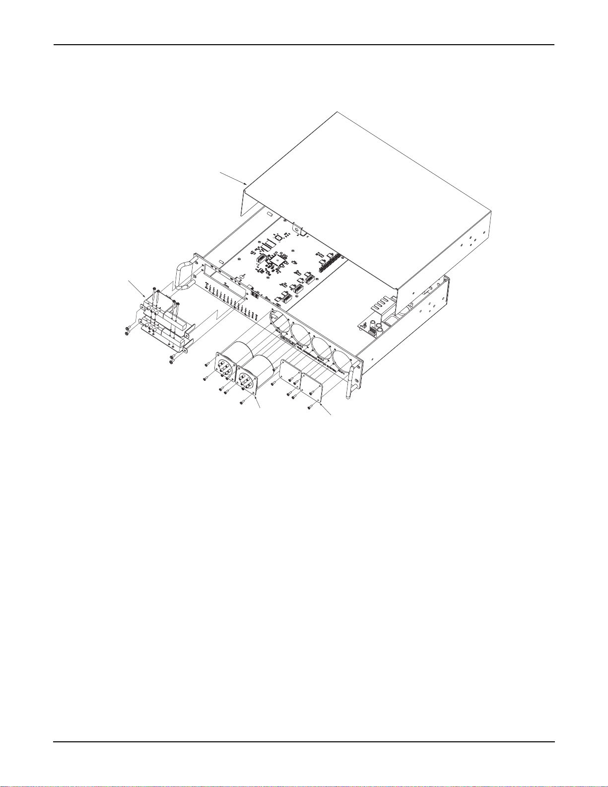
S46/S46T/S46L Microwave Switch System Instruction Manual Section 4: Service Information
Top cover
Relays
Cover plate, used in
positions A - D when
no relay is installed
Relays
NOTE Refer to the S46 exploded view
figure for exploded views of digital
board, power supply, power
module, and rear cover.
Figure 4-20
S46L exploded view
Ordering information
To place an order or to obtain information concerning replacement parts, contac t your loca Keithley
Instruments representative or call 1-888-KEITHLEY. When ordering parts, be sure to include the
following information:
• Switch controller model number (S46/S46T/S46L)
• Serial number
• Part description
• Component designation (if applicable)
• Keithley part number
Factory service
If you need to return your S46/S46T/S46L to Keithley Instruments for repair, perform the following:
• Call the Repair Department at 1-800-552-1115 for a Return Material Authorization (RMA)
• Carefully pack the instrument in the original packing carton.
• Write ATTENTION REPAIR DEPARTMENT and the RMA number on the shipping label.
Document number: S46-901-01 Rev. F / March 2011 4-9
number.
Page 61

Index
Symbols
*CLS .......................................................3-21
*ESE
.......................................................3-21
*ESE?
.....................................................3-21
*ESR?
.....................................................3-22
*IDN?
......................................................3-23
*OPC
......................................................3-23
*OPC?
....................................................3-23
*RST
.......................................................3-23
*SRE
.......................................................3-24
*SRE?
.....................................................3-24
*STB?
.....................................................3-25
*TST?
.....................................................3-26
*WAI
.......................................................3-26
Numerics
16-bit status register ...............................3-19
B
Bus connections .......................................3-2
C
Card cleaning ...........................................4-1
Channel resistance tests
Circuit board removal
CLEar
.....................................................3-12
Clearing registers and queues
CLOSe
......................................................3-7
CLOSe?
....................................................3-7
Coaxial switch performance verification
Command diagram
Command messages
Commands and parameters
Common commands
Configuration
Connections
Connector integrity
Controlling relay connections
............................................2-1
.....................................1-4, 2-1
Bus
...................................................3-2
introduction
...............................................2-8
Power
..........................4-2
.............. 4-7, 4-8, 4-9
...............3-18
...................................3-4
...............................3-3
.....................3-2
..............................3-20
.......................................2-1
.................................2-11
...................3-5
E
Enable registers .....................................3-14
Environmental conditions
ERRor?
...................................................3-12
Error queue
Event register sets
Example command
Exploded view
............................................3-15
......................... 4-7, 4-8, 4-9
.........................4-2
..................................3-13
...................................3-4
...4-2
F
Factory service ......................................... 4-9
Flux
.......................................................... 4-6
G
General information ................................. 1-1
GPIB control connection
GPIB primary address
.......................... 2-6
.............................. 2-8
H
Handling ................................................... 4-1
Handling precautions
.......................2-1, 4-1
I
Input/output connections .......................... 2-5
Insertion loss
Inspection for damage
.......................................... 2-12
............................. 1-2
L
Layout ...................................................... 2-1
M
Manual addenda ...................................... 1-2
Maximum signal considerations
Message exchange protocol
Multiple response messages
............... 3-1
....................3-6
................... 3-6
O
OPEN ....................................................... 3-8
ALL
..................................................3-8
Opening or closing the relay
Operation
Introduction
RS-232
Output queue
Overview
...................................... 3-1
............................................. 3-1
......................................... 3-15
..................................................1-1
.................. 3-26
P
Parameter types ....................................... 3-3
Path isolation
Performance verification
performance verification
PRESet
Primary address
primary address
Program message terminator (PMT)
Programming enable registers
Programming syntax
......................................... 2-12
.......................... 4-2
........................... 4-2
.................................................. 3-10
....................................... 3-2
....................................... 2-8
............... 3-19
................................3-2
....... 3-4
Document number: S46-901-01 Rev. F / March 2011 Index-1
Page 62

Index S46/S46T/S46L Microwave Switch System Instruction Manual
Q
Query Commands ....................................3-3
QUEue
....................................................3-10
Queues
...................................................3-14
R
Reading registers ...................................3-20
Recommended verification equipment
Relay replacement
Repacking
Repair department phone number
Replacement parts
Replacement precautions
Replacing components
Response message terminator (RMT)
Response messages
RFI/EMI
..................................................2-12
RS-232 connector terminals
....................................4-6
.................................................1-2
...................................4-6
.........................4-6
.............................4-4
................................3-5
.....................2-8
.....4-2
............4-9
.....3-6
S
Schematic .................................................2-3
Sending a response message
Serial polling and SRQ
Service request enable register
Shipment contents
Short-form commands
Signal
connections
Signal considerations
SNUMber
Soldering considerations
Specifications
Status byte and SRQ
Status Byte Register
Status model
Switching considerations
................................................3-12
....................................1-2
......................................2-4
...............................3-1
...........................................1-2
..............................3-16
...............................3-17
.............................................3-6
..................3-5
...........................3-18
..............3-18
..............................3-3
..........................4-6
........................3-26
U
Unpacking and inspection ........................1-2
V
VERsion? ................................................3-12
Voltage Standing Wave Ratio
.................2-12
Index-2 Document number: S46-901-01 Rev. F / March 2011
Page 63

12/06
Specifications are subject to change without notice.
All Keithley trademarks and trade names are the property of Keithley Instruments, Inc.
All other trademarks and trade names are the property of their respective companies.
A GREATER MEASURE OF CONFIDENCE
Keithley Instruments, Inc.
Corporate Headquarters • 28775 Aurora Road • Cleveland, Ohio 44139 • 440-248-0400 • Fax: 440-248-6168 • 1-888-KEITHLEY • www.keithley.com
 Loading...