

Page 1
INSTRUCTION MANUAL
Model 750 Printer
Page 2

WARRANTY
We warrant each of our products to be free from defects in material
and workmanship. Our obligation under this warranty is to repair
or replace any instrument or part thereof which, within a year after
shipment, proves defective upon examination. We will pay local
domestic surface freight costs.
To exercise this warranty, write or ca~ll your local Keithley representative, or contact Keithley headquarters in Cleveland, Ohio.
You will be given prompt assistance and shipping instructions.
REPAIRS AND
CALIBRATION
Keithley Instruments maintains a complete repair and calibration
service as well as a standards laboratory in Cleveland, Ohio.
A Keithley service facility at our Munich, Germany office is
available for our customers throughout Europe. Service in the
United Kingdom can be handled at our office in Reading. Addition-
ally, Keithley representatives in most countries maintain service
and calibration facilities.
To insure prompt repair or recalibration service, please contact
your local field representative or Keithley headquarters directly
before returning the instrument. Estimates for repairs, normal
recalibrations and calibrations traceable to the National Bureau of
Standards are available upon request.
KEITHLEY
The measurement engineers.
Keithley Instruments, Inc., 28775 Aurora Road, Cleveland, Ohio 44139. (216) 248-0400
European Headquarters: Heiglhofstrasse 5, D-8000 Munchen 70 West Germany, (089) 7144065
United Kingdom: 1 Boulton Road, Reading, Berkshire, (0734) 661267
France: 44 Rue Anatole France, F-91121 Palaiseau (01) 014-22-06
Page 3
INSTRUCTION MAYUAL
Model 750 Printer
OCOPYRIGHT 1976, KEITHLEY INSTRUMENTS, INC.
SECOND PRINTING, AUG. 1978, CLEVELAND, OHIO, U.S.A.
DOCUMENT NO. 27965, REVISION CODE AA.
Page 4
INSTRUCTION MANUAL
Model 750 Printer
CONTENTS
Section
Page
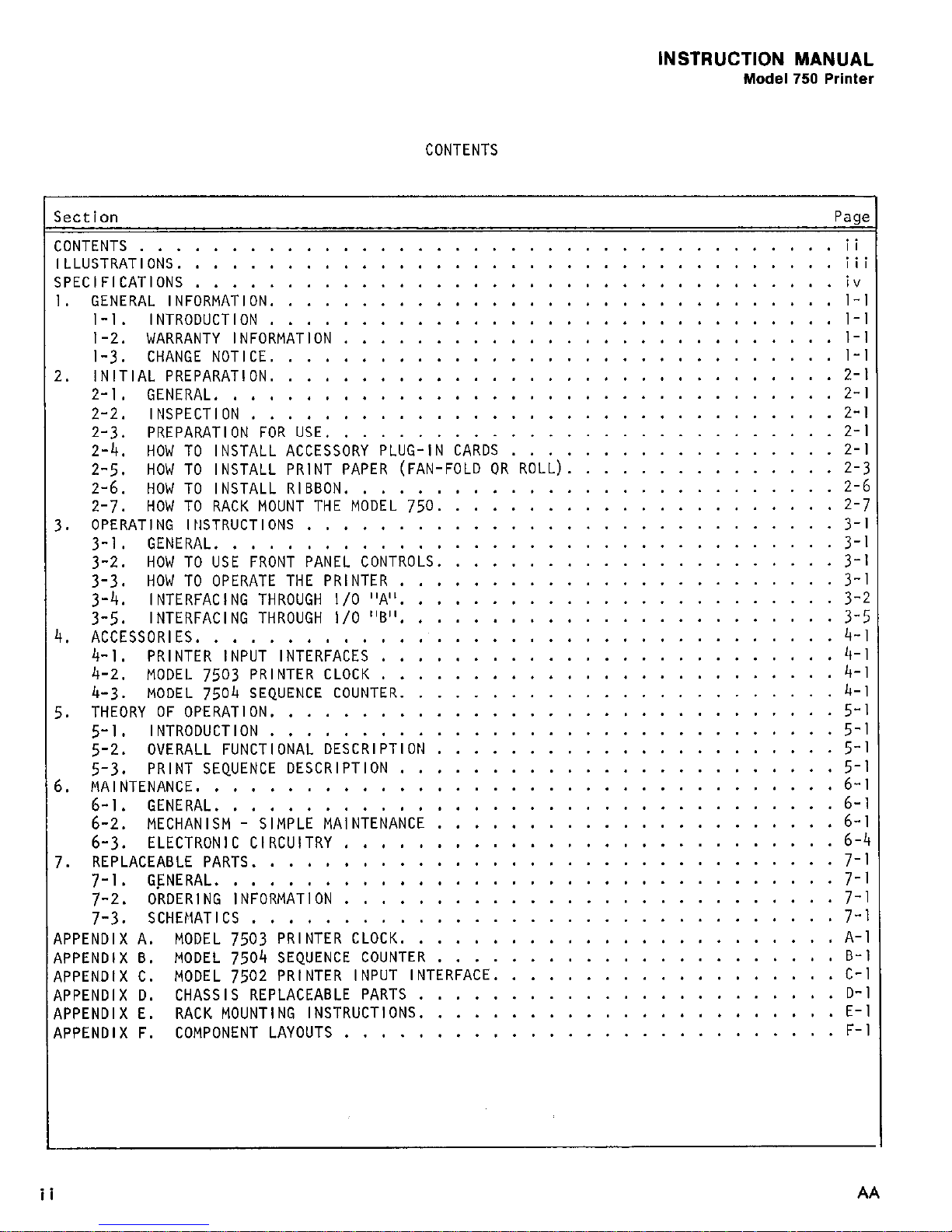
CONTENTS
......................................
ii
ILLUSTRATIONS.
................................... iii
SPECIFICATIONS
...................................
iv
1. GENERAL INFORMATION.
.............................. l-l
l-l. INTRODUCTION
............................... l-l
1-2. WARRANTY INFORMATION
........................... l-l
l-3.
CHANGE NOTICE.
.............................. l-l
2.
INITIAL PREPARATION.
.............................. 2-l
2-l. GENERAL..................................2- I
2-2. INSPECTION
................................ 2-l
2-3. PREPARATION FOR USE.
...........................
2-l
2-4.
HOW TO INSTALL ACCESSORY PLUG-IN CARDS
..................
2-l
2-5.
HOW TO INSTALL PRINT PAPER (FAN-FOLD OR ROLL).
..............
2-3
2-6.
HOW TO INSTALL RIBBON.
..........................
2-6
2-J.
HOW TO RACK MOUNT THE MODEL
750.
.....................
Z-J
3.
OPERATING INSTRUCTIONS
.............................
3-l
3-l.
GENERAL ..................................
3-l
3-2.
HOW TO USE FRONT PANEL CONTROLS.
.....................
3-1
3-3.
HOW TO OPERATE THE PRINTER
........................
3-l
3-4.
INTERFACING THROUGH I/O "A".
.......................
3-2
3-5.
INTERFACING THROUGH I/O "6".
.......................
3-5
4.
ACCESSORIES.
..................................
4-l
4-l.
PRINTER INPUT INTERFACES
.........................
4-l
4-2.
MODEL
7503
PRINTER CLOCK
.........................
4-l
4-3.
MODEL
7504
SEQUENCE COUNTER.
.......................
4-1
5.
THEORY OF OPERATION.
..............................
5-l
5-l.
INTRODUCTION
...............................
5-l
5-2.
OVERALL FUNCTIONAL DESCRIPTION
......................
5-l
5-3.
PRINT SEQUENCE DESCRIPTION
........................
5-1
6.
MAINTENANCE.
..................................
6-l
2:::
GENERAL ..................................
6-1
MECHANISM - SIMPLE MAINTENANCE
......................
6-1
6-3.
ELECTRONIC CIRCUITRY
...........................
6-4
7.
REPLACEABLE PARTS.
...............................
7-1
J-1.
GENERAL ..................................
7-1
7-2.
ORDERING INFORMATION
...........................
7-l
7-3.
SCHEMATICS
................................
J-l
APPENDIX A.
MODEL
7503
PRINTER CLOCK.
....................... A-l
APPENDIX B.
MODEL 7504 SEQUENCE COUNTER
......................
B-l
APPENDIX C.
MODEL 7502 PRINTER INPUT INTERFACE.
..................
C-l
APPENDIX D.
CHASSIS REPLACEABLE PARTS
.......................
D-l
APPENDIX E. RACK MOUNTING INSTRUCTIONS.
......................
E-l
APPENDIX F.
COMPONENT LAYOUTS
...........................
F-l
ii
AA
Page 5
INSTRUCTION MANUAL
Model 750 Printer
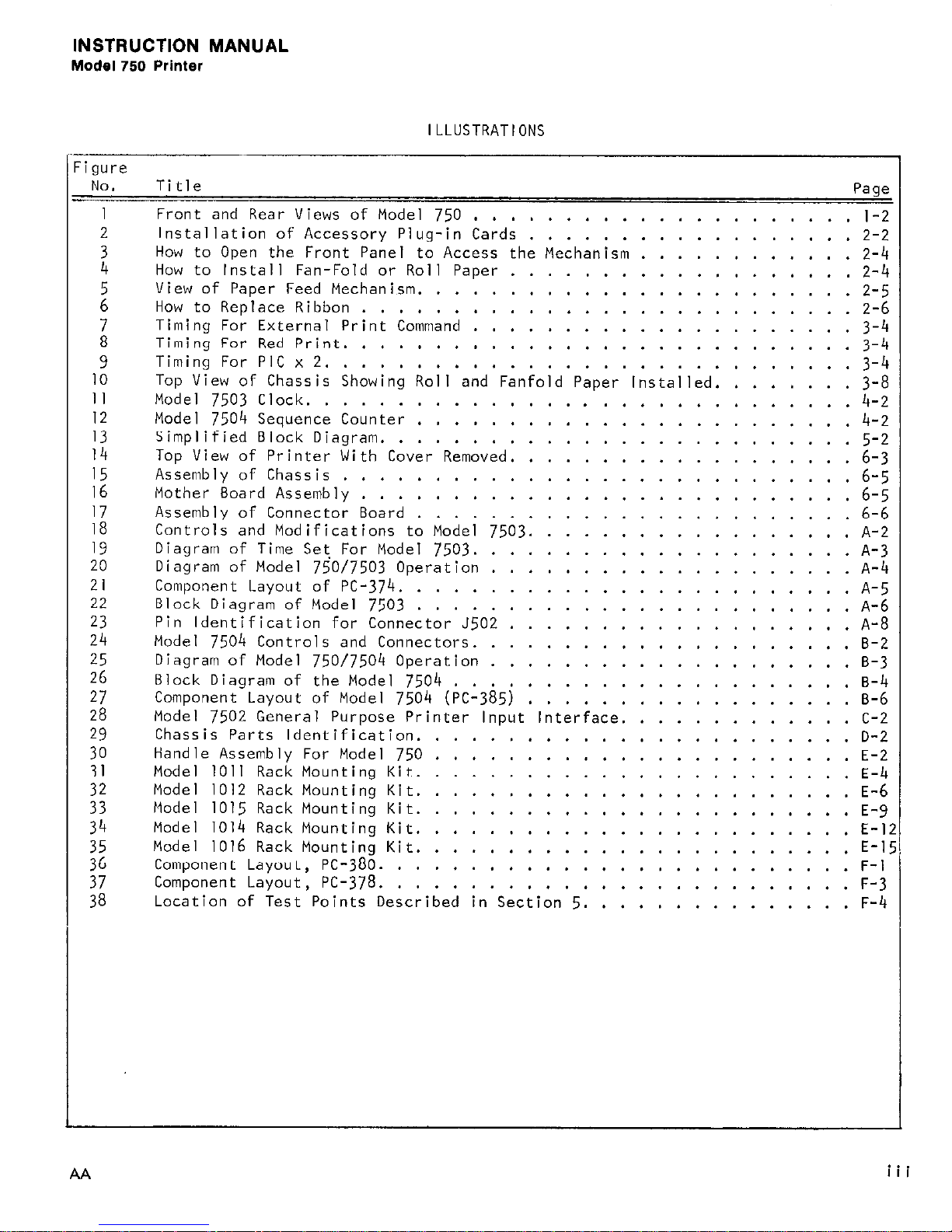
ILLUSTRATIONS
igure
NO. Title
Page
1 Front and Rear Views of Model 750
.....................
l-2
2
Installation of Accessory Plug-in Cards
..................
2-2
2
How to Open the Front Panel to Access the Mechanism ............
2-4
How to Install Fan-Fold or Roll Paper
...................
2-4
2
View of Paper Feed Mechanism.
.......................
2-5
How to Replace Ribbon
...........................
2-6
;
Timing For External Print Command
..................... 3-4
Timing For Red Print.
...........................
3-4
9
Timing For PIC x 2.
............................ 3-4
10
Top View of Chassis Showing Roll and Fanfold Paper Installed.
.......
3-8
II
Model 7503 Clock.
.............................
4-2
12
Model 7504 Sequence Counter
........................
4-2
13
Simplified Block Diagram.
.........................
5-2
14
Top View of Printer With Cover Removed.
..................
6-3
15
Assembly of Chassis
............................
16
6-5
Mother Board Assembly
...........................
6-5
17
Assembly of Connector Board
........................
6-6
18
Controls and Modifications to Model 7503.
.................
A-2
19
Diagram of Time Set For Model 7503.
....................
A-3
20
Diagram of Model
750/7503
Operation
....................
A-4
21
Component Layout of PC-374.
........................
A-5
22
Block Diagram of Model 7503
...
....................................
: :
A-6
23
Pin Identification for Connector J502 A-8
24
Model 7504 Controls and Connectors.
....................
B-2
25
Diagram of Model
750/7504
Operation
....................
B-3
26
Block Diagram of the Model 7504
......................
B-4
27
Component Layout of Model
7504 (~~-385)
..................
B-6
28
Model 7502 General Purpose Printer Input Interface. ............
C-2
::
Chassis Parts Identification.
.......................
D-2
Handle Assembly For Model 750
.......................
E-2
31
Model 1011 Rack Mounting Kit.
.......................
E-4
;:
Model 1012 Rack Mounting Kit.
.......................
E-6
Model 1015 Rack Mounting Kit.
.......................
E-9
34
Model 1014 Rack Mounting Kit.
.......................
E-l
;z
Model 1016 Rack Mounting Kit.
.......................
E-l
Component Layout, PC-380.
.........................
F-l
Component Layout,
PC-378.
.........................
F-3
Location of Test Points Described in Section 5. .............. F-4
AA
iii
Page 6
INSTRUCTION MANUAL
Model 750 Printer
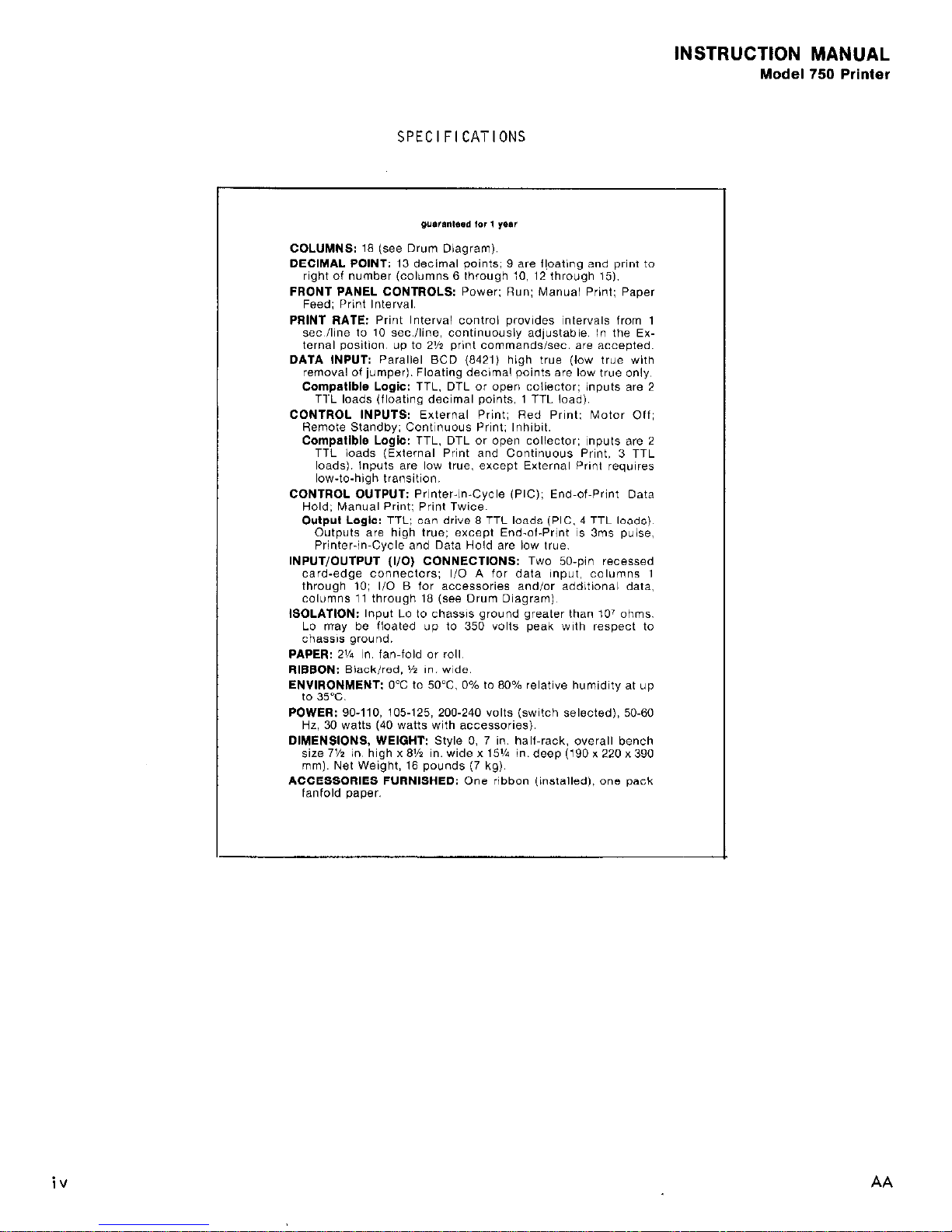
SPECIFICATIONS
low-to-high transition,
CONTROL OUTPUT: Printer-in-Cycle (PIG); End-of-Print Data
Hold: Manual Print: Print Twice.
iv
AA
Page 7

INSTRUCTION MANUAL
Model 750 Printer
SECTION I.
GENERAL INFORMATION
SECTION 1
l-l.
INTRODUCTION.
The Keithley Model 750 Printer is a medium speed, ink impression,
line printer designed for use with Keithley digital measuring instruments and other
digital instrumentation.
a.
Printing Capabilities.
The tlodel 750 records up to 18 columns of data per line.
Columns 3 through I8 print numeric data,
while columns 1 and 2 of the printer are re-
served for measurement units and contain no numeric characters.
Columns 3, 4, 5 can
print certain measurement units (see Table 3-5 on page 3-7). Columns 6 through IO and 12
through 15 contain a floating decimal point which can be printed to the right of any one
of the numeric data columns,
without deleting numerical data in that umn.
Either
adding machine roll paper (Z-1/4 inch width) or fan-fold paper can bf ;ed.
b. Accessory printer Input Interfaces are available for use with t thley digital mea-
suring instruments. The factory-wired interfaces are plug-to-plug cb,,, atible so 'that
installation is very simple to perform. All data is properly encoded and formatted for
printout of data, decimal point, range, and units of measurement (where available at the
digital output). See ACCESSORIES Section 4 for more detailed information regarding
accessory interfaces for Keithley instruments as well as for general purpose applications.
l-2.
WARRANTY INFORMATION. The warranty is given in the Keithley general catalog. If
there is a need for service, contact your Keithley representative or authorized repair
facility as given in our catalog.
l-3.
CHANGE NOTICE. Improvements or changes to the instruvent not incorporated into the
manual will be explained on separate instruction manual addenda sheets.
CAUTION
Since input Lo can float to 350 volts peak with respect to chassis ground, care
should be exercised when making connections to either I/O "A" or "BP.
Turn off
power to all instruments c0nnectp.d before plug-in cards are installed or removed,
or cable connections are made. If I/O "B" is not used, make certain the cover
plate is installed to prevent the possibility of electrical shock.
AA
l-l
Page 8

SECTION 1
INSTRUCTION MANUAL
Model 750 Printer
PAPER CUTTING BAR
JZOI
J202
POWER INDICATOR
DS301
POWER S3OIA
PAPER FEED S3OlB
RUN S301C
MANUAL PRINT S301
'PRINT INTERVAL
s103/~106
LINE VOLTS SIOI
FUSE FIOI
POWER P105
C
FIGURE I.
Front and Rear Views of Model 750.
l-2
AA
Page 9
INSTRUCTION MANUAL
Model 750 Printer
SECTION 2.
INITIAL PREPARATION
SECTION 2
2-l.
GENERAL.
This section provides information needed for incoming inspection and
preparation for use.
2-2. INSPECTION.
The Model 750 was carefully inspected both mechanically and electri-
cally before shipment. Upon receiving the instrument, check for any obvious damage
which may have occurred during transit.
verify the electrical specifications,
Report any damages to the shipping agent. To
follow the procedures in Section 5.
2-3.
PREPARATION FOR USE.
a. How to Set the Line Switch. The rear panel LINE Switch should be set to the
appropriate nominal setting as shown in Table 2-l. For example,
be used is 120 volts,
if the line voltage to
set the LINE Switch to "117".
If the line voltage to be used is
within 105 and llOV, then either range (100 V or 117 V) may be selected.
TABLE 2-l.
Voltage Ranges Useable With Model 750
Range of Voltage Appropriate Setting
Fuse Rating
go - IIOV
I oov
3/4A
105 - l25V
117v
3/4A
200 - 240V 22ov
3/8A
b.
Line Fuse Requirements.
shown in Table 2-l.
The Model 750 uses a 3AB or 3AG Slow-Blow fuse with rating
The line fuse is located on the rear panel as shown in Figure I.
C.
Line Power Connections.
An accessory line cord is furnished with the Model 750.
The 3-wire, 8 foot (244 cm) line cord mates with the rear panel receptacle p]Ol. An
extra line cord can be ordered from Keithley by specifying Keithley Part No. CO-7.
2-4. HOW TO INSTALL ACCESSORY PLUG-IN CARDS.
a. Model 7501 Printer Input Interface Cards.
These cards have card-edge connectors
which mate with I/O "A" receptacle on the Model 750 chassis. Before installinq a card,
remove the cover plate at I/O "A" by pulling the two plastic buttons.
To install the
card align the card-edge to mate with grooved tracks on the chassis as shown in Figure 2.
The "component side"
should face the users right hand when viewing the rear panel as
illustrated. The two plastic buttons should be pulled out (unlocked). After the card
is installed,
lock the card in place by pushing in the buttons on the rear panel. The
Model 7501 can not be inserted in I/O "B".
b.
Models 7502, 7503, and 7504 Plug-In Cards. These cards have card-edge connectors
which mate with I/O "6" receptacle on the Model 750 chassis.
Before installing a card,
remove the cover plate at I/O "B" by pulling the two plastic buttons.
To install the
card align the card-edge to mate with grooved tracks on the chassis as shown in Figure 2.
The "component side"
should face the 'users right hand when viewing the rear panel as
AA
2-1
Page 10
SECTION 2
INSTRUCTION MANUAL
Model 750 Printer
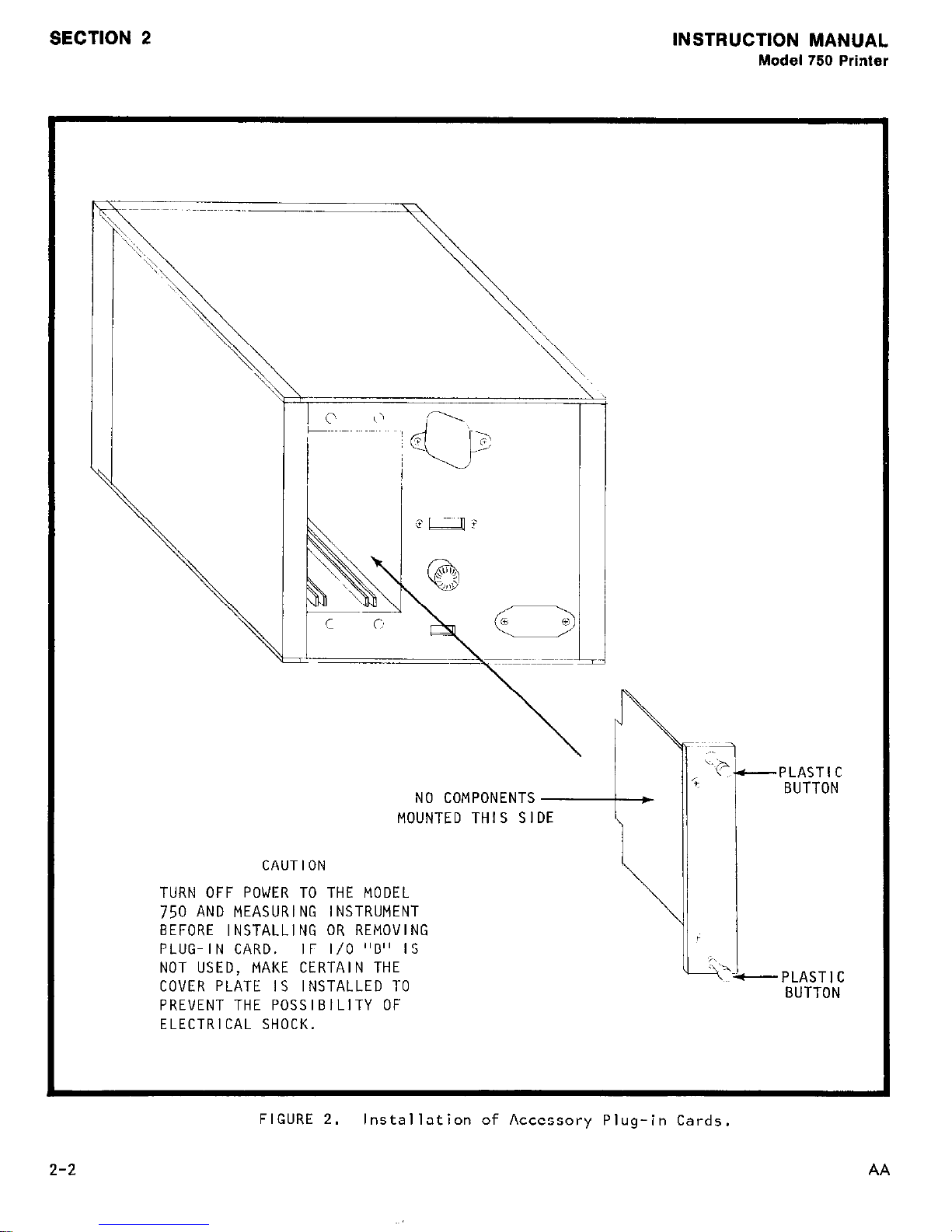
CAUTION
TURN OFF POWER TO THE MODEL
750 AND MEASURING INSTRUMENT
BEFORE INSTALLING OR REMOVING
PLUG-IN CARD. IF I/O "B" IS
NOT USED, MAKE CERTAIN THE
COVER PLATE IS INSTALLED TO
PREVENT THE POSSIBILITY OF
ELECTRICAL SHOCK.
FIGURE 2.
2-2
NO COMPONENTS
MOUNTED THIS SIDE
Installation of Accessory Plug-in Cards.
I t
.\
AA
Page 11
INSTRUCTION MANUAL
Model 750 Printer
SECTION 2
illustrated.
buttons on the rear panel.
7501
cards. The Model 7502 may be installed in either I/O “A” or I/O “B”. Models
and 7504 must be installed in I/O “B” as they will not operate in I/O “A”.
2-5.
tape can be used as a recording medium for the Model
paper is shipped with the printer and is more convenient to install than roll paper.
However,
for installing printer paper. (Extra fan-fold paper may be ordered from Keithley by
specifying Model
a. How to Install Fan-Fold Paper.
shown in Figure 3.
the tray is aligned so that the metal tab is in the front.
ing the tape in the print mechanism.
--
HOW To
I .
Pull out front panel by grasping handle on front panel.
2.
Pull out paper tray.
Place stack of fan-fold paper in pull-out tray as shown in Figure 4.
3.
4. Lift and fold-out the top two layers of paper.
After the card is installed, lock the card in place by pushing in the
I/O “B” has a polarizing pin to prevent insertion of Model
INSTALL PRINT PAPER (FAN-FOLD
the printer will accommodate either paper type.
7505.
See ACCESSORIES section.)
oft
ROLL). Standard
750
2-l/4
Printer.
Use the following procedure
This provides a leader for load-
inch adding machine
A package of fan-fold
Panel swings open as
Be certain
7503
Hold the pack so that the leader is pointing away from the pr’mter and slide the
5.
tray into the tape drawer. When properly installed, the front end of the paper tray
should be just behind the front panel.
6.
Proceed to Paper Feed Instructions in paragraph c.
b.
How to Install Roll-Type Paper.
NOTE
Roll should not exceed Z-3/4 inches in diameter.
I .
Remove the top cover by unscrewing the four Phillips head screws.
2.
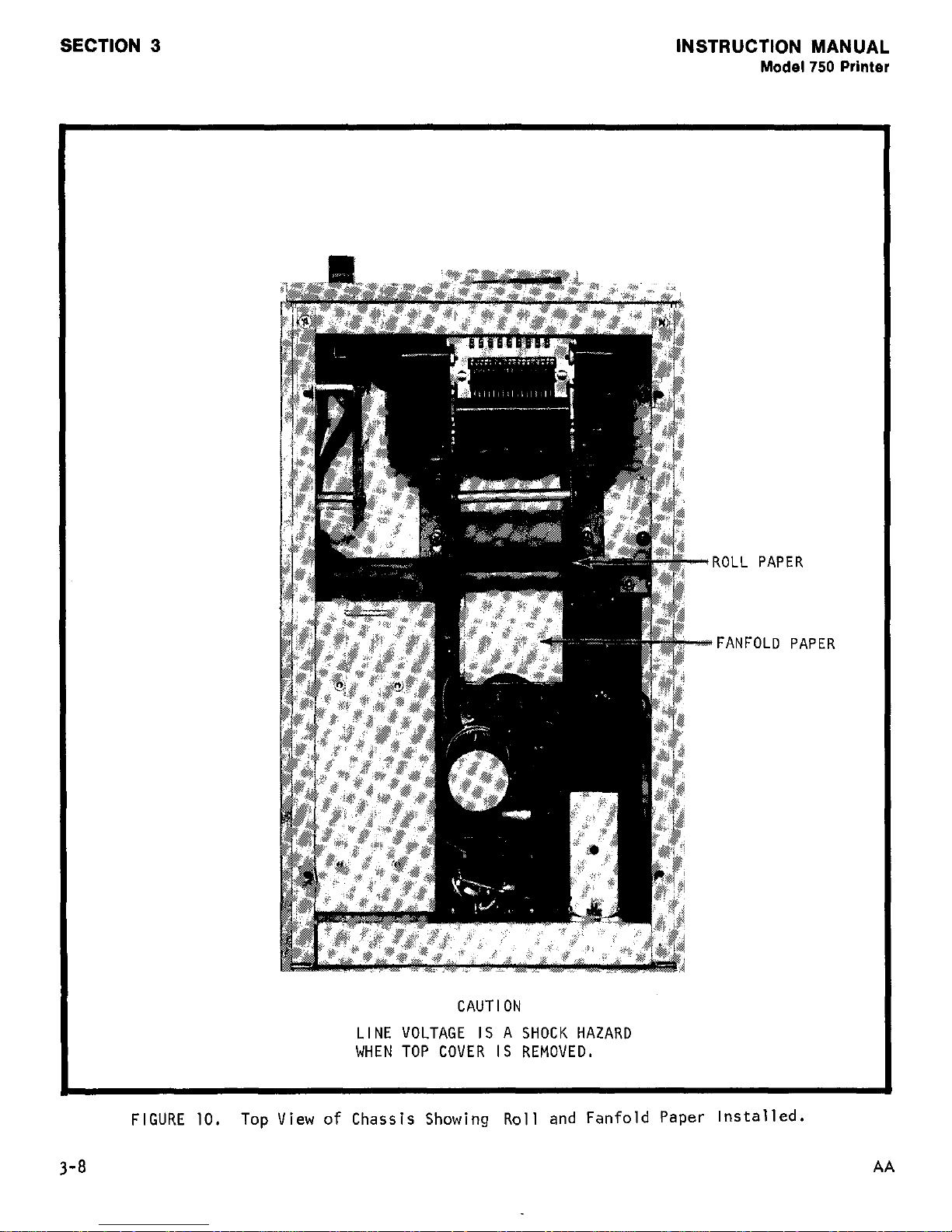
Install the roll paper on the roller pin located as shown in Figure 10
Pull out front panel by grasping handle on front panel.
3.
show in Figure 3.
4.
Grasp the paper roll in one hand and pull out a twelve inch leader.
Point the leader toward the front panel on the printer and, position the paper
5.
rol
I
o that the leader is being pulled off the bottom of the roll.
6.
Slide the paper roll into the roll fixture as shown in Figure 10.
Panel swings open as
Feed the free end of paper under mechanism until it protrudes at the front panel
7.
see
(
‘igure
Replace the top cover.
8.
Proceed to Paper Feed Instructions in paragraph c.
9.
4).
AA
2-3
Page 12

SECTION 2
INSTRUCTION MANUAL
Model 750 Printer
/
+-- -1
PULL OUT AND SLIDE
PANEL TO THE LEFT
'
SO THAT TAB CLEARS
PULL HANDLE
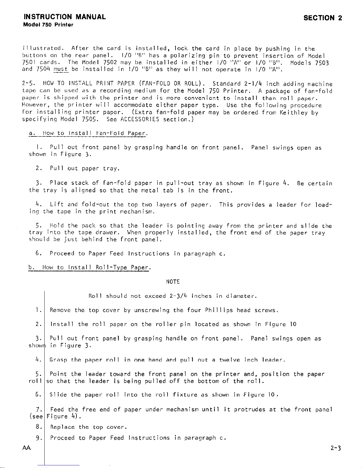
FIGURE
3.
How to Open the Front Panel to Access the Mechanism.
ROLL PAPER
PAPER EXITS
MECHANISM
REAR PANEL
FRONT PANEL
FAN-FOLD PAPER
PAPER TRAY
SIDE VIEW
FIGURE
4.
How to Install Fan-Fold or Roll Paper.
2-4
AA
Page 13
INSTRUCTION MANUAL
Model 750 Printer
SECTION 2
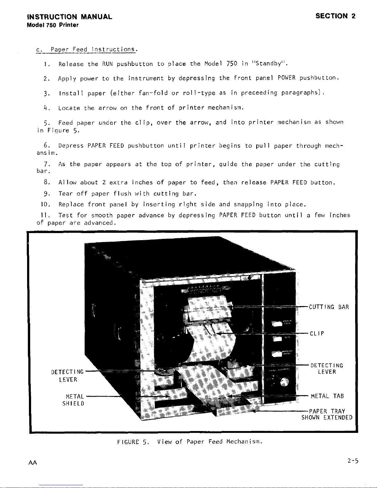
t.
Paper Feed Instructions.
I .
Release the RUN pushbutton to place the Model 750 in "Standby".
2.
Apply power to the instrument by depressing the front panel POWER pushbutton.
3.
Install paper (either fan-fold or roll-type as in preceeding paragraphs).
4.
Locate the arrow on the front of printer mechanism.
5.
Feed paper under the clip,
over the arrow, and into printer mechanism as shown
in Figure
5.
6.
Depress PAPER FEED pushbutton until printer begins to pull paper through mech-
ansim.
7.
As the paper appears at the top of printer, guide the paper under the cutting
bar.
a. Allow about 2 extra inches of paper to feed, then release PAPER FEED button.
9.
Tear off paper flush with cutting bar.
IO. Replace front panel by inserting right side and snapping into place.
Il.
Test for smooth paper advance by depressing PAPER FEED button until a few inches
of paper are advanced.
DE
ITECTIN
LEVER
MET!
SHIEL
FIGURE
5.
View of Paper Feed Mechanisln.
AA
2-5
Page 14
SECTION 2
INSTRUCTION MANUAL
Model 750 Printer
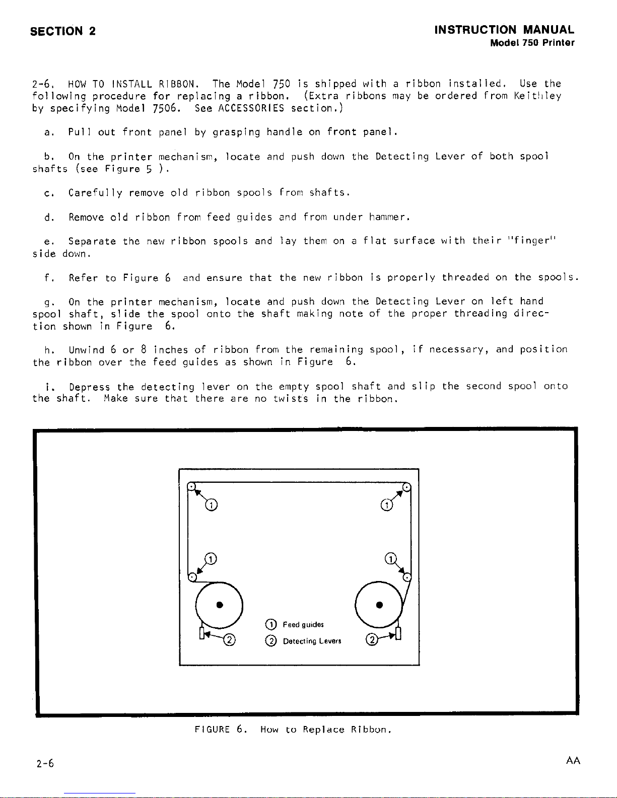
2-6.
HOW TO INSTALL RIBBON.
The Model
750
is shipped with a ribbon installed. Use the
following procedure for replacing a ribbon.
(Extra ribbons may be ordered from Keit!lley
by specifying Model
7506.
See ACCESSORIES section.)
a. Pull out front panel by grasping handle on front panel.
b. On the printer mechanism, locate and push down the Detecting Lever of both spool
shafts (see Figure
5
).
t.
Carefully remove old ribbon spools from shafts.
d.
Remove old ribbon from feed guides and from under hammer.
e.
Separate the new ribbon spools and lay them on a flat surface with their "finger"
side down.
f. Refer to Figure
6
and ensure that the new ribbon is properly threaded on the spools.
9.
On the printer mechanism, locate and push down the Detecting Lever on left hand
spool shaft,
slide the spool onto the shaft making note of the proper threading direc-
tion shown in Figure
6.
h.
Unwind 6 or
8
inches of ribbon from the remaining spool, if necessary, and position
the ribbon over the feed guides as shown in Figure
6.
i. Depress the detecting lever on the empty spool shaft and slip the second spool onto
the shaft. Make sure that there are no twists in the ribbon.
FIGURE 6. How to Replace Ribbon.
2-6
AA
Page 15

INSTRUCTION MANUAL
Model 750 Printer
SECTION 3.
OPERATING INSTRUCTIONS
SECTION 3
3-l. GENERAL.
This section provides information to operate the Model 750 with a variety
of Keithley and other digital measuring instruments.
Information on specific models can
be found in the appropriate Interface manual.
3-2.
HOW TO USE FRONT PANEL CONTROLS.
a. How to Apply Power.
The POWER switch is a "push-push" switch. Depress to apply
power to the instrument.
When the switch is released power is off. The Power Indicator
is lighted when power is on.
b.
How to Feed Paper. The PAPER FEED Switch is a "momentary push" switch.
In the
depressed position it advances papei through the printer mechanism. The switch is used
for loading paper tape or for advancing printed data past the cutting bar.
c.
How to Set Printer to RUN Mode.
The RUN pushbutton is a "push-push" switch.
Depress to allow the printer to be activated by a print command from either of two
sources:
I . Internal print interval.
2.
External Source.
When the switch is released, the printer can be activated only by MANUAL PRINT.
d.
How to Activate the Printer Manually. The MANUAL PRINT Switch is a "momentary
push" switch.
Depress to activate a single line of data. If the switch is depressed
and held in this position, the printer will print data at a rate determined by the PRINT
INTERVAL control. Minimum interval is I second. The external source does not affect
the print interval when MANUAL PRINT is used.
e. How to Set Print Interval. The PRINT INTERVAL control is continuously adjustable
and sets the internal print Interval from a minimum of I ,second'to a maximum of IO
seconds (apprm. The PRINT INTERVAL 'contr,ol also has an EXTERNAL position. In
EXTERNAL the print interval is determined by external print commands.
3-3.
HOW TO OPERATE THE PRINTER.
a. Release POWER Switch (power off).
b. Release RUN Switch (i.e., set to STANDBY mode).
c. Check LINE switch setting as in paragraph
2-3a.
d. Install Model 7501 Printer Input Interface Plug-In Card and/or other accessory
plug-in card as appropriate.
AA
3-l
Page 16
SECTION 3 INSTRUCTION MANUAL
Model 750 Printer
e. Set PRINT INTERVAL control to the appropriate settings.
I.
If an external print interval is to be used, set the PRINT INTERVAL control to
EXT.
2.
If the internal print interval is to be used,
set the PRINT INTERVAL control to
the desired~ position.
f. Connect the line cord.
4.
Depress the POWER Switch.
Power indicator should be lighted.
h. 'Check operation of the Model 750 in STANDBY mode.
(Depress MANUAL PRINT switch
momentarily to cause the Model
750
to print one line.)
i. Depress RUN. This action will cause the Model
750
to initiate printing at inter-
vals determined by the position off the PRINT INTERVAL control.
j.
To halt further printing, release RUN switch.
k. To advance paper through the print mechanism, depress PAPER FEED.
1.
Tear off the printed information by pulling the paper tape along the "cutting bar".
3-4.
INTERFACING THROUGH I/O "A".
a. General. The Model
750
provides a 50-pin Card-edge connector for I/O "A". This
connector may be used with Model
7501
or Model 7502 Plug-In Cards.
Special interfacing
situations where non-Keithley instruments are used may require custom-designed interface
circuitry. Contact your Keithley representative for more information on availability of
interfaces.
Do not install Model
7503
or
7504
cards into I/O "A".
TABLE 3-l.
Logic Definitions for Input Signals
Logic "0"
Logic "1"
0 to +0.5V applied Open input or +2.4V
while sinking current to +5.5V applied while
as listed.
supplying 250pA
See text
b.
Input Signals at I/O "A".
I. Data Columns.
binary coded decimal
The Model 750 may be
WlOl shown in Figure
for Logic
IW’
is
3.2
(Pins l-40) Each data column requires a parallel entry, 4-bit
(BCD) input.
The Model 750 is factory wired for "positive true".
altered by the user to permit "low true" logic by removing jumper
37.
Floating decima.l points are low true only.
Sinking current
milliamperes per line. These lines are identified as follows:
l-l = column I, bit I
l-2 = column I, bit 2
Typical for columns
l-4 = column I, bit 4 I through IO
l-8 = column I, bit 8
3-2
AA
Page 17
INSTRUCTION MANUAL
Model 750 Printer
SECTION 3
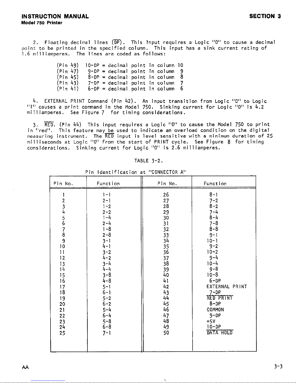
2.
Floating decimal lines (m. This tnput requires a Logic "0" to cause a decimal
point to be printed in the specified column.
This input has a sink current rating of
I.6 milliamperes. The lines are coded as follows:
(Pin 43) IO-DP = decimal point in column IO
(Pin
47)
g-DP = decimal point in column 9
(Pin
45)
8-DP = decimal point in column 8
[;jn z;i
In
7-DP = decimal point in column i
6-DP = decimal point in column
4.
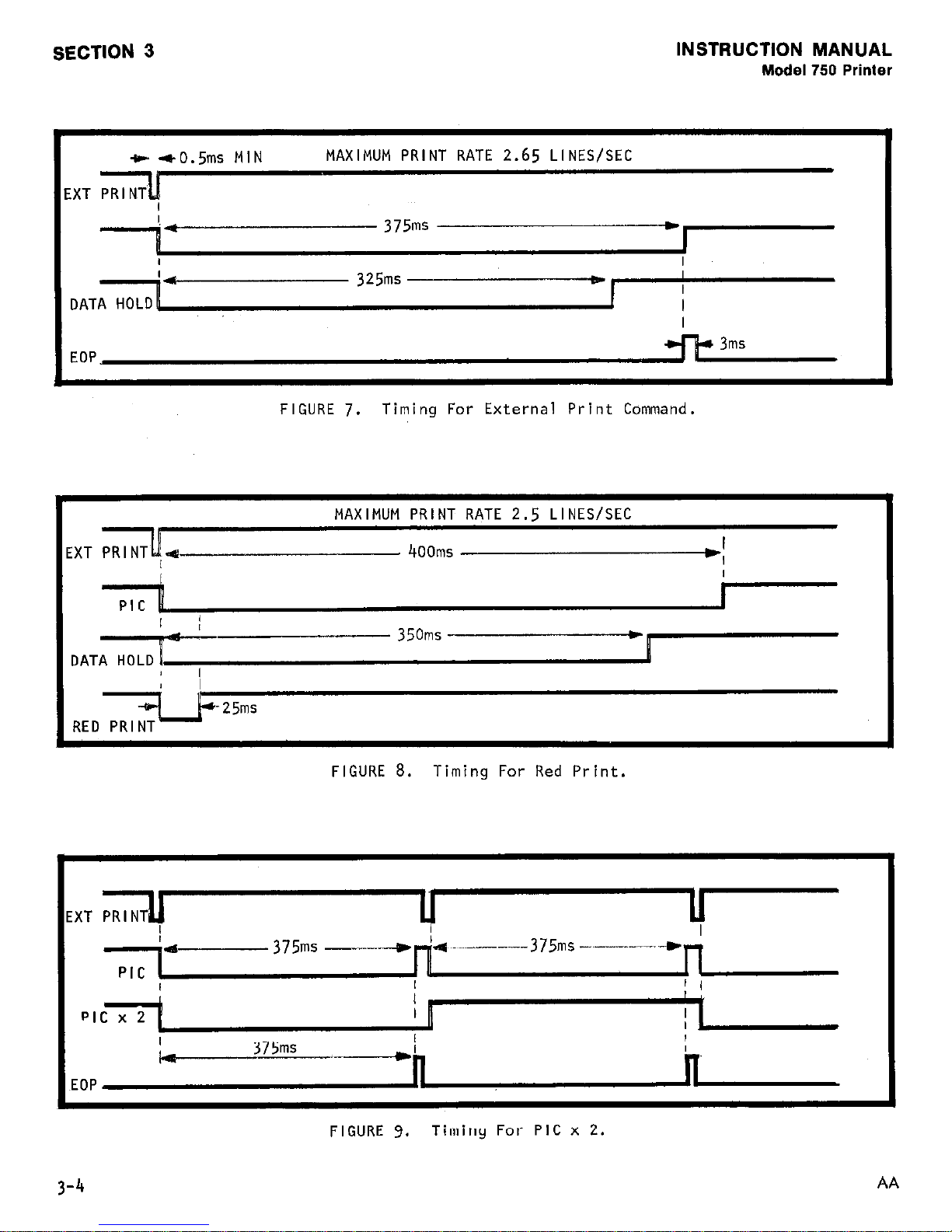
EXTERNAL PRINT Command (Pin 42).
An input transition from Logic "0" to Logic
"I" causes a print command in the Model 750.
Sinking current for Logic "0" is 4.2
milliamperes.
See Figure 7 for timing considerations.
3.
RED. (Pin 44) This input requires a Logic
"0" to cause the Model 750 to print
in "red". This feature may be used to indicate an overload condition on the digital
measurin,g instrument.
The RED input is level sensitive with a minimum duration of 25
milliseconds at Logic "0" from the start of PRINT cycle. See Figure 8 for timing
considerations. Sinking current for Logic "0" is 2.6 milliamperes.
TABLE
3-2.
I
'in No. Function Pin No.
I
2
z
2
is
9
IO
II
:;
I4
15
I6
1;
19
7.0
21
22
2';
25
P
n Identification
l-l
2-l
1-2
2-2
l-4
2-4
l-8
2-8
3-l
4-l
3-2
4-2
2:;
3-8
4-8
2:;
2:;
2:;
2:;
7-I
"CONNECTOR A"
26
27
28
29
;:
2:
47
48
49
50
Function
=
8-l
7-2
8-2
7-4
8-4
7-8
8-8
9-l
IO-I
9-2
IO-2
9-4
IO-4
9-8
10-8
6-DP
EXTERNAL PRINT
7-DP
RED PRINT
8-DP
COMMON
3-DP
+5v
IO-DP
DATA HOLD
AA
3-3
Page 18
SECTION 3
INSTRUCTION MANUAL
Model 750 Printer
e 40.5ms MIN
MAXIMUM PRINT RATE
2.65
LINES/SEC
I
I
- 375ms
I
I
I_
325ms
I
I
DATA HOLD
I
I
I
EOP
FIGURE
7.
Timing For External Print Command.
MAXIMUM PRINT RATE 2.5 LINES/SEC
II
EXT PRINT';- 400ms
w'
I
PIG
DATA+
I
- 350ms
1
I
-25ms
FIGURE 8. Timing For Red Print.
EXT PRINT
u
I
4
I
--~.--375 ms-..- ----.*
I
!
k
375ms
I
EOP
n
FIGURE 9.
Timing For PIC x 2.
AA
Page 19
INSTRUCTION MANUAL
Model 750 Printer
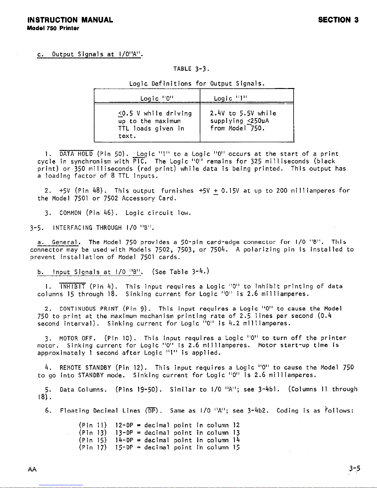
c. Output Signals at I/O"A".
TABLE 3-3.
Logic Definitions for Output Signals.
Logic "0" Logic "1"
-
0.5 V while driving
2.4V to 5.5V while
up to the maximum
supplying 250uA
TTL loads given in
from Model 750.
text.
1.
DATA HOLD (Pin 50). &ic "1" to a Logic "0" occurs at the start of a print
cycle in synchronism with PIC.
The Logic "0" remains for 325 milliseconds (black
print) or 350 milliseconds (red print) while data is being printed. This output has
a loading factor of 8 TTL inputs.
2. +5V (Pin 48). This output furnishes +5V + 0.15V at up to 200 milliamperes for
the Model 7501 or 7502 Accessory Card.
3.
COMMON (Pin 46). Logic circuit low.
3-5.
INTERFACING THROUGH I/O "B".
General. The Model 750 provides a 50-pin card-edge connector for I/O "B". This
co:nector may be used,with Models 7502, 7503, or 7504.
A polarizing pin is installed to
prevent installation of Model 7501 cards.
b. Input Signals at l/O "6". (See Table 3-4.)
I. INHIBIT (Pin 4). This input requires a Logic
"0" to inhibit printing of data
columns 15 through 18.
Sinking current for Logic "0" is 2.6 milliamperes.
CONTINUOUS PRINT (Pin 9)
This input requires a Logic "0" to cause the Model
75i*to print at the maximum mechanism printing rate of 2.5 lines per second (0.4
second interval). Sinking current for Logic "0" is 4.2 milliamperes.
3.
MOTOR OFF. (Pin 10).
This input requires a Logic
"0" to turn off the printer
motor.
Sinking current for Logic "0" is 2.6 milliamperes. Motor start-up time is
approximately 1 second after Logic "1" is applied.
4.
REMOTE STANDBY (Pin 12). This input requires a Logic "0" to cause the Model 750
to go into STANDBY mode.
Sinking current for Logic "0" is 2.6 milliamperes.
18;:
Data Columns. (Pins 19-50).
Similar to I/O "A"; see 3-4bl.
(Columns 11 through
6. Floating Decimal Lines (iiTi). Same as I/O "A"; see 3-4b2. Coding is as follows:
(Pin 11) 12-DP = decimal point in column 12
(Pin 13) 13-DP = decimal point in column 13
(Pin 15) 14-DP = decimal point in column 14
(Pin 17) 15-DP = decimal point ih column 15
Page 20
~EECT~ON 3
INSTRUCTION MANUA~L
Model 750 Prlf%&
C.
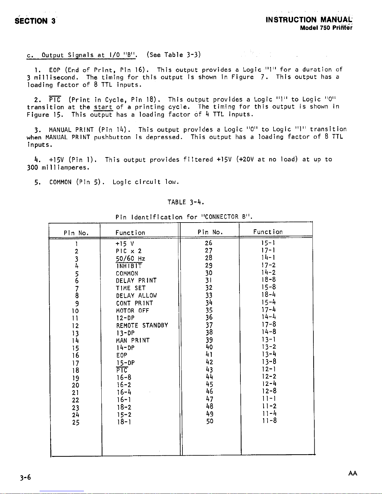
Output Signals at I/O "B".
(See Table 3-3)
1.
EOP (End of Print, Pin 16). This output provides a Logic "1" for a duration of
3 millisecond. The timing for this output is shown in Figure 7.
This output has a
loading factor of 8 TTL inputs.
2.
PIG (Print in Cycle, Pin 18). This output provides a Logic "1" to Logic "0"
transition at the start of a printing cycle. The timing for this output is shown in
Figure 15. This output has a loading factor of 4 TTL inputs.
3.
MANUAL PRINT (Pin 14). This output provides a Logic "0" to Logic "I" transition
when MANUAL PRINT pushbutton is depressed. This output has a loading factor of 8 TTL
inputs.
4.
+15V (Pin 1). This output provides filtered +15V (+2OV at no load) at up to
300 milliamperes.
5.
COMMON (Pin 5).
Logic circuit low.
TABLE 3-4.
Pin
Identification for "CONNECTOR B".
.., .--..-.. .---.-.. .-. ..~...~.~~~~
Pin No. Function
Pin No.
1 +15 v
z
PIG
50/l
mi
i’6
17
18
19
20
21
22
23
24
25
COMMON
DELAY PRINT
TIME SET
DELAY ALLOW
CONT PRINT
MOTOR OFF
12-DP
REMOTE STANDBY
13-DP
MAN PRINT
14-DP
EOP
15-DP
PIG
16-8
16-2
16-4
16-1
18-2
15-2
18-l
:e
14-2
18-8
32
15-8
18-4
15-4
;2
1z:::
;i
;;I;
iz
13-l
13-2
41
13-4
13-8
::
12-l
44
12-2
12-4
12-8
II-1
;i
II-2
49
11-4
50
11-8
3-6
AA
Page 21
INSTRUCTION MANUAL
Model 750 Printer
SECTION 3
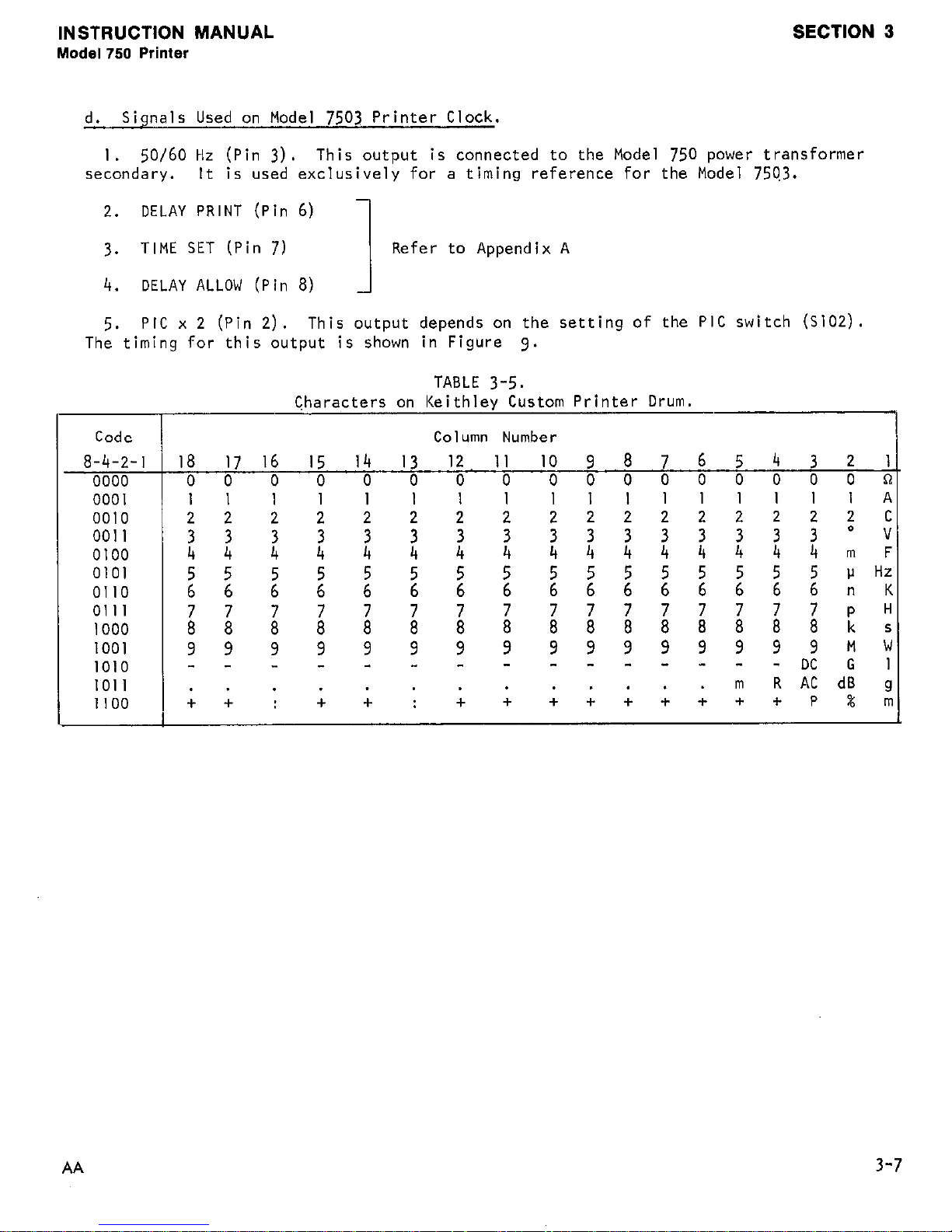
d.
Signals Used on Model
7503
Printer Clock.
I.
SO/60 Hz (Pin
3).
This output is connected to the Model 750 power transformer
secondary. It is used exclusively for a timing reference for the Model
750.3.
2.
DELAY PRINT (Pin 6)
3.
TIME SET (Pin 7)
I
Refer to Appendix A
4.
DELAY ALLOW (Pin 8)
5.
PIC x 2 (Pin 2).
This output depends on the setting of the PIC switch (SlO2).
The timing for this output is shown in Figure 8.
TABLE
3-5.
Characters on Keithlev Custom Printer Drum.
Code
I
Column Number
8-4-2-l j 18
17 16 15 14
13 12
11 IO 9
8 7 6 5 4 3 2
1
0000 100 0 0 0 0 0 0 000000000n
0001
0010
0011
0100
0101
0110
0111
1000
1001
1010
1011
1100 (
11 11 11 1 I lllllllllA
22 2 2 2 2 2 2 222222222c
; i z 2 2 2 z z ;;;;;;33-
4 4
m F
2
56
2 2 2 2 ;
5 6 55555555vHz 6 6 6 6 6 6 6 6
n K
ii
i ;: i i ll i ;
7 8 7 8 7 8 7 8 8 7 7 8 7 8 7 8
p k H
s
99 9 9 9 9 9 9
_ _ _ _ - - - -
9 9 9 9 9 9 “,2
- - - - - -
My
G
. . . . . . . . . . . . . m
R AC dB g
++:
+
+ :
+
+ + + + + + + + P % rr
AA
3-7
Page 22
SECTION 3
INSTRUCTION MANUAL
Model 750 Printer
ROL
* FAI
AF
.D
'ER
PAPER
CAUTION
LINE VOLTAGE IS A SHOCK HAZARD
WHEN TOP COVER IS REMOVED.
FIGURE 10.
Top View of Chassis Showing Roll and Fanfold Paper Installed.
Page 23
INSTRUCTION MANUAL
Model 750 Printer
SECTION 4
SECTION 4. ACCESSORIES.
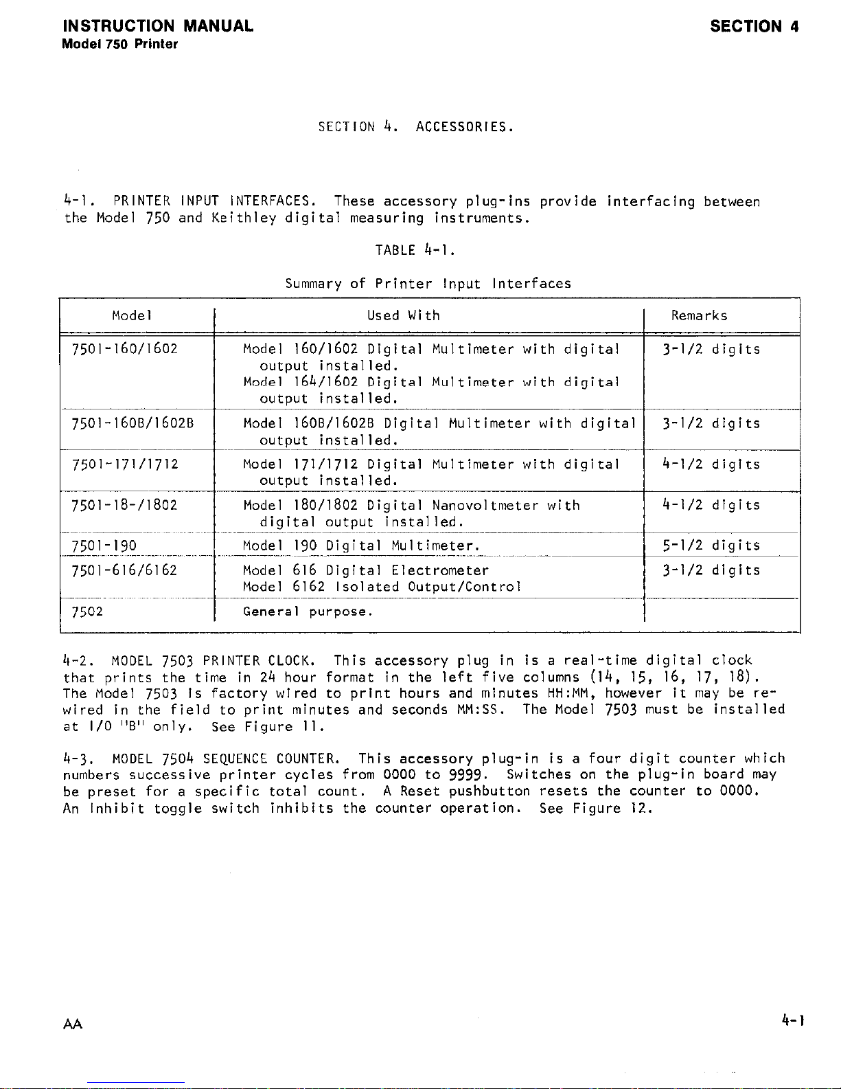
4-l. PRINTER INPUT INTERFACES.
These accessory plug-ins provide interfacing between
the Model 750 and Keithley digital measuring instruments.
TABLE 4-1.
Model
7501-160/1602
Summary of Printer Input Interfaces
Used With Remarks
Mode1 160/1602 Digital Multimeter with digital ) 3-l/2 digits
I
output installed.
Model 164/1602 Digital Multimeter with digital
I
I I
output installed.
I
7501-16OB/l602B Model 1608/1602B Digital Multimeter with digital 3-l/2 digits
outcut installed. I
Model 171/1712 Digital Multimeter with digital
Model 190 Diqital Multimeter. 1 5-l/2 diqits 1
7501-616/6162
I
Model 616 Digital Electrometer
3-l/2 digits
Model 6162 Isolated Outout/Control I
7502
I
General purpose.
I
I
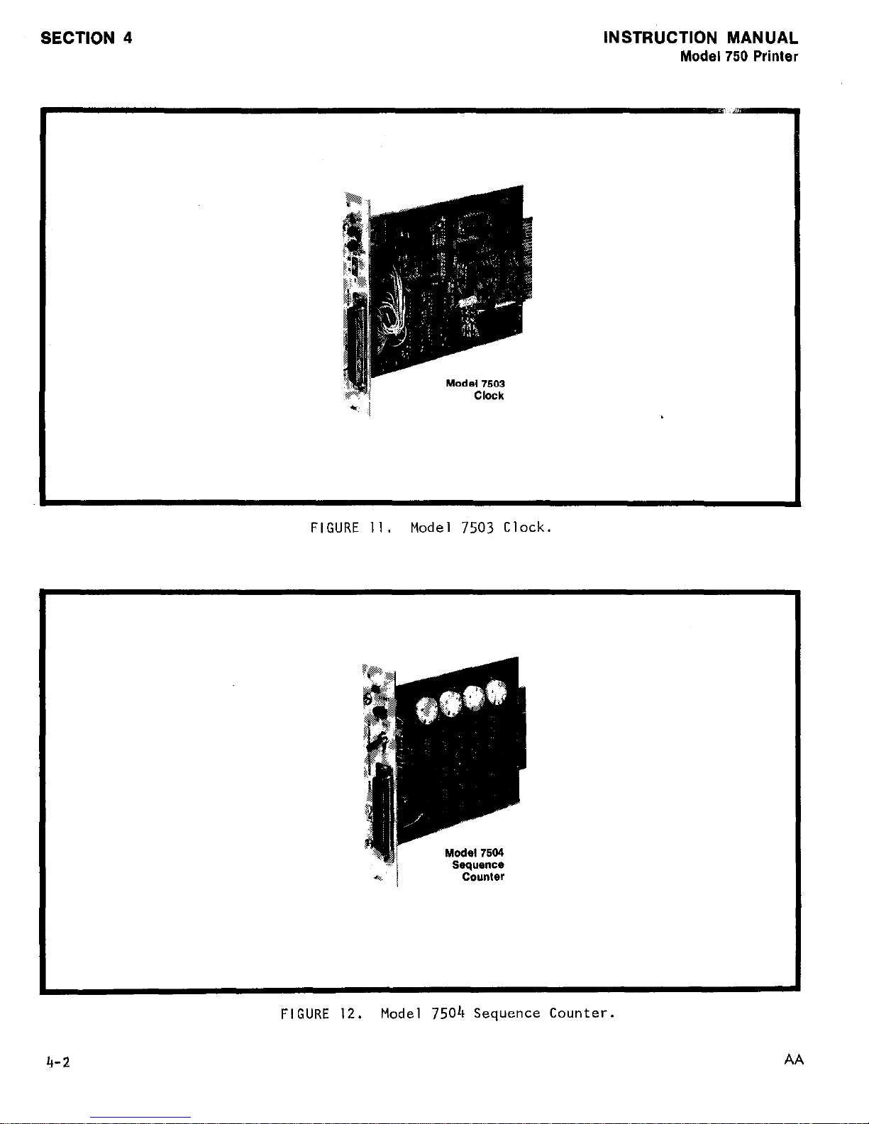
4-2. MODEL 7503 PRINTER CLOCK. This accessory plug in is a real-time digital clock
that prints the time in 24 hour format in the left five columns (14, 15, 16, 17, 18).
The Model 7503 is factory wired to print hours and minutes HH:MM, however it may be rewired in the field to print minutes and seconds MM:SS.
The Model 7503 must be installed
at I/O "B" only.
See Figure 11.
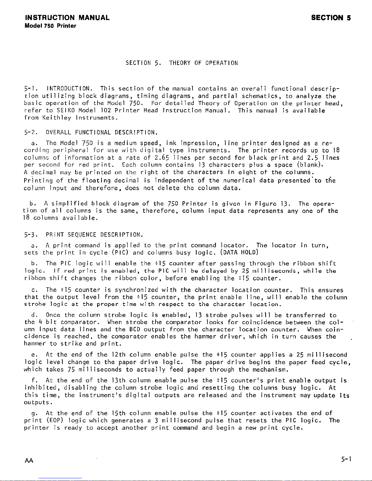
4-3.
MODEL 7504 SEQUENCE COUNTER.
This accessory plug-in is a four digit counter which
numbers successive printer cycles from 0000 to 9999.
Switches on the plug-in board may
be preset for a specific total count.
A Reset pushbutton resets the counter to 0000.
An Inhibit toggle switch inhibits the counter operation. See Figure 12.
AA
4-l
Page 24
SECTION 4
INSTRUCTION MANUAL
Model 750 Printer
FIGURE 11.
Model
7503
Clock.
FIGURE 12.
Model 7504 Sequence Counter.
4-2
Page 25
INSTRUCTION MANUAL
Model 750 Printer
SECTION 5.
THEORY OF OPERATION
SECTION 5
5-l.
INTRODUCTION.
This section of the manual contains an overall functional descr,iption utilizing block diagrams, timing diagrams, and partial schematics, to analyze the
basic operation of the Model 750. For detailed Theory of Operation on the printer head,
refer to SEIKO Model 102 Printer Head Instruction Manual.
This manual is available
from Keithley Instruments.
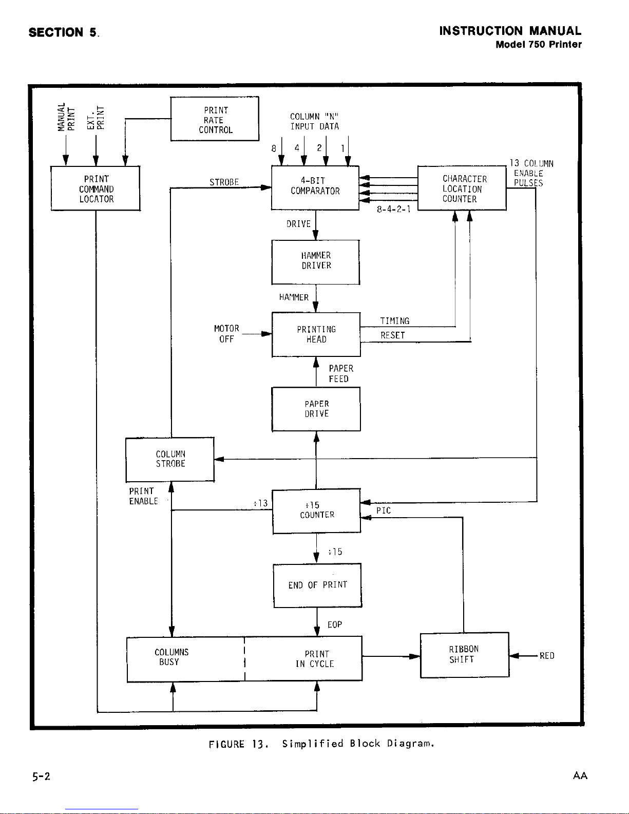
5-2. OVERALL FUNCTIONAL DESCRIPTION.
a.
The Model 750 is a medium speed, ink impression,
line printer designed as a re-
cording peripheral for "se with digital type instruments.
The printer records up to I8
columns of information at a rate of 2.65 lines per second for black print and 2.5 lines
per second for red print. Each column contains 13 characters plus a space (blank).
A decimal may be printed on the right of the characters in eight of the columns.
Prjnting of the floating decimal is independent of the numerical data presented'to the
column input and therefore, does not delete the column data.
b.
A simplified block diagram of the 750 Printer is given in Figure 13. The opera-
tion of all columns is the same, therefore,
column input data represents any one of the
18 columns available.
5-3.
PRINT SEQUENCE DESCRIPTION.
a. A print command is applied to the print command locator. The locator in turn,
sets the print in cycle (PIG) and columns busy logic. (DATA HOLD)
b. The PIC logic will enable the $15 counter after passing through the ribbon shift
logic. If red print is enabled, the PIC will be delayed by
25
milliseconds, while the
ribbon shift changes the ribbon color,
before enabling the $15 counter.
C.
The +I5 counter is synchronized with the character location counter.
This ensures
that the output level from the $15 counter,
the print enable line, will enable the column
strobe logic at the proper time with respect to the character location.
d.
Once the column strobe logic is enabled, I3 strobe pulses will be transferred to
the 4 bit comparator. When strobe the comparator looks for coincidence between the column input data lines and the BCD output from the character location counter.
When coincidence is reached, the comparator enables the hammer driver, which in turn causes the
hammer to strike and print.
e.
At the end of the 12th column enable pulse the tl5 counter applies a 25 millisecond
logic level change to the paper drive logic.
The paper drive begins the paper feed cycle,
which takes 75 milliseconds to actually feed paper through the mechanism.
f.
At the end of the 13th column enable pulse the ~15 counter's print enable output is
inhibited, disabling the column strobe logic and resetting the columns busy logic. At
this time,
the instrument's digital outputs are released and the instrument may update its
outputs.
9.
At the end of the 15th column enable pulse the $15 counter activates the end of
print (EOP) logic which generates a 3 millisecond pulse that resets the PIC logic. The
printer is ready to accept another print command and begin a new print cycle.
AA
5-1
Page 26
SECTION 5.
INSTRUCTION MANUAL
Model 750 Printer
s+ +
SE
<z
----I
PRINT
RATE
C"NTR"l
I
COLUMN "N"
INPUT DATA
HAMMER
DRIVER
TIMING
MOTOR
PRINTING
J
OFF -
HEAD
RESET
L
I
HAMMER
4
COLUMN
STROBE
PRINT
ENABLE
$13
$15
4
COUNTER
PIG
END OF PRINT END OF PRINT
i
I
I
I 1
I
t
I
4EOP , 1 ,
COLUMNS
I
PRINT
BUSY
I
RED
IN CYCLE
I
A
4
FIGURE
13.
Simplified Block Diagram.
5-2
AA
Page 27
INSTRUCTION MANUAL
Model 750 Printer
SECTION 6.
MAINTENANCE
SECTION 6
6-l. GENERAL. This section contains information necessary to verify performance of the
entire instrument, perform simple maintenance on the printer mechanism, troubleshoot and
repair the control electronics and switching. Extensive maintenance and repair procedures
are available separately in the
Seiko Instruction Manual for the Modei! 102 Printer
Mechanism.
No calibration of electronic circuitry is required.
6-2. MECHANISM - SIMPLE MAINTENANCE PROCEDURES.
a.
Paper Replacement.
I. How to Install Fan-Fold Paper.
a)
Pull out front panel by grasping handle on front panel. Panel swings open as
shown in Figure 3.
b) Pull out paper tray.
C)
Place stack of fan-fold paper in pull-out tray as shown in Figure 4. Be cer-
tain the tray is aligned so that the metal tab is in the front.
d) Lift and fold-out the top two layers of paper. This provides a leader for
loading the tape in the print mechanism.
4
Hold the pack so that the leader is pointing away from the printer and slide
the tray into the tape drawer.
When properly installed,
tray should be just behind the front panel.
the front end of the paper
f) Proceed to Paper Feed Instructions in paragraph a3.
2. How to Install Roll-Type Paper.
NOTE
Roll should not exceed Z-3/4 inches in diameter.
4
Remove top cover by unscrewing the four Phillips head screws.
b)
Install the roll paper on the roller pin located as shown in Figure IO.
c)
Pull out front panel by grasping handle on front panel.
shown in Figure 3.
Panel swings open as
d) Grasp the paper roll in one hand and pull out a twelve inch leader.
4
Point the leader t&ward the front panel on the printer and, position the paper
roll so that the leader is being pulled off the bottom of the roll.
f) Slide the paper roll into the roll fixture as shown in Figure IO.
g) Feed the free end of paper under mechani.sm. until it protrudes at the front
.panel. (See Figure 4.)
h) Replace the top cover.
i)
Proceed to Paper Feed Instructions in paragriph.a3.
3.
Paper Feed Instructions.
a)
Release the RUN pushbutton to place the Model 750 in "Standby".
AA
6-1
Page 28
SECTION 6
INSTRUCTION MANUAL
Model 750 Printer
b) Apply power to the instrument by depressing the front panel POWER pushbutton.
d
Install paper (either fan-fold or roll-type as in preceeding paragraphs).
d) Locate the arrow on the front of printer mechanism.
e)
Feed paper under the clip, over the arrow, and into printer mechanism as shown
in Figure
5.
f) Depress PAPER FEED pushbutton until printer begins to pull paper through mech-
ansim.
g) As the paper appears at the top of printer,
guide the paper under the cutting
bar.
h) Allow about 2 extra inches of paper to feed,
then release PAPER FEED button.
i) Tear off paper flush with cutting bar.
j) Replace front panel by inserting right side and snapping into place.
k) Test for smooth paper advance by depressing PAPER FEED button until a few
inches of paper are advanced.
b. Ribbon Replacemerit.
I.
Pull out front panel by grasping handle on front panel.
2.
On the printer mechanism, locate and,push down the Detecting Lever of both spool
shafts (see Figure
5).
3.
Carefully remove old ribbon spools from shafts.
4. Remove old ribbon from feed guides and from under hammer.
5.
Separate the new ribbon spools and lay them on a flat surface with their "finger"
side down.
6.
Refer to Figure 6 and ensure that the new ribbon is properly threaded on the
spools.
7.
On the printer mechanism, locate and push down the Detecting Lever on left hand
spool shaft,
slide the spool onto the shaft making note of the proper threading direc-
tion shown in Figure 6.
a.
Unwind 6 or 0 inches of ribbon from the remaining spool, if necessary, and posi-
tion the ribbon over the feed guides as shown in Figure 6.
9.
Depress the detecting lever on the empty spool shaft and slip the second spool
onto the shaft.
Make sure that there are no twists in the ribbon.
c. Cleaning of Paper-Feed Compartment.
Periodic cleaning of Paper-feed compartment
is recommended to remove paper cuttings which may accumulate.
Suggested cleaning inter-
val is after printing 10 rolls or 20 fan-fold packs or every 90 days.
I.
Apply a slight downward pressure on the cutting bar to unlock, then pull down.
2.
Remove the plate behind the cutting bar to gain access to the printer drum and
paper feed mechanism.
3.
Clean mechanism using brush.
4. Replace plate.
5.
Snap cutting bar back into place.
6-2
AA
Page 29
INSTRUCTION MANUAL
Model 750 Printer
SECTION 6
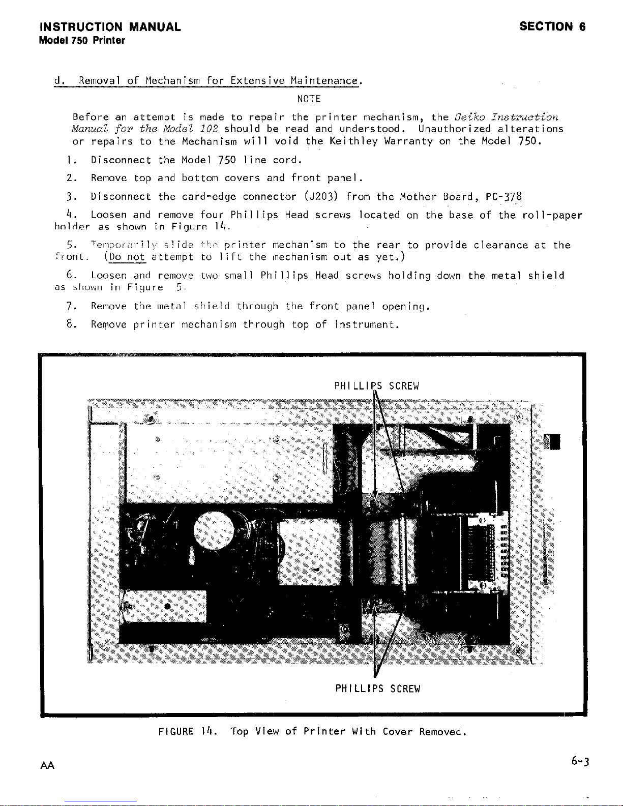
d. Removal of Mechanism for Extensive Maintenance.
NOTE
Before an attempt is made to repair the printer mechanism, the
Seiko Instruction
Manual,
for
the Mode2
102 should be read and understood. Unauthorized alterations
or repairs to the Mechanism will void the Keithley Warranty on the Model 750.
I.
Disconnect the Model 750 line cord.
2. Remove top and bottom covers and front panel.
3.
Disconnect the card-edge connector (J203) from the Mother Board, PC-378
4.
Loosen and remove four Phillips Head screws located on the base of the roll-paper
holder as shown in Figure I4
i-,-&t. (D
TempoiI,iril\. s!ide :~I-~(- printer mechanism to the rear to provide clearance at the
o not attemp't to Ii~Tt the (mechanism out as yet.)
6. Loosen and remove tbwo small Phillips Head screws holding down the metal shield
as il?own in Figure
5 /,
7.
Remove the metal shield through the front panel opening.
8.
Remove printer mechanism through top of instrument.
PHILLIP_S SCREW
PHILLIPS SCREW
FIGURE 14.
Top View of Printer With Cover Removed.
6-3
Page 30
SECTION 6
e.
Cleaning of Mechanism.
INSTRUCTION MANUAL
Model 750 Printer
Use a small brush, vacuum cleaning device,
I.
and paper particles from the hammers, springs, and solenoid ratchets.
2. Use alcohol to remove grease from metal parts of the mechanism.
CAUTkON
Care should be taken if other solvents are used on the plastic parts, since solvents
such.as tri-chloroethylene and ketone may cause damage.
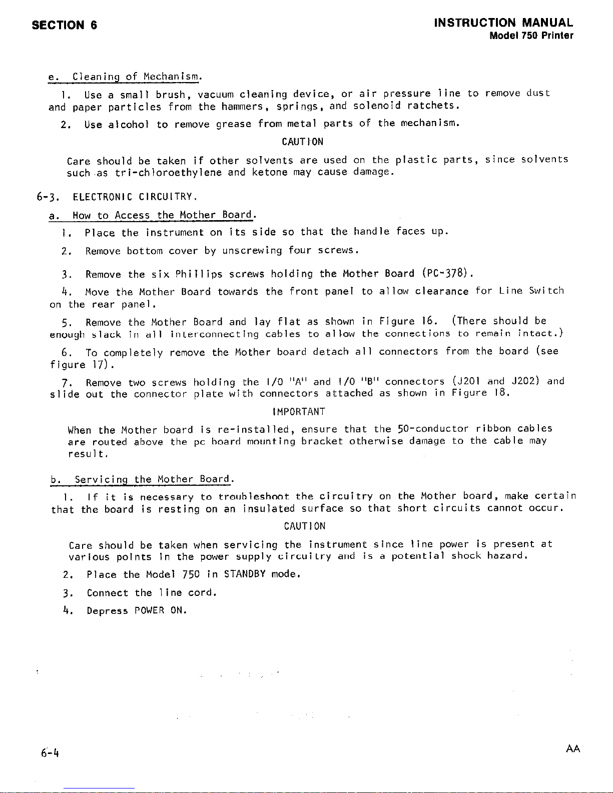
6-3. ELECTRONIC CIRCUITRY.
a. How to Access the Mother Board.
1. Place the instrument on its side so that the handle faces up.
Remove bottom cover by unscrewing four screws.
2.
Remove the six Phillips screws holding the Mother Board (PC-37~8).
3.
4. Move the Mother Board towards the front panel to allow clearance for Line Switch
on the rear panel.
Remove the Mother Board and lay flat as shown in Figure 16.
5.
enough slack in all interconnecting cables to allow the connections to remain intact.)
6.
To completely remove the Mother board detach all connectors from the board (see
figure 17).
Remove two screws hold~ing the I/O "A" and l/O "5" connectors (JZOI and J202) and
7.
slide out the connector plate with connectors attached as shown in Figure 18.
or air pressure line to remove dust
(There should be
IMPORTANT
When the Mother board is re-installed, ensure that the 50-conductor ribbon cables
are routed above the pc board mounting bracket otherwise damage to the cable may
result.
b. Servicing the Mother Board.
If it is necessary to troubleshoot the circuitry on the Mother board, make certain
I.
that the board is resting on an insulated surface so that short circuits cannot occur.
CAUTION
Care should be taken when servicing the instrument since line power is present at
various points in the power supply circuitry and is a potential shock hazard.
Place the Model 750 in STANDBY mode.
2.
Connect the line cord.
3.
4. Depress POWER ON.
6’-4
AA
Page 31

INSTRUCTION MANUAL
Model750 Printer
SECTION 6
AA
FIGURE
J106
J'04~ioJ~~ J103
FIGURE 16.
Assembly of Chassis.
15.
Q
'
Mother Board Assembly.
6-5
Page 32

SECTION 6
INSTRUCTION MANUAL
Model 750 Printer
PHILLIP
FIGURE
17.
Assembly of Connector Board.
C.
Troubleshooting Procedures.
The following information is designed to aid in lo-
cating problems within the electronic circuitry.
Extensive repairs should be performed
only by authorized factory repair facilities.
I.
Set the Line Voltage switch to the appropriate position.
2. Check the fuse for proper rating.
3.
Set the Model
750
to STANDBY mode.
4.
Partially remove the Mother board as described in paragraph
6-3a.
5.
Connect the line cord.
6.
Depress POWER ON.
7.
Set Print Interval control to EXT.
8.
Follow the troubleshooting procedure given in Table
6-2.
NOTE
Test point A should be used as a common reference point for all measurements.
6-6
AA
Page 33

INSTRUCTION MANUAL
Model 750 Printer
SECTION 6
TABLE
6-1.
Recommended Test Equipment
1
Item Description
Specification Mfr. Model
A
Digital Multimeter O.lV - 1OOOV DC, CO.l%
KI
168
B Oscilloscope
DC coupled, 100 1.1s sweep
Tektronix
560
TABLE
6-2.
Troubleshooting Guide For Model 750 Circuitry.
_TROUBLE CHECK
OPERATION
RESULT PROBLEM
lot Printing Test Point B STANDBY
+15v
Rectifiers open
Test Point C STANDBY
+5v
Regulator faulty
Test Point D STANDBY
5ms low going pulse Rate Control UlO2
.Is interval faulty
Test Point E DEPRESS E. HOLD IOms low going pulse
UlO4 or U103 faulty
MANUAL PRINT
1s interval
Test Point F STANDBY
.3ms low going pulse Reset or Timing Pulse
375ms interval shaper circuit faulty
Test Point G STANDBY
18ms high, Ims low
Ul13 faulty, timing
pulse train
pulse shaper circuit
faulty
Test Poing H DEPRESS PRINT Above Pulse Train for U122 faulty
375ms
Test Point J DEPRESS PRINT 375ms low going
If held lo EOP generat-
(PIG)
lC?"C?l
or faulty.
If held
high Ulll faulty
Test Point K DEPRESS PRINT 3ms
low
going pulse
EOP generator faulty
(EOP)
.Is interval
(UlO8, Ul25,
or
Ul24)
Test Point L DEPRESS PRINT Pulse train 32.5ms
~120 or ~116 faulty
Test Point M DEPRESS PRINT Pulse train 325ms
UIIO or Ul20 faulty
Test Point N DEPRESS PRINT Pulse train 325ms
u118 faulty
lo Paper
Test Point P DEPRESS FEED
25ms low pulse IOOms u119 faulty
'eed
time interval
DEPRESS PRINT 25ms low pulse Is
~106, ~116 or U124
interval faulty
NOTE
Test point locations can be found
in Figure 38 in Appendix F.
AA
6-7
Page 34

SECTION 6
INSTRUCTION MANUAL
Model
750 Printer
CAUTION
To
ensure the integrity of the chassis to earth ground connection only a Keithley
part number CO-7 line cord should be used for replacement.
If a different line cord
is used ensure that the wiring polarity is the same as shown in the following dia-
gram.
NEMA
5-15p
WHiTE
WHITE
6-8
AA
Page 35

INSTRUCTION MANUAL
Model 750 Printer
SECTION 7.
REPLACEABLE PARTS
SECTION 7
7-l.
GENERAL. This section contains information for ordering replacement parts. The
parts list is arranged in alphabetical order of their Circuit Designations.
7-2.
ORDERING INFORMATION.
To place an order or to obtain information concerning
replacement parts,
contact your Keithley representative or the factory. See the inside
front cover of the catalog for addresses. When ordering,
include the following informa-
tion.
a.
Instrument Model Number
b. Instrument Serial Number
C.
Part Description
d. Circuit Designation (if applicable)
e.
Keithley Part Number
7-3.
SCHEMATICS.
a. No. 27226E:
Logic and Power Supply (~~-378).
Describes the printer controls,
logic, and power supply.
b.
No. 27227E: Multiplex/Driver circuit (PC-378).
Describes the printer driver cir-
cuits and the I/O connector pinout.
c. No. 272436:
Describes the pushbutton switching assembly (PC-380).
d.
No. 27245E: 7503 Digital Clock.
Describes accessory Clock plug-in.
e. No. 27246D:
7504 Sequence Counter.
Describes the accessory Sequence Counter.
f.
No. 27244D:
7502 General Purpose Plug-in.
7-4.
REPLACEABLE PARTS LIST.
The following parts list includes the Model 750, 7503,
and 7504.
a. Model 750:
Parts are located on PC-378 and PC-380.
b. Model 7503:
Parts are located on PC-374.
c. Model 7504: Parts are located on ~~-385.
7-1
Page 36

SECTION 7
CAPACITORS
Schematic 27226E, Logic and Power Supply (PC-378)
Circuit Mfr. Mfr. Keithley
Desig. Description Code Desig. Part No.
Cl01
Cl02
Cl03
Cl04
Cl05
1.0 pF, 2OV, ETT.
5.6 pF, 2OV, IO%, ETT
1.0 pF, 2OV, IO%, ETT
10 ,,F, 2OV, IO%, ETT. .....
3300 pF, 5OOV, 20%, CerD.
.......
.....
.....
...
COMPI TSDl20105A C-204-l.OM
COMPI
COMPI
COMPI
ERIE 801-25~0-332~ C-22-3300P
TD502056620
TSDl20105A C-204-l.OM
TSD120105A C-204-IOM
INSTRUCTION MANUAL
C-l79-5.6M
Model 750 Printer
Qty .
3
1
. .
. .
2
cl06
Cl07
cl08
Cl09
Cl10
Clll
Cl12
Cl13
Cl14
Cl15
cl16
Cl17
cl18
Cl19
Cl20
Cl21
Cl22
Cl23
Cl24
Cl25
Cl26
Cl27
cl28
Cl29
Cl30
Cl31
22 I-IF, 2OV, ETT
10 UF, 2OV, IO%, ETT.
0.01 pF, Ibv, CerD.
0.01 ~JF, l6~, CerD.
IO uF, 2OV, lo%, ETT.
I.0 uF, 16v, CerD
4.7 uF, 2OV, ETT.
0.047 uF, 25OV, MtF
0.047 pF, 25OV, MtF
0.047 uF, 250V;MtF
0.047 ~.IF, 25OV, MtF
2.2 uF, 2OV, ETT.
0.047 I.IF, 25OV, MtF
0.1 uF, 16v, CerD
0.047 nF, 25OV, MtF
1000 lip, 25v, EMC
780 uF, 3OV, EAL.
1.0 nF, 35V, ETT.
IO I-IF, 2OV, IO%, ETT.
3300 pF, 5OOV, 20%, CerD.
I.0 pF, 5OV, CerF
0.01 uF. 16~. CerD.
0.01 uF,
0.01 liF,
0.01 IJF,
0.01 pF,
,
6~; CerD. .....
6v, CerD. .....
6v, CerD. .....
6v, CerD. .....
........
.....
......
......
.....
.......
.......
......
......
......
......
.......
......
.......
......
.......
.......
.......
.....
.......
......
...
COMPI
COMPI TSDl20106A C-204-IOM
CENLB ~~16-104 C-238-O.OlM
CENLB
COMPI
CENLB TSDl20105A C-204-l.OM
COMPI
AMPRX
AMPRX
AMPRX
AMPRX
COMPI
AMPRX
CENLB ~~16-104 C-238-O.lM
AMPRX
AMPRX
GE
KEMET
COMPI TSDl20106A
ERIE
ERIE
CENLB u1<16-104
CENLB u1<16-lo4
: CENLB u1<16-104
. CENLB ~~16-104
. CENLB u1<16-lo4
TD12022620
~~16-104
TSDl20106A C-204-IOM
TDI-20-475-20
C280AE/P47K C-l78-0.047M
C280AE/P47K
C280AE/P47K C-l78-0.047M
C280AE/P47K
TDI-20-225-20
C280AE/P47K C-178-0.047M
C280AE/P47K C-l78-.047M
ETl20X025A03 C-160-IOOOM
86~-148~ C-263-7800M
KlE35
801-~5~0-332~
8131050651-105~
C-179-22M
C-238-O.OlM
C-l79-4.7M
C-l78-0.047M
C-l78-0.047M
C-l79-2.2M
C-170-l.OM
C-204-IOM
C-22-3300P
C-237-l.OM
C-238-O.OlM
~-238-0.01~
C-238-O.OlM
C-238-O.OlM
C-238-O.OlM
I
2
35
. .
I
. .
z
. *
. .
. *
1
. .
. .
. .
I
I
I
I
. .
I
. .
. .
. .
. .
. .
Cl32
Cl33
Cl34
Cl35
Cl36
Cl37
Cl38
7-2
0.01 nF, 1 6v, CerD. .....
0.01 uF, 1 6v, CerD. .....
0.01 pF, l6v, CerD. . . . . . . . CENLB u1<16-lo4
0.01 uF,
0.01 pF, 6v, CerD. .....
0.01 pF, 6v, CerD. .....
0.01 pF, I~V, CerD. .....
6v, CerD. .....
CENLB ~~16-104
CENLB u1(16-lo4
CENLB ~~16-104
CENLB u1<16-lo4
CENLB ~~16-104
CENLB ~~16-104
C-238-O.OlM
C-238-O.OlM
C-238-O.OlM
C-238-O.OlM
C-238-O.OlM
C-238-O.OlM
~-238-0.01~
. .
. .
. .
. .
. *
. .
. .
AA
Page 37

INSTRUCTION MANUAL
Model 750 Printer
SECTION 7
CAPACITORS
Schematic 27227E, Multiplex/Driver Circuit (~~-278)
Circuit
Mfr. Mfr. Keithley
Desig. Description
Code
Desig. Part No.
Qtv.
c201
c202
C203
~204
C205
C206
~207
CL?08
czog
CZIO
c211
c212
c213
C214
c215
1~216
C217
~218
c21g
c220
C221
0.01 liF, l6~, CerD. . . . .
0.01 uF, l6v, CerD. . . . .
0.01 uF, l6v, CerD. . . . .
0.01 pF, I~v, CerD. , . . .
0.01 pF, I~v, CerD. . . . .
0.01 JJF, I~v, CerD. . . . .
0.01 uF, l6v, CerD. . . . .
0.01 ~.IF, I~v, CerD. . . . .
0.01 uF, I~V, CerD. . . . .
0.01 uF, I~V, CerD. . . . .
0.01 uF, I~V, CerD. . . . .
0.01 I-IF, I~V, CerD. . . . .
0.01 ~.IF, I~v, CerD. . . . .
0.01 IJF, I~v, CerD. . . . .
0.01 !JF, I~v, CerD. . . . .
0.01 uF, I~v, CerD. . . . .
0.01 uF, 16~, CerD. . . . .
0.01 !JF, I~v, CerD. . . . .
0.01 I-IF, I~v, CerD. . . . .
0.01 uF, I~v, CerD. . . . .
0.01 uF, I~v, CerD. . . . .
Schematic 27226E?
. . CENLB ~~16-104
CENLB ~~16-104
: : CENLB 1~~16-104
CENLB u1<16-lo4
: : CENLB ~~16-104
CENLB ~~16-104
: : CENLB ~~16-104
CENLB Ul<l6-104
: : CENLB ~~16-104
. .
CENLB ~~16-104
CENLB ~~16-104
: : CENLB ~16-104
. . CENLB ~~16-104
cENLB ~~16-104
: : CENLB ~~16-104
. .
CENLB ~~16-104
. . CENLB ~~16-104
. .
CENLB UK16-104
. . CENLB ~~16-104
CENLB ~~16-104
: : CENLB ~~16-104
DIODES
Logic & Power Supply
C-238-O.OlM
C-238-O.OlM
C-238-O.OlM
C-238-O.OlM
C-238-O.OlM
C-238-O.OlM
C-238-O.OlM
C-238-O.OlM
C-238-O.OlM
C-238-O.OlM
C-238-O.OlM
C-238-O.OlM
C-238-O.OlM
C-238-O.OlM
C-238-O.OlM
C-238-O.OlM
C-238-O.OlM
C-238-O.OlM
C-238-O.OlM
C-238-O.OlM
C-238-O.OlM
(PC-378)
. .
. .
. .
. .
. *
. .
* .
. .
. .
. .
. .
. .
. .
. .
. .
. .
. .
. .
* .
. .
. .
Circuit Mfr.
Mfr. Keithley
Desig.
Description
Code Desig. Part No.
Qty .
CRIOI Rectifier, 6A, 1OOV ....... MOT
MR751
RF-42
CR102 Rectifier, 6A, IOOV ....... MOT
MR751
RF-42 ..
CR103 Rectifier, 6A, IOOV ....... MOT
MR751
RF-42
..
CR104 Rectifier, 6A, 1OOV ....... MOT
MR751
RF-42
..
CR105 Rectifier, l.OA, 800~ ...... MOT 1~4006 RF-38
CR106 Rectifier, 75mA, 75V. ...... TEXAS IN914
RF-28
CR107 Rectifier, 75mA, 75V. ...... TEXAS IN914
RF-28 . .
CR108
Rectifier, 75mA, 75V. ...... TEXAS IN914 RF-28 ..
CR109
Rectifier, 75mA, 75V. ...... TEXAS IN914
RF-28
..
CRIIO
Rectifier, 75mA, 75V. ...... TEXAS IN914
RF-28
..
CRlll Rectifier, 75mA, 75V. ...... TEXAS IN914
RF-28 . .
CR112 Rectifier, 75mA, 75V. ...... TEXAS IN914
RF-28
..
CRII3 Rectifier, 75mA, 75V. ...... TEXAS IN914
RF-28
..
CR114 Rectifier, 75mA, 75V. ...... TEXAS IN914
RF-28 ..
FUSES
Circuit
Mfr. Mfr. Keithley
Desig. Description
Code
Desig.
Part No.
Qty .
FIOI (220V) Fuse, Slo-Blo, 3/8A, 250V FUSE MDL-3/8A
FU-I8 I
--
.(lOO-117V) Fuse, Slo-Blo, 3/4A,
250~. ............. FUSE MDL-3/4A
FU-19
1
AA
7-3
Page 38

SECTION 7
INSTRUCTION MANUAL
Model 750 Printer
CONNECTORS
Schematic 27226E, Logic E Power Supply (PC-378)
Circuit Mfr. Mfr. Keithley
Desig. Description
Code
Desig. Part No.
Qty .
JIOI 5-pins. . . . . . . . . . . . . . . . MOLEX 2139-5 CS-287-5 I
J102 It-pins. . . . . . . . . . . . . . . . MOLEX 2139-4
CS-287-4
I
JlO3 3-pins. . , . . . . . . . . . . . . . MOLEX 2139-3 ~5-287-3
I
PlOl S-pin , . , . . . . . . . . . . . . . MOLEX A-23pl-5A
~~-288-5 I
PI02
4-pin . . . . . . . . . . . . . . . . MOLEX A-23vl-4A
~~-288-4
2
PI03 3-pin + . . , . . . . . . . . . . . . MOLEX A-23vl-3A cs-288-3
I
PI04 4-pin . . . , , . . . . . . . . , . . MOLEX A-23vl-4A CS-288-4
. *
PI05 Power Receptacle. , . . . . , . . . . S-C EAC-301 CS-254 I
~106 2-pin . . . . . . . . . . . . . . . . MOLEX A-23vl-2A
CS-288-2
I
CONNECTORS
Schematic 27227E, Multiplex/Driver Circuit (~~-378)
Circuit Mfr.
Mfr. Keithley
Desig. Description
Code Desig.
Part No.
Qtv.
J201
J202
J203
J3Ol
J302
P2Ol
P202
P203
Cable . . . . . . . . . . . . . . . . . KI --
750-24B(set of 2) I
Cable................KI --
__
Part of printer mechanism . . . . . . --
--
__
4-pin . . . . . . . . . . . . . . . . MOLEX 2139-4
cs-287-4
I
2-pin . . . , , , . . . . . . . . . . MOLEX 2139-2 CS-275
I
Not Used. . . . . . . . . . . . . . . -- --
__
Not Used. . . . . . . . . . . . . . . --
--
__
Part of ~~-378. , . . . . . ., . . . . -- --
-_
TRANSISTORS
Schematic 27226E, Logic & Power Supply (~~-378)
Circuit Mfr.
Mfr. Keithley
Desig.
Description
Code Desig. Part No.
Qtv.
QIOI NPN Silicon, TO-92 Case . . . . . . . FAIR
2N3903
TG-49
3
Q102
NPN Silicon, TO-92 Case . . . . . . . FAIR
2N3903
TG-49 . .
QlO3
NPN Silicon, TO-92 Case . . . . . . . FAIR
2N3903
TG-49 . .
Q104 NPN Silicon, TO-5 Case. . . . . . . . RCA
40317
TG-43
3
Q105
NPN Silicon, TO-5 Case. . . . . . . . RCA
40317
TG-43 . .
Qlo6
I
QlO7
I
QlO8
1
I
NPN, TO-92 Case . . . . . . . . . . . MOT
2N3904
TG-47
NPN, TO-92 Case . . . . . . . . . . . MOT
2~5089 TG-62
6109
NPN, Power Type, TO-220 Case. . . . . MOT
2N5190
TG-IO8
NPN Silicon, TO-5 Case. . . . . . . . RCA
40317
TG-43
TRANSISTORS
Circuit
Schematic 27227E, Multiplex/Driver Circuit (~~-378)
Mfr. Mfr.
Keithley
Desig.
Description
Code
Desig. Part No.
QV.
Q201 PNP, Power Type, Plastic Case TO-220
4OW, 4A . . . . . . . . . . . . . . MOT
2N5193
TG-107 I
Q202
Transistor NPN, TO-92 Case. . . . . . MOT
2N3904
TG-47
I
Q3Ol
Transistor, NPN, Case TO-106. . . . . FAIR
2N3565
K-39
I
7-4
AA
Page 39

INSTRUCTION MANUAL
Model 750 Printer
SECTION 7
RESISTORS
Schematic 27226(3, Logic & Power Supply (PC-3781
Circuit Mfr.
Mfr. Keithley
Desig. Description Code
Desig. Part No.
Qtv .
RIO1
RI02
RI03
RI04
RI05
RI06
RI07
RI08
RlOY
RllO
RI11
RI12
RI13
RI14
RI15
RI16
RI17
RI18
RI19
RI20
RI21
RI22
RI23
~124
RI25
RI26
RI27
RI28
RI29
RI30
R13l
RI32
RI33
RI34
RI35
RI36
RI37
RI38
RI39
RI40
RI41
RI42
RI43
RI44
RI45
AA
4.7k0, IO%, 0.25W, Comp
4.7kfi, IO%, 0.25W, Comp
8.2kn, IO%, 0.25W, Comp
4.7kn, IO%, 0.25W, Comp
4.7kn, IO%, 0.25W, Comp
4.7kn, IO%, 0.25W, Comp
4.7kn, IO%, 0.25W, Comp
4.7kn, lo%, O.25W, Comp
26lkR, I%, 1/8w, MtF. .
845Q, 1%; 1/8w, MtF . .
4.7kn, IO%, 0.25W, Comp
4.7ka, IO%, O.25W, Comp
4.7kn, IO%, 0.25W, Comp
4.7kn, IO%, 0.25W, Comp
4.7kn, IO%, 0.25W, Comp
4.7kn, IO%, 0.25W, Comp
4.7kn, IO%, 0.25W, Comp
4.7kQ, IO%, 0.25W, Comp
8.2kn, IO%, 0.25W, Comp
4.7k0, IO%, 0.25W, Comp
4.7k0, IO%, 0.25W, Comp
4.7kn, IO%, 0.25W, Comp
4.7k0, IO%, 0.25W, Comp
Ika, IO%, 0.25W, Comp .
loon, lo%, 0.25w, Comp.
l2kR, IO%, 0.25W, Comp.
4.7kn, IO%, 0.25W, Comp
22kn, IO%, O.25W, Comp.
lOOka, IO%, 0.25W, Comp
1500, IO%, O.l2W, Comp.
4.7kn, IO%, 0.25W, Comp
4.7kn, IO%, 0.25W, Comp
1800, IO%, 0.25W, Comp.
1800, IO%, 0.25W, Comp.
l5On, IO%, O.l2W, Comp.
....... A-B
....... A-B
....... A-B
* . * . * . . A-B
....... A-B
.......
A-B
. . * . * * . A-B
....... A-B
....... IRC
....... IRC
....... A-B
. * . * * . . A-B
....... A-B
....... A-B
....... A-B
.......
A-B
....... A-B
........
A-B
....... A-B
.......
A-B
.......
A-B
.......
A-B
.......
A-B
....... A-B
....... A-B
....... A-B
....... A-B
....... A-B
.......
A-B
....... A-B
....... A-B
.......
A-B
....... A-B
....... A-B
....... A-B
-- .......
.......
A-B
Not Used. .......
3.Ykn, IO%, 0.25W, Comp
18.2kn, IO%, 0.25W, Comp. ......
A-B
4.7ka, IO%, 0.25W, Comp .......
A-B
4.7kn, IO%, 0.25W, Comp
.......
A-B
4.7kn, IO%, 0.25W, Comp .......
A-B
4.7kn, IO%, O.25W, Comp .......
A-B
1.2kn, IO%, 0.25w, camp .......
A-B
4.7kn, IO%, 0.25W, Comp .......
A-B
4.7kn, IO%, 0.25W, Comp .......
A-B
CB-472-10%
CB-472-108
CB-822-10%
CB-472-10%
CB-472-10%
CB-472-10%
CB-472-10%
CB-472-10%
CEA-TO-261K
CEA-TO-100
CB-472-10%
CB-472-10%
CB-472-10%
CB-472-10%
CB-472-IO%
CB-472-10%
CB-472-10%
CB-472-10%
CB-822-10%
CB-472-10%
CB-472-10%
CB-472-10%
CB-472-10%
CB-lO2-10%
CB-IOI-10%
CB-l23-10%
CB-472-10%
CB-223-10%
CB-lO4-10%
BB-l5l-10%
CB-472-10%
CB-472-10%
cB-181-10%
CB-l8l-10%
BB-l5l-10%
--
R-76-4.jK
R-76-4.7K
R-76-8.2K
R-76-4.7K
R-76-4.7K
R-76-4.7K
R-76-4.7K
R-76-4.7K
R-88-261K
~-88-845
R-76-4.7K
R-76-4.7K
R-76-4.7K
R-76-4.71<
R-76-4.7K
R-76-4.7K
R-76-4.7K
R-76-4.7K
R-76-8.2K
R-76-4.7K
R-76-4.7K
R-76-4.7K
R-76-4.7K
R-76-IK
R-76-100
R-76-12K
R-76-4.7K
R-76-2X
R-76-IOOK
R-143-150
R-j6-4.7K
R-76-4.7K
~-76-180
~-76-180
R-143-150
--
CB-392-10% R-76-3.YK
CEA-TO-l8.2K R-88-18.2K
CB-472-10% R-76-4.7K
CB-472-10% R-76-4.7K
CB-472-IO%
R-76-4.7K
CB-472-10% R-76-4.7K
CB-l22-10% R-76-l.2K
CB-472-10%
R-76-4.7K
CB-472-10% R-76-4.71(
40
. .
2
. .
. .
. .
. .
. .
I
I
. .
. .
. .
. .
. .
. .
. .
. .
. .
. .
. .
. .
. .
2
I
. .
. .
2
I
2
.a
. .
2
. *
. .
1
. .
. .
. .
. .
. .
5
. .
. .
7-5
Page 40

SECTION 7 INSTRUCTION MANUAL
Model 750 Printer
RESISTORS (Cont'd)
Circuit
Mfr.
Mfr. Keithley
Desig. Description Code
Desig.
Part No.
Qty .
~146
R147
RI48
RI49
RI50
RI51
RI52
RI53
RI54
RI55
Rl56.
RI57
RI58
RI59
RI60
RI61
~162
RI63
~164
RI65
RI66
RI67
R168
RI69
RI70
RI71
RI72
RI73
RI74
4.7kn, lo%, 0.25w, camp .......
A-B
4.7kQ, IO%, 0.25W, Comp
....... A-B
82k0, lo%, 0.25W, Comp.
....... A-B
22kn, IO%, O.25W, Comp.
....... A-B
IOkn, IO%, 0.25W, Camp,.
....... A-B
4.7kn, IO%, 0.25W, Comp .......
A-B
4.7kn, IO%, 0.25W, Comp .......
A-B
l.2kn, IO%, 0.25W, Comp
.......
A-B
l.2kn, IO%, O.25W, Comp .......
A-B
l.2kn, IO%, O.Z5W, Comp .......
A-B
l.2kn, IO%, 0.25W, Comp .......
A-B
IkQ, lo%, 0.25w, Comp ........
A-B
~4.7k0, IO%, 0.25W, Comp .......
A-B
470, 5%, 5W, WW ...........
DALE
2.5~0, 30%, 0.25w, vet-.
.......
CTS
4.7k0, IO%, O.25W, Comp
.......
A-B
4,7ka, IO%, O.25W, Comp .......
A-B
4.7kn, IO%, O.25W, Comp
.......
A-B
lOk0, IO%, O.25W, Comp. .......
A-B
4.7ka, IO%, 0.25W, Comp
....... A-B
l5On, IO%, 0.25W, Comp. .......
A-B
IOka, IO%, 0.25W, Comp. .......
A-B
4.7ka, IO%, O.i5W, Comp .......
A-B
4.7kn, IO%, 0.25W, Comp ........
A-B
4.7kn, IO%, 0.25W, Comp .......
A-B
l.5n, 5%, IOW, WW ..........
OHM
I5On, 5%, 5W, WW. ..........
DALE
330~2,
lo%, 0.25w, Comp. .......
A-B
3300,
IO%, 0.25W, Comp.
....... A-B
CB-472-10%
CB-472-10%
CB-823-10%
CB-223-10%
CB-103-10%
CB-472-10%
CB-472-10%
CB-122-10%
CB-l22-IO%
CB-l22-10%
CB-l22-10%
CB-102-10%
CB-472-10%
RS-5-47$7
VF-T450
CB-472-IO%
CB-472-IO%
CB-472-10%
CB-103-10%
CB-472-10%
CB-l51-10%
CB-lO3-IO%
CB~-472-10%
CB-472-10%
CB-472-10%
FR-IO-l.5n
RS-5-l5Ofi
CB-33l-10%
CB-33l-10%
R-76-4.7K
R-76-4.7K ::
~-76-821~
1
R-76-22K
. .
R-76-IOK
3
R-76-4.7K
. *
R-76-4.7K
. .
R-76-l.2K
. .
R-76-1.2K
. .
R-76-l.2K
. .
R-76-1.2K
. .
R-76-1K
. .
R-76-4.7K
. .
R-4A-47 I
RP-II2 I
R-76-4.7K . .
R-76-4.7K . .
R-76-4.7K . .
R-76-IOK
. .
R-76-4.71<
. .
R-76-150 I
R-76-IOK
. .
R-76-4.71(
. .
R-76-4.7K
R-76-4.7K ::
R-5-1.5 1
R-4A-150
I
R-76-330 2
R-76-330
. .
RESISTORS
Schematic 27227E, Multiplex/Driver Circuit (PC-378)
Circuit
Mfr.
Mfr.
Keithley
Desig.
Description
Code
Desig.
Part No.
QV.
R20l
2.7kQ ,
IO%, 0.25W, Camp. . . . . . . A-B CB-272-10%
R-76-2.7K I
R202
560~2,
lo?, IW Comp . .
R203
IOKR, 10%, I/&W, Comp . : : 1 : : : :
A-B GB-XXX-IO%
R-2-560 I
A-B CB-103-10%
R-76-IOK
R204'
IOKs?, IO%, 1/4W, Comp . . . . . . . . A-B
CB-103-108
R-76-IOK
R205,
IOKQ, IO%, 1/4W, Comp , . . . . . . . A-B
CB-lO3-10%
R-76-IOK
R206
IOKQ, IO%, 1/4W, Camp.. . . .
Thick Film l4-Pin DIP . : 1 : : . . .
A-B
CB-lO3-10%
R-76-IOK
R207
BEC 899-I-R-2K
TF-l9-IOK
R2.08
Thick Film I4-Pin DIP . . . . . . . . BEC
899-l-R-2K
TF-IV-IOK
R209
Thick Film I4-Pin DIP . . . . . . . . BEC 899-I-R-2K TF-IV-IOK
RZIO Thick Film Ill-Pin DIP . . . . . . . . BEC
899-I-R-2K TF-IV-IOK
R2ll
Thick Film 14-Pin DIP . . . . . . . . BEC
899-I-R-2K TF-l9-IOK
R212 Thick Film I4-Pin DIP . . . . . . . . BEC 899-I-R-2K _TF-IV-IOK
R30l
6800,
IO%, l/2W, Comp . . . . . . . . A-B EB-XXX-IO%
R-l-680
I
R302 22Kn, l.O%, l/4W, Comp . . . . . . . . A-B
CB-IOO-10%
R-76-22K I
7-6
AB
Page 41

SECTION 7
INSTRUCTION MANUAL
Model 750 Printer
SWITCHES
Circuit
Mfr.
Mfr.
Keithley
Desig.
Description
Code Desig.
Part No. Qty.
SIOI
Slide Switch . . . . . . . . . . , . . . .
S-C
110-1139
SW-273
SlO2
Switch
,,
Slide, DPDT. . , . . . . , . . . . C-W
GG350PCDPDT SW-318 1
SlO3
Switch (Part of Rl60). . . . , I . , . . . --
--
_-
s301
Pushbutton type, 2 pole DT . . . . . . .
. CENLB PB-20
SW-383
I
TRANSFORMER
Circuit
Mfr. Mfr.
Desig.
Keithley
Description
Code Desig.
Part No.
Qtv.
TIOI
Power type . . . . . . . . . . . . . . . . KI
--
TR-160
I
INTEGRATED CIRCUITS
Schematic 27226E, Logic E Power Supply (PC-378)
Circuit
Mfr.
Mfr.
Keithley
Desig.
Description Code Desig.
Part No.
QW.
UIOI
UlO2
UlO3
VI04
UlO5
~106
UlO7
~108
UIOV
VII0
Ulll
Ull2
Ull3
Ull4
Ull5
~116
Ull7
~118
UIIY
Ul20
Ul2l
Ul22
VI23
U124
U125
AB
Hex inverter, I4-pin DIP
......... TEXAS
Timing Logic, 8-pin DIP. .........
SIG
Positive NAND Gates, Quad 2-Input I4-pin
DIP. ..................
TEXAS
Hex Inverter, I4-pin DIP
.........
TEXAS
Quad 2-Input OR, I4-pin DIP.
....... SIG
Quad Z-Input NAND, Ill-pin DIP.
...... TEXAS
Quad Z-Input Pos-AND (Totem-pole output)
14-pin DIP ..............
.,TEXAS
Dual It-Input NAND gate, I4-.pin D,IP
.... TEXAS
Positive NAND Gates, Quad 2-Input I4-pin
DIP. .............
'. .... TEXAS
Hex Buffer/Driver, I4-pin DIP.
...... TEXAS
Hex Inverters, I4-pin DIPS!
........ TEXAS
Positive NAND Gates, Quad 2-Input 14-pin
DIP. ..................
TEXAS
Dual J-K Flip-Flop, I4-pin DIP . . , . , , TEXAS
Hex Inverters, Ill-pin DIP.
........ TEXAS
4-Bit Binary Counter (TTL)
........ SIG
Positive NAND Gates, Quad 2-Input l4-pin
DIP.
..................
TEXAS
Quad Exe l. OR, 14-pin DIP
......... TEXAS
Quad 2-Input Pos-AND (Totem-pole output)
Ill-pin DIP
.. : .. ., .. .' ...... TEXAS
Timing, 8-pin DIP. ............
SIG
Hex Inverters, l4-pin DIP.
........ TEXAS
Positive NAND Gates, Quad 2-ln,put I4-pin
DIP. ..................
TEXAS
Positive NOR Gates, 14-pin DIP
...... TEXAS
Dual Positive NAND Driver, TTL Compatible. TEXAS
4-Bit Binary Counter (TTL)
........ SIG
Multivibrator, I4-pin DIP.
........ TEXAS
SN7406
I
c-62
NE555V
IC-71
SN740DN
SN7406
N7432A
SN7401
SN7408N
SN7420N
SN7400N
SN7417N
SN7405N
SN7’fOON
SN7473
SN7400N
SN7486N
SN7408N
NE555V
SN7405N
SN7400N
IC-38
SN7402N
IC-32
SN75452BP IC-II4
N7493A
IC-II7
SN74Ll22N
I
c-83
I
C-38
I
c-62
IC-I15
IC-47
IC-94
IC-48
I
c-38
IC-IO1
IC-45
IC-38
IC-54
IC-45
IC-II7
I
c-38
IC-116
I
c-94
I
c-71
IC-45
2
2
5
* *
4
I
2
I
. .
I
3
. .
I
. .
I
. .
I
. .
I
. .
. .
4
I
. .
I
7-7
Page 42

SECTION 7 INSTRUCTION MANUAL
Model 750 Printer
INTEGRATED CIRCUITS
Schematic 27227E, Multiplex/Driver (PC-378)
Circuit Mfr. Mfr.
Keithley
Desig.
Description
Code
Desig.
Part No.
Qtv.
u201
Dual 4-Bit Comparator (TTL). . . . . .
u202 Dual 4-Bit Comparator (TTL). . . . . .
U203
Dual 4-Bit Comparator (TTL). . . . . .
U204 Dual 4-Bit Comparator (TTL). . . . . .
U205
Dual 4-Bit Comparator (TTL). . . . . .
1~206
Dual 4-Bit Comparator (TTL). . . . . .
U207
Dual 4-Bit Comparator (TTL). . . . . .
U208
Dual 4-Bit Comparator (TTL). . . . . .
u209
Dual 4-Bit Comparator (TTL). . . . . .
u210
Positive NOR Gates, 14-pin DIP . . . .
u211
u212
U213
~214
U215
U216
U217
~218
u219
u220
Positive NOR Gates, I4-pin DIP . . . .
Positive NOR Gates, 14-pin DIP . . . .
Quad Z-Input OR Gate (TTL) . . . . . .
Quad 2-Input OR Gate (TTL) . . . . . .
Quad Z-Input OR Gate (TTL) . . . . . .
Dual Pos NAND Driver (TTL), 8-pin DIP.
Dual POS NAND Driver (TTL), 8-pin DIP.
Dual POS NAND Driver (TTL), &pin DIP.
Dual POS NAND Driver (TTL), 8-pin DIP.
Dual POS NAND Driver (TTL), 8-pin DIP.
u221
u222
u223
U224
Dual Pos NAND Driver
Dual Pos NAND Driver
Dual Pos NAND Driver
Dual Pos NAND Driver
TTL), 8-pin DIP. . . TEXAS SN75452BP
TTL), 8-pin DIP. . . TEXAS SN75452BP
TTL), 8-pin DIP. . . TEXAS SN75452BP
TTL), 8-pin DIP. . . TEXAS SN75452BP
MOT
: : MOT
MOT
: : MOT
. . MOT
. . MOT
. . MOT
. . MOT
. . MOT
. .
TEXAS
. . TEXAS
TEXAS
: : SIG
. . SIG
. . SIG
. . TEXAS
* * TEXAS
. . TEXAS
. .
TEXAS
. * TEXAS
MC4022P
MC4022P
MC4022.P
MC4022P
MC4022P
MC4022P
MC4022P
MC4022P
MC4022P
SN7402N
SN7402N
SN7402N
N7432A
N7432A
N7432A
SN75452BP
SN75452BP
SN75452BP
SN75452BP
SN75452BP
IC-I
IC-I
IC-I
IC-I
. .
* .
. *
* *
Circuit
REGULATING DEVICES
Mfr. Mfr. Keithley
Desig.
Description Code Desig. Part No.
Qty .
VRlOl
Regulator, 5 Volt, TO-3 Case . . . . . . . NAT LM309K
IC-98 I
VR102
Zener diode, l5V, 1/2W . , . . . . . . . . FAIR
IN52458
DZ-53
I
VR103
Zener diode, 2.6V, 1/4W. . . . . . . . . . TEXAS lN702A
DZ-33
2
VR104
Zener diode, 2.6V, l/4W. . . . . . . . . . TEXAS lN702A
DZ-33 . .
MISCELLANEOUS
Circuit
Mfr.
Mfr.
Keithley
Desig.
Description Code Desig. Part No.
Qty .
DS3Ol
Displays, Pilot light emitting diode . . . MON
NV5253
~~-62 I
WI01
Jumper, circuit. . . . . . . . . . . . . . ERIE
333
J-3
2
WI02 Jumper, circuit. . . . . . . . . . . . . . ERIE
333
J-3
. .
--
Line Cord. . . ; . . . . . . . . . . . . . BELD
Special
co-7
I
Schematic 27227E Multiplex/Driver Circuit (~~-378)
Circuit
Mfr. Mfr.
Keithley
Desig.
Description
Code
Desig.
Part No.
Qtv.
A201
Printer Mechanism. . . , . . . . . . . . . SEIKO 102 MM-I I
IC-113
IC-II3
IC-II3
IC-113
IC-113
IC-II3
IC-113
IC-I13
IC-II3
IC-32
IC-32
IC-32
IC-115
IC-II5
IC-II5
9
. .
. .
* .
. .
. *
. .
. .
. *
. .
* .
. .
. .
. .
. .
9
. .
. .
. .
. .
7-8
AA
Page 43

INSTRUCTION MANUAL
Model
750
Printer
SECTION 7
Model 7503
Replaceable Parts List (PC-3741
Circuit Mfr. Mfr.
Keithley
Desig. Description Code Desig.
Part No.
c501
C502
C503
c504
C505
C506
c507
~508
c509
c510
C5ll
C512
C513
c514
C515
C516
C517
C518
c519
C520
C52l
0.001 pF,
IOOOV, Ceramic Disc. ..... ERIE
0.01 pF, I~v, CerD ........... CENLB
0.001 pF, IOOOV, Ceramic Disc. ..... ERIE
0.001 pF, IOOOV, Ceramic Disc. . , , . . ERIE
0.001 pF, IOOOV, Ceramic Disc. , . , . , ERIE
0.001 pF, IOOOV, Ceramic Disc. ..... ERIE
0.001 pF, IOOOV, Ceramic Disc. ..... ERIE
0.33 uF, 5OV, Ceramic Film . , . , , . . ERIE
IO uF, 2OV, IO%, ETT .......... COMP
0.01 pF, I~v, CerD
...........
CENLB
0.01 vF, l6v, CerD ........... CENLB
0.01 ~IF, 16v, CerD ........... CENLB
0.01 pF, 16v, CerD ........... CENLB
0.01 uF, I~v, CerD ........... CENLB
0.0047 pF, 5OOV, Ceramic Disc. ..... ERIE
0.0047 pF, SOOV, Ceramic Disc. ..... ERIE
0.0047 pF, 5OOV, Ceramic Disc. ..... ERIE
0.0047 pF, 5OOV, Ceramic Disc. ..... ERIE
0.1 pF, I~V, CerD. , . . , , . . , . , , CENLB
IO uF, 2OV, IO%, ETT .......... COMP
0.1 ~IF, 5OV, Ceramic Film. ....... ERIE
DIODES
808000Z5R0102K C-64-,001~
UKl6-103 C-238-.OlM
808000Z5R0102K C-64-.ool~
808000Z5R0102K C-64-,001~
808000Z5R0102K C-64-.OOIM
808000Z5R0102K
C-64-.oolh
808000Z5R0102K C-64-,001~
8131050651334~ C-237-.33M
TSDl20106A C-204-IOM
UKl6-103 C-238-.OlM
UKl6-103 C-238-.OlM
UKl6-103
C-238-.OlM
UK16-IO3 C-238-.OlM
UK16-103
C-238-.OlM
80lz5~0472~ C-22-.0047M
80lz5~0472~ C-22-.0047M
801~5~0472~ C-22-.0047M
8.01~5~0472~ C-22-.0047M
~~16-104 C-238-.lM
TSDl20106A
C-204-IOM
8121050651104~
C-237-.lM
CR501
CR502
CR503
CR504
CR505
Rectifier, 75mA, 75V
..........
TEXAS
Rectifier, 75mA, 75V .......... TEXAS
Rectifier, 75mA, 75V .......... TEXAS
Rectifier, 75mA, 75V .......... TEXAS
Rectifier, 75mA, 75V .. ., ....... TEXAS
CONNECTORS
IN914 RF-28
IN914 RF-28
IN914 RF-28
IN914 RF-28
IN914 RF-28
J5Ol
J502
J503
NOT USED
_-
Receptacle, 50 pins - Mates with CS-271. AMP
Socket (16-pin). ............ TEXAS
TRANSISTORS
-- --
205211-l
cs-269
SN7541 so-65
4501
Transistor array, I4-pin DIP ...... RCA CA3086
IC-53
Q502
Transistor array, l4-pin DIP ...... RCA CA3086
IC-53
Q503
NPN Silicon, TO-92 Case. ........ MOT
2N3903
TG-49
Q504
PNP Silicon, TO-92 Case. ........ MOT
2N3905 TG-53
Q505
NPN Silicon, TO-92 Case. ........ MOT
2N3903
TG-49
Q506
NPN Silicon, TO-92 Case. ........ MOT
2N3903
TG-49
CAPACITORS
AA
7-9
Page 44

SECTION 7
INSTRUCTION MANUAL
MlxJdl150
Printer
,Model 7503
Replaceable Parts List (Continued)
Circuit
Mfr.
Mfr.
Keithley
Desig.
Description
Code
Desig.
Part No.
R501 100 Kn, IO%, 1/4W, Comp.
........ A-B
CB-103-10% R-76-IOOK
R502 IO
KG,
IO%, l/4W, Comp .........
A-B
CB-103-10%
R-76-IOK
R503
10 Kn, IO%, l/4W, Comp .........
A-B
CB-103-10% R-76-IOK
R504
180
KR, IO%, 1/4W, Comp.
........ A-B
CB-l83-IO%
R-76-l80K
R505
I80
KR, IO%, 1/4W, Comp.
........ A-B
CB-183-10% R-76-180K
R506
R507
R508
R509
R510
IO K0, IO%, l/4W, Comp .........
A-B
IO KR, IO%, 1/4W, Comp .........
A-B
150 KQ, lo%, 1/4W, Comp.
........ A-B
I50 KR, lo%, 1/4W, Comp.
........ A-B
150 Kfi, lo%, l/4W, Comp.
........ A-B
150 KQ, IO%, 1/4W, Comp.
........ A-B
IO MR, IO%, l/4W, Comp .........
A-B
10 Kn, lo%, 1/4W, Comp .........
A-B
IO KQ, IO%, l/4W, Comp .........
A-B
10 KQ, lo%, l/4W, Comp .........
A-B
IO Kn, lo%, l/4W, Comp .........
A-B
4.7
KS1, lo%, 1/4W, Comp.
........ A-B
4.7 KR, IO%, l/4W, Comp.
........ A-B
4.7 Kc, lo%, l/4W, Comp.
........ A-B
4.7 KQ, IO%, l/4W, Comp.
........ A-B
22 KG, IO%, 1/4W, Comp .........
A-B
22 KR, lo%, 1/4W, Comp .........
A-B
22 Kfi, IO%, 1/4W, Comp .........
A-B
22 KR, IO%, l/4W, Comp .........
A-B
CB-103-10%
R-76-IOK
CB-lO3-10% R-76-IOK
CB-l53-10% R-76-l50K
CB-l53-10% R-76-150K
CB-l53-10%
R-76-150K
R511
R512
R513
R514
R5l5
CB-153-10% R-76-150K
CB-106-10%
R-76-IOM
CB-103-10% R-76-IOK
CB-103-10% R-76-IOK
CB-103-10% R-76-IOK
R516
R517
R518
R519
R52.0
CB-103-10% R-76-IOK
CB-472-10%
R-76-4.7K
CB-472-10%
R-76-4.7K
CB-472-10% R-76-4.7K
CB-472-10%
R-76-4.7K
R521
R522
R523
R524
R525
22 Kn; I
4.7
Kfi,
IO Kn, 1
0%, l/4W,
Comp .........
A-B
IO%,
1/4W,
Comp.
........
A-B
0%, 1/4W, Comp .........
A-B
IO%, 1/4W, Comp.
........ A-B
IO%, l/4W, Comp.
........ A-B
CB-223-10%
R-76-22K
CB-223-10% R-76-22K
CB-223-10% R-76-22K
CB-223-10% R-76-22K
CB-223-10% R-76-22K
R526
R527
R528
R529
R530
4.7
Kn, IO%, 1/4W, Comp. . . . , , , . . A-B
4.7 Kil, lo%, 1/4W, Comp. . . . . , , . . A-B
IO Kn, IO%, l/4W, Comp . . . . . . . . . A-B
4.7 Kfi, lo%, 1/4W, Comp. . . . . . . . . A-B
4.7
Kn, IO%, 1/4W, Comp. . . , . . , . . A-B
220 0, lo%, l/4W, Comp , , . . . . . . , A-B
100 KR, 10%
1/4W, Comp.
........ A-B
0
IO KQ, 106, l/4W, Comp .........
A-B
4.7
Kn, 10%
i,
l/4W, Comp.
........ A-B
1 Kn, IO%, 14W, Comp. .........
A-B
22 Kn, IO%,
1/4W,
Comp .........
A-B
CB-472-10% R-76-4.7K
CB-lO3-10% R-76-IOK
CB-472-10% R-76-4.7K
CB-472-10% R-76-4.7K
CB-472-10% R-76-4.7K
R531
R532
R533
R534
R535
R536
R537
R538
R539
R540
CB-472-10% R-76-4.7K
CB-103-10% R-76-IOK
CB-472-10%
R-76-4.7K
CB-472-10% R-76-4.7K
CB-220-10% R-76-220
CB-103-10%
R-76-IOOK
CB-103-10%
R-76-IOK
CB-472-10% R-76-4.7K
CB-lO2-IO% ~-76-1~
CB-223-IO% R-76-22K
RESISTORS
7-10
AA
Page 45

INSTRUCTION MANUAL
Model 750 Printer
SECTION 7
Model 7503
Replaceable Parts List (Continued)
Circuit
Mfr. Mfr.
Keithley
Des-ig.
Description
Code
Desig. Part No.
R541
R542
R543
R544
R545
R546
s501
S502
S503
TP501
U5Ol
U502
U503
u504
U505
U506
U507
~508
u509
u510
u511
U512
U513
u514
U515
U516
VR501
RESISTORS (Continued)
47 R, lo%, l/4W, Camp.
.........
A-B
4.7 K!J, IO%, l/4W, Comp. ........ A-B
470 R, IO%, 1/4W, Comp .........
A-B
0
IO Kfi, IO/,, 1/4W, Comp
.........
A-B
15 0, 3%, 3W, WW ............
OHM
150 ~1, IO%, l/4W, Comp
.........
A-B
SWITCHES AND TEST POINTS
Switch,
pushbutton ........... CUT
Switch, pushbutton ........... CUT
Switch, Rotary Selector.
........
DAVEN
Test Point
...............
KI
INTEGRATED CIRCUITS
Digital Clock, 28-pin DIP. ....... NAT
Quad Exclusive OR Gate (TTL), I4-pin DIP NAT
Hex lnverters TTL, I4-pin DIP. ..... TEXAS
Quad Z-Input, Pos AND, 14-pin DIP. ... TEXAS
Quad Z-Input OR Gate (TTL), 14-pin DIP . NAT
Bistable Latches, 16-pin DIP ...... TEXAS
Bistable Latches, 16-pin DIP ...... TEXAS
Bistable Latches, 16-pin DIP ...... TEXAS
Bistable Latches, 16-pin DIP ...... TEXAS
Positive NAND Gates. .......... TEXAS
Dual Flip-Flop, I4-pin DIP ....... TEXAS
Hex Inverters, 14-pin DIP. ....... TEXAS
Positive NAND Gates, Quad Z-Input,
I4-pin DIP .............. TEXAS
Positive NAND Gates, Quad Z-Input,
14-pin DIP .............. TEXAS
Positive NAND Gates, Quad Z-Input,
I4-pin DIP .............. TEXAS
Positive NAND Gates, Quad Z-Input,
I4-pin DIP .............. TEXAS
Voltage Regulator, +5V, Case TO-220. .. FAIR
CB-470-10%
R-76-47
CB-472-10% R-76-4.7K
CB-47l-IO%
R-76-470
CB-lO3-10%
R-76-IOK
4400-15n
R-92-15
CB-151-10%
R-76-150
SAIBV20
SAIBV20
1111-A-A
--
SW-380
SW-380
SW-391
24249A
MM5309N
IC-124
DM7486N Ic-116
SN7404N
IC-33
SN7408N
IC-94
DM7432N
IC-115
SN7475N
IC-36
SN7475N
IC-36
SN7475N
IC-36
sN7475N
IC-36
SN7401 IC-47
SN7474N
IC-31
SN7405N IC-45
SN7400N
IC-38
SN7400N
IC-38
SN7'tOON IC-38
SN7400N IC-38
WI7805393
I c-93
AA
7-11
Page 46

SECTION 7 INSTRUCTION MANUAL
Model 750 Printer
Model 7504
Replaceable Parts List (~~-385)
CAPACITORS
Circuit Mfr. Mfr.
Keithley
Desig. Description Code
Desig. Part No.
~601
0.01 pF, lbv, CerD. , , . . . . . . . . . CENLB
UK16-103 C-238-.OlM
C602
0.01 uF, lbv, CerD. . . . . . . . . . . . CENLB
UKl6-103
C-238-.OlM
C603
0.01 ~.IF, I~v, CerD. . , . . . . . . . . . CENLB
UKl6-103 C-238-.OlM
~604
0.01 uF, I~v, CerD. . . . . . . . . . . . CENLB
UKl6-103 C-238-.OlM
C6lO
. . C605
0.01 I-IF, 16v; CerD. .
C606
0.01 pF, 16v, CerD. .
C607 IO pF, ZOV, IO%, ETT.
C608 0.33
~JF, 5OV, Ceramic i
c6og 0.01 pF, l$V, CerD. .
, . . .
CENLB
Ukl6-103 C-238-.OlM
. .
* . . .
CENLB
UK16-I03 C-238-.OIM
. . . . . . COMP
TSDl20106A C-204-IOM
ilm. . . . .
ERIE
8131050651334~
C-237-.33M
. . * . . .
CENLB
UKl6-103 C-238-.OlM
0.01 uF, l6V, CerD. . . . . . . . . . . . CENLB
UK16-103 C-238-.OlM
DIODES
Circuit Mfr.
Mfr. Keithley
Desig.
Description Code
Desig.
Part No.
CR601
Rectifier, 75mA, 75V. . . , ,
, . . . TEXAS
IN914 RF-28
CR602 Rectifier, 75mA, 75V. . . . .
. . . . TEXAS
lN914
RF-28
CONNECTORS
Circuit
Mfr.
Mfr. Keithley
Desig. Description Code
Desig. Part No.
J601 Not Used
__
-_ -_
J602
Receptacle, 50-pins - Mates with CS-271 . AMP
205211-1 cs-269
~601
Card-edge, part of PC-385 . , . . . . . . --
--
__
P602 Not Used
-_ __ __
RESISTORS
Circuit
Mfr.
Mfr. Keithley
Desig. Description Code Desig. Part No.
R601
10 Kfl, IO%, 1/4W, Comp. , . . . . . . , . A-B
CB-103.~10% R-76-IOK
R602
10 IKn, 10%. 1/4W. ComD. . . . . . . , . . A-B
CB-lO3-IO% R-76-10K
R603
10 Ka, I
~604
10 Kn, 1,
I
R605
10 KQ,
R606
IO Kn,
R607 IO Kn,
R608
IO Kfi,
R609
IO Kn,
R6lO
IO Kn,
~,.,
0%, 1/4W, Comp. . .~
0%, 1/4W, Comp. . .
0%, 1/4W, Comp. . .
I' I 0%, 1/4W, Comp. . .
0%, 1/4W, Comp. . .
0%, 1/4W, Comp. . .
0%, l/4W, Comp. . .
0%, 1/4W, Comp. . .
. . . . A-B
, . . . A-B
. . . .
A-B
CB-lO3-10%
CB-lO3-10%
CB-103-10%
R-76-IOK
R-76-10K
R-76-IOK
. . . .
A-B
. . . .
A-B
* * . .
A-B
. . . *
A-B
. . . . A-B
CB-lO3-IO%
CB-103-10%
CB-lO3-10%
CB-103-10%
CB-103-105:
R-76-IOK
R-76-IOK
R-76-10K
R-76-101<
R-76-IOK
R611
10 Kn, IO%, 1/4W, Comp. , . . . * . .
A-B CB-103-10%
R-76-IOK
~612
10 KQ, IO%, 1/4W, Comp. . . . * . . .
A-B CB-103-10%
R-76-IOK
R613
IO KQ, IO%, l/4W, Comp. . .
. . . . .
A-B
CB-103-10%
R-76-IOK
~614 IO IKfi, IO%, 1/4W, Comp. . . . . . . .
A-B CB-103-10% R-76-IOK
~615
10 Kn, IO%, 1/4W, Comp. . .
. . . * .
A-B CB-lO3-10%
R-76-IOK
7-12 AA
Page 47

INSTRUCTION MANUAL
Model 750 Printer
SECTION 7
Model 7504
Replaceable Parts List (Continued)
Circuit
Mfr. Mfr. Keithley
Desig.
Description Code Desig. Part No.
RESISTORS (Cont'd)
R616
R617
R618
IO Kn, lo%, 1/4W, Comp. . . . . . . . . . A-B
CB-103-10%
R-76-IOK
IO Kn, IO%, 1/4W, Comp. , . . . . . , . . A-B
CB-lO3-10% R-76-IOK
IO Kn, IO%, l/4W, Comp. , . . . . , . . , A-B
CB-lO3-10% R-76-IOK
SWITCHES
Circuit Mfr.
Mfr. Keithley
Desig.
Description
Code Desig.
Part No.
~601
Switch, Toggle, SPDT. , . . . . . . . . . ALCO
MST-105D
~~-236
S602 Switch, pushbutton. . . . ~. , . . . . . . CUT SAIBV20 SW-380
~603
Switch, Rotary (Range). . . . . . . , . . AMP
435123-I
SW-387
~604
Switch, Rotary (Range). , . , . . . . . . AMP
435123-I
SW-387
~605
Switch, Rotary (Range). . . . , . . . . . AMP
435123-I
SW-387
5606
Switch, Rotary (Range). . . . . . . . . . AMP 435123-I
SW-387
INTEGRATED CIRCUITS
Circuit Mfr.
Mfr.
Keithley
Desig. Description Code
Desig. Part No.
~60
I Positive NAND Gates, Quad 2-Input, l4-
pin DIP . . . . . . . . . . . . . . . . TEXAS
SN7400N
IC-38
~602
Decade Counters, I4-Pin DIP . . . . . . . TEXAS SN7490N
IC-37
U603
Decade Counters, I4-Pin DIP . . . . . . . TEXAS SN7490N
IC-37
~604
Decade Counters, I4-Pin DIP . . . . , , . TEXAS SN7'igON
IC-37
~605 Decade Counters, I4-Pin DIP . , . . . , . TEXAS
SN7490N
IC-37
U606
Positive NOR Gates, I4-Pin DIP. . . . , . TEXAS SN7402N IC-32
~607
Positive NOR Gates, I4-Pin DIP. . . . . , TEXAS
SN7402N
I
c-32
U608
Positive NOR Gates, I4-Pin DIP. , . . . . TEXAS SN7402N IC-32
u6og Positive NOR Gates, I4-Pin DIP. . . , . . TEXAS SN7402N
IC-32
~610 Positive NOR Gates, I4-Pin DIP. . , . . . TEXAS SN7402N
IC-32
~611
Positive NOR Gates, I4-Pin DIP. . . . . . TEXAS
SN7402N IC-32
U612 8-Input Positive NAND Gate. . , . , . . . MOT MC7430P
IC-I26
REGULATOR
Circuit
Mfr.
Mfr.
Keithley
Desig.
Description Code
Desig.
Part No.
VR60l Voltage Regulator, +5V, Case TO-220 . , . FAIR
UGH7805393
I c-93
AA
,?I3
Page 48

SECTION 7
INSTRUCTION MANUAL
Model 750 Printer
ABREV
A-B
ALCO
AMP
AMPRX
c-w
CENLB
COMPI
CTS
CUT
DALE
DAVEN
ERIE
FAIR
Cross-Referee
NAME AND ADDRESS
Allen-Bradley Corp.
Milwaukee, WI 53204
Alto Electronic Products Inc.
North Andover, MA 01845
Amp Inc.
Harrisburg, PA 17105
Amperex
Elkgrove Village, IL 60007
Continental-Wirt Electronics Corp.
Warminster, PA 18974
Centralab Division
Milwaukee, WI 53201
Components, Inc.
Beddeford, ME 04005
CTS Corporation
Elkhart, IN 46514
Cutler-Hammer
Milwaukee, WI 53216
Dale Electronics
Columbus, NE 68601
McGraw Edison Co., Elecs Div.
Manchester, NH 03103
Erie Technological Products, Inc.
Erie, PA 16512
Fairchild Camera & Instrument Corp.
Mountain View, CA 94043
ABREV
FUSE
GE
KEMET
KI
MOLEX
MON
MOT
NAT
OHM
RCA
s-c
SEIKO
SIG
TEXAS
facturers
NAME AND ADDRESS
Bussman Mfg. (Fusetron)
St. Louis, MO 63107
General Electric Company
Syracuse, NY 13201
Union Carbide/Cmpnts Dept G/KEMET Di
Greenville, SC 29606
Keithley Instruments, Inc.
Cleveland, OH 44139
Molex
Downers Grove, IL 60515
Monsanto Elec. Instruments
West Caldwell, NJ 07006
Motorola Semiconductor Products
Phoenix, AZ 85008
National Semiconducter Corp.
Santa Clara, CA 95051
Ohmite Mfg.
Skokie, IL 60076
RCA Corporation
Moorestown, NJ 08050
Switchcraft, Inc.
Chicago, IL 60630
C. ltoh Electronics, Inc.
New York, NY 10017
Signetics Corp.
Sunnyvale, CA 94086
Texas Instruments, Inc.
Dallas, TX 75231
7-14
AA
Page 49

0,
f
D
kl
0
N
1
Page 50

;;
-
-
-
-
-
-
-
-
-
-
7
1:
-
;
-
-
-
-
-
-
-
-
-
-
j
i
-
-
-
-
-
-
-
-
j
i
-
I;
-
-
-
-
-
-
-
-
i
t
I
-
-
-
-
-
;i
-
III IL
1
c
!
I I Ilr’l I I
Page 51

Page 52

INSTRUCTION MANUAL
Model 750 Printer
APPENDIX A. MODEL 7503 PRINTER CLOCK.
Description:
The Model 7503 is an accessory plug-in for the Model 750, that prints the
time in 24 hour format in the left five columns (14, 15, 16, 17, 18). The Model 7503 is
factory wired to print hours and minutes HH:MM, however it may be rewired in the field
to print minutes and seconds MM:SS.
The Model 7503 must be installed in I/O "6" only.
Initial Switch Settings: The Control-Min. Switch (S503) has six positions:
1, 2, 10,
20, 60, and 120. These positions represent the time interval between Time Printout as
shown in Table A-l.
TABLE A-l.
Time Printout Versus Setting of Control-Min.
Position
Time Printout
Jumpers W5Ol through
Time Printout
Jumpers W505 through
i
IO
6’:
120
Once per minute
Once per second
Once every even minute
Once every even second
Once every 10 minutes Once every IO seconds
Once every 20 minutes
Once every 20 seconds
Once every 60 minutes
Once every 60 seconds
Once every 120 minutes Once every 120 seconds
NOTE
See Figure 18 for locations of jumpers W5Ol through W504 'and W505 through W508.
Clock Control Feature:
The Model 7503 can be set to enable the Print Command on the
Model 750 at specific intervals.
When the Control-Min Switch (S503) is set to I the
printer will operate independent of time printout (see Figure 18). Other settings of
5503 will enable the Print Command on the Model 750 as shown in Table A-2.
If jumper
"6" is installed, between pin 50 and pin 43 on J502, the printer will operate independent
of time printout.
If jumper "A" is installed between pin 49 and pin 43 on J502, the
printer is Enabled once every minute when S503 is set to I.
TABLE A-2.
Print Command Enable
Print Command Enabled
Position
(Jumpers "A" and "B"
Print Command Enabled
Print Command Enabled
of s503
not installed)
(Jumper "A" Installed) (Jumper
"8" Installed)
I Independent of time printout Once every I minute
Independent of time printout
2 Once every even minute
Once every even minute Independent of time printout
10
Once every IO minutes
Once every IO minutes
Independent of time printout
6'::
Once every 20 minutes
Once every 20 minutes
Independent of time printout
Once every 60 minutes
Once every 60 minutes
Independent of time printout
120
Once every 120 minutes
Once every 120 minutes Independent of time printout
AA
A-l
Page 53

INSTRUCTION MANUAL
Model 750 Printer
FIGURE 18.
Controls and Modifications to Model 7503.
A-2
AA
Page 54

INSTRUCTION MANUAL
Model 750 Printer
Example Operation of ,Model 750 with Model 7503.
a. How to Set the Time.
I. Release the RUN switch on the Model 750 (to place the Model 750 in Standby Mode).
2. Depress Clock Set "HRS" pushbutton.
When "HRS" is depressed the printer will
print at a rate of approximately one line per second (advances I hour per set).
Ob-
serve the time that is printed out.
Release the "HRS" pushbutton when the print out
is approximately I hour before the actual time.
3.
Depress and release MANUAL'PRINT to obtain a printout of the time.
(If the time
print out runs past the actual time to be set, continue to depress "HRS" until the
clock goes through another 24 hour cycle.)
4.
If it is necessary to advance the clock further to obtain the actual time, momentarily depress "MIN". When "MIN" is depressed the printer will print at a rate of
approximately one line'per second (advances one minute per second).
5.
Depress and release MANUAL PRINT to obtain a printout of the time.
FIGURE 19.
Diagram of Time Set For Model 7503.
AA
,A-3
Page 55

INSTRUCTION MANUAL
Model750 Printer
b. How to Print the Time and Data Every 10 Minutes.
I. Release the RUN switch on the Model
750.
2.
Set the Model
750
Print Interval Control to the desired Print Interval.
3.
Set the Control-Min. Switch on the Model
7503
to IO.
(This procedures assumes
that neither jumpers "A" or "5" are installed.)
4.
Set the time as described in the preceeding paragraph a.
5.
Depress RUN.
NOTE
The Model
750
will print the time (HH:MM) and data (up to
50
channels if the Model
750
is used in a
50
channel Datalogger system), every IO minutes. The Model 750
printer motor is turned off between printouts.
However, at any time when the MANUAL
PRINT pushbutton is depressed the Model
750
printer motor will turn on and a sin-
gle print command (prints time,
channel and data) will be enabled.
If the RUN
switch is released,
the Model
750
printer motor will turn on and remain on as long
as RUN is released.
FIGURE 20.
Diagram of Model
750/7503
Operation.
A-4
AA
Page 56

INSTRUCTION MANUAL
Model 750 Printer
AA
FIGURE 21.
Component Layout of PC-374.
A-5
Page 57

INSTRUCTION MANUAL
Model 750 Prinler
INHIBIT EOP
PIG
I I I
TIME
SET
BCD
COLUMNS
I
-2
-4
v v t i
*8
CONTROL MIN 1
t
I I
SWITCH 1
ILVUI. I Iv,,"
CONT.
CONT.
,
CONTROL
r
i
I
I
-%T
SINGLE
4
TIME
PRINT
-----MULTI
--c
TIME
C
PRINT
-ALLOW
STDBY
INHIBIT
MOTOR
OFF
FIGURE 22. Block Diagram of Model 7503.
A-6
AA
Page 58

INSTRUCTION MANUAL
Model 750 Printer
Circuit Operation:
The type 5309 Clock's BCD outputs are multiplexed into the BCD latches. The outputs of
the latches are presented to columns 14,
15, 17,
and 18 for time printing. The outputs
of the latches are also monitored for desired changes in time with the Control-Min t-o-
tary switch.
The Clock will pl,ace the 750 in Standby and turn the 750 motor off, until the selected
time increment occurs. The time increment is selected with the Control-Min rotary switch.
Increments of 1, 2, 10, 20, 60, and 120 minutes may be selected.
In the I minute position the Clock operates normally, printing the time at every change
in I minute time. When the Control-Min switch is set to the 2 minute position or ~higher,
the Clock Control Block is enabled. This will turn the motor off and place the 750 in
Remote Standby and set the Delay Print and Allow outputs.
When in the I minute position and a change in time occurs, a Flip-Flop is set which then
allows the time to be printed. At the end of the print cycle, the Flip-Flop is reset.
The Flip-Flop output sets the Single-Time Print Block which allows the time to be printed
at the next print cycle. PIC and EOP are applied to the Inhibit Block which holds the
last time data at the BCD outputs of the latches until the Clock Logic is reset. The EOP
pulse resets the Time Change F/F and the Single-Time Print Block. This resets the Clock
logic and readies the logic for the next change in time.
When Manual Print or Clock Set is operated, the Print Allow Block sets the Multi-Time
Print Block and the time will be printed with every print cycle. The EOP signal will reset the Multi-Time Print Block after the Manual Print or Clock Set pushbuttons are re-
leased.
When in the 2 minute position or higher (Clock Control mode), and a time change occurs
that coincides with the Control-Min. Switch setting, the F/F sets the Single-Time Print
Block and also sets the Clock Control Block, which allows the motor to start up and en-
ables the I Sec. Delay Block. The 1 second delay is to ensure that the motor comes up
.
to speed prior to release of Remote Standby. When Remote Standby is released, the 750
will accept the next Print Command from an internal or external source.
At the end of the Print Cycle, the EOP pulse will reset the Time Change F/F and S‘ingle-
Time Print Block. It will also reset the Remote Standby output, and return the 750 to
Standby Mode.
If the Inhibit Line is enabled,
the EOP pulse will reset the Single-Time Print Block,
but will not reset the Time Change F/F. The 750 motor will remain on and the 750 will
continue to accept print commands., When the Inhibit Line is released, the next EOP pulse
will reset the Time Change F/F, turn the motor off, and place the 750 in Standby mode.
When the Control-Min.
switch is set to the I minute position, the 750 may be placed in
Clock Control by connecting "I Min. Cont." (pin 49) to Common (pin 43).
When the Control-Min switch is set to the 2 minute ot- higher position, the Clock Control
mode may be inhibited and the Clock allowed to operate normally by connecting Clock Con-
trol (pin 50) to Common (pin 43).
When in Clock Control, print commands are inhibited and if Manual Print is depressed, one
line of ,data will be printed.
If Run is released, the motor will turn on to allow paper
advance.
A-7
Page 59

INSTRUCTION MANUAL
Model750 Prinler
FIGURE 23. Pin Identification for Connector J502.
DIGITAL OUTPUT CONNECTOR:
Clock Control Inputs, Printer Control outputs and Data Columns are available on real
panel miniature
'ID" type connector on rear panel.
(See Figure 23.)
TABLE A-3
Pin Identification For J502.
Pin # 1 FUNCT. ,i 11
Pin # 1 FUNCT.
I
2
2.
65
;
9
IO
11
1:
I4
I5
16
17
18
19
20
21
22
23
24
25
N/C
N/C
INHIBIT 2
N/C
12-2
12-4
12-8
N/C
N/C
PIG x2
COM
II-1
II-4
13-I
13-4
13-8
13-Z
N/C
N/C
N/C
12-l
COM
N/C
N/C
N/C
28 ;NHIBIT i
:i
II-2
11-8
RESET
HRS SET
MIN SET
PIG
EOP
+5
MOTOR OFF
N/C
N/C
N/C
N/C
N/C
COM
N/C
N/C
N/C
N/C
REMOTE STANDBY
I
MIN CON
50
1 CLOCK CONTROL
--
A-8
AA
Page 60

INSTRUCTION MANUAL
Model 750 Printer
DIGITAL OUTPUTS.
COMMON (Pins Ii,
22,
43)
Logic Circuit Low
+5V (Pin 36) This output furnishes +5V ?.l5V at up to 100 mA.
PIc (Pin 34) Same as 750 (3 TTL loads).
EOP (Pin 35) Same as 750 (3 TTL loads).
_-
PIG X2 (Pin IO) Same as 750 (same loads).
-___
DIGITAL INPUTS.
HRS SET (Pin 32) - Logic "0" causes time to be advanced at a rate of I hr. per second
(1.6 sink current).
MINS SET (Pin 33) Logic "0" causes time to be advanced at a rate of 1 minute per second
(1.6A--sink current).
MOTOR OFF (Pin 37). This input requires a Logic
"0" to cause the Model 750 motor to
turn offs Thus eliminating unnecessary wear on the unit. Sinking current for Logic "0"
is 2.6 mA. Motor start up time is approximately I sec. after Logic "1" is applied.
INHIBIT I (Pin 8).
Logic
"0" causes time change F/F from being reset. When in Clock
Control this will inhibit the shut down at the end of a single Print Cycle. The
Printer will operate normally until this line is released, at which time the F/F
will reset and the Clock Control Cycle will operate again. While inhibit I is at a
a logic low, time changes will not be passed on to the Printer. Only after the F/F
is reset and set again will the time be printed.
This input is not compatible
with standard TTL outputs.
lnstantanious sink current is 33 mA, due to input R.C.
INHIBIT 2 (Pin 3).
Performs the same as INHIBIT I, only in the inverted mode.
INHIBIT
2 is functional only when INHIBIT 1 is held at a Logic "O", otherwise INHIBIT 2 itself is clamped at a Logic "0". (2.1 mA sink current).
This input is TTL compatible.
RESET (Pin 31). Logic "0"
causes clock to be reset to 0O:OO. Clock will not advance
until this line is returned to a Logic "1" (.I mA sink current).
REMOTE STDBY (Pin 48). Logic "1" causes the Printer to be placed in the STANDBY Mode.
(Source current 2 mA.)
1 MIN CONTROL (Pin 49). Logic "0" enables Clock Control operation in the I min. switch
position. Sink Current - 2.6 mA.
CLOCK CONTROL (Pin 50).
Logic "0" Inhibits Clock Control operation for all switch
settings.
(2.6
mA sink current.)
DATA COLUMNS
II-1 Pin I2 12-l Pin 21
13-l
Pin 14
II-2
Pin 29 12-2
Pin 5 13-2
Pin 17
11-4
Pin 13 12-4
Pin 6
13-4
Pin 15
11-8
Pin 30
12-8
Pin 7
13-8
Pin I6
Columns 11 and 12 are used with the Model 702 Scanner for Channel Data.
Column 13 is uncommitted. Sink current = 3.2 mA per input.
AA
A-9
Page 61

INSTRUCTION MANUAL
Model 750 Printer
Optional Clock Display Output: The Model 7503 provides a 16-pin output connector (J503)
for connection to a seven-segment LED display (not furnished). The connector is a l6pin DIP receptacle; The mating connector is a 16-pin DIP plug".
(See Figure 18.)
Vhis part is manufactured by Circuit Assembly Corp., 3165 Red Hill Ave., Costa Mesa, CA
92626.
Order by manufacturer's part number CA-16P-04NW.
A-10
AA
Page 62

INSTRUCTION MANUAL
Model 750 Printer
APPENDIX B.
MODEL 7504 SEQUENCE COUNTER
Description: The Model 7504 is an accessory plug-in for the Model 750 that numbers
successive printer cycles from 0000 to 9999.
Switches on the plug-in board may be pre-
set for a specific total count. A Reset pushbutton resets the counter to 0000. An
Inhibit toggle switch inhibits the counter operation.
The Model 7504 must be installed
in I/Q "8" only.
Initial Switch Settings:
I.
Set the Toggle switch (~601) to off (dmn position). (See Figure 24)
2. Set the rotary switches S603, ~604, S605,
and S606 to the desired total count.
NOTE
If all rotary switches are set to 0 (or a total count of 0000), the Model 750 will
be in Remote Standby mode (the same effect as when the RUN switch is released).
Example Operation: (See Figure 26)
I. Set the Toggle switch- (S601) to ON (up position).
2. Momentarily depress RESET (~602).
NOTE
Each time a print command occurs,
the Model 7504 counter circuit advances by one
count.
When the counter circuit total equals the preset total as set by the rotary
switches, the Model 750 is placed in Remote Standby.
In Remote Standby, neither an
external nor internal print command will have an effect on the Model 750. However,
if MANUAL PRINT is depressed the Model 750 will be taken out of Remote Standby and
the Model 750 will respond to external or internal print commands.
Automatic Reset Modification: To enable the Model 7504 to reset automatically to 0000
and initiate a new count cycle automatically, place a jumper between connector
~602,
pins 43 (EOC) and 40 (REMOTE RESET).
TABLE B-l.
Rear Connector lnpu
ts
l-l (Pin 12)
l-2
!
l-4
1-8
(Pin 14)
13-4
I 3-8 (Pin 16)
/Outputs/F!
12-I
12-2
12-4
12-8
14-l
14-2
14-4
14-8
unctions
IFin :,"
in
(Pin 6)
(Pin 7)
IFin ::i
in
(Pin 44)
(Pin 46)
NOTE:
Columns I1 and 12 are used to Print
.~ ~~
St :anner Box and channel information.
cc slumns 13 and 14 are uncommitted.
1'
ine
I
Floating Decimals 1.6 mA/input
12-DP (Pin 42)
I3-DP (Pin 41)
AA
14-DP (Pin 39)
B-l
Page 63

INSTRUCTION MANUAL
Model 750 Printer
ROTARY SWITCHES
FIGURE 24.
Model 7504 Controls and Connectors.
B-2
AA
Page 64

INSTRUCTION MANUAL
Model 750 Prinler
FIGURE 25.
Diagram of Model 750/7504 Operation.
Page 65

INSTRUCTION MANUAL
Model 750 Printer
RESET
ON/OFF
1
RESET
COUNT COUNT
COUNT COUNT
COUNT COUNT
COUNT COUNT
1 1
IO IO 100 100
1000 1000
t
TENS
SWITCH
COMPARATOK
.
HUNDREDS
SWITCH
- COMPARATOR
I
THOUSANDS
- COMPARATOR
SWITCH
I
BCD = COUNT
I
+
REMOTE STANDBY
FIGURE 26; Block biagram of the Model 7504.
: 8-4
AA
Page 66

INSTRUCTION MANUAL
Model 7.50 Printer
counter Inputs:
INHIBIT/RESET (Pin 20). To common resets
will be inhibited. 2.1 mA sink current.
Counter Outputs:
END OF COUNT (EOC Pin
38).
When preset
goes to a Logic "1". (9 TTL loads)
counter to 0000. If held to common the counter
count sequence number is reached this line
EOC (Pin
40).
Same as Pin
38
except this line goes to a Logic "0".
This line may be
tied to the reset input to cause Printer to automatically recycle continuously. (8
TTL loads)
Printer Controls:
MOTOR OFF (Pin
37).
To common causes motor voltages to be removed and the motor to
stop. (Release of the front panel run switch supersedes motor off and turns the
motor on.)
(2.6
mA sink)
PIG (Pin
34). 375
ms low time during which the Printer is recording data. 400 ms
for Red Print. (2 TTL loads)
EOP (Pin
35). 3
ms
high pulse which denotes Pri~nt Cycle is finished and resets
Printer for new cycle. (9 TTL loads)
COM (Pin II, 22, 43)
+5V @ 100 mA (Pin
36)
Circuit Operation: (See Figure
26)
Printer in Cycle (PIG) are applied to the first of 4 binary counters, Count I. The output of Count I is applied to the input of Count IO, etc., up to 1000. The PIC is also
applied to the Reset Block which will insure that if a Reset or Command is applied,
during a Print Cycle the counters will not reset until the count sequence number is printed.
The 4 BCD switches and Count Blocks are applied to 4 comparator Blocks when the 4 count
inputs are equal to the Switch settings the
"BCD = COUNT" Block will enable an End of
Count Signal."
The End of Count will then inhibit the Printer via the Remote Standby input.
"NOTE
The Model 7504 comparators enable the End of Count Signal when the COUNT total is
equivalent to the BCD rotary switch settings. For example if the rotary switches
are set to 0005 the BCD equivalent for this setting is 0101. Therefore, the End
of Count Signal will be enabled when the COUNT has a logical "I" in the 4 (base 2)
and I (base 2) positions.
A.4
B-5
Page 67

INSTRUCTION MANUAL
Model 750 Printer
FIGURE 27. Component Layout of Model 7504 (PC-385).
Page 68

INSTRUCTION MANUAL
Model 750 Printer
APPENDIX C.
MODEL 7502 PRINTER INPUT INTERFACE
Description: The Model 7502 is a general purpose Printer Input Interface.
The Model
7502 may be plugged into either I/O "A" or I/O "8" on the Model 750 rear panel.
Connections to Model 7502.
The Model 7502 provides two types of external connections;
a SCANNER interface and a PRINTER interface.
(See schematic 27244D.)
a. PRINTER Interface. This connector is a 50-pin AMP type 205211-l.
The mating con-
nector is a Keithley Part No. CS-271.
The connector is designated as J703.
b. SCANNER Interface.
This connector is a 26-pin 3M Electra f'roducts Division Part
No. 3429. Pin 4 has been removed to admit a "polarizing key"
on mating System Intercon-
nect Cables (Model 7021-2 or 7O2l-IO). This connector is useful for Scanner/Printer data
logging applications. The connector is designated as P702.
Printer Interface Signals When Installed at I/O "A".
When the Model 7502 is installed at
I/O "A" the signals at the PRINTER Interface connector are as shown in Table C-l. The
SCANNER Interface connector cannot be used when the Model 7502 is installed at I/O "A".
- - - -.
I
1-8 26
2
3-2 27
2 2-1
2-4 28 29
IO-2
IO-8
II II
12 12
It It
15 15
16 16
17 17
18 18
19 19
20
20
21
21
22
22
23 23
24 24
25 25
COMMON COMMON
DATA HOLD DATA HOLD
~-DP ~-DP
~-DP ~-DP
3-I 3-I
3-4 3-4
2-2 2-2
2-8 2-8
4-2 4-2
4-8 4-8
6-2 6-2
6-8 6-8
4-2
4-4
6-1
6-4
8-1
8-4
IO-I IO-I
10-4 10-4
EXTERNAL PRINT EXTERNAL PRINT
TABLE C-l.
PRINTER Interface Signals (For I/O "A")
Pin Pin Ftlnrtinn
,
RED PRINT
+5v
g-8
7-DP
l-2
l-l
l-4 l-4
3-8 3-8
5-1 5-1
::; ::;
5-8 5-8
7-l 7-l
7-2 7-2
;:; ;:;
9-l 9-l
‘9:; ‘9:;
9-DP 9-DP
IO-DP IO-DP
AA
C-l
Page 69

INSTRUCTION MANUAL
Model 750 Printer
MODEL 7021-2
FIGURE
28.
Model 7502 General Purpose Printer Input Interface.
c-2
AA
Page 70

INSTRUCTION MANUAL
Model 750 Printer
Printer interface Signals When Installed at I/O "B". When the Model 7502 is installed at
I/O "B" the signals at the PRINTER Interface connector are as shown in Table C-2. The
SCANNER Interface connector may also be used to connect the Model 750 to a single scanner or multiple scanner system. The signals for the SCANNER Interface connector are
as shown in
Table C-3.
TABLE C-2.
PRINTER Interface Signals (For I/O "6")
Pin F~rnrtinn 11 1 Frtnrtinn Pin
1’;
15
16
17
18
19
l3-DP l3-DP
20
INHIBIT INHIBIT
21
DELAY ALLOW DELAY ALLOW
22
REMOTE STANDBY REMOTE STANDBY
23
EOP EOP
24
16-2 16-2
25
15-2 15-2
MAN PRINT
PIG
16-I
15-l
14-2
_..__. -.. _..__. -..
TIME SET TIME SET
12-DP 12-DP
PIG x 2 PIG x 2
DELAY PRINT DELAY PRINT
MOTOR OFF
MOTOR OFF
MAN PRINT
PIG
16-I
15-l
14-2
15-4
14-8
13-8
12-8
11-8
13-4
12-4
CONT PRINl
15-4
14-8
13-8
12-8
11-8
13-4
12-4
CONT PRINl
35
36
-
26
27
28
29
14-I
;;I;
13-2
12-2
II-2
13-I
12-I
50/60
Hz
+15v
COMMON
14-DP
15-DP
16-8
16-4
18-2
18-1
17-l
$1;
18-4
17-4
I 7-8
11-I
11-4
AA
c-3
Page 71

INSTRUCTION MANUAL
Model 750 Printer
TABLE C-3.
SCANNER Interface Sianals (For I/O "B" onlv)
Pin No.
I
;
4
2
i
9
IO
II
12
13
14
15
16
1;
IV
20
21
22
23
24
25
26
Name Column
Remarks
N.C.
--
No Connection
N.C. N.C. -- -N.C. __
ID 2 II-2
Identification of Scanner Unit
ID 4
II-4
Identification of Scanner Unit
ID
8 II-8
Identification of Scanner Unit
N.C. -N.C. --
REMOTE CLOCK
PIG x2 Output to scanner REMOTE CLOCK
PRCHDO COM Enables "PRCHAD" 'Lines
PRCHAD I 12-l PResent CHannel ADdress-BCD
PRCHAD
4 12-4
PResent CHannel ADdress-BCD
N.C. -N.C. -N.C. __
ID I II-1
Identification of Scanner Unit
N.C. -N.C. --
N.C. -N.C. --
COMMON COM Digital Common
N.C. --
N.C. --
PRCHAD 2
12-2
PResent CHannel ADdress-BCD
PRCHAD 8
12-8
PResent CHannel ADdress-BCD
c-4
AA
Page 72

INSiRUCTlON MANUAL
.hlod’el750 Printer
APPENDIX D.
CHASSIS REPLACEABLE PARTS
TABLE D-l.
Chassis Replaceable
Description
Front Door (not stocked as assembled unit)
. . . Panel,
less handle
* . . Overlay, screened
. . .
Handle (less color strip)
. * . Color Strip (for handle)
Control Panel (extrusion)
Overlay (for control panel)
Top Cover
Bottom Cover (assembly)
Cover (less tilt bail)
Foot Molding
Rubber Foot
Left Side (extrusion)
Left Side Dress Panel
Handle
. . . Hardware for handle
. . . Screw, phillips 6-32 x 318
. . .
Kep nut, 6-32
Right Side (extrusion)
Right Side Dress Panel
Paper Tray (with glide)
Pat
1
-ts
Qty. Per
Assembly
I
1
1
I
I
1
I
I
I
I
4
4
I
I
I
4
4
I
1
I
Keithley
Part No.
750-168
266828
266838
26695~
27235A
266718
26672~
26686~
267068
26685C
243228
FE-6
26700~
26687C
HH-18
__
-_-
26701c
26683C
266908
AA
D-l
Page 73

#
INSTRUCTION MANUAL
Wel 750 Printer
HANDLE
HH-18
LEFT SIDE
26687C
6-32 x
l/4
SCREW
TOP COVER
26686c
#6-32 x 5/16
SC EW
9
CONTROL
.PANEL
OVERLAY
26672A
RIGHT
'SIDE
26683~
-KNOB
2576%
FOOT MOLDING
FRONT DOOR BOTTOM
243228
750-168
COVER
(ALSO FE-6)
267068
FIGURE
29.
Chassis Parts ,Identification.
-2
XA
Page 74

INSTRUCTION MANUAL
Model 750 Printer
APPENDIX E.
RACK MOUNTING INSTRUCTIONS
General: The Model 750 may be rack mounted in various combinations with other instru-
ments through the use of an appropriate Keithley rack mounting kit.
The Model 750
chassis is designated as style
"0" with a nominal 7" height.
TABLE E-l.
Summary of Rack Mounting Configurations
Pictorial View
Configuration
vi Panel + 750 (Figure 31)
11 750 + 750 (Figure 32)
m (Figure 34)
750 + 5-l/4" Instrument + Panel
m
750 + 3-l/2" Instrument + Panel
(Figure 33)
101 I
1012
1015
1014
750 + two 3-l/2" Instruments
(Figure 35)
1016
AA
E-l
Page 75

INSTRUCTION MANUAL
Model 750 Printer
Assembly Instructions Common to All Configurations:
I.
Before assembling the rack kit,
determine the position of each instrument. Since
the Model 750 can be mounted either on the right or the left, the instrument's position should be determined by the user's measurement and cabling considerations.
2.
The "side dress" panels on both sides of the Model 750 must be removed. The left
side (with handle) must be partially disassembled before the side dress can be re-
moved.
3.
Pry up the metal caps in two places on the handle to gain access to Phillips head
screws holding the handle to the chassis.
4.
Loosen and remove the screws to detach the handle.
5.
Next, loosen (but do not remove) the three #IO-32 Phillips head screws holding the
side dress panels near the front of the instrument.
6. Slide the side dress panel (left side) toward the rear of the instrument to remove.
7.
Loosen the threa#lO-32 Phillips head screws on the right side of the Model 750.
8.
Slide the side dress panel (right side) toward the rear of the instrument to remove.
9.
Remove the feet assembly and tilt bail from the bottom panel. The rubber feet must
be pryed up to gain access to the Phillips screw holding each foot assembly to the
chassis.
IO. The original hardware, side dress panels, feet and tilt bail assemblies should be
retained for future conversion back to bench mounting.
11. Proceed with the instructions for the specific rack mounting kit to be used.
REMOVE
THIS SCREW
(TWO PLACES)
PRY UP
METAL CAP
FIGURE 30.
Handle Assembly For Model 750.
E-Z
AA
Page 76

INSTRUCTION MANUAL
Model 750 Printer
MODEL 1011 RACK MOUNTING KIT.
Description:
Application:
The Model 1011 is a single rack mounting
The Model 'loll converts any half-rack style
kit with overall dimensions
7"
high and
IV”
"0" instrument from bench mounting to rack
wide. The hardware included in this kit
mounting in a standard IV-inch rack. ,The
consists of two angle brackets,, a,blank
Model 1011 can be used to mount instruments
panel, and other miscellaneous hardware.
of II" or 14" depth.
'arts
tern
lo.
22
23
24
25
26
27
28
29
Li
0
0
0
MODEL
750
BLANK PANEL
0
0
0
‘St:
Description
Angle Bracket
Angle Bracket (with staked nuts)
Screw, #6-32 x l/2, Phillips
Screw, #6-32 x V/8, Phillips
Kep Nut, #6-32
Screw, 118-32 x V/8, Phillips
Screw, #IO-32 x 3/8, Socket
Blank Panel
Qty.
Req'd
1
I
4
4
4
6
2
I
c
Keithley
Part No.
26795C
26763~
-_
--
--
--
--
26765B
Illustration
AA
E-3
Page 77

Assembly Instructions:
INSTRUCTION MANUAL
Model 750 Printer
I.
Before assembling the rack kit,
the instrument may be mounted on either the left or right side, its position should be
determined by the user’s measurement.
mounted on the left side as shown in the illustration.
Remove the “side dress” panels on both sides of the instrument.
2.
Model 750, the handle which is mounted on the left side must be removed from the chassis
before the side dress panel can be removed. The two metal caps which cover the handle
screws must be pried up using a screwdriver blade or other similar tool.
remove the two screws holding the handle to the chassis.
Loosen and remove three screws on each side of the instrument, near the front panel.
3.
4. Slide the side dress panels on both sides toward the rear of the instrument to re-
move.
Attach an “angle bracket” (Item 22) to the left side of the instrument.
5.
#8-32 Phillips screws (Item 27) in place of the original hardware.
ments fasten the angl,e bracket using two #6-32 x l/2” Phillips screws (Item 24). For II”
long instruments use two #6-32 x 5/8” Phillips (Item 25) screws and two #6-32 Kep nuts
(I tern
hardware as in step 5.
Socket screws (Item
26).
6.
Attach the remaining “angle bracket”
Attach the “blank panel”
7.
28).
(It
determine the position of the instrument. Since
The following instructions refer to the instrument
For the Keithley
Then loosen and
For 14” long instru-
(Item 23) to the right side using the same
em
29)
to the angle bracket using two #IO-32 x 3/8
Use three
8.
The feet and tilt bail assemblies may be removed from the bottom panel of the instrument if necessary.
the foot assembly.
The original hardware, side dress panels, The original hardware, side dress panels,
9. 9.
retained for future conversion back to bench mounting.
retained for future conversion back to bench mounting.
t
The rubber foot should be pried up to gain access to the screw holding
feet and tilt bail assemblies should be
feet and tilt bail assemblies should be
FIGURE
E-4
31.
Model 1011 Rack Mounting Kit.
AA
Page 78

INSTRUCTION MANUAL
Model
750 Printer
MODEL 1012 DUAL RACK MOUNTING KIT
Description:
The Model 1012 is a dual rack mounting kit
with overall dimensions
7
inches (178 mm)
high and 13 inches (483 mm) wide. The
hardware included in this kit consists of
two Angle Brackets,
and other miscella-
neous hardware.
Application:
The Model 1012 converts any half-rack
style 0 instrument from bench mounting to
rack mounting in a standard IV-inch rack.
The kit may also be used for rack mounting
19-inch full rack width instruments.
The Model 1012 Rack Mounting Kit can be used to mount instruments of II inch
(279
mm) or
14 inch (356 mm) depth.
The user should decide the position of the instrument to be rack
mounted.
The Assembly Instructions refer to instruments positioned as below and identi-
fied as instrument "A" and "B".
tern
0.
zzZz=z
22
23
24
25
26
27
28
29
30
31
32
-
“A”
Description
Angle Bracket
Mounting Plate
Screw, #6-32 x l/2, Phillips, pan head
Screw, #6-32 x 5/O, Phillips, pan head
Screw, #6-32 x 7/E, Phillips, pan head
Screw, #6-32 x I, Phillips, pan head
Kep Nut, #6-32
Screw, #8-32 x 3/8, Phillips, flat head
Screw, #8-32 x .5/8, Phillips, pan head
Spindle
Soacer
7
I
-
Qtv
Xeq'd
-
2
I
4
4
2
2
6
3
6
3
2
“B”
:eithley
'art No.
26795~
26769A
-_
--
--
--
-_
--
--
26760~
27409A
Illustration
Page 79

INSTRUCTION MANUAL
Model 750 Printer
Assembly Instructions:
1. Before assembling the rack kit,
determine the position of each instrument. Since
the instruments can be mounted in either of two locations,
their position should be de-
termined by the user's measurement.
The following instructions refer to instruments "A"
and "5" positioned as shown.
2.
Remove the "side dress" panels on both sides of each instrument. Removal is accom-
plished by loosening the screws (Item
8)
in three places on each side of the instrument.
Slide the "side dress" panels to the rear of the instrument to remove.
3.
Remove 3 screws (Item
8)
on instrument "A" and temporarily remove "side plate".
4.
Fasten
3
spindles (Item
31)
to "side plate"
(Item 21) using three #8-32 x 3/8,
Phillips flat head screws (Item 29).
5.
Reinstall the "side plate"
on instrument "A" using original screws.
6.
Remove 3 screws (Item 8) on instrument "B", remove the "side plate" and install the
"mounting plate" (Item 23) behind the "corner plate". Reinstall the 3 screws.
7.
Position the two instruments so that the slots in the "mounting pIat& engage the
three spindles.
8. When mounting instruments having the same depth,
two screws (Item
271,
two spacers
(Item
32),
and two kep nuts (Item 28) are required to secure the two instruments together.
When mounting instruments of different depth,
do not use the kep nuts (Item
28)
but sub-
stitute shorter screws (Item
26).
9.
Attach an "angle bracket" (Item 22)
on each instrument using hardware (Item 30) in
place of the original hardware (Item 8).
For 14" long instruments fasten angle brackets
using #6-32 x l/2 Phillips screws (Item 24).
For 11" long instruments use #6-32 x 5/8
Phillips screw (Item 25) with #6-32 kep nut (Item
28).
FIGURE 32.
Model 1012 Rack Mounting Kit.
E-6
AA
Page 80

INSTRUCTION MANUAL
Mddel 750 Printer
MODEL 1014 RACK MOUNTING KIT
Description:
The Model 1014 is a combination rack mount-
ing kit with overall dimensions
high
The hardware included in this kit consists
of two angle brackets, a blank panel, and
other miscellaneous hardware.
The Model 1014 Rack Mounting Kit can be used to mount instruments of II inch
mounted.
and identified as instrument "A" and "B".
(178
mm) and 19 inches wide (483 mm).
I4 inch (356 mm) depth.
The Assembly Instructions refer to instruments positioned as shown in Figure 33
tern
0.
22 Angle Bracket
23
24
25
Description
Angle Bracket (3-l/2 inch)
Blank Panel (3-l/2 inch)
Small Angle (3-l/2 inch)
The user should decide the position of the instrument to be rack
(7
inch)
J
inches
Application:
The Model 1014 converts one half-rack style
"0" instrument for rack mounting with one
half-rack style "M" instrument in a standard 19-inch rack.
struments are used, extra hardware included
with the Model 1016 Rack Mounting Kit is
needed.
Qtv
Req'd
I
I
I
1
Keithley
Part No.
If two style I'M" in-
Illustration
26795C
274106
247818
2678lA
(279
mm) or
26
27
28
29
30
31
32
33
34
35
36
3i
Mounting Plate
Spindle
Spacer
Screw, #6-32 x l/2 ,Phillips, pan head
Screw, #6-32 x 5/8 Phillips,
Screw, #6-32 x
Screw, #6-32 x I, Phillips, pan head
Screw, #8-32 x 3/8 Phillips, flat head
Screw, #8-32 x 5/8 Phillips,
Screw, #IO-32 x 3/8, Socket,
Kep Nut, #6-32
Side Plate (3-l/2 inch)
J/8
Phillips, pan head
pan head
pan head
button head
I
I
I
3
5
I
I
I
4
2
4
1
26 J69A
26J60A
27409A
__
--
--
-__
--
--
--
2682 JA
E-7
Page 81

Assembly Instructions:
INSTRUCTION MANUAL
Model 750 Printer
I.
Before assembling the rack kit,
the instruments can be mounted in either of two locations, their position should be determined by the user's measurement.
and "8" positioned as shown.
2.
Remove the "side dress" panels on both sides of each instrument.
plished by loosening the screws (Item 8) in three places on each side of instrument "A".
Slide the "side dress" panels to the rear of the instrument to remove.
be loosened on each side of instrument "8".
Remove 3 screws (Item 8) on instrument "A", remove the "side plate" and install the
'ImLnting plate"
4. Fasten a spindle (Item
lips flat head screw (Item 33).
Remove 2 screws (Item 8) on instrument "B".
5.
Install the "side plate" on instrument "B" using original screws.
6.
Position the two instruments so that the mounting plate engages the spindle.
7.
8. When mounting instruments having the same depth, one screw (Item 32), one spacer
(Item 281, and one kep nut (Item 36) are required to secure the two instruments together.
When mounting instruments of different depth, do not use the kep nut, but substitute a
shorter screw (Item 31).
Attach the "blank panel" (Item 24) to the "small angle" (Item 25) using two #IO-32
9.
x 3/8 socket head screws (Item 35).
(It em 26) behind the "corner plate". Reinstall the 3 screws.
27)
determine the position of each instrument. Sil~ice
The following instructions refer to instruments "A"
Removal is accom-
Two screws must
to the "side plate"
(Item
37)
using one #D-32 x 3/8 Phil-
Attach the panel assembly to instrument
IO.
hardware) and installing a #8-32 x 5/8 Phillips screw (Item 34).
Il. Attach an "angle bracket" (Item 22) on instrument "A" using three #G-32 x 5/8
Phillips screws in place of original hardware. For 14 inch long instruments fasten angle
bracket using two #6-32 x l/2 Phillips screws (Item 29). For 11 inch long instruments
use two #6-32 x 518 Phillips screws (Item 30) with two #6-32 kep nuts (Item 36). Attach
the remaining
described for instrument "A".
12.
The feet and tilt bail assemblies may be removed from the bottom panel of each
instrument if necessary.
holding the foot assembly.
The original hardware, side dress panels,
13.
retained for future conversion back to bench mounting.
"angle bracket" (Item 23) to instrument "B" using similar hardware as
The rubber foot should be pried up to gain access to the screw
"A" by removing the top screw (original
feet, and tilt bail assemblies should be
AA
Page 82

INSTRUCTION MANUAL
Model 750 Printer
L
0
0
0
BLANK PANEL
FIGURE
33.
Model 1014 Rack Mounting Kit.
AA
E-9
Page 83

INSTRUCTION MANUAL
Model 750 Printer
ii
MODEL 1015 RACK MOUNTING KIT
Description:
Application:
The Model 1015 is a rack mounting kit with
The Model 1015 converts one half-rack
WoveraIl
dimensions
J
inches
(178
mm) high
::and I9 inches (483 mm) wide.
style "0" instrument for rack mounting
The hardware
'.included in this kit consists of two Angle
with one style "N" instrument in a
standard 19-inch rack.
'Brackets, and other miscellaneous hardware.
The Model I015 Rack Mounting Kit can be used to mount instruments of II inch
(279
mm) or
I4 inch (356 mm) depth.
The user should decide the position of the instrument to be rack
mounted.
The Assembly Instructions refer to instruments positioned as shown in Figure 34
and identified as instrument "A" and "B".
tern
IO.
-
22
23
24
25
26
27
28
29
30
31
32
33
34
35
36
Description
Angle Bracket
(7
inch)
Angle Bracket (5-l/2 inch)
Mounting Plate
Screw, #6-32 x l/2, Phillips, pan head
Screw, #6-32 x 5/8, Phillips, pan head
Screw, #6-32 x
J/8,
Phillips, pan head
Screw, #6-32 x 1, Phillips, pan head
Kep Nut, #6-32
Screw, #8-32 x 3/8, Phillips, flat head
Screw, #8-32 x 518, Phillips, pan head
Screw,
#IO-32 x 3/8,
Socket head
Spindle
Spacer
Blank Panel (l-3/4 inch)
Small Angle
Qtv
Req'd
I
I
I
4
4
2
2
6
2
7
2
3
2
I
I
Keithley
Part No.
26795C
26794C
26769A
--
--
--
--
--
--
--
--
26760A
27409A
267908
26775A
Illustration
E-IO
AA
Page 84

INSTRUCTION MANUAL
Model 750 Printer
Assembly Instructions:
1.
Before assembling the rack kit,
determine the position of each instrument. Since
the instruments can be mounted in either of two locations,
their position should be de-
termined by the user's measurement.
The following instructions refer to instruments "A"
and "El" positioned as shown.
2.
Remove the "side dress" panels on both sides of each instrument.
Removal is accom-
plished by loosening the screws (Item
8)
in three places on each side of the instrument.
Slide the "side dress" panels to the rear of the instrument to remove.
Remove 3 screws (Item
8)
on instrument "A", remove the "side plate", and install
thz*"mounting plate" (Item
24)
behind the
"corner plate".
Reinstall the
3
screws.
4.
Remove 3 screws (Item
8)
on instrument "B", remove the "side pla,te" (Item 21).
5.
Fasten
3
spindles (Item 33) to "side plate"
(Item 21) using three #8-32 x 3/8,
Phillips flat head screws (Item 30).
6.
Reinstall the "side plate" on instrument "6".
7.
Position the two instruments so tha,t the slots in the "mounting
ate" engage the
three spindles.
When mounting instruments having the same depth, two screws (It<
(ILm
34)
@),
two spacers
and two kep nuts (Item 29) are required to secure the two instruments together.
When mounding instruments of different depth,
do not use the kep nuts (Item 29) but sub-
stitute shorter screws (Item
27).
Attach an "angle bracket" (Item 22) on instrument
plzce of the original hardware (Item
8).
"A" using hardware (Item 31) in
For 14" long instruments fasten angle brackets
using
#6-32
x l/2 Phillips screws (Item 25).
For 11" long instruments use #6-32 x 5/8
Phillips screw (Item
26)
with
#6-32
kep nut (Item 29). Attach "angle bracket" (Item
23)
on instrument "6" using same hardware.
AA
E-11
Page 85

INSTRUCTION MANUAL
Model 750 Printer
L.
,
0
0
0
BLANK PANEL
:
0
FIGURE 34.
Model 1015 Rack Mounting Kit.
Page 86

INSTRUCTION MANUAL
Model 750 Printer
MODEL 1016 RACK MOUNTING KIT
Description:
Application:
The Model 1016 is a combination rack mount-
The Model 1016 converts one half-rack style
ing kit with overall dimensions 7 inches
"0" instrument for rack mounting with two
high (I78 mm) and I9 inches wide (483 mm).
half-rack style "M" instruments in a stan-
The hardware included in this kit consists
dard l9-inch rack.
of three angle brackets, and other miscellaneous hardware.
The Model 1016 Rack Mounting Kit can be used to mount instruments of 11 inch (279 mm) or
I4 inch (356 mm) depth.
The user should decide the position of the instrument to be rack
mounted.
The Assembly instructions refer to instruments positioned as shown in Figure 35
and identified as instruments "A", "B" and "C".
tern
Qtv
Keithley
0.
Description
Req'd
Part No. Illustration
22
Angle Bracket (7 inch) I
2679%
23
Angle Bracket (3-l/2 inch)
2 274108
24
Mounting Plate I
26768A
25 Spindle
2 26760A
26 Spacer
2 27409A
27
Screw, #6-32 x l/2 Phillips, pan head
4 --
28
Screw, #6-32 x 5/8 Phillips,
pan
head
8 -_
29
Screw, #6-32 x 7/8 Phillips, pan head
2 --
30 Screw, #6-32 x I, Phillips, pan head
2 --
31 Screw, #8-32 x 3/8 Phillips, flat head
2 -_
32
Screw, #a-32 x 518 Phillips, pan head
3 --
33
Kep Nut, #b-32
6 --
34
Side Plate
2
26827~
AA
E-13
Page 87

Assembly Instructions:
INSTRUCTION MANUAL
Model 750 Printer
I. Before assembling the rack kit,
the instruments can be mounted in either of two locations,
termined by the user's measurement.
"B" and "C" positioned as shown.
Remove the "side dress" panels on both sides of each instrument.
2.
plished by loosening the screws (Item 8) in three places on each side of instrument "A".
Slide the "side dress " panels to the rear of the instrument to remove. Two screws must
be loosened on each side of instruments "B" and "C".
Remove 3 screws (Item 8) on instrument "A", remove the "side plate" and install the
lNmi;nting plate" (Item 24) behind the
Fasten one spindle (Item 25) to each "side plate" (Item 34) using one #8-32 x 3/8
4.
Phillips flat head screw (Item 31).
Remove 2 screws (Item 8) on instrument "B" and "C" (on left side as shown).
5.
Install one "side plate" on instr~ument
6.
Position the instruments
7.
8. When mounting instruments having the same depth,
(Item 26), and one kep nut (Item 33) are required to secure the two instruments together.
When mounting instruments of different depth, do not use the kep nut, but substitute a
shorter screw (Item 29).
Repeat steps 7 and 8 for instruments "A" and "C".
9.
Attach an "angle bracket" (Item 22) on instrument "A" using three #8-32 x 5/8
IO.
Phillips screws in place of original hardware.
bracket using two #6-32 x l/2 Phillips screws (Item 27).
use two 116-32 x 5/E Phillips screws (Item 28) with two #6-32 kep nuts (Item 33). Attach
the remaining
ware as described for instrument "A".
"angle brackets" (Item 23) to instruments "B" and "C" using similar hard-
"A" and "B" so that the mounting plate engages the spindle.
determine the position of each instrument. Si,lce
their position should be de-
The following instructions refer to instruments "A",
Removal is accom-
"corner plate".
"B" and "C" using original screws.
For I4 inch long instruments .fasten angle
Reinstall the 3 screws.
one screw (Item 30), one spacer
For II inch long instruments
The feet and tilt bail assemblies may be removed from the bottom panel of each
Il.
instrument if necessary. The rubber foot should be pried up to gain access to the screw
holding the foot assembly.
The original hardware, side dress panels,
12.
retained for future c,onversion back to bench mounting.
E-14
feet, and tilt bail assemblies should be
AA
Page 88

INSTRUCTION MANUAL
Model 750 Printer
FIGURE
35.
Model
IOlb Rack Mounting Kit
AA
E-15
Page 89

INSTRUCTION MANUAL
Model 750 Printer
End of Appendix E
(This page has been intentionally left blank.)
~-16
AA
Page 90

INSTRUCTION MANUAL
Model 750 Printer
DS30l
APPENDIX F.
COMPONENT LAYOUTS
TABLE 7-l.
Components Located on PC-380
Circuit Designations
DS30l
J3Ol
J302
4301
R301
R302
S3Ol
J302
J3Ol
F-IGURE 36; &mponent Layout; K-380,
F-l
Page 91

TABLE F-2.
Components Located on PC-378
INSTRUCTION MANUAL
Model 750 Printer
Circuit
Desig.
Cl01
Cl02
Cl03
Cl04
Cl05
cl06
Cl07
cl08
Cl09
Cl10
Clll
Cl12
Cl13
Cl14
Cl15
cl16
Cl17
cl18
Cl19
Cl20
Cl21
Cl22
Cl23
Cl24
Cl25
cl26
Cl27
Cl28
Cl29
Cl30
Cl31
Cl32
Cl33
Cl34
Cl35
Cl36
Cl37
Cl38
c201
c202
C203
C204
C205
~206
~207
: L
acation
Code
D-7
B-6
E-7
" :':
G-6
F-6
H-6
L-4
L-4
F-7
H-6
L-5
L-5
K-5
K-5
~-6
L-4
~-6
9: $<
L-6
B-4
c-4
9:
>'C
E-6
C-7
c-6
D-6
E-6
G-7
G-6
D-6
J-7
J-6
J-6
K-7
K-6
K-4
J-4
J-3
J-2
L-4
K-3
K-3
K-3
Circuit Location
Code
C208
c2oq
c210 K-2
C2ll K-2 RIOI
c212
C213 K-2 RI03
C214 K-2 RI04
C215 K-2 RI05
~216 L-2
C217 K-2 RI07
~218
c219
c220
c221 K-l
CR101
CR102
CR103
CR104
CR105
CR106
CR107 c-2
CR108 c-2
CR109 c-2
CR110
CRIII
CR112
CR113 G-6
CR114
J201
J202
J203
PI01 B-6 RI29
PI02 B-6
PI03
PI04
PI05
~106
QIOI
Q102
g2
Q105 L-5
QlO6 G-6 RI40
Q107 F-7
QlO8
L-3
K-3
L-2 RI02
K-l
K-l
L-l
B-7
B-6
B-7
A-7
A-3
c-2
G-6 RI21
D-7
E-7
J-7
D-3
G-3
"
B-7
D-4
:>
B-5
IK-5
~-6
L-5
L-4
A-7
Circuit Location
Desia. Desig. Code
QlOY
Q2Ol
Q202
RIO6
RI08
RIO9
RI10
Rlll
RI12
RI13
RI14
RI15
RI16
RI17
RI18
RI19
RI20
RI22
~123
RI24
RI25
RI26
RI27
RI28
RI30
RI 3.1
RI32
RI33
RI34
RI35
RI36
R137
RI38
RI39
RI41
RI42
A-6
L-7
L-7
c-7
D-6
D-7
D-6
c-6
E-5
D-6
E-5
B-6
c-5
D-6
F-6
E-6
E-6
c-7
D-5
E-6
E-6
E-7
E-6
F-6
c-6
D-6
G-6
G-7
H-6
H-6
G-6
F-6
D-7
F-6
J-7
K-4
J-4
E-7
>L.5
F-7
G-7
J-6
J-6
J-7
c-7
Circuit Location
T
Desig.
RI43
RI44
R145
~146
RI47
~148
RI49
RI50
RI51
RI52
RI53
RI54
RI55
RI56
RI57
RI58
H-5
H-5
H-5
H-5
G-6
RI59
RI60
RI61
~162
RI63
~164
RI65
RI66
RI67
RI68
RI69
RI70
RI71
RI72
RI73
RI74
R20l
R202
UIOI
UlO2
u103
UlO4
UlO5
ul06
UlO7
~108
UlO9
UIIO
Ulll
C-5
A-3
J-l
H-6
c-6
H-7
H-6
A-5
A-5
A-5
D-6
B-6
D-7
E-6
E-6
D-6
G-7
E-7
J-5
Code
K-4
L-5
K-4
IK-4
K-7
~-6
~-6
L-5
K-7
K-5
K-5
"
D-7
D-7
L-7
F-7
A
L-7
L-7
F-6
F-6
Circuit
Desig.
Ull2
Ull3
Ull4
Ull5
ull6
Ull7
u118
Ull9
Ul20
Ul2l
u122
U123
U124
Ul25
u201
u202
U203
U204
U205
U206
U207
U208
u209
u210
U2ll
u212
U213
U214
U215
U216
U217
~218
u219
u220
u221
u222
U223
U224
VRIOI
VR102
VR103
VR104
WI01
WI02
xxation
Code
F-7
K-6
K-5
K-6
K-7
J-6
J-5
H-6
J-6
G-6
J-7
K-4
H-7
H-6
E-4
E-4
F-4
G-4
H-4
H-3
H-2
H-2
H-l
J-4
J-3
J-2
J-4
J-3
J-2
L-4
K-3
L-3
K-3
L-2
K-2
L-2
K-l
K-l
>t
A-5
K-4
L-5
G-6
A-3
1
-: Part
** Not Used.
F-2
s located
elsewhere on the chassis.
AA
Page 92

-
a
-
z
-
‘)
-
I
-
0
-
LL
-
Lu
-
P
-
v
-
m
-
a
Page 93

-7
c
Page 94

7
-
I
I
I
,
I
N
x
& y
-
m
4 c
I
-
N
I
NJ
I
*
t
In
Lc r- m
Page 95

Page 96

iL
L
g
-
r
-
1
-
-
-
1
I
Page 97

KEITHLEY INSTRUMENTS, INC.
28775 AURORA ROAD
CLEVELAND. OHIO 44139
MODEL NO.
NAME
COMPANY
ADDRESS
SERVldE FORM
SERIAL NO. P.O. ND. DATE
PHONE
CITY
STATE
ZIP
Cl .
1. Describe problem and symptoms
using quantitative data whenever possible (enclose
readings, chart recordings, etc.)
(Attach additional sheets as necessary).
cl
2. Show a block diagram of your measurement system including all instruments connected
(whether power is turned
on or
not). Also describe signal source.
El
List the positions of c controls and switches on both front and rear panels of
the instrument.
--
El
4. Describe input signal source levels, frequencies. etc.
--
El
List and describe all cables used in the experiment (length, shielding, etc.).
describe all other equipment used in the experiment.
Give control settings
-.
El
Environment:
Where is the measurement being performed?~ (Factory, controlled laboratory,
out-of-doors, etc.)
What power line voltage is used?
Variation? Frequency?
Ambient temperature?
"F.
Variation? "F. Rel. Humidity?
Other
El
Additional Information. (If special modifications have been made by the user,
please describe below.)
REV 0774
 Loading...