

Page 1
MetraBus User’s Guide
Keithley Instruments, Inc.
28775 Aurora Road, Cleveland, OH 44139
Technical Support: I-888-KEITHLEY
Monday -Friday 8:00 a.m. to 5:OO p.m. (EST)
Fax: (440) 248-6168
httD://www.keithlev.com
Revision F - July, 1994
Pari Number: 62470
Page 2
The information contained in this manual is believed to be accurate and reliable. However, Keithley
Instruments, Inc., assumes no responsibility for its use or for any infringements of patents or other
rights
of third parties that may result from ik use. No license is granted by implication or otherwise
under any patent
righk
of Keithley Instruments, Inc.
KEITHLEY INSTRUMENTS, INC., SHALL NOT BE LIABLE FOR ANY SPECIAL,
INCIDENTAL, OR CONSEQUENTIAL DAMAGES RELATED TO THE USE OF THIS
PRODUCT. THIS PRODUCT IS NOT DESIGNED WITH COMPONENTS OF A LEVEL OF
RELIABILITY SUITABLE FOR USE IN LIFE SUPPORT OR CRITICAL APPLICATIONS.
Refer to your Keithley hWrumenk license agreement and Conditions of Sale document for specific
warranty and liability information.
MetraByte is a trademark of Keithley hMru.menk, Lnc. AU other brand and product names are
&ademarks or registered trademarks of their respective companies.
@Copyright Keithley Instruments, Inc.
1991,1992,
1993,1994
Au rights reserved. Reproduction or adaptation of any part of this doctunentation beyond that
permitted by Section 117 of the 1976 United States Copyright Act without pem&zion of the Copyright
owner is unlawful.
Keithley MetraByte Division
Keithley
Instruments, Inc.
440 Myles Standish Blvd., Taunton, h4A 02780
TEL 508/880-3000 * FAX 5081880-0179
Page 3
Contents
CHAPTER 1
i::
- INTRODUCTION
General Overview.
The MetraBus Cable
..................................
..................................
MetraBus Boards
:::
2
1:7
Mounting & Connection.
MetraBus Addressing
Programming
Additional Notes
............................ : : : : : : : : : : : : : : : : : : : II-3
.................................
.....................................
....................................
CHAPTER 2 - THE CONTROLLER BOARDS
Part 2A: MDB-64 Driver Board
2A.1
2A.2
2A.3
2A.4
2A.5
2A.6
2A.7
2A.8
General . . . . . . . . . . . . . . . . . . . . . . . . . . . . . . . . . . . . . . . : I??-;
Features
Specificat’ions : : : : : : : : : : : : : : : : : : : : : : : : : : : : : : : : : : : : . 2A-2
Setting The Base Address Switch . . . . . . . . . . . . . . . . . . . . . . . . . . 2A-2
Installing The MDB-64 Fuse (Fi) . . . . . . . . . . . . . . . . . . . . . . . . . . 2A-3
Installing The MDB-64 Driver Card
The MDB-64 MetraBus Connector. : : : : : : : : : : : : : : : : : : : : : : : : . 2A-4
Programming The MDB-64. . . . . . . . . . . . . . . . . . . . . . . . . . . . . .2A-4
Part 2B: MID-64 Driver Board
28.1 General . . . . . . . . . . . . . . . . . . . . . . . . . . . . . . , . . . . . . . . .28-l
2B.2
28.3
Features
Specificat’ions : : : : : : : : : : : : : : : : : : : : : : : : : : : : : : : : : : : : .2B-2
Setting The Base Address Switch . . . . . _ . . . . . .
z-i
2B:6
2B.7
2B.8
Use 0-t The Auxiliary Supply . . . . . . . . . . . . . . . : : : : : : : : : : : : . . .2B-3
Installing The Mid-64 Drier Card . . . , . . . . . . . . . . . . . . . . . . . . . . 28-3
The MID-64 MetraBus Connector . . . , . . . . . . . . . . . . . , , . . . . . . . 2B-4
Programming The MID-64 . . . . . . . . . . . . . . . . . . . . . . . . , . . . . . 2B-5
,1-l
l-l
1-2
.I-4
.I-4
l-6
. 2A-3
. 2B-2
. . 2B-2
Part 2C: pCMDB-64 Driver Board
2c.1 General
2c.2
2C.3
2C.4
2c.5
Specifications 1 1 1 1 1 1 1 1 1 1 1 1 1 1 1 1
Use Of An Auxiliary Power Supply. . . . .
System Configuration. . . . . . . . , . ; .
Programming . . . . . . . . . . . . . . . .
1 1 1 1 1 1 1 1 1
1 1 1
. . . . . . . . .
. . .
. . . . . . . . .
. . .
. . . . . . . . .
. . .
1 1 1 1 1 1
. . . . . .
. . . . . .
. . , . . .
1 1
. . .2C-2
. . .2C-2
. . .2C-7
Part 2D: REhh-64 Driver Board
2D.I General . . . . . . . . . . . . . . . . . . . . . . . . . . . . . . . . . . . . . . . .2D-1
2D.2 Features. . . . . . . . . . . . . . . . . . . . . . . . , . . . . . . . . . . . . . . .2D-2
2D.3
g$;E;tions . . . . . . . . . . . . . . . . . . . . . . . . . . . . . . . . . . . : : :X$-g
2D.4
2D.5
2D.6
2D.7
2D.8
Connectors’ : : : : : : : : : : : : : : : : : : : : : : : : : : : : : : : : : : : : . * 2D-5
Use of An Auxiliary Power Supply . . . . . . . . . . . . . . . . . . . . . . . . : : zLD-77
Installation Of The REM-64. . . . . .
Programming The REM-64 To Control ‘M’etraBus : : : : : : : : : : : : : : : : . . 2D-8
. . .
- Ill -
.2c-1
.2C-1
Page 4

Contents
CHAPTER
3
- THE POWER SUPPLY
Part 3A: PWR-ZVPWR-100 Boards
3A.1
3A.2
3A.4
3A.3
3A.5
3A.6
General, , . . . . .
Features
Specifications’ : : 1 1 1 1 1 1 1 1
Installing The PWR-55/PWR-100
Use of Other Power
TheMTAP- . . . . Supplies . . . . . . .
Part 38: MBUS-PWR Boards
3B.1
3B.2
3B.3
3B.4
3B.5
3B.6
38.7
CHAPTER 4 -
General........................,.............:.
Features
Specifications’ 1 1 1 1 1 1 1 1 1
Installation .
Use of Output Ground Jumper
The MATP-1
The MBUS-PWk ‘cbnnkdtdrs :
. . . . . .
MDI-16/M%-16 SOLID STATE SWITCHING I/O SYSTEM
General, . . . . . . . . . . . . . . . . . . . . . . . . . . . . . . . . . , . . . . . . 4-1
Features
Specifications 1 1 1 1 1 1 1 1 1 1 1 1 1 1 1 1 1 1 1 1 1 1 1 1 1 1 1 1 1 1 1 1 1 1 1 1 1
Using An Auxiliary Supply . . . . . . . , . . . . . . . . . . . . . . . . . . . .
Configuring The MSS-16 . . . . . . . . . . . . . . . . . . . . . . . . . . . . : : . 4-2
Installing The MDI-16
BOARDS
. . . . . . .
. .
.
.
. . .
. .
1 1 1 1
.
. . .
1 1 1
. .
. . . . . . .
1 1 1 1 1 1 1 1
: : : : : : : :
: : : : : : : :
. . . .
. .
. . .
1 1 1 1 1
1 1 1
. . . .
. . .
. .
. . . . . . . . . .
1 1 1 1
: : : :
1 1 1 1 1 1
: : : : : :
: : : : : : : : : :
. . . . . .
: 1 1 1 1
. . . . . .
. .
1 1 1
. . .
. . .
1 1 1
. .
. . . . . . . . . 3A-2
1 1 1 1 1 1 1 1 1 38-2
: : : : : : : : : 3B-3
: : : : : : : : : 3B-3
3A-1
3A-1
3A-2
3A-2
3A-3
3B-1
3B-2
3B-3
3B-3
;::
. 4-2
CHAPTER 5 -
THE RELAY BOARDS
Part 5A: MEM-8 Electromechanical Relay I/O System
5A.l
5A.2
5A.3
5A.4
5A.5
5A.6
Part
58: MEM-32/A
58.1
5B.2
5B.3
5B.4
5B.5
5B.6
5B.7
5B.8
General. . . . . . . . . . . . . . . . . . . . . . . . . . . .
Specifications . . . . . . . . . , . . . . . . _ . . : ’ ’ ’ ’ * ’ . ’ ’ * *
Using An Auxiliary Power Supply
Setting The MEM-8 Board Address : : : : : : : I- : : ’ * ’ . ’ . . ’ ’ ’ ’ ’ ’ * :
Programming The MEM-8 . . . . . . . . . . . . . . . : : : : : : : : : : : : : : . 5A-4
Use of Alternative Relays . . . . . . . . . . . . . . . . . . . . . . . . . . . . . . 5A-5
& MEM-32/W Electromechanical Relay System
General. . . . . . . . . . . . . . . . . . . .
Features
Specifications’ 1 1 1 1 1 1 1 1 1 1 1 1 1 1 1 1
Using An Auxiliary Power Supply
Setting The MEM-32 Board Address : : : :
Typical Output Connections . . . . _ . . . .
Programming The MEM-32 . .
Using Compiled Or Assembled ian&&-% ’
_. . . . . . . . . . . . . . . . . . “I._
....................
....................
....................
....................
....................
....................
....................
....................
SA-1
!iA-3
SA-3
5A-3
5B-1
58-2
5B-2
E-33
58-4
5B-4
5B-7
- iv -
Page 5
Contents
Part 5C: MSSR-32 Solid State Switching I/O Module
5C.l
5c.2
E-i
5c:5
5C.6
Part 5D: MCPT-8X8 Cross-Point, Matrix Relay Board
5D.l
5D.2
5D.3
5D.4
5D.5
5D.6
5D.7
CHAPTER 6 - THE LOGIC LEVEL l/O BOARDS
Part 6A: MIO-32 Isolated Digital Output Board
6A.l
6A.2
6A.3
6A.4
6A.5
6A.6
6A.7
6A.8
General . . . . . . . . . . . . . . . . . . . . . . . . . . . . . . . . . . . . . . . . SC-1
Features. . . . . . . . . . . . . . . . . . . . . . . . . . . . . . . . . . . . . . . . SC-2
Specifications
Use Of An AuxkySuppiy: : : : : : : : : : : : : : : : : : : : : : : : : : : : . .5C-2
Configuring The MSSR-32 . . . . , . . . . .
Installing The MSSR-32 . . . . . . . . . . . : : : : : : : : : : : : : : : : : : : : 5C-3
General
Specifications : -1 1 1 1 1 1 1 1 1 1 1 1 1 1 1 1 1 1 1 1 1 1 1 1 1 1 1 1 1 1 1 1 1 1
Use Of An Auxrlrary Power Supply. . . . . . . . . . . . . . . . . . . . . . . . . .5D-3
Jumpers And Switches . . . . . . . . . . . . . . . . . . . . . . . . . . . . . . . .5D-3
Resistor Termination Networks. .
Installing The MCPT-8X8. , . . . : : : : : : : : : : : : : : : : : : : : : : : : : : 5D-4
Programming The MCPT-8X8 . . . . . . . . . . . . . . . . . . . . . . . . . . . .5D-4
General . . . . . . . . . . . . . . . . . . . . . . . . . . . . . . . . . . . . . . . .6A-1
Features
Specifications 1 1 1 1 1 1 1: 1 1 1 1 1 1 1 1 1 1 1 1 1 1 1 1 1 1 1 1 1 1 1 1 1: 1 1
Using An Auxiliary Power Supply
Installing The MIO-32. . . . . . . : : :
Typical Output Connections
Programming TheMIO-32 . : : : : : : : : : : : : : : : : : : : : : : : : : : : : .
Using Compiled Or Assembled Languages . . . . . . . . . . . . . . . . . . . . . 6A-7
. . SC-2
5c-3
. .5D-1
. .5D-2
5D-4
. 6A-2
. 6A-2
6A-3
:
: : : : : : : : : : : : : : : : : : : : : : 6A-3
. 6A-4
6A-5
Part 6B: MII-32 Isolated Digital Input Board
6B.1
6B.2
68.3
6B.4
6B.5
6B.6
6B.7
6B.8
6B.9
General
Features
Specifications
........................................
............
......... 1 1 1 1 1 1 1 1: 1 1 1 1 1 1 1 1 1 1 1 1: 1 1 1 1 1 1
Using An Auxiliary Power Supply
Installing The MI!-32
...
.... : : : : : : : : : : : : : : : : : : : : : : : : :
Configuring The Mll-32 For Non-standard Inputs
Typical Input Connections
Programming The Mll-32. : : : : : : : : : : : : : : : : : : : : : : : : : : : : :
Using Compiled Or Assembled Languages
..................
.....................
6B-1
6B-2
6B-2
6B-3
:
68-3
654
6B-4
:
6B-5
6B-7
-V-
Page 6
Contents
CHAPTER 7 - MCN-8 COUNTER/TIMER BOARD
;::
2
T-56
7:7
7.8
7.9
CHAPTER 8 - THE ANALOG I/O BOARDS
Part 8A: MAO-8 Analog Output Board
8A.l
8A.2
8A.3
8A.4
8A.5
8A.6
8A.7
8A.8
Part 88: MAO-12 Analog Output Board
8B.l General. . . . . . . . . . . . . . . . . . . . . . . . . . . . . . . . . . . . . . . . 8B-1
8B.2 Features
8B.3 Specifications : : : 1 : : 1 : : : : : : : : : : : : : : : : : : : : : : : : : : : : . 8B-2
8B.4
8B.5
8B.6 Programming The MAO-1 2 . . . . . . . . . . . . . . . . . . . . . . . . . . . . . 8B-5
General. . . . . . . . . . . . . . . . . . . . . . . . . . . . . . . . . . . . . . . . . 7-1
Features
Specification’s* * : : : : : : : : : : : : : : : : : : : : : : : : : : : : : : 1 : : : . . 7-2
Use Of An Auxiliary Supply . . , . . . . . . . . . . . . . . . . . . . . . . . . . . , 7-3
Installing The MCN-8
Cascading The MCN-8’Coun’ters : : : : : : : : : : : : : : : : : : : : : : : : : : . 7-4
Typical Input Connections . . . . . . . . . . . . . . . . . . . . . . . . . . . . . . . 7-4
Programming The MCN-8 . . . . . . . . . . . . . . . . . . . . . . . . . . . . . . . 7-7
Using Compiled Or Assembled Languages . . . . . . . . . . . . . . . . . . . . . 7-8
General.
Features
Specificatiork’.~ : : : : : : : : : : : : : : : : : : : : : : : : : : : : 1 : : : : : . 8A-2
Use Of An Auxrlrary Power Supply
Installing The MAO-8
ProgrammingTheMAd-~::::::::::::::::::::::::::::
Calibration And Adjustment Of The MAO-8
Serviceable Parts ..... .. ..
Use Of An Auxiliary Power Supply . . . . . . . . . . . . . . . , . . . . . . , . . 88-3
Installing The MAO-1 2 , . . . . . . . . . . , . . . . . . . . . , . . . . . . . . . . 8B-3
.......................................
.......................
......................
......................
. . 7-2
. 7-3
$A-1
. 8A-2
: : 883-z
. . 8A:6
.;;;; ;
. 8B-2
Part 8C: MAI- Analog Input Board
8C.l General. . . .
8C.2
8C.3
8C.4
8C.5
8C.6 Typical Input Connections . . . . . . . s . , . . . . . . . . . . . .
8C.7
8C.8
8C.9
E4 :
8C:12
SC.13 Gain Selection Via Hardware . . . . . . . . . . . . . . . . . . . . . . . . . . . . 8C-7
8C.14
3
Features . . . : : : : : : : : : : : : : : : : : : 1 : : : : : : : : : : : : : : : : : 8C-2
Specifications . . . . . . . . . . . . . . . . . . . . . . . . . . . . . . . . . . . . 8C-2
Using An Auxiliary Power Supply . . . . . . . . . . . . . . . . . . . . . . . . . . 8C-3
Installing The MAI-I 6 . . . . . . . . . . . . . . . . . . . . . . . . . . . . . . . . 8C-3
Input Signal Attenuation . . . . . . . . . . . . . . . . . , . . . . . : : : : : : : i 883-z
Measuring Signals Greater Than +I 0 VDC . . . . . . . . . . . . . . . . . .
Measuring Signals Smaller Than +I .25 VDC . . . . . . . . . . . . . . . . . : : . 8&
Measuring Current With The MAI- 6 . . . . . . . . . . . . . . . . . . . . . . . . 8C-6
Auto Convert Mode Of Operation . . . . , . . . . . . . . . . . : . . . . . . . . . 8C-6
A/D Resolution Via Hardware . . . , . . . . , . . . . . . , . . . . . . . . , . . . 8C-7
Programming The MAI- 6 . . . . . . . . . . . . . . . . . . . . . . . . . . . . . , 8C-8
Using Compiled Or Assembled Languages
Calibration Procedure For MAI- . , . . . : : : : : : : : : : : : : : : : : : : : 8C-13
- vi-
8C-1
8C-4
8C-12
Page 7
Contents
Part 8D: MTHERM-20 Thermocouple Input Board
8D.l
8D.2
8D.3
8D.4
8D.5
8D.6
8D.7
8D.8
CHAPTER 9 - THE UTILITY BOARDS
Part 9A: MBB-32 Prototype/Breadboard
9A.1 General . . . , . . . . . . . . . . . . . . . . . . . . . . . . . . . . . . . . . . . .9A-1
9A.2
9A.3
9A.4 Installing The MBB-32
9A.5
9A.6
9A.7
9A.8
Part 9B: MDG-1 Diagnostic Board
9B.1
98.2
98.3
9B.4
General General
Functional bescnptidn’ 1 : : : : : : : 1 : : : : : : : : : : : : : : : : : : : : : : Functional bescnptidn’ 1 : :
Features Features
Specifications 1 1 1 1 1 1 1 1 1 1 1 1 1 1 1 1 1 1 1 1 1 1 1 1 1 1 1 1 1 1 1 1 1 1 1 1 Specifications 1 1 1 1 1 1 1 1
Installing The MTHERM-20.
Installing The MTHERM-20. . . . . . . . . . . . . .
Programming The MTHERM-20
Programming The MTHERM-20 .
Other Memory Locations . . . . . . . . . . . . . . . . . . . . . . . . . . _ . . . Other Memory Locations
Calibration Procedure. . . . . . . . . . . . . . . . . . . . . , . . . . . . . . . . Calibration Procedure.
Features . . , . . . . . . . . . . . . .
Specifications . . . . . . . . . . . . . : : : : : : : : : : : : : : : : : : : : : : : : 9A-2
MBB-32 l/O Connections : : : : : : : : : : : : : : : : : : : : : : : : : : : : : : : 9A-3
The Read/Write
Programming The MBB-32. . . .
Possible Uses For The MBB-32 . : : : : : : : : : : : : : : : : : : : : : : : : : : 9A-6
General . . . . . . . . . . . . . . . . . . . , . . . . . . . . . . . . . . . . . . . . ;JI;
Features. . . . . . . . . . . . . . . .
Installing The MDG-1 . _ , . . . . . . : : : : : : : : : : : : : : : : : : : : : : : : 98-2
Example Program. . . . . . . . . . . . ~ . . . . . . . . . . . . . . . . . . . . . .9B-2
Status Lines. . . . . . . . . . . . . . . . . . . . , . . . . . . . .
. . .
. . . .
:
: : : : 1
1
1 1 1 1 1
. .
. . . . . . . . . . . . . . . . . . . . . . . . . .
. . . . .
. . . . .
: : : : : : : : : : :
1 1 1 1 1 1 1 1 1 1 1
.
. . . .
. . . . . :
. . . . . . . . . . .
. . . . . . . . . . .
: : : :
: : : : :
1 1 1 1 1
: : :
. . . . .
, . . . .
: : :
: : : : : :
1 1 1 1 1 1
. . _ . . .
. . . . . .
: : : :
. 8D-1
. 8D-2
. 8D-2
, 8D-2
_ 8D-3
: FE
8D-;o
9A-2
9A-2
9A-3
9A-4
CHAPTER10 - FACTORYRETURNS
APPENDIX
Appendix A - Serial Communications Tutorial
Appendix B - Configuration Worksheets
- vii -
Page 8

a
a
a
. . .
- VIII -
Page 9

Chapter 1
INTRODUCTION
1.1
GENERAL
The MetraBus system provides a low-cost means of connecting real-world I/O devices to a
computer. The system is available in two configurations: (1) tightly coupled to an IBM PC bus
system or (2) remotely operated through RS-232/422 serial communications from any
computer.
Under the supervision of a PC, MetraBus digital, analog, and counter-timer measurement, and
control interfaces can control cost-effective industrial I/O systems. Each MetraBus system can
measure and control hundreds of analog, digital, and counter/timer I/O points. Several
MetraBus systems can simultaneously control thousand of I/O points.
MetraBus fills the gap between I/O plug-in boards and dedicated industrial controllers. Plugin boards and a personal computer are finding applications in process measurement and
control applications and product test stations. However, the large number of date I/O points
required, the proximity of the sensors to the control room combined Gith a finite number of
expansion slots available in a personal computer often require versatile systems that are
flexible, provide for enhanced expansion capability and are inexpensive. The MetraBus family
of industrial data acquisition products retains the close link of the personal computer to a data
acquisition system while offering extreme flexibility at a price that rivals many plug-in I/O
boards.
Key MetraBus features include:
1.2
l
Low cost I/O
l
Ease of programming
l
Simple packaging and interconnection
l
Reliability
l
100% personal computer compatible
l
Local, high speed interfaces
l
Remote capability, up to 1.2 km from computer
THE METRABUS
The MetraBus system is an extension of the computer bus to real world measurement and
control devices. All MetraBus I/O boards share the 5O-conductor cable illustrated in Figure l-
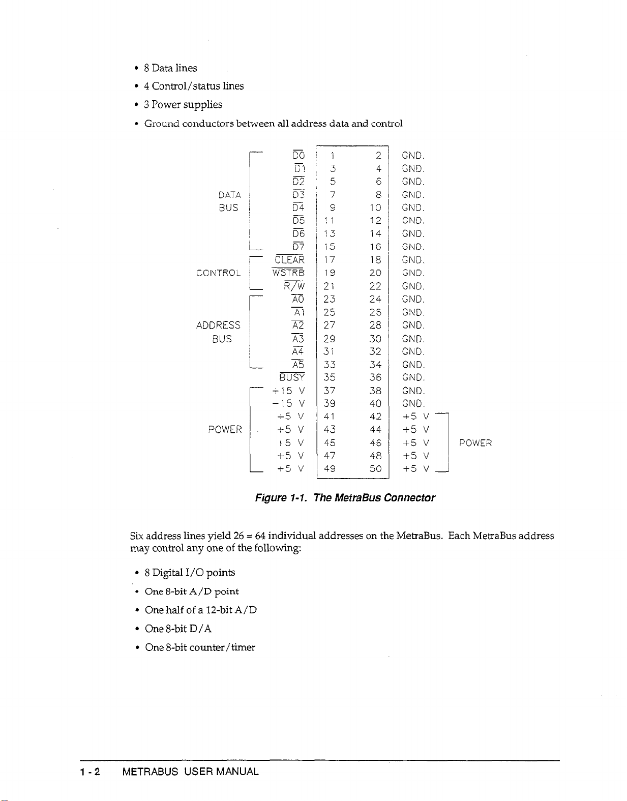
1. The MetraBus cable consists of:
l
6 Address lines
INTRODUCTION I- 1
Page 10
l
8 Datalines
l
4
Control/status lines
l
3 Power supplies
l
Ground conductors between all address data and control
-
-
r
CONTROL j WSTRB
ADDRESS x-2
BUS
!
i
co
c?
-
c2
07
CLEAR
R/W
AO
A:
A3
K-4
A5
BUSY
+15 v
-
15 v
+5 ‘d
POWER
+-5 v
t5 v
+5 v
15 v
-
1
3
5
7
9 10
11
13 14
15 16
17
13 20
21 22
23
25 26
27
29 30
3:
33 34
35 36
37 38
39
41
43
45
47 48
49 50
12
18
24
28
32
40
42
44
46
7
GND.
2
4
GND.
GND.
6
8
GND.
GND.
GND.
GND.
GND.
GND.
GND.
GND.
GND.
GND.
GND.
GND.
GND.
GND.
GND.
GND.
GND.
+5 v
+5 v
+5 v
i5 v
-i5 v
POWE?
I
l-2
Figure 1-l. The MetmBus Connector
Six address lines yield 26 = 64 individual addresses on the MetraBus. Each MetraBus address
may control any one of the following:
* 8
Digital I/O points
* One 8-bit A/D point
* One half of a la-bit A/D
* One 8-bit D/A
l
One 8-bit counter/timer
METRASUS USER MANUAL
Page 11
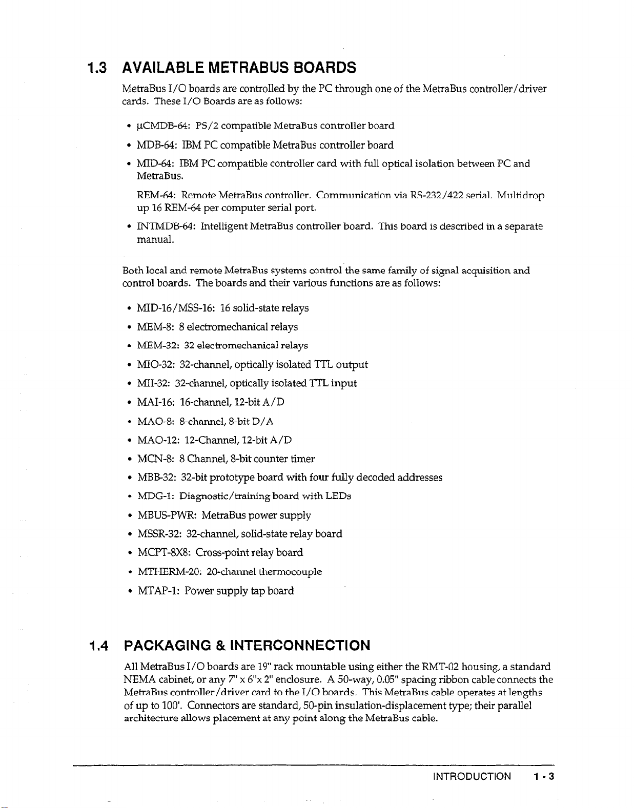
1.3 AVAILABLE METRABUS BOARDS
MetraBus I/O boards are controlled by the PC through one of the MetraBus controller/driver
cards. These I/O Boards are as follows:
l
pCMDB-64: PS/2 compatible MetraBus controller board
l
MDB-64: IBM PC compatible MetraBus controller board
l
MID-64: IBM PC compatible controller card with full optical isolation between PC and
MetraBus.
REM-64: Remote MetraBus controller. Communication via RS-232/422 serial. Multidrop
up 16 REM-64 per computer serial port.
l
INTMDB-64: Intelligent MetraBus controller board. This board is described in a separate
manual.
Both local and remote MetraBus systems control the same family of signal acquisition and
control boards. The boards and their various functions are as follows:
l
MID-16/M%-%: 16 solid-state relays
. MEM-8: 8 electromechanical relays
l
MEM-32: 32 electromechanical relays
l
MIO-32: 32-channel, optically isolated TTL output
l
MII-32: 32-channe1, optically isolated TT’L input
l
MAI-16: Wchannel, 12-bit A/D
l
MAO-8: &channel, 8-bit D/A
l
MAO-12: 12-Channel, 12-bit A/D
l
MCN-8: 8 Channel, &bit counter timer
l
MJ3B32: 32-bit prototype board with four fully decoded addresses
l
MDG-1: Diagnostic/training board with LEDs
l
MBUS-PWR: MetraBus power supply
l
MSSR-32:
l
MCPT-8X8: Cross-point relay board
l
MTHERM-20: 20-channel thermocouple
l
MTAP-1: Power supply tap board
32-channel,
solid-state reIay board
1.4 PACKAGING & INTERCONNECTION
All MetraBus I/O boards are 19” rack mountable using either the RMT-02 housing, a standard
NEMA cabinet, or any 7” x 6”~ 2” enclosure. A 50-way, 0.05” spacing ribbon cable connects the
MetraBus controller/driver card to the I/O boards. This MetraBus cable operates at lengths
of up to 100’. Connectors are standard, 50-pin insulation-displacement type; their parallel
architecture allows placement at any point along the MetraBus cable.
INTRODUCTION 1 -3
Page 12

1.5 CONCEPTUAL VIEW OF METRABUS
MetraBus is an extension of the PC I/O control address space. The MetraBus controller card
implements three control functions, as follows:
* An address Ppinter
l
A data input/output path
l
A reset/clear line
An I/O OUT command from the PC sets the address pointer to a MetraBus I/O board at its
address. Data may then move to or from the selected I/O boards. A RESET/CLEAR may
come from the PC at any time, clearing all I/O boards and resetting the address pointer to
zero.
1.6 PROGRAMMING METRABUS
MetraBus is programmable from any PC-usable language having INPUT and OUTPUT
commands capable of manipulating the I/O bus. Examples of such languages are:
l c
l
BASICA
l
Microsoft PASCAL
l
Assembly
l
GWBASIC
l
TURBO PASCAL
In addition, the REM-64 MetraBus controller allows connection of a MetraBus’system to any
computer with an Rs-232/RS-422 interface. A REM-64 can be controlled from any language
capable of writing and reading the computer’s serial ports.
Programming the MetraBus is a two-step procedure: (1) set the address pointer then (2) read
or write the data. The following discussion wiIl use the variables DATAIO, ADRPTR, and
MRESET in order to help clarify MetraBus progr amming technique. These variables are
generally set at the beginning of your programs for ease of manipulation as follows:
lODATA = 768
20ADRPTR = 769
30MRESET = 770
4OOU-T ADRJ?TR, 01
‘Declare MetraBus data I/O path
'Declare address pointer location
'MetraBus reset location
'Set the address pointer to address #l
5OOUT DATAIO,45 'Write data 45 to address 1
Set the MetraBus address pointer by issuing a single comman d to the MetraBus controller
board. Once set, the address pointer is latched and need not be reset until a different address
is required.
l-4
Writing and reading data from a MetraBus I/O board is transparent once the address pointer
is set. Issuing an OUT command will write data to the targeted I/O board. Likewise, issuing
an INP command will retrieve data from the I/O board via the data I/O path.
OTJT ADRPTR,Ol 'Set address to 1
40
500UT DATAIO,45 'Write data 45 to address 1
6OVAL
= INP(DATAI0) 'Read back data from 1
The MetraBus controller board and all attached MetraBus I/O boards may be reset by writing
to the reset address. Here is an example in BASIC:
METRABUS USER MANUAL
Page 13
40 OUT
MRESET, 00 ‘Clear the MetraBus
Examples of all MetraBus programming features are available on the MetraBus diskettes.
MDB-64 vs. REM-64 Programming
Direct bus plug-in controller boards (MDB-64 and MID-64) program differently than the
REM-64 MetraBus serial controller board. Commands to the MDB-64 and MID-64 are direct
statements to an I/O port. For example, in BASIC:
40 OUT ADRPTR, 01
5OOUT DATAIO, 44
REM-64 co
mmands are writes to a COMl or COM2 serial port. The REM-64 has an on-board
m&!roprccessor which interprets
‘Set address pointer to #l
‘Write data 44 to board #l
co
mmands from the personal computir. The REM-64 issues
commands to the I/O boards (via the MetraBus cable) identical to those issued by an MDB-64
or MID-64. For example, in BASIC:
10 PRINT #l,"B" ; 1 'Activate REM-64 #l
20
PRINT #1, "A" ; 4
30
PRINT #l, "W" ; 44 ‘Write data “44” to I/O board #l
'Set address pointer to MetraBus address 4
Since the MDB-64 and REM-64 use different hardware connections, programs for the MDB-64
are not compatible with those for the REM-64.
Programming l/O Boards
MetraBus I/O boards fall into three major categories:
l
Digital in and out
l
Analog in and out
l
Counter/timer
Digital MetraBus I/O boards program with byte wide (8 bits) write and read commands.
Driving a single digital line high or reading the status of a single line requires one bit.
Therefore, 8 lines (or bits) are controlled when writing to or reading from the digital I/O
boards.
Data to a MetraBus digital ouQut board is latchtid and may be read back from the board. This
data readable feature is usable when manipulating the I/O lines, thus making digita
programming easy.
Analog output boards are controlled as an g-byte port, one byte per channel. The analog
equivalent of the &bit data is output by the DAC on the MetraBus analog output board.
Analog input for the MetraBus is full-featured, allowing user control of application specific
parameters. Prior to reading A/D data from a MetraBus MAI-16, the range channel and type
(12-bit or 8-bit) must be set. An A/D conversion is triggered by software only.
INTRODUCTION
I- 5
Page 14
I
The MCN-8 counter/ timer board has two functions available from software: clear counter
and read counter. Writing to a counter will clear it while reading a counter will retrieve the
current count in the register.
.7
SUMMARY
The remainder of this manual covers the individual MetraBus controller boards and I/O
function boards. The electrical interfacing and programming aspects of each board are
explained.
All explanations and example programs are as if the I/O board is under the control of an
MDB-64. The MIX-64 is a complete and simple implementation of the MetraBus concept.
The MID-64 and REM-64 embody additional features, and are treated in this manual with
programming examples for each.
The lNTMDI3-64 is an intelligent stand-alone driver/controller board for the MetraBus, It is
usable as a dedicated, low-cost controller, or as a satellite controller monitored/controkd by
a larger host computer. This board is described in the INTMDB-64 user’s manual.
Schematics for the MetraBus are available in the MetraBus schematic package.
I-6 METRAHJS USER MANUAL
Page 15
Chapter 2: The Controller Boards
2A.l GENERAL
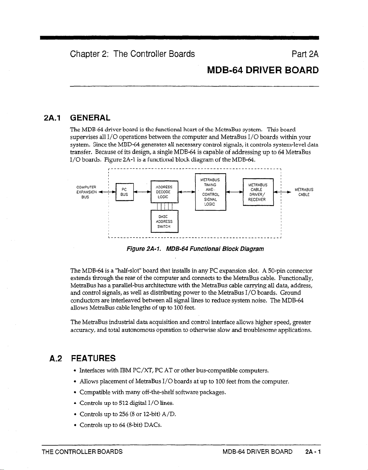
The MDB-64 driver board is the functional heart of the MetraBus system. This board
supervises all I/O operations between the computer and MetraBus I/O boards within your
system. Since the MBD-64 generates all necessary control signals, it controls system-level data
transfer. Because of its design, a single MDB-64 is capable of addressing up to 64 MetraBus
I/O boards. Figure 2A-1 is a functional block diagram of the MDB-64.
I
I I
,
COMPUTER
EXPANSION
BUS
L-------------------------_--_-______---------------,
MDB-64 DRIVER BOARD
MFI’RABUS
ADDRESS
DECODE - AND
LOGIC
BASE
AOORESS
SWITCH
TIMING
CONTROL - DRIVER/ -
SIGNAL
LOGIC
METRABUS
CABLE
RECEIVER I
Part 2A
I
I
I
I
I
I
I
I
I
I
METRABUS
CABLE
The MDB-64 is a ‘half-slot” board that installs in any PC expansion slot. A 50-pin connector
extends through the rear of the computer and connects to the MetraBus cable. Functionally,
MetraBus has a parallel-bus architecture with the MetraBus cable carrying all data, address,
and control signals, as well as distributing power to the MetraBus I/O boards. Ground
conductors are interleaved between all signal lines to reduce system noise. The MDB-64
allows MetraBus cable lengths of up to 100 feet.
The MetraBus industrial data acquisition and control interface allows higher speed, greater
accuracy, and total autonomous operation to otherwise slow and troublesome applications.
A.2 FEATURES
l
Interfaces with IBM PC/XT, PC AT or other bus-compatible computers.
l
Allows placement of MetraBus I/O boards at up to 100 feet from the computer.
l
Compatible with many off-the-shelf software packages.
l
Controls up to 512 digital I/O lines.
l
Controls up to 256 (8 or U.-bit) A/D.
Figure 2A-1. MDB-64 Functional Block Diagram
l
Controls up to 64 @-bit) DACs.
THE CONTROLLER BOARDS
MDB-64 DRIVER BOARD 2A-1
Page 16

l
Extremely cost effective.
l
Adapts to your changing requirements.
2A.3 SPECIFICATIONS
Number of addressable MetraBus 64
ports:
Maximum MetraBus data transfer 80 kbytes/s
rate:
Maximum drivable cable length: 100 feet at full speed
200 feet at reduced speed
MetraBus cable type:
MetraBus connector:
Power required:
50 conductor ribbon cable
3M 3425-4050
-+ 5
V: 250 rr~4
typical, 325 n-4 maximum
2A.4 SE’TJING THE BASE ADDRESS SWITCH
The MD13-64 uses four consecutive locations in the PC I/O address space. This address space
extends from decimal 512 to 1023.
for 768 (3OOh), as shown in Figure 2A-2.
-2
The MDB-64 base address switch is preset by the factory
ADDRESS
ADDRESS UNE VALUES:
LINE DECIWL HEX
512
200
256 100
Figure ZA-2. Defautt Base Address Switch SettiRgs.
If I/O address 768 (300h) is occupied by another device, you must reset the base address
switch. Refer to your PC manual for available addresses in the I/O space.
Once you have selected an address, change the base address switch accordingly. For
assistance with the settings, use the INSTALLEXE program provided on your MetraBus
diskette.
NOTE: Setting the base address to a location used by another device
may cause erratic operation or PC system failure.
To run the INSTALLEXE program, change to the appropriate directory and at the DOS
prompt, and type
INSTALL
2A-2 METRABUS USER MANUAL
Switch settings indicate o voluc o!
512 i 256 = 768 Dccimoi
(768 decimal, 300h)
followed by [Enter]. When the program asks for the desired
Page 17
base address, enter the new base address in decimal and press [Enter]. The program rounds
your address to the nearest 4-bit boundary and checks for conflicts with other devices.
Choosing an address less than 512 or greater than 1023 results in an error message. When the
program determines an address is suitable, it displays the settings you must make on the Base
Address Switch.
INSTALL.EXE performs an additional function: it generates a file named MBUS.ADR
containing the newly selected Base Address Switch settings. The address in the file
MBUS.ADR may then be read by application programs as an alternative to m-defining the
MDB-64 address in every program. The following short BASIC program shows how to obtain
the address from the MBUSADR file.
lOOPEN "KBUS.ADR" FOR INPUT AS #l
20
INPUT #~,BASADR
30 PRINT BASADR
40
CLOSE #l
The base address location is returned to the variable BASADR for use by your application
program.
2A.5 INSTALLING THE MDB-64 FUSE.(Fl)
MBD-64 fuse Fl allows the PC to supply +5 VDC to the MetraBus I/O boards via the
MetraBus cable. Large systems and those using +15 V will require an additional high-quality
power supply such as the MBUS-PWR (see Contents).
Failure to remove the fuse when using the MDB-44 with an external power supply causes the
fuse to blow.
If the MetraBus System is to draw power from the PC power supply, the fuse Fl must be
installed. This fuse is a Littlefuse #312001,3AG 2A fast blow.
In this case, Fuse Fl must be removed.
2A.6 INSTALLING THE MDB-64 DRIVER CARD
1. Unplug your computer.
Remove the cover of your computer and select any empty expansion slot. Remove the
2.
backplate from the selected slot. If you are using an IBM PC/XT, note that the MDB-64
does
not
operate correctly in the short expansion slot farthest to the right (I8) next to the
power supply. This slot is reserved for the IBM expander card and is not available for
peripherals since the bus signals are slightly different from the other slots.
Make certain that the base address switch is properly set and fuse Fl is installed/removed
3.
(as needed).
Lnsert the MDB-64 into a PC expansion slot. If needed, straighten the locking tabs on the
4.
ends of the connector prior to insertion.
Once the board is in place, plug the MeiraBus cable into the MDB-64. Make sure the
5.
locking tabs are locked around the mating portions of the MetraBus connector. The
mating portions of the connectors are keyed and should plug-in easily. Check the
keyways for correct alignment prior to insertion, Avoid applying force to the connector.
Secure the MDB-64 backplate to the computer frame with a screw and replace the
6.
computer cover.
THE CONTROLLER BOARDS
MDB-64 DRIVER BOARD 2A-3
Page 18
NOTE: The MDB-64 is shipped with two resistor networks. These
termination resistors are to be installed in sockets RN1 and RN2 on the
last MetraBus I/O board in your system. These resistor networks are
used to minimize signal reflection due to long MetraBus cable lengths.
They are optional, however, and have little effect for cables of 50 feet or
less.
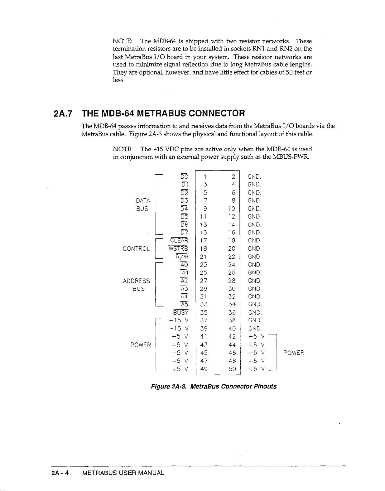
2A.7 THE MDB-64 METRABUS CONNECTOR
The MDB-64 passes information to and receives data from the MetraBus I/O boards via the
MetraBus cable. Figure ZA-3 shows the physical and functional layout of this cable.
NOTE: The +15 VDC pins are active only when the MDB-64 is used
in conjunction with an external power supply such as the MBUS-PWR.
DATA
BUS
POWER
BUSY
+15 v
-15 v
+5 v
+5 v
+5 v
+5 v
L t5v
1
3
5 6
7
9 10
1 1
13
15 16
17
19 20
21 22
23 24
25 26
27 28
29
31
33
35 36
37
39 40
41
43
45 46
47 48
49 50
12
14
18
30
32
34
38
42
44
GND.
2
4
GND.
GND.
GND.
8
GND.
GND.
GND.
GND.
GND.
GND.
GND.
GND.
GND.
GND.
GND.
GND.
GND.
GND.
GND.
GND.
+5 v
i-5 v
+5 v
-1-5 v
i-5 v
POWER
2A-4
Figure ZA-3. MetraBus Connector Pinouts
METRABUS USER MANUAL
Page 19
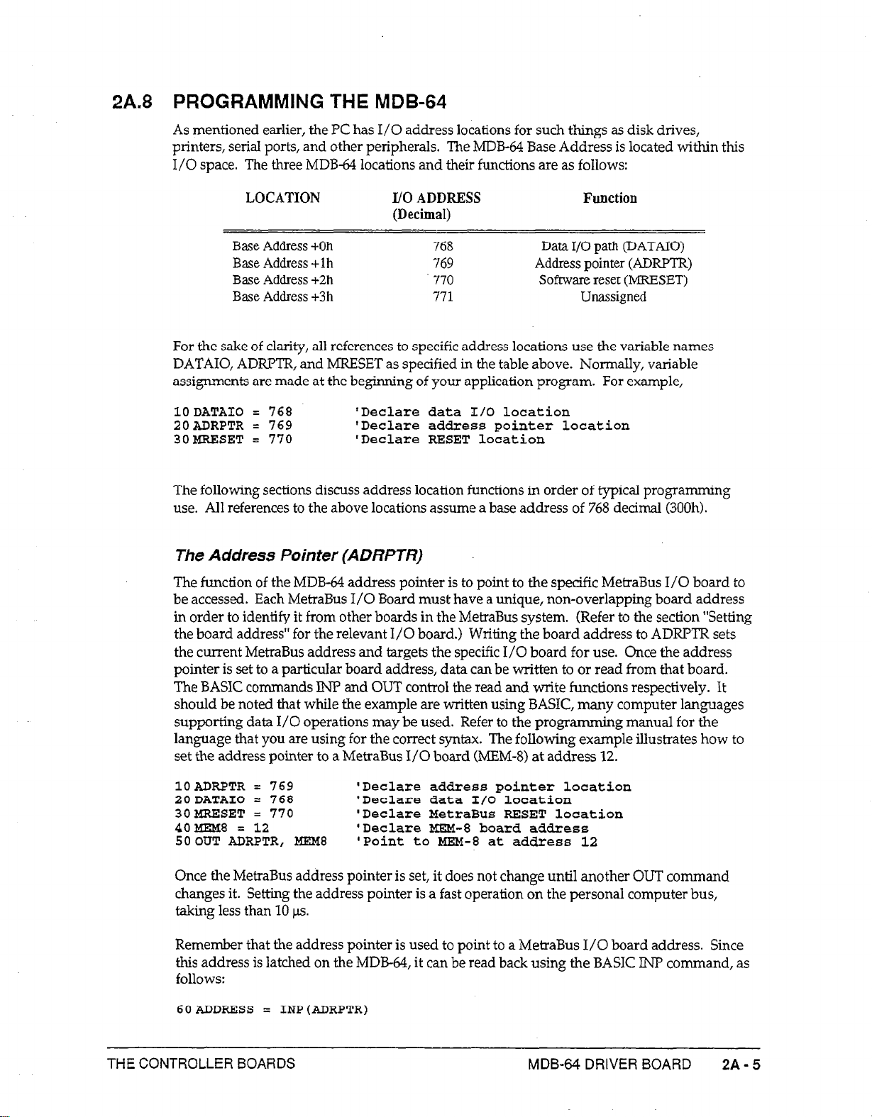
2A.8 PROGRAMMING THE MDB-64
As mentioned earlier, the PC has I/O address locations for such things as disk drives,
printers, serial ports, and other peripherals. The MDB-64 Base Address is located within this
I/O space. The three MDB-64 locations and their functions are as follows:
LOCATION I/O ADDRESS
(Decimal)
Base Address +-Oh
Base Address +lh
Base Address +2h
Base Address +3 h
768 Data I/O path (DATAIO)
769
‘770 Software reset (PRESET)
771 Unassigne4l
Address pointer (ADRPTR)
Function
For the sake of clarity, all references to specific address locations use the variable names
DATAIO, ADRFTR, and MRESET as specified in the table above. Normally, variable
assignments are made at the beginning of your application program. For example,
ZODATAEO = 768 'Declare data I/O location
20ADRPTR = 769 'Declare addxess pointer location
30WSET = 770 'Declare RESET location
The following sections discuss address location
use. All references to the above locations assume a base address of 768 decimal
The Address Pointer
(ADRPTR)
functions
in order of typical programming
(300h).
The function of the MDB-64 address pointer is to point to the specific MetraBus I/O board to
be accessed. Each MetraBus I/O Board must
in order to identify it from other boards in the MeiraBus system.
have
a unique, non-overlapping board address
(Refer to the section “Setting
the board address” for the relevant I/O board.) Writing the board address to ADFUYIR sets
the current MetraBus address and targets the specific I/O board for use. Once the address
pointer is set to a particular board address, data can be written to or read from that board.
The BASIC commands IN? and OUT control the read and write functions respectively. It
should be noted that while the example are
written
using BASIC, many computer languages
supporting data I/O operations may be used. Refer to the programming manual for the
language that you are using for the correct syntax. The following example illustrates how to
set the address pointer to a MetraBus I/O board (MEM-8) at address 12.
10ADRPTR = 769
2QDATAIO = 76%
30MRELSET = 770
4OMBf8 = 12
5OOUT ADRPTR, MEM8 'Point to HEM-8 at address 12
Once the MetraBus address pointer is set, it does not change until another OUT command
changes it. Setting the address pointer is a fast operation on the personal computer bus,
taking less than 10 p.
Remember
that
the address pointer is used to point to a MetraBus I/O board address. Since
this address is latched on the MDB-64, it can be read back using the BASIC INP command, as
follows:
60ADDREXS = INP(ADRPTR)
THE CONTROLLER BOARDS
'Declare address pointer location
'Declare data I/O location
'Declare HetraBus RESET location
‘Declare m-8 board address
MDB-64 DRIVER BOARD
ZA-5
Page 20
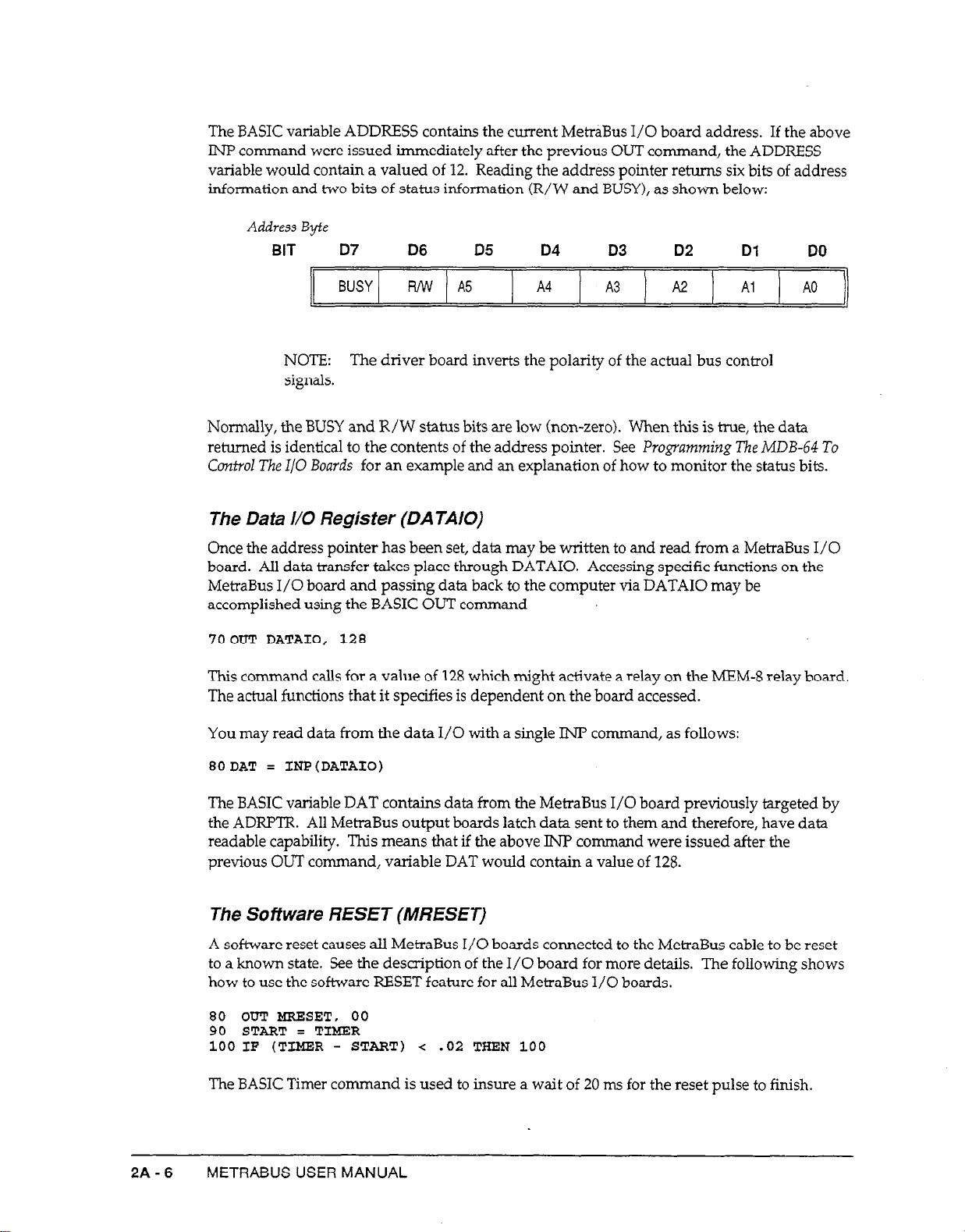
The BASIC variable ADDRESS contains the current MetraBus I/O board address. If the above
INP command were issued immediately after the previous OUT command, the ADDRESS
variable would contain a valued of 12. Reading the address pointer returns six bits of address
information and two bits of status information (R/W and BUSY), as shown below:
Address Byte
BIT D7
D6
D5
D4 D3 D2
Dl
DO
BUSY R/w A.5
A4
A3
A2
Al A0
NOTE: The driver board inverts the polarity of the actual bus control
signals.
Normally, the BUSY and R/W status bits are low (non-zero). When this is true, the data
returned is identical to the contents of the address pointer. See Programming The MDB-64 7’0
Covttiol The I/O Boar& for an example and an explanation of how to monitor the status bits.
The Data l/O Register (DATAIO)
Once the address pointer has been set, data may be written to and read from a MetraBus I/O
board. All data transfer takes place through DATAIO. Accessing specific functions on the
MetraBus I/O board and passing data back to the computer via DATA10 may be
accomplished using the BASIC OUT command
70 OUT DATAIO, 128
This command calls for a value of 128 which might activate a relay on the MEM-8 relay board.
The actual functions that it specifies is dependent on the board accessed.
You may read data from the data I/O with a single IN7 command, as follows:
EODAT = INP(DATAI0)
The BASIC variable DAT
contains
the ADRPTR. All MetraBus output boards latch data sent to them and therefore, have data
readable capability. This means that if the above IN? command were issued after the
previous OUT command, variable DAT would contain a value of 128.
The Sofiware RESET (MRESET)
A software reset causes alI MetraBus I/O boards connected to the MetraBus cable to be reset
to a known state. See the description of the I/O board for more details. The following shows
how to use the software RESET feature for all MetraBus I/O boards.
80 OUT HRZSET, 00
90 START = TIMER
100 IF (TIZGR - START) < .02 THEN 100
The BASIC Timer command is used to insure a wait of 20 ms for the reset pulse to finish.
214-6 METRABUS USER MANUAL
data from the MetraBus I/O board previously targeted by
Page 21
Notes On The Use Of Compiled Or Assembled Languages
Execution speeds with compiled and assembled languages may call for precautions. As
mentioned earlier, when reading the currently latched MetraBus I/O address, the lowest six
bits contain address information while the two most significant bits carry status information.
Prior to any BASIC Inp or Out command, check the status bits (R/W and Busy). The
following example shows the proper status checks.
DATA10 = 768
10
ADRPTR = 769
20
MRESET = 770
30
MA116 = 8
40
OUT MRESET, 00
50
60 START = TIMR
IF (TIKER - START) <
70
IF (INPUDRPTR) AND 192)
80
90 OUT ADRPTR, HAI16+2
IF (INP(ADFU?TR) AND 192)
100
OUT DATAIO, 18
110
IF (INP(ADRPTR) AND 192)
120
130 OUT ADRPTR, HAI16+1
140 IF (INP(ADRPTR) AND 192) THEN 140
150 AIN = INP(DATAI0)
.02 THEN 70
THEN 80
THEN 100
THEN 120
'Declare I/O location
'Declare address pointer location
'Declafe MetraBus RESET location
'Declare MAI- board address
'Input Time
'Wait 20 ms
'Check status
'Point to
'Check status
'Set gain to +5 V range on than 2
'Check status
'Point to result of conversion
'Check status
'Return result to computer
g-bit
A/D resolution
Programming The MDB-64 To Control The l/O Boards
As described above, the three MDB-64 I/O locations have quite distinct
of execution generally follows a consistent pattern when programming any MetraBus I/O
board. The following examples illustrate programming techniques used with both digital and
analog
I/O Boards. For prograrnmin
g information on a specific board, refer to the board
description.
Digital l/O Boards
functions.
Their order
Digital I/O boards are the easiest to control. Data can be written to DATAIO
setting the address pointer. Digital output boards typically have several &bit ports. In the
following example, a digital output board (MIO-32) is at board address 0 and the MDB-64 is at
computer I/O Address 768 decimal (3OOh).
lODATA = 768
20ADRPTR = 769
3OMRESET = 770
40MI032 = 0 'Declare MIO-32 board address
5OOUT
ADRPTR, MI032
6OOUT DATAIO, 255
Lines 10 through 40 declare the locations of the MetraBus DATAIO, ADRF’TR, and
MRESET functions, as well as declare the MIO-32 board address. Line 50 sets the address
pointer to the MIO-32 digital output board. Line 60 outputs a value of 255 to the MIO-32,
setting all outputs high.
THE CONTROLLER BOARDS
'Declare data
'Declare
address pointer location
I/O
location
'Declare MetraBus REXXT location
'Point to MIO-32
at
address 0
'Output bit pattern 1111 1111
MDB-64 DRIVER BOARD
soon
after
the
2A-7
Page 22
Digital input board (Mu-32) programmin
g is similar to that for digital output boards. Digital
input boards typically have several B-bit ports. After the address pointer has been set, data
can be read from the DATAIO, as follows:
lODATA = 768 'Declare Data I/O Location
20ADRPTR = 769 'Declare Address Pointer Location
30MRBSET = 770 'Declare MetraBus RESET Location
40MII32 = 4 'Declare MII-32 Board Address
5OOUT ADRPTR, MI132 'Point to MII-32 at Address 4
60DATIN = INP(DATAI0) 'Get data from DATA10
Lines 10 through 40 declare the locations of the MetraBus DATAIO, ADKPTR, and
the
MRESET functions, as well as declare the MU-32 board address. Line 50 sets the address
pointer to the MIl-32 digital input board. Line 60 reads the contents of one of the four &bit
ports on the m-32 and stores the result in the BASIC variable DATIN.
Analog I/O Boards
Analog output boards (MAO-8) use one MetraBus I/O address per channel. Setting the
Address Pointer to the appropriate address and writing data to the DATAIO will produce an
analog output. The following example shows how to set the address pointer and output a
voltage.
lODATA = 768
20ADRPTR = 769
30MRESET = 770
4OMAO8 = 8
5OOUT ADRPTR, MAO8
6OOUT DATAIO, 255
7OOUT DATAIO, 0
8OOUT ADRPTR, MA116
Lines 10 through 40 declare the locations of the MetiaBus DATAIO, ADRPTR, and the
MRXSET functions, as well as declare the MAO-8 board address. Line 50 sets the address
pointer to channel 0 of the MAO-8 board. Line 60 outputs the highest voltage possible for its
selected range.
'Declare Data I/O Location
'Declare Address Pointer Location
'Declare MetraBus RESET Location
'Declare MAO-8 Board Address
'Point to HAO-8 at Address 8
'Output Pull Range Voltage
'Start A/D Conversion
'Select the MSB's address
Analog Input boards (MAI-16) require additional steps, however, in order to set the gain and
resolution for the desired channel prior to taking data. Assume an MAI- board has been set
at Board Address 8.
lODATA = 768 'Declare Data I/O Location
20ADRPTR = 769 'Declare Address Pointer Location
30MRESET = 770
35MAI16 = 8
4OOUT ADRPTR, KAI16+2'Point to 8-bit A/D resolution
SOOUT DATIO,18 'Set gain to + 5 V
6OCUT ADRPTR, MAI16+1'Point to result of conversion
90AIN = INP(DATAI0) 'Return result to computer
Lines 10 through 35 declare the locations of the MetraBus DATAIO, ADRPTR, and the
MXESET functions, as well as declare the MN-16 board address.
Line 40 selects the gain/channel selection mode for the board at address 8 (see MN-16
description for full explanation).
2A-a METRABUS USER MANUAL
'Declare MetraBus RESET Location
'Declare MAI- Board Address
range
on channel 2
Page 23

Line 50 sets the gain to + 5V full scale range on channel 2.
Line 60 points to the B-bit conversion mode for the board and channel previously selected.
Line 70 starts the A/D conversion process.
Line 80 points to the results of the A/D conversion.
Line 90 returns the result to the computer and stores the data in the variable AJN.
THE CONTROLLER BOARDS
MDB-64 DRIVER BOARD 2A-9
Page 24

cl
P
2A-10 METRABUS USER MANUAL
Page 25

Chapter 2: The Controller Boards
2B.l GENERAL
Part 2B
MID-64 DRIVER BOARD
The MID-64 driver board optically isolates the computer bus from
acquisition and control
computer and MetraBus I/O boards within your
system.
The MID-64 supervises all I/O operations between the
system.
All necessary control signals are
the
MetraBus data
generated within the MID-64, so you don’t have to worry about system level data transfer.
Because of its design, a single MID-64 is capable of addressing up to 64 MetraBus I/O boards.
The MID-64 contains an on-board, programmable counter/timer capable of periodic
system
interrupt generation. This allows the MetraBus operation in a foreground/background mode
emulating many common multitasking environments. A functional block diagram of the
MlD-64 is provided in Figure 2B-1.
r--------------------------------------------------------------------~
METfZABUS
COMPUTER :
EXPANSION -
BUS
PC
I BUS -
ADDRESS
OECOOE -
LOGIC
BASE
ADDRESS
WITCH
TIMING MEmABuS !
AND
CONTROL - ISOLAlORS DRIER/ ?-+ CABLE
SIGNAL RECEIVER 1
LOGIC
CABLE ’ Mmus
Figure 2B-1. MID-64 Functional Block Diagram
When installed, a 50-pin connector extends out the rear of the computer and connects to the
MetraBus cable. Functionally, the MetraBus has a parallel bus architecture with the MetraBus
cable carrying all data, address, and control signals, as well as distributing power to the
MetraBus I/O boards. Ground conductors are interleaved between all signal lines to increase
system noise immunity. The MID-64 has been designed to allow MetraBus cable lengths of up
to loo feet.
The MetraBus industrial data acquisition and control interface, in conjunction with your
present computer, allows higher speed, greater accuracy, and total autonomous operation to
previously slow, troublesome, applications.
THE CONTROLLER BOARDS
MID-64 DRIVER BOARD
2B-1
Page 26
2B.2 FEATURES
l
Connects with IBM PC/XT, PC AT, or other bus compatible computers.
l
Allows placement of MetraBus I/O at up to 100 feet from the PC.
l
Full optical isolation to 500 Volts.
l
Fully compatible with software written for the MDB-64 driver board.
l
Interrupt generation capability.
l
Controls up to 512 digital I/O lines.
l
Controls up to 256 (8 or 12-bit) A/D.
l
Controls of 64 @-bit) DACs.
l
Controls up to 64 counter/timers.
l
Extremely cost effective.
l
Adapts to your changing requirements.
28.3 SPECIFICATIONS
Number of Addressable MetraBus
64
Ports:
2B.4
Maximum MetraBus Data TrmR;yz
80 kbytes/s
Maximum Drivable Cable Length: 100 feet at full speed
200 feet at reduced speed
+ 5
Power Required:
PC to MetraBus Isolation:
V: 250 mA typical, 325 rnA maximum
500 volts (minimum)
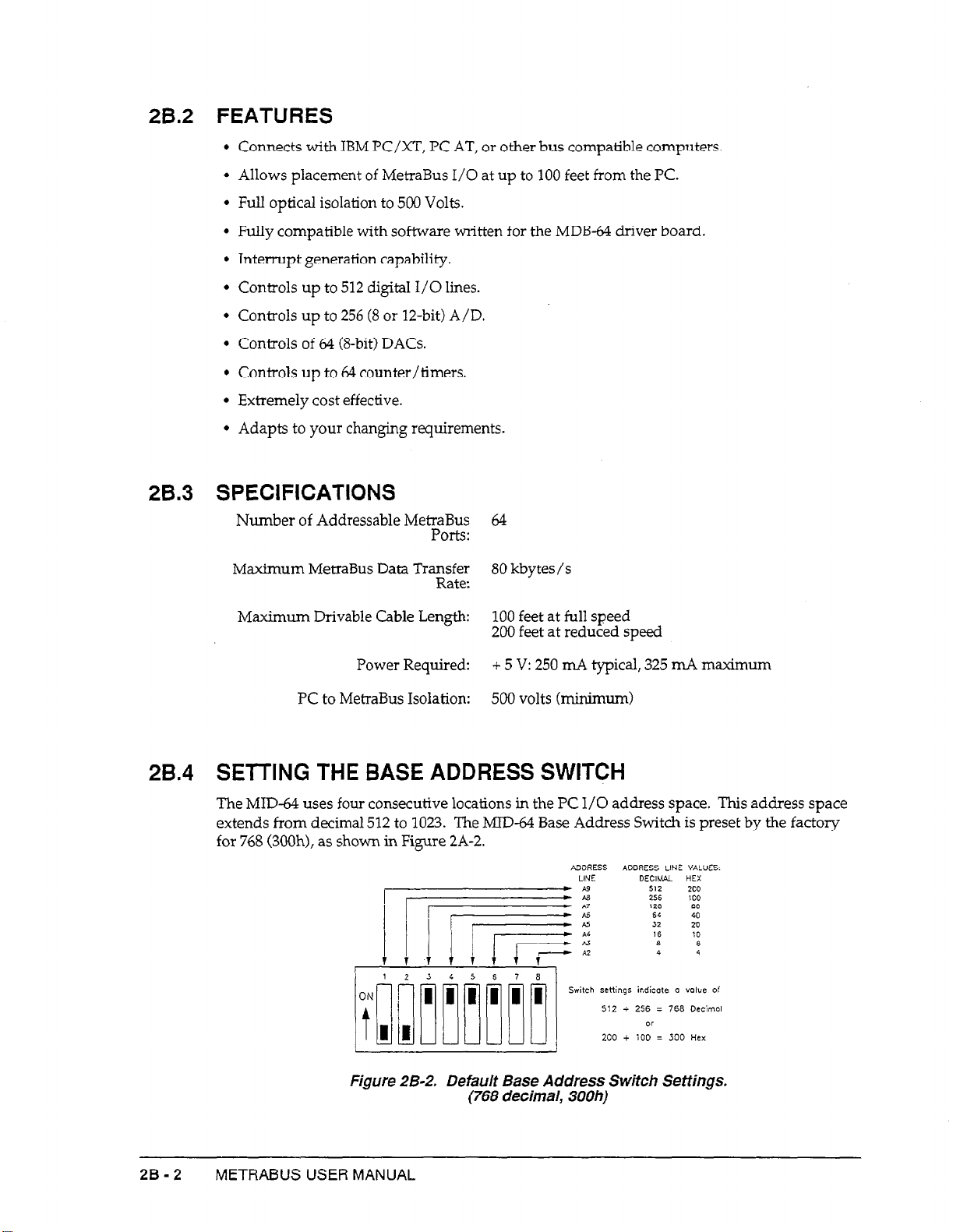
SETTING THE BASE ADDRESS SWITCH
The MID-64 uses four consecutive locations in the PC I/O address space. This address space
extends from decimal 512 to 1023. The MID-64 Base Address Switch is preset by the factory
for 768 (3OOh), as shown in Figure 2A-2.
ADDRESS
LINE
qs iedicote 0 value o!
i 256 = 766 Decimal
or
+ iOD = 300 Hex
Figure 2B-2. Default Base Address Switch Settings.
2B-2 METRABUS USER MANUAL
(768 decimal, 300h)
Page 27
If I/O address 768 (300h) is occupied by another device, you must reset the base address
switch. Refer to your PC manual for available addresses in the I/O space.
Once you have selected an address, change the base address switch accordingly. For
assistance with the settings, use the INSTALLEXE program provided on your MetraBus
diskette.
NOTE:
may cause erratic operation or PC system failure.
To run the INSTALL.EXE program, change to the appropriate directory and at the DOS
prompt, and type INSTALL followed by [Enter]. When the program asks for the desired
base address, enter the new base address in decimal and press [Enter]. The program will
round your address to the nearest 4-bit boundary and check for conflicts with other devices.
Choosing an address less than 512 or greater than 1023 results in an error message. When the
program determines an address is suitable, it displays the settings you must make on the base
address switch.
INSTALL.EXE also generates a file named MBUSADR containing the newly selected base
address switch settings. The address in the file &!fHJS.ADR may then be read by application
programs as an alternative to redefining the MID-64 address in every program. The
following short BASIC program shows how to obtain the address from the MBUS.ADR file.
1OOPKN "MBUS.ADR" FOR INPUT AS #1
20 INPUT #l,BASADR
30PRINT BASADR
40
CLOSE #l
The base address location is returned to the variable BASADR for use by your application
program.
Setting the base Aadress to a location used by another device
2B.5 USE OF THE AUXILIARY POWER SUPPLY
An auxiliary power supply such as the MBUS-Pm is required for operation of the MID-64,
since it does not distribute power from the computer’s supply. See the chapters of this
manual dealing with the MBUS-PWR for specifications and installation instructions.
2B.6 INSTALLING THE MID-64 DRIVER CARD
1. Unplug your computer.
2. Remove the cover of your computer and select any empty expansion slot. Remove the
back-plate from the selected slot.
3. Make certain that the base address switch is properly set.
4. Insert the MID-64 into the expansion slot. It may help to straighten the locking tabs on the
ends of the connector prior to insertion.
THE CONTROLLER BOARDS MID-64 DRIVER BOARD 28-3
Page 28
5. Once the board has been inserted, plug the MetraBus cable into the MID-64. Make sure
that the locking tabs are locked around the mating portions of the MetraBus connector.
The mating portions of the connectors are keyed and should plug-in easily.
Check the
keyways for correct alignment prior to insertion. Avoid applying force to the connector.
6. Secure the MID-64 back-plate to the computer frame with a screw and replace the
computer cover.
NOTE:
The MID-64 is shipped with two resistor nehvorks.
termination resistors are to be installed in sockets RN1 and RN2 on the
last MetraBus I/O board in your system. These resistor networks are
used to minimize signal reflection due to long MetraBus cable lengths.
They are optional, however, and have little effect for cables of 50 feet or
less.
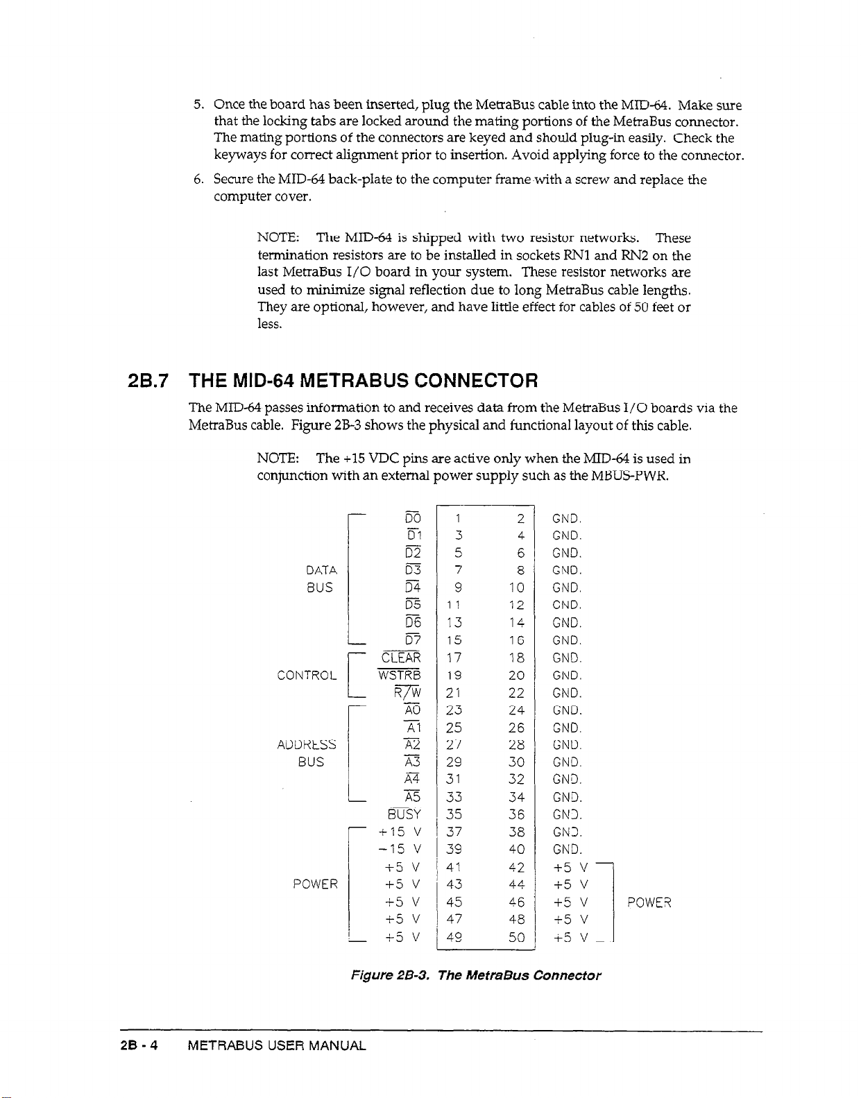
2B.7 THE MID-64 METRABUS CONNECTOR
The MID-64 passes information to and receives data from the MetraBus I/O boards via the
MetraBus cable. Figure 2B-3 shows the physical and functional layout of this cable.
The
+15
NOTE:
conjunction with an external power supply such as the MBUS-PWR.
DATA m
BUS
CONTROL
ADDRESS /
BUS
POWER +5 v
VDC pins are active only when the MID-64 is used in
r
L
C
r
i
r
i
m
D-1
m
m
iz
tie
m
CLEAR
WSTRB
%
-iii
A2
23
XT
A5
BUSY
+I5 v
-15 v
i5 v
+.5 v
+5 v
+5 v
1
3
5
7
9 IO
1 1
13 14
15
17
19
2 1 22
23
25 26
27 28
29 30
31
33 34
35
37
39 40
4’1
43 44
45
47
49
12
16
18
20
24
32
36
38
42
46
48
50
2
4
6
8
GND.
GND.
GND.
GND.
GND.
GND.
GND.
GND.
GND.
GND.
GND.
GND.
GND.
GND.
GND.
GND.
GND.
GN3.
GN3.
GND.
+5 v
+5 v
+5 v
+5 v
+5 v
These
POWER
I
28-4
Figure 28-3. The MetraBus Connector
METRABUS USER MANUAL
Page 29
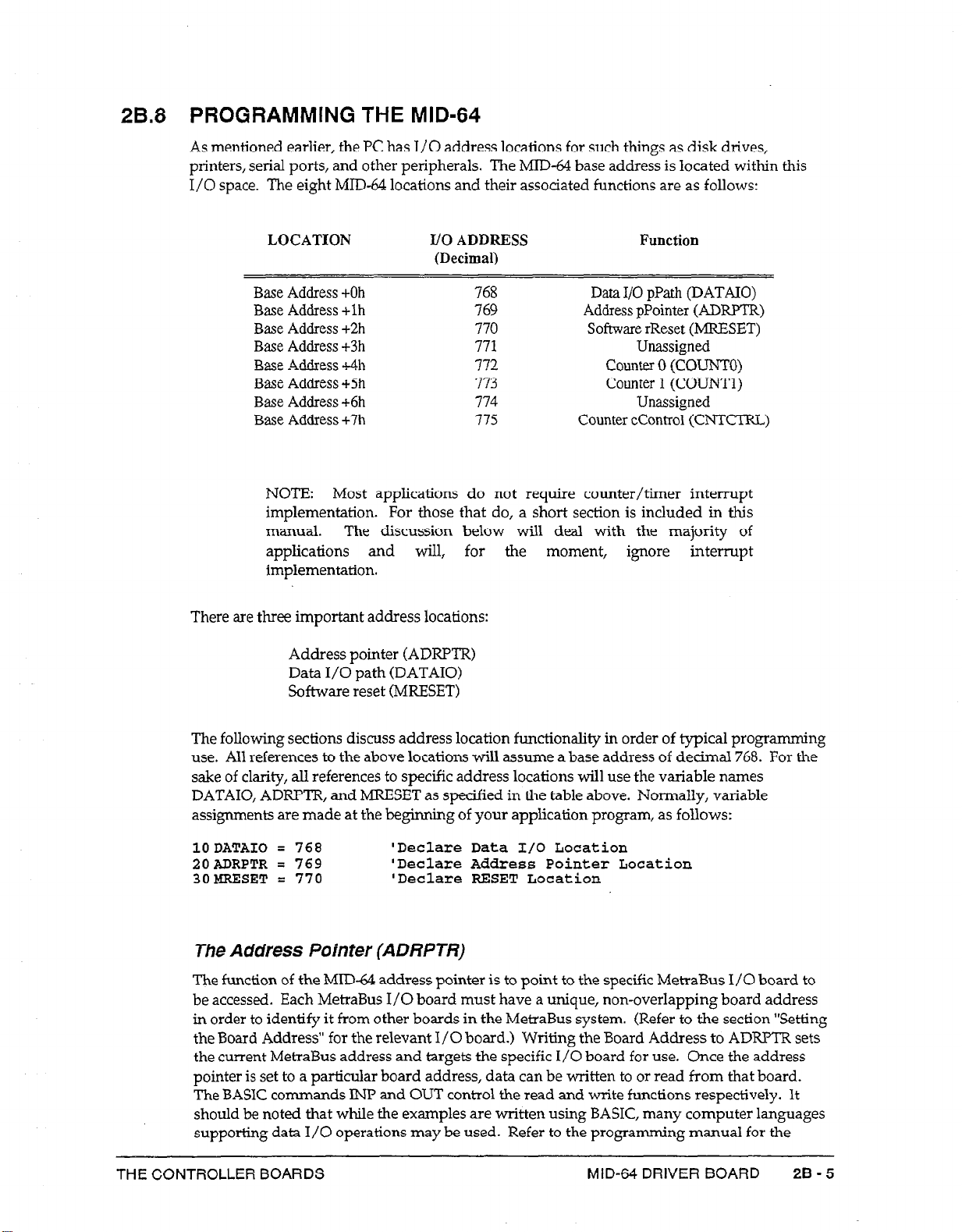
2B.8 PROGRAMMING THE MID-64
As mentioned earlier, the PC has I/O address locations for such things as disk drives,
printers, serial ports, and other peripherals. The MID-64 base address is located within this
I/O space. The eight MID-64 locations and their associated functions are as follows:
LOCATION
I/O ADDRESS
(DecimaI)
Base Address +Oh
Base Address +lh
Base Address
+2h
Base Address +3h
Base -4~Uress 4h
Base Address +5h
Base Address +6h
Base Address +7h
768
769
770
771
772
773
774
775
NOTE: Most applications do not require counter/timer interrupt
implementation.
For those that do, a short section is included in this
manual. The discussion below will deal with the majority of
applications and wiIl, for the moment, ignore interrupt
implementation.
There are three important address locations:
Address pointer (ADRF’TR)
Data I/O path (DATAIO)
Software reset (MRESET)
Function
Data I/O pPath (DATAIO)
Address pPointer (ADRXR)
Software rReset (MRESET)
Unassigned
counter 0 (COUNTO)
Counter 1 (COTJNTI)
Unassigned
Counter cContro1 (CNTCTRL)
The following sections discuss address location functionality in order of typical programming
use. All references to the above locations will assume a base address of decimal 768. For the
sake of clarity, all references to specific address locations will use the variable names
DATAIO, ADRPTR, and MRESET as specified in the table above. Normally, variable
assignments are made at the beginning of your application program, as follows:
1ODATAIO = 768 'Declare Data I/O Location
20ADRPTR = 769 ‘Declare Address Pointer Location
30MRESET = 770
The Address Pointer (ADRPTR)
The function of the MID-64 address pointer is to point to the specific MetraBus I/O board to
be accessed. Each MetraBus I/O board must have a unique, non-overlapping board address
in order to identify it from other boards in the MetraBus system. (Refer to the section “Setting
the Board Address” for the relevant I/O board.) Writing the Board Address to ADRPTR sets
the current MetraBus address and targets the specific I/O board for use. Once the address
pointer is set to a particular board address, data can be written to or read from that board.
The BASIC commands INP and OUT control the read and write functions respectively. It
should be noted that while the examples are written using BASIC, many computer languages
supporting data I/O operations may be used. Refer to the programming manual for the
THE CONTROLLER BOARDS
‘Declare RELSET Location
MID-64 DRIVER BOARD
28-5
Page 30

language that you are using for the correct syntax. The following example illustrates how to
set ADRF’TR to address 12 for a MEM-8 board:
10 ADRPTR = 769
20DATAI0 = 768
30MRESET = 770
40MEMB = 22 ‘Declare MEN-8 board address
50
OUT ADRPTR, KEN8
'Declare address pointer location
'Declare data I/O location
'Declare MetraBus RESET location
'Point to MELM-8 at address 12
Once the MetraBus address pointer is set, it does not change until another OUT command
changes it.
Setting the Address pointer is a fast operation on the personal computer bus,
taking less than 10 microseconds. Since this address is latched on the MID-&, it can be read
back using the BASIC INF’ command, for example:
60
ADDRESS = INPCADRPTR)
The BASIC variable ADDRESS contains the address of the MetraBus I/O board currently
targeted. If the above INP co
mmand is issued soon after the previous OUT command, the
ADDRESS variable would contain a value of 12. Reading the address pointer returns 6 bits of
address information and two bits of status information (R/W and BUSY), as follows:
Address Byte
BIT D7 D6 D5 D4
BUSY Pu’W A5
A4
D3 D2 Dl
A3
A2 Al A0
DO
NOTE: The driver board inverts the polarity of the actual
signals.
bus control
Normally, the BUSY and R/W status bits will be low (non-zero>. When this is true, the data
returned is identical to the contents of the address bus. See Programming The MID-64 To
Control The I/O Boards for an example and an expknation of how to monitor the status bits.
The Data I/O Register (DATA/O)
Once the address pointer has been set, data may be written to and read from a targeted
MetraBus I/O board. All data transfer takes place through DATAIO. Accessing specific
functions on the MetraBus I/O board and passing data back to the computer via DATA10
may be accomplished using the BASIC OUT command:
7OOUT DATAIO, 128
This command outputs a value of 128 which might activate a relay on the
The actual functions that it specifies is dependent on the board accessed.
Data
can be read from the
80DAT
= INP (DATAIO)
Data I/O with a single lNP con-man
d, as follows:
The BASIC variable DAT wiIl contain data from the MetraBus I/O board previously targeted
by the ADRM’R. All MetraBus output boards latch data sent to them and therefore, have data
MEM-8
relay
board.
2B-6 METRABUS USER MANUAL
Page 31

readback capability. This means that if the above INP command were issued after the
previous OUT command, variable DAT would contain a value of 128.
The Software RESET (MRESET)
A software reset causes all MetraBus I/O boards connected to the MetraBus cable to be reset
to a known state. See the description of the I/O board for more details. The following shows
how to use the software RESET feature for al1 MetraBus I/O boards.
OUT MRESET, 00
80
90 START = TIMER
IF (TIMF,R - START) < .3 THEN 100
100
The BASIC Timer command is used to insure a wait of 300 ms for the reset pulse to finish.
Notes On The Use Of Compiled Or Assembled Languages
The execution speed of compiled and assembledIanguages calls for precautions. As
mentioned earlier, when reading the currently latched MetraBus I/O address, the lowest six
bits contain address information while the two Most Significant Bits carry status information.
Prior to any BASIC Inp or Out command, you should check the status bits (R/W and Busy).
The following example shows the proper status checks.
DATA10 = 768
10
ADRPTR = 769
20
MRESET = 770
30
MA116 = 8
40
OUT MRESET, 00
50
60 START = TIMER
IF (TIMER - START)
70
80 IF (INJ?(ADRPl'R) AND
90 OUT ADRPTR, MAI16+2
100 IF (INP(ADRPTR) AND
OUT
110
120 IF (INP(ADRmR) AND
130 OUT ADRPTR, MA116+1
140 IF (INP(ADRPTR) AND
150 AIN = INP(DATAI0)
DATAIO, 18
<
.3 THEN 70
192) TEEN 80 'Check status
192) TW3N 100
192) TWEN 120
192) THEN 140
'Declare I/O location
'Declare address pointer location
'Declare MetraBus RESET location
'Declare MAI- board address
'Input Time
'Wait 300 ms
'Point to B-bit A/D resolution
'Check status
'Set gain to +5 V range on than 2
'Check status
'Point to result of conversion
'Check status
.'Return result to computer
Programming The MID-64 To Control The I/O Boards
As described above, the eight MID-64 I/O locations have distinct functions. Their order of
execution generally follows a consistent pattern when programming any MetraBus I/O board.
The following examples illustrate programmin
Analog I/O Boards. Detailed programmin g information on a specific board, refer to the board
description.
Digital I/O Boards
Digital I/O boards are the easiest to control. Data can be written to DATAIO soon after
setting the Address Pointer. Digital output boards typically have several 8-bit ports. In the
following example, a digital output board (MIO-32) is at board address 0 and the MID-64 is at
computer I/O Address 768 decimal GOOh).
g techniques used with both Digital and
THE CONTROLLER BOARDS MID-64 DRIVER BOARD
28-7
Page 32

IODATAIO = 768 'Declare Data I/O Location
20ADRPTR = 769 'Declare Address Pointer Location
30MRESET = 770 'Declare MetraBus RESET Location
40MI032 = 0 'Declare MIO-32 Board Address
50 OUT ADRPTR, MI032
60OUT DATAIO, 255
'Point to MIO-32 at Address 0
'Output bit pattern 1111 1111
Lines 10 through 40 declare the locations of the MetraBus DATAIO, ADRPTR, and the
MRESET functions, as well as declare the MIO-32 board address. Line 50 sets the address
pointer to the MIO-32 digital output board. Line 60 outputs a value of 255 to the MIO-32,
setting all outputs
high.
Digiti input board programming is similar to that for digital output boards. Digital input
boards (MII-32) typically have several &bit ports. After the address pointer has been set, data
can be read from the DATAIO, for example:
1ODATAIO = 768
20ADRPTR = 769
30HRESET = 770
4OMII32 = 4
5OOUT ADRPTR, MI132
'Declare Data I/O Location
'Declare Address Pointer Location
'Declare MetraBus RESET Location
'Declare MII-32 Board Address
'Point to MII-32 at Address 4
60 DATIN = INP(DATAI0) 'Get data from DATAIO
Lines 10 through 40 declare the locations of the MetraBus DATAIO, ADRPTR, and the
MFZSET dictions, as well as declare the MI-32 board address. Line 50 sets the address
pointer to the MII-32 digital input board. Line 60 reads the contents of one of the four &bit
ports on the m-32 and stores the result in the BASIC variable DATIN.
Analog l/O Boards
Analog output boards (MAO-8) use one MetraBus I/O address per channel. Setting the
address pointer to the appropriate address and writing data to the DATAIO will produce
analog output. The following example shows how to set the address pointer and output a
voltage.
lODATA = 768
ZOADRPTR = 769
30MRESET = 770
4OMAO8 = 8
5OOUT ADRPTR, MAO8
600UT DATAIO, 255 'Output Full Range Voltage
'Declare Data I/O Location
'Declare Address Pointer Location
'Declare MetraBus
RESET
Location
'Declare MAO-8 Board Address
'Point to MAO-8 at Address 8
an
28-8
Lines 10 through 40 declare the locations of the MetraBus DATAIO, ADRPTR, and the
MR.ESET functions, as well as declare the MAO-8 board address. Line 50 sets the address
pointer to channel 0 of the MAO-8 board. Line 60 outputs the highest voltage possible for its
selected range.
Analog input boards (MAI-16) require additional steps, however, in order to set the gain and
resolution for the desired channel prior to taking data. Assume an MAI- board has been set
at Board Address 8.
10DATAIO = 768 'Declare Data I/O Location
20ADRPTR = 769 'Declare Address Pointer Location
30MRESET = 770 'Declare MetraBus RESET Location
35MAIl6 = 8 'Declare MAI- Board Address
4OOuT ADRPTR, MAI16+2'Point to 8-bit A/D resolution
METRABUS USER MANUAL
Page 33

500UT DATI0,18 'Set gain to + 5 V range on channel 2
600UT ADRPTR, MAI16+1'Point to result
90AIN
= INP(DATAI0) 'Return result
of conversion
to computer
Lines 10 through 35 declare the locations of the MetraBus DATAIO, ADRPTR, and the
MFCESET functions, as well as declare the MAI- board address.
Line 40 selects
the
gain/channel selection mode for the board at address 8 (see MAI-
description for full explanation).
Line 50 sets the gain to + 5V full scale range on channel 2.
Line 60 points to the &bit conversion mode for the board and channel previously selected
Line 70 starts the A/D conversion process.
Line 80 points to the results of
the
A/D conversion.
Line 90 returns the result to the computer and stores the data in the variable AIN,
Interrupt Generation Via The 8254 Counter/Timers
The following discussion is for MetraBus users familiar with the 8254 and its associated
registers as well as IBM PC interrupts and interrupt service routines. See the 8254 Data Sheet
for further information.
For this discussion, we will simply show how to generate the interrupt. It is left to the user to
actually implement interrupt functionality. There are several good books dealing with IBM
PC interrupts and
information, such as: Inside the IBM PC by Peter Norton and Assembler for
PC-XT by Peter Abel.
how to service
them as well as vector tables and related interrupt
the
IBM PC and
The MID-64 has an INTEL 8254 programmable interval timer I.C. in conjunction with a 6 MHz
clock. The output from these counters may be connected to the PC bus. The counter can be
programmed to generate periodic interrupts for any of the IBM PC interrupt levels 2 through
7. This allows an interrupt service routine to be controlling the MetraBus in the background
while the computer is doing some other function in the foreground.
Timing is accomplished as follows:
the output of counter 0 is cascaded to the input of counter
1 creating a 32-bit counter (this provides a maximum interrupt time of once every 11.9
seconds). The output from counter 1 is brought to the interrupt jumpers on the MID-&l.
There are typically 6 interrupt levels number 2 through 7, (level 1 is reserved). Level 2
highest priority if more than one peripheral is requesting interrupt service at the same time.
To enable an interrupt request (IRQ), simply connect the counter output to the computer bus
by placing the IXQ level jumper on the desired level. Then, write the desired control word to
the 8254 control register. Next, point to counter 0 and/or counter 1 via the ADRPTR and
write a data word (clock multiplier) to the high and low byte registers of the 8254. This sets
up the tuner. Writing to the base address +7 starts the timer.
THE CONTROLLER BOARDS MID-64 DRIVER BOARD
has the
26-9
Page 34

cl
28-10 METRABUS USER MANUAL
Page 35

Chapter 2: The Controller Boards
2C.l GENERAL
The pCMDB-64 MetraBus controller board allows you to integrate your IBM PC System 2
(PS/2) computer (models 50 through 80) with a MetraBus industrial data acquisition and
control system. The MetraBus system is a low-cost solution for slow, troublesome data
acquisition applications.
The pCMDB-64 Board supervises all I/O operations between the PS/2 and the.MetraBus I/O
boards in your system (refer to Chapter 1 for a list of compatible boards). One pCMDB-64
board controls up to 64 external MetraBus I/O boards. The lKMDB-64 is capable of
controlling up to 512 Digital I/O lines, 256 (8 or 12 bit) A/D lines, and 64 (8 bit) D/A lines.
All timing and control signals are generated from the pCMDE-64.
The lKMDB-64 is easily programmable using any of the following languages: C, BASICA,
Microsoft Pascal, TURBO PASCAL, Assembly, or GWBASIC. A Utility Disk, containing
sample programs, is provided with the @vIDB-64 to aid in creating custom programs.
Part 2C
pCMDB-64 DRIVER BOARD
2C.2 SPECIFICATIONS
Physical
MetraBus Cable Type: 50-Conductor Ribbon cable.
MetraBus Connector:
Environmental
Operating Temperature: +32 to +158” F (0 to +70” C)
Storage Temperature: -104 to +212” F t-40” to +lOO” C)
Humidity: 0 to 95%, non-condensing
Size:
Weight: 18 ounces (509.40 g.)
11.50” L x 3.47’ H (29.17 cm L x 8.61 cm H)
3M 3425-6050
THE CONTROLLER BOARDS
pCMDB-64 DRIVER BOARD
2c-1
Page 36

2C.3 USE OF AN AUXILIARY POWER SUPPLY
If you have more than one MCPT-8x8 or other MetraBus I/O boards installed in your
MetraBus system or do not wish to use the PC +5 V power, an auxiliary power supply may be
required. Refer to the MBUSPWR sections for more information.
2C.4 SYSTEM CONFIGURATION
The jKMDB-64 design is in accordance with the IBM PS/2 POS (Programmable Option Select)
rules and there are no user jumpers or switches.
registered with IBM. If you need a special ID number for O.E.M. applications, contact our
technical support department as instructed in Instrz~tions For FLZC~~~ Rams .
If you are familiar with installing peripheral boards in your PS/2, you may want to skim over
most of this section. It is important, however, that you read the section Configuring the
System . The system configuration procedure differs slightly from typical ones.
If you have never installed a peripheral board in your PS/2, you might find it helpful to have
your PS/2 User’s Guide handy.
Installing The Board
The Board Identifier Number (602Bh) is
Before installing the pCMDI3-64, be sure that you have created a working diskette containing
the @602b.ADF file and the contents of the IBM PS/2 Reference Disk (provided with your
computer). This section provides general instructions for installing the pCMDB-64 Board. For
more detailed information regarding installation of peripheral boards, refer to the Installing
options section of the IBM Personal System/2 Model XX Quick Reference provided with your
computer.
WARNING
DO NOT ATTEMPT TO INSERT OR REMOVE ANY ADAPTER
BOARD WITH THE COMPUTER POWER ON, OR YOU RISK
DAMAGING YOUR COMPUTER!
IBM PS/2 Model 50
To
install the pCMDB-64 Board,
1. Turn off power to the PS/2 and to all attached options.
2. Unplug the power cords of the PS/2 and all attached options from the electrical outlets.
Note where all the cables and cords are attached to the rear of the system unit, and
disconnect.
3. Make certain the cover lock is unlocked.
4. Remove the cover of the PS/2.
5. Choose an available option slot. Loosen the screw at the base of the blank adapter plate.
Then slide the plate up and out to remove.
6. Hold the lKlvIDB-64 in one hand. With the other hand, touch any metaIlic part of the
PS/2 cabinet. This will safely discharge any static electricity from your body.
2c-2 METRABUS USER MANUAL
Page 37

7. Align the gold edge connector with the edge socket and the back adapter place with the
adapter plate screw. Note that a slot in the pCMDB-64 edge connector mates with a key in
the socket, located at the front of the computer. Gently press the board downward into
the socket. You may need to loosen the adapter plate screw more in order to push the
board fully into the socket. Do not be concerned if ~CMDB-64 connector does not use all
sections of the socket connector. Re-tighten the adapter plane screw.
8. Replace the computer’s cover. Tilt the cover up and slide it onto the system’s base,
making sure the front of the cover is under the rail along the front of the frame. Install
two mounting screws.
9. Plug in all cords and cables. Turn the power to the computer back on.
You should now be ready to configure your system.
I5MPS/2Mod&60and80
To install the pCMDB-64 Board,
1. Turn the power to the PS/2 and to all attached options OFF.
2. Unplug the power cords of the PS/2 and all attached options from the electrical outlets.
Make a note of where all the cables and cords are attached to the rear of the system unit
and disconnect.
the
3. Make
certain the cover lock
is unlocked.
4. Loosen the two cover screws with a coin (these screws should remain in the cover).
Remove the cover.
5. Choose an available option slot. Loosen the screw on the expansion slot cover. Then,
slide the cover out and remove. Store the cover in a safe place for future use.
6. HoId the pCMDB-64 in one hand. With the other hand, touch any metallic part of the
PS/2 cabinet. This will safely discharge any static electricity from your body.
7. Firmly press the JKMDP&I board into the expansion slot connector until the adapter
clicks into place. Then, tighten the screw.
8. Find the square cut-outs in the bottom of the computer cabinet. Align the cover latches
with the cut-outs and install the cover. Tighten the two cover smews using a coin.
9. It is suggested that you lock the cover to help protect the devices and options inside the
computer.
10. Connect all cables and cords to the rear of the computer. Then, plug all computer power
cords into electrical outlets.
You should now be ready to configure your system.
Power Supply To The MetraBus
Because I’S/2 design specifications limit power draw from the MicroChannel Bus, power for
the MetraBus system must come from an
suppIy to the MetraBus can be monitored, however, by using the power supply control
register.
THE CONTROLLER BOARDS
external
supply. The presence of an active power
pCMDB-64 DRIVER BOARD
2C-3
Page 38

The ~Ch4DB-64 is electro-optically coupled to the +15 volt line of the MetraBus. If the +- 15
volts is absent, a bit in the control register will be read high (1). Note that a low control bit
does not insure that the +15 volts is within specification nor that the + 5 and -15 volts are
present at all.
Creating a Back-Up Disk
Before you do anything with the pCMDB-64, it is strongly advised that you back-up your IBM
PS/2 model XX reference disk and the MetraByte CMDR-64 utility disk. This procedure is
detailed in the IBM PS/2 operator’s manual and is briefly outlined in this section.
To copy the reference disk, make certain you have a blank, unformatted, 2.0 MB high-density
disk. Then,
1. Turn OFF the power to your computer.
2. Place the reference disk into the floppy disk Drive A.
3. Turn ON the power to your computer.
4. The IBM logo will now be displayed. Press [Enter].
5. The IBM PS/2 main menu will appear. Select
Backup the Reference Diskette
2.
6. The IBM PS/2 w-ill prompt you through the backup procedure. When you receive the
Copy complete....
and use this from now on. DO NOT WRIT&PROTECT THIS DISK! Be sure to place the
original Reference Disk in a safe place.
message, remove the copy of the Reference Disk. Label the copy
Making a Working Copy
Because your origina reference disk is write-protected, you can not copy any .ADF files onto
it. Therefore, you must use the copy of the reference disk you created. Gather your copies of
the reference disk and the utility disk and follow these steps:
1. Turn the power to your computer OFF.
2. Place the copy of the reference disk in floppy disk Drive A.
3. Turn the power to your computer ON.
4. The IBM logo will now be displayed. Press [Enter].
5. The IBM PS/2 main menu will appear. Select
5.
Copy an Option Diskette
Press IEnter].
6. The PS/2 will prompt you through creating a working disk. When copy complete. . .
appears, turn OFF the power to the computer.
You are now ready to install the pCMDB-64 Board.
2C-4 METRABUS USER MANUAL
Page 39

Configuring The System
Before configuring your system, you should have made a working diskette and installed the
pCMDB-& Board. To configure the 1.~cMYDl3-64 Board,
1. With your computer OFF, place the working disk in floppy disk Drive A.
2. Turn ON the power to the computer. The computer will now
After the memory check has been run, the
Configuration Error appears
computer
3. You now need to configure the system.
has
recognized a change of configuration. Press [Enter].
followed by two beeps. This indicates that
Error Code
If your
current system configuration allows you
165. . .
run its memory check.
Adapter
the
to assign a base address of 300h to the pCMDB-64 Board, you can automatically configure
the system. To do this, at the prompt
4. If a base address other than 300h must be assigned, press
configuration prompt. This returns you to the main menu.
5. In the main menu, select
3. Set Configuration
Run Automatic Configuration press Y .
N at the Run Automatic
6. This enters you into the configuration menu. Select
Change Configuration
2.
7. Use the cursor keys to scroll down through the configuration list until you reach
MetraByte PCMDB-64 MetraBus Controller
with the slot in which it is installed.
Highlight the base address. Use IF51 and [F6] to select the desired address.
If you need help making this decision, press [Fll.
8. Press [FlO] to store the
configuration in
RAM.
9. Remove the working disk from the drive and store it in a safe pIace.
The system should now be configured. Upon power-up, the computer will boot normally and
you will have full use of the pCMDB-64.
NOTE: Although the
pCMDB-64
is capable of supporting up to 255
choices of Base Addresses, its @602b.ADF file contains only 16. This is
because IBM’s setup program allows a choice of only 16 different Base
Addresses. If you wish to use a base address other than what appears
in the menu, you can modify the @602b.ADF file.
Modifying The @6028.ADF File
IBM’s configuration program allows 16 possible choices for each selection. In the case of the
base address, the
selections are not to your liking, use the GENADFXXE to generate a .ADF file including your
choices of base addresses. Be sure to copy the .ADF file to your working disk and proceed
with the
configuration
p.CMDB-64
supports 255 possible choices for any named item. If the default
procedure described above.
THE CONTROLLER BOARDS ~CMDB-64 DRIVER BOARD
2c-5
Page 40

Common Configuration Errors
If you have taken short cuts and skipped steps, you may have already encountered an error
message. Table 4-1 lists and describes
Table
4-I. Common Configuration Errors
some
of the most common
errors.
ERROR MESSAGE MEANING
lb3
Lomputer
adapter board. system.
* Conflict Two adapter boards have been
Setup cannot find the
appropriate .ADF file
Setup cannot
read the
.ADF file.
assigned the same address. /.LCMDB-@ board.
.ADF does not appear to be on the
working disk. copied to the working disk.
The .ADF ftie has been altered
using the incorrect syntax.
dOf.Sn’t
recogmze me
SOLUTION
Ke-lnstau
Select another address for the
Verify that the .ADF fiIe has been
Use GENADFEXE to alter the
.ADF file.
System Connections
This section describes
CMDR-64
MetraBus. Figure 2C-1 describes each signal conductor in the connector.
is
equipped with a DB37F’ connector which is used to interface the board to the
CONTROL WSTRB
ADDRESS
the connectors and cables used in
58
Fl
D?
DATA
BL’S
Ez
F4
El
06
m
CLEAR
r
l- Rp
r z
7E
BUS
A3
A-4
x5
BUSY
+15 v
-15 v
+5 v
POWER
G-5 v
+5 v
+5 v
+5 v
-
1
3
5
7
9 10
11
i3
15 IS
i7
19
21 22
23 24
25 26
27 28
29 30
31 32
33
35
37 38
39
41
43
45 46
47
49 50
L
2
4
6
8
12
14
18
20
34
36
40
42
44
48
making
J
the
system connections. The
GND.
GND.
GND.
GND.
GND.
Gi\;D.
GKD.
GND.
GND.
GND.
GND.
GND.
GND.
GND.
GNC.
GND.
GND.
GND.
GND.
GND.
+5 v
-4-5 v
i5 v POWER
15 v
+5 v i
and
Conngure the
2C.6
Figure 2Gl. MetraBus Connector Pin-outs
METRABUS USER MANUAL
Page 41

Once you have installed the l04IX3-64 Board and have configured it properly, you will need
to connect the Board to the MetraBus I/O Boards Make this connection using either the
MetraBus adapter cable (MetraByte Part #UCM-37-50) or a 37-Pin MetraBus cable (MetraByte
Part #UCM-104-7).
If you are using the 37-Pin MetraBus cable, plug the end with the 37-pin D-type connector into
the 37-pin connector on the back of the lKMDB-64 board. Then connect the other end to the
MetraBus.
If you have elected to use the adapter cable, you will also need a standard MetraBus cable.
Plug the end of the adapter cable with the 37-pin connector into the connector on the rear of
the lKMDB-64 board. Then, connect the other end (with 50-pin connector) into one end of the
standard MetraBus cable.
2C.5 PROGRAMMING
This section describes how to program the @viDB-64. Examples are provided when
necessary to clarify syntax or programming procedures.
Sample Programs
The utility disk provided with your ~.FCMDB& contains additional sample programs
illustrating the features of the various MetraBus I/O boards. Refer to these programs if you
have any difficulty programming the @MD’&64 to accomplish a specific task.
The sample programs and their descriptions can be accessed by typing: BASICA MENU at the
system prompt. You are then presented with a menu of Met&us I/O Boards. Select the
appropriate board by following the instruction list on your computer screen.
a board, an introductory description of the program will appear. Then, follow the instructions
on the screen to run the program.
After you select
Using The PCMDB-64 To Control The MetraBus
The PS/2 has I/O locations for such things as disk drives, printers, serial ports, and other
peripherals. The lKMDB-64 base address is located within this I/O space. The $MDB-64
responds to four byte addresses during normal operation. Table 4-2 describes these.
Table 4-2. pCMDB-64 I10 Addresses
VARIABLE READ WRITE
I/O ADDRESS
Base Address +0 Data I/O Path
Base Address + 1 Address Pointer
Base Address +2
Base Address + 3*
FUNCTION
Power Check/Reset
NAME
DATAIO
ADRmR
MRESET
DATA DATA
DataIn
Address + Status
PO.3 Byte 102
Data Out
Address
Reset
* This address is unassigned.
THE CONTROLLER BOARDS
PCMDB-64 DRIVER BOARD
ZC-7
Page 42

All references to specific address locations will use the variable names DATAIO, ADRPTR,
and MRESET as indicated in Table 3-1. Normally, variable assignments are done at the
beginning of your application program.
10 DATAIO=768 'Declare Data I/O Location
20 ADRPTR=768
30 MRESET=770 'Declare RESET Location
'Declare Address
For example:
Pointer
Location
The following sections discuss address location functions in order of typical programming
use. All references to the above locations assume a base address of 768 decimal (300h).
The Address Pointer (ADRPTR)
The lXMDB-64 Address Pointer points to a specific MetraBus I/O Board function to be
accessed. Most MetraBus I/O boards respond to more than one address (typically 4 or 2)
corresponding to different registers on the same board. Writing or reading to the different
registers on a board initiates different actions or transfers different sets of data. Each
MetraBus I/O board must have a set of unique, non-overlapping addresses to identify it from
the other boards in the MetraBus system. The set of addresses for a board is set by a switch
which determines the board base address.
describing the specific I/O board.) The base address fixes the address of the first board
register
and the address of successive registers is found by adding 1 to the previous address.
(Refer to the section of the MetraBus manual
Once the MetraBus address pointer is set, it does not change until another OUT command
changes it. The actual time necessary for the address pointer to latch and stabilize the
MetraBus address is less than 10 microseconds.
The address pointer is used to point to a MetraBus I/O board address.
Since this address is
latched on the CMDR-64, it can be read back using the BASIC INF command, for example 60
ADDRESS = lNl?(ADRFTR). Reading the address pointer returns 6 bits of address
information and two bits of status information. These status bits are R/W and BUSY as shown
in the following diagram.
Adress Byte
BIT D7
BUSY R/W A5 A4
NOTE:
The driver board inverts the polarity of the actual bus control
D6
D5 D4 D3
A3 A2 Al
D2 Dl
DO
A0
signals.
Normally, the BUSY and R/W status bits are low (zero). When this is true, the data returned
is
identical to the contents of the address bus.
ZC-8
Example 1. Setting
an
Address Pointer
The following example illustrates how to set the address pointer to a MetraBus l/O board
(MEM-8) at address 12.
METRABUS USER MANUAL
Page 43

10 ADRPTR=769 'Declare Address Pointer
Location
20 DATAIO=768 'Declare Data I/O Location
30 MRESET=770 'Declare MetraBus Reset Location
40 MEM8 = 12 'Declare HEX-8 Board Address
50 OUT ADRPTR, MEMB'Point to MEM-8 at Address 12
The Data l/O Register (DATAIO)
Once the address pointer has
been set, data may be written to and read from a MetraBus I/O
board. Ail data transfer takes place through the DATAIO. Accessing specific functions on the
MetraBus I/O board and passing data back to the computer via the DATA10 may be
accomplished using the BASIC OUT command, for example 70 OUT DATAIO, 128. This
command outputs a value of 128 which might, for example, activate a relay on the MBM-8
relay board. The actual function that it specifies is dependent upon the board accessed.
Data can be read from the Data I/O with a single INP comman d, as follows:
80 DAT = IXW(DATAI0)
The BASIC variable DAT contains data from a MetraBus output board. This means that if the
above INP command is issued after the previous. OUT command, variable DAT will contain a
value of 128.
Power ChecWSofMare R&SET (MRESET)
A software reset causes all MetraBus I/O boards connected to the MetraBus cable to be reset
to a known state.
Example 2. Programming a Software RESET
The following example illustrates use of the software RESET feature for all MetraBus I/O
boards. Note that the value 00 is an arbitrary value and has no significance except as a space
marker following the mandatory comma.
80
OUT
MRESET, 00
Checking the Power Supply to the MetraBus
The MRESET value also allows you to read Bit 7 of the POS byte 102. This contains the state
of the + 15 volt power supply. If the bit contains a 1, power is OFF. If the bit holds a 0, then
the power is ON.
Note that the absence of a status bit does not guarantee the quality of the power supply. Its
main utility is to determine if the remote power supply has been inadvertently shut-off.
By ANDing 128 with the read MRESET Address, the state of the external power supply can be
determined, for example:
THE CONTROLLER BOARDS pCMDB-tX DRIVER BOARD x-9
Page 44

70 STATUS = INP(MRJZSET) AND 128 'check power status bit
80 IF STATUS
= 1 THEN PRINT "POWER OFF";
'flag problem
Programming The pCMDB-64 Board
The three l.KMDB-64 I/O locations have distinct functions. Their order of execution generally
follows a consistent pattern when programming any MetraBus I/O board. The following is a
brief overview of programmin
Detailed information concerning programmin
manual.
Digital l/O Boards
Digital I/O boards are the easiest boards to control. Data can be written to DATA10
immediately after setting the address pointer. Both digital output and digital input boards
typically
have
several 8-bit ports.
Example 3. Programming a Digital Output Board
In this example, a digital output board (MIO-32) is at Board Address 0 and the pCMDB-64 is
at base address 768 (decimal).
g techniques associated with the various types of I/O boards.
g of specific boards are provided later in this
l
Lines 10 - 40 declare the locations of the MetraBus DATAIO, ADWTR, and the MRBSET
functions, as well as declare the MIO-32 board address.
l
Line 50 sets the address pointer to the MIO-32 digital output board.
l
Line 60 outputs a value of 255 (decimal) to the MI032 setting all outputs
high.
10 DATA10 = 768 ‘Declare Data I/O Register
20 ADRPTR = 769
30 MRESET = 770
40 MI032 = 0
‘Declare Address Pointer location
‘Declare RESET address
‘Declare RIO-32 board address
50 OUT ADRPTR, MI032 'Point to MIO-32 at address 0
60 OUT DATAIO, 255
‘Output bit pattern ‘1111 1111‘
Example 4. Programming a Digital input Board
In this example, the digital input board (MII-32) board address 0 and the lKMDB-64 is at base
address 768 (decimal).
l
Lines 10 - 30 declare the locations of the MetraBus DATAIO, ADFFI’R, and the MRBSET
functions.
l
Line 40 declares the board address of the MI132.
l
Line 50 sets the address pointer to the MLI-32.
2c-10
l
Line 60 reads the contents of the &bit port and stores the result in
DATIN.
METRABUS USER MANUAL
the
BASIC variable
Page 45

10 DATA10 = 768 'Declare Data I/O Register
20 ADRPTR = 769 'Declare Addxess Pointer location
30 MRFSET = 770
40 MI132 = 4
50 OUT ADRPTR, MI132 'Point to MI-32 at address 4
60 DATIN = INP(DATAI0)
'Declare RESET address
'Declare MIX-32 board address
'Store contents of 8-bit port in DATIN
Analog Boards
Analog output boards use one MetraBus address-per channel. Setting the address pointer to
the appropriate address and writing data to the DATAIO will produce an analog output (refer
to Example 5).
Analog input boards require additional steps, however, in order to set the gain and resolution
for the desired channel prior to taking data. Refer to Example 6 for an illustration of
programming an Analog input board.
Using Compiled
Execution speeds with compiled and assembled languages may call for precautions. As
mentioned earlier, when reading the currently latched MetraBus I/O address, the lowest six
bits contain address information while the two most significant bits carry status information.
The R/W bit goes high (non-zero) during a data write transfer for 10 microseconds.
Additional data should not be written or read from the DATAIO while the R/W status bit is
non-zero. The address pointer can be read, however, to determine when the R/W status bit
returns to zero. 10 microseconds is very fast compared to BASIC interpreter execution speed
for compiled (including BASIC) and assembled languages. Therefore, the R/W bit should be
monitored in all non-interpreted computer languages. Refer to the following timing diagram
for visuahzation of this sequence.
R/W
WSTRB
Several MetraBus boards use the BUSY status bit to indicate that their data is not ready for
reading. Two such examples are the MAI- and the MTHERM-16 boards. The following
diagram shows the BUSY bit for the l&41-16.
Or
Assembled Languages
4
IO,!&
5vs 1
APPROX. 20 ,,s FOR 8-BIT
3USY
NOTE: The actual bus signals are inverted from the status bits and
waveforms shown above.
hardware feature and can not be found via software.
THE CONTROLLER BOARDS j.GMDB-64 DRIVER BOARD 2c-11
Note also that the WSTRB signal is a
APPROX. 30 ps FOR 12--BIT
Page 46

When monitoring the status bits or when only status information is required, ANDing the
address pointer with 192 ( 27 + 26 = 192) returns the desired status information, as follows:
90STATUS
= INP(ADRPTR) AND 192
100 PRINT STATUS
The BASIC variable STATUS contains either 0,64,128, or 192 indicating the state of the D7
and D6 (the two MSBs) bits.
Device Interface
To aid the user in writing software for the lKMDB-64, on the PS/2, a device interface is
included in the pCMDB-64 demo programs. The interface is essentially a device driver which
can pass the base address to user-written code. The interface greatly aids the user in porting
code from computer to computer with possibly different kCMDB-64 board settings.
The device interface gets installed during boot-up of the computer. The interface can handle
up to five different uCMDB-64 boards in the system. The following is sample syntax for
loading the device interface in the DOS CONPIG.SYS file with the first board at address 300h.
DEXICE =
In this
search for the file in other directories. The /B: tells the driver that the number following is a
base address in either hex “&H” or decimal format. The driver requires at least one lKMDB64 to be present and checks each l.KMDB-64 base address against values stored in the I’S/2
Prog-r
on to match the next base address in line. If an error is encountered, the computer will beep
and display the text in question with an explanatory message.
MDB64DI.SYS/B:&h300 {/B:BASE #2.../B:BASE #5)
case, the
MDB64DI.SYS file is assumed to be in the boot drive. A path may be added to
an-unable Option Select (POS) registers. After finding a match, the device interface goes
The ECONFIG.EXE program generates a new CONFIG.SYS file while preserving the old in a
file called C0NPIG.BA.K. Before
running ECONPIG.EXE, make sure that the device interface
program MDB64DI.SYS is on your boot disk.
To read information about an individual pCMDB-64 once all
~Ch4DB4-h
check successfully, a
unique ID name is opened and can be read like a file with a record size of four bytes. During
boot-up, the interface assigns an ID name starting from “MDB64IDl” up to “MDB64ID5,”
corresponding to each Base Address appearing in the CONFlG.SYS file. Note that
the
interface accepts ID name WDB641D” which always returns information about the @~4DB-64
referenced by “MDB64IDl”.
xxx00 OPEN "KDB64IDx"
In BASIC, this would look as follows:
AS
#l LEN=4
‘open
device interface for board x
xxx10 FIELD #I,2 AS B$,2 AS H$ ‘describe the interface record
xxx20 GET #l
xxx30 BASE=CVI(B$)
xxx40 HOS=CVI(H$)
‘read in the interface information
'GET
base address to an integer
'GET host 0 - PC/AT, 1 - PS/2
POS Byte Format
This section describes the POS (Programmable Option Select) addresses to which the lKMDB-
64 will respond upon power-up. Table
4-3
lists and describes each POS byte address used.
2c-12 METRABUS USER MANUAL
Page 47

Table 4-3, POS Byte Addresses
POS ADDRESS(hex) FUNCTION/FORMAT
Returns 2BH - low byte of ID (Read Only)
100
101
Retums60H - high byte of ID (Read Only)
102
Card Enable (Read/Write)
Bit 7: MetraBus Power Status (1 = OFF, 0 = ON)
Bits l-6: not used (Read as l’s)
Bit 0: Card Enable
103
Base Address (Read/Write)
Bits O-7: Top byte of base address
Bottom byte of base address always 0
104 and up Not implemented
The PS/2 interrogates the I/O cards to determine their type by reading the lower two bytes of
the board registers. The third byte is a control register with the bit assignments as indicated in
Table 4-4 (it can also be read at base address +2).
Table 44. Third Byte Bit Assignments
BIT NO.
0
1-6
7
Card Enable (R/W)
Unused (Read as 1)
Men-&us Power Status (RO) (I= Off, 0 = On)
DESCRIF’TION
The fourth byte contains the high byte of the lKMDB-64 address.
THE CONTROLLER BOARDS
pCMDB-64 DRIVER BOARD
2C-13
Page 48

26-14
M ETRABUS USER MANUAL
Page 49

Chapter 2: The Controller Boards
2D.1 GENERAL
The REM-64 is one of four available controller/driver boards for use with the MetraBus
industrial data acquisition and control system. As the serial communication card for the
MetraBus, it allows MetraBus compatibility with virtually all makes and models of computers
regardless of manufacturer. Remote control of the MetraBus system is possible for distances
of up to 5000 feet.
and the REM-44 while internal MetraBus data transfer rates exceed 80 kBaud.
REM-64 DRIVER BOARD
Data transfer rates of up to 19.2 kBaud are attainable between
Part 2D
the
computer
Rs232C and (20 mA
current
loop) and W22 protocols are supported with user selectable
baud rate, bus control signal enable/disable (CTS, RTS, DTR, etc.), parity check, data format
echo/no echo, etc. Every REM-64
has two RS-232
and two RS-422 I/O ports allowing up to 16
REM+% to be operated from a single computer I/O port. Twc LEDs on the REM-64 indicate
the status of the on-board microprocessor, as well as the activity status of the REM-64
(whether it is the currently active REM-W. A functional block diagram of the REM-64 is
provided in Figure 2D-1.
I
I
I
I
I
I
I
I
METRABUS
50
-CONDUCTOR
CABLE
RS-232, RS-422
OR
CURRENT LOOP
SERIAL PORT
REM-64 SYSTEMS
I
I
I
I
M-+ SERIAL PORT W CONTROLLED v
UP TO 14
ADDITIONAL
REM-64 PROCESSOR
’ INTERFACES
L____-____---_____-__-__________________-----~
SECOND
REM-64
BOARD
MICRO-
PROTOCOL
CONVERTER
METRAEUS
CABLE
DRIVER/ _:
RECEIVER
Figure 2D- I. REM-64 Functional Block Diagram
The REM-64 supervises all I/O operations between the computer and MetraBus I/O boards
within your system. All necessary control signals are generated within the REM-64 so that the
user need not be concerned with system-level data transfer.
A 50-pin connector on the REM-64 connects to the MetraBus I/O boards via the MetraBus
cable. Functionally, the MetraBus has a parallel-bus architecture with the cable carrying all
data, address, and control signals as well as distributing power on the MetraBus. Ground
conductors are interleaved between all signal lines to increase system noise immunity. The
MetraBus has been designed to allow cable lengths of up to 100 feet.
THE CONTROLLER BOARDS
REM-64 DRIVER BOARD
2D - 1
Page 50

The MetraBus industrial data Aaquisition and control system in conjunction with your
present computer allows higher speed, greater accuracy, and totally autonomous operation in
previously slow, troublesome applications.
20.2 FEATURES
l
Connects to virtually all computers regardless of manufacturer.
l
MetraBus remote operation up to
l
Baud rates up to 19,200 bits per second.
l
Control up to 16 MetraBus systems from one serial port.
l
Control up to 512 Digital I/O lines per system.
l
Control up to 256 ( 8 or 12-bit) ADCs per system.
l
Control of 64 @-bit) DACs per system.
l
Extremely cost effective.
l
Adapts to your changing requirements.
1.2 km.
2D.3 SPECIFICATIONS
Number of Serial I/O Ports:
Serial Port Configuration:
Power Consumption
Environmental
Operating Temperature:
Storage Temperature:
Physical
MetraBus Cable Type:
i;), &si and 20 rnA Current Loop
Data Terminal Equipment (DTE)
285
+5 Volts:
+15 Volts:
-15 Volts:
IT-IA (typical>, 325 rn.4 (max.)
30 II-& (typical), 45 mA (max.)
30 mA (typical),
45 mA
(max.>
0 to 70” c
-55
to 4125’ C
Humidity: 0 to 95%, noncondensing
Size:
16x4.75inches (40.63 x12.06
50conductor ribbon cable
an)
2D-2
MetraBus Connector:
METRABUS USER MANUAL
3M 3425-6050
Page 51

2D.4 SWITCHES
This section describes the board address switch, serial bus selection switch, and the protocol
selection switch.
The REM-64 Board Address Switch
The multi-drop design of the REM-64 allows control of up to 16 REM&Is from a single
computer serial port, Every REM-64 must have a distinct bus address in order to differentiate
it from other REM&& on the serial bus. Available bus addresses range from 0 to 15 and are
selected via the board address switch located to the far left of the REM-64. The numbers silkscreened above the switch assembly indicate the values of the switches immediately below
them. The numbers have value only in the ON position. Setting the board address switch is a
matter of selecting an unused address and setting the corresponding switch(es) ON. For
example, in order to set a bus address of 4, the switch with the value of 4 immediately above it
would be turned ON while the others would be OFF. Figure 2D-2 shows the board address
switch set for a bus address of 10.
8
L
1
Figure 20-2. Setfing the Board Address Switch
2 s 4
The Serial Bus Selection Switch
The serial bus selection switch is a 3-gang DIP switch located to the right center of the REM-64
driver card. There are three available serial bus choices: RS-232C, RS-422, and 20 m4 current
loop configuration. You are not required to understand these three bus configurations to
operate the REM-64 since your choice is dictated by the available serial interface of your
computer. Check the technical reference manual for your PC to determine which of the three
interfaces you will use. Then, set the REM-64 serial bus selection switch accordingly. (See
Figure 2D-3.)
THE CONTROLLER BOARDS REM-64 DRIVER BOARD
2D-3
Page 52

The Protocol Selection Switch
The REM-64 design provides maximum serial protocol flexibility. The protocol select switch
is an S-gang DIP switch, Iocated to the center left of the REM-64. This switch allows user
selection of data transfer rate (Baud rate) , parity, # of data bits, echo on/off, and enable
disable of various bus control lines. For the purpose of operating the MetraBus system, it is
not necessary that you understand the protocol terms or even their functionality. However,
some of these are explained in the serial communication tutorial provided in Appendix A.
Check the technical reference manual for the computer and/or serial interface card that you
are using to find out which lines are implemented at the computer end of things.
have this information, set the switches on the REM-64 protocol select switch (See Figure 2D-4.)
to match. Table 2D-1 lists the switches and their functions.
Once you
2D-4
SET FOR BUS CONTROL LINES DISABLED, 7 DATA
BITS, NO ECHO, NO PARITY, 4800 BAUD.
Figure 204. The Protocol Selection Switch
METRABUS USER MANUAL
Page 53
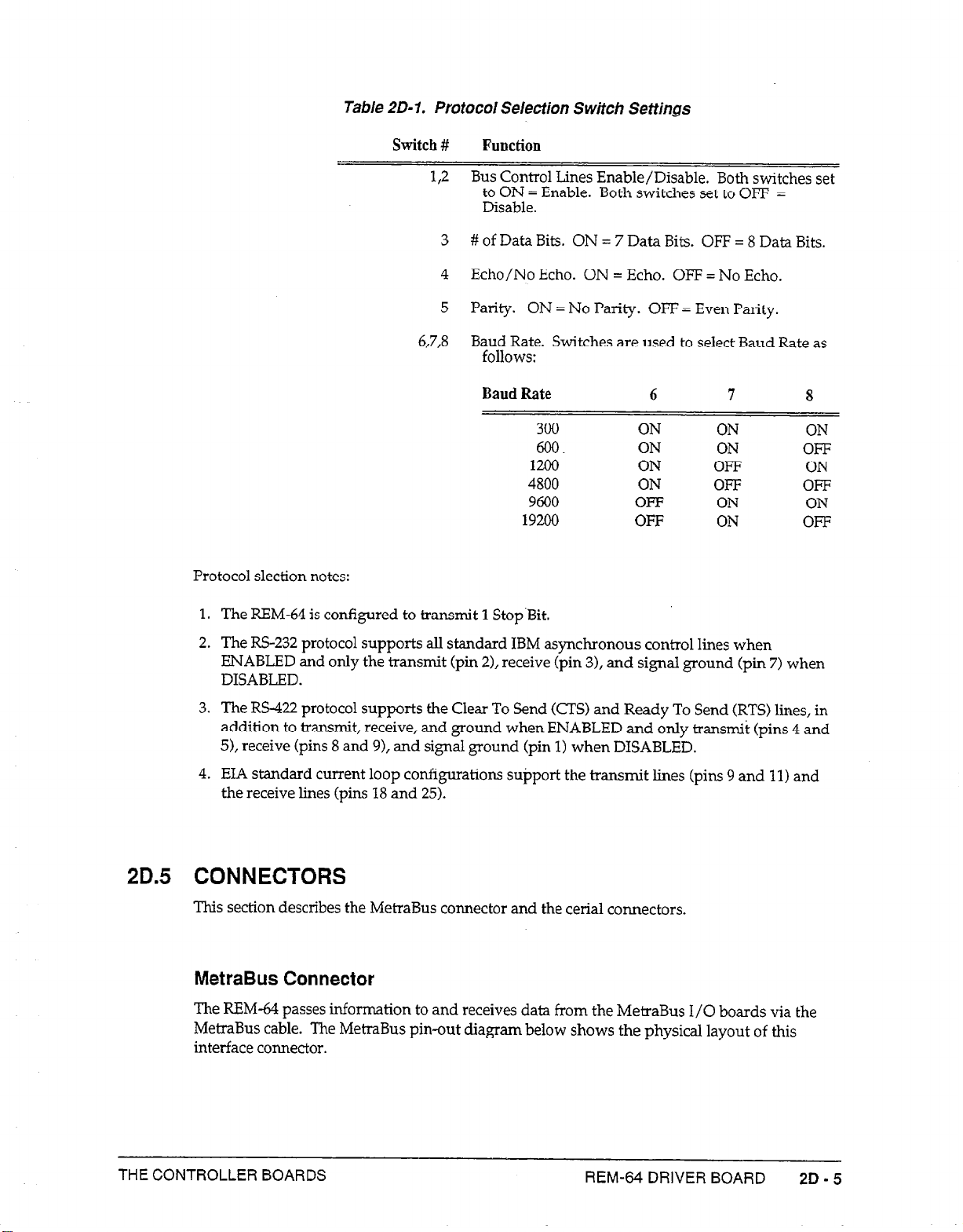
Table 20-l. Protocol Selection Switch Settings
Protocol slection notes:
Switch
# Function
1,2 Bus Control Lines Enable/Disable. Both switches set
to ON = Enable. Both switches set to OFF =
Disable.
3 # of Data Bits. ON = 7 Data Bits. OFF = 8 Data Bits.
4
Echo/No Echo. ON = Echo. OFF = No Echo.
5
Parity. ON = No Parity. OFF = Even Parity.
6,7,8 Baud Rate. Switches are used to select Baud Rate as
follows:
Baud Rate
300 ON
606
1200
4800 ON OFF OFF
9600 OFF ON
6
ON
ON
7
ON ON
ON OFF
OFF
19200 OFF ON OFF
8
ON
ON
The REM-64 is configured to transmit 1 Stop.Bit.
1.
The RS-232 protocol supports all standard IBM asynchronous control lines when
2.
ENABLED and only the transmit (pin 21, receive (pin 3), and signal ground (pin 7) when
DISABLED.
The RS-422 protocol supports the Clear To Send (CTS) and Ready To Send CRTS) lines, in
3.
addition to transmit, receive, and ground when ENABLED and only transmit (pins 4 and
5), receive (pins 8 and 91, and signal ground (pin 1) when DISABLED.
EL4 standard current loop configurations support the transmit lines (pins 9 and 11) and
4.
the receive lines (pins 18 and 25).
2D.5 CONNECTORS
This section describes the MetraBus connector and the cerial connectors.
MetraBus Connector
The REM-64 passes information to and receives data from the MetraBus I/O boards via the
MetraBus cable. The MetraBus pin-out diagram below shows the physical layout of this
interface connector.
THE CONTROLLER BOARDS
REM-64 DRIVER BOARD
2D-5
Page 54

DATA
3X
CONT?C)L
ADDRESS ’
BUS
FOWER i
r-
T-
L
L
m /
-1
DI
52
E3
D-4
D5
33
57
CLEAR
WSTR B
RT
7s
-27
XT
33
ii4
Ti5
BUSY
+I5 v
-15 v
i5 v
4-5 v
45 v
i5 v
+5 v
3
5
7
9 10
:1
1 3
i5
17
19 20
2:
23 24
25
27 28
29 30
3i
33 34
35 36
37 38
39 40
L *,
43
45
47
49
12
14
16
i8
22
26
32
42
44
46
48
50
4
6
8
1
GND.
GND.
GND.
GND.
GND.
GN3.
GN3.
GIN].
GN3.
GNC.
GNG.
GNG.
GNG.
GNC.
SND.
GND.
GND.
GND.
GND.
GND.
+5 v
+5 v
+5 v
+5 v
+5 v i
POWER
Figure 20-5. MetraBus Connector Pinouts
Serial Connectors
The REM-64 driver card contains four serial connectors: two are KS-232 compatible, and two
are for RS-422. Note that your PC may require a null modem, depending upon its serial port
configuration (DTE/DCE). The REM-64 is shipped as Data Terminal Equipment (DTE),
allowing connection of additional REM-&s using standard serial cables. The current loop
communication interface is not multi-drop compatible.
assignments for both the FS-232 and FS422 interfaces.
RS-232 AND CURRENl LOOP RS-422
TRANSMIT DATA (TO) 2
RxEivE DATA (RD) 3
READY TO SEND (R-IS) 4
CLEAR TO SEND (CTS) 5
DAiA SET READY (DSR) 6
SIGNAL GROUhD 7
DATA CARRIER DEECT (DcD) 8
XMli DATA * 9
XMIT DATA - I
18 RCV DATA *
20 DATA T.RA%MlT READY (DTR)
Figure 2D-6 illustrates the pin
SIG GROUND :
RTS- 3
XMIT DATA 4
XMIT DATA- 5
RTS 2
>
0:
0
0 l
5
6 CTS-
7 CTS
8 RCV DATA
9 RCV DATA-
l
- 20 mA CURRENT LOOP
Figure 20-6. Serial Connector Pinouts
2D-6 METRASUS USER MANUAL
25 RCV 3ATA .
Page 55

Multiple REM-64 Connections
Every REM-64 contains two sets each of 135-232 and RS-422 connectors. Each set of connectors
is configured in parallel so that multiple REM-+ may be interconnected. In a typical multidrop wiring scheme, the REM-64.s might be networked in a ‘7”’ type system. A11 REM&s in
the network monitor the serial bus at all times. Only the active REM-64, as targeted by the
board select command, decodes the REM-64 commands and enables those MetraBus I/O
boards connected to it.
2D.6 USE OF THE AUXILIARY POWER SUPPLY
The REM-64 does not draw power from the PC. As a result, an auxiliary power supply such
as Keithley MetraByte’s MBUS-PWR is required to operate
I/O Boards in your system. The use of other supplies is permitted as long as they meet the
MBU!S-PWR specifications. See the MBUS-PWR section of this
installation procedure.
the
REM-64 as well as ail MetraBus
manual
2D.7 INSTALLATION OF THE REM-64
The REM-64 is a serial I/O board specifically designed for use with the MetraBus system. Its
level of serial protocol support is equivalent to the standard IBM PC/XT asynchronous
adapter board. You should bear this in mind when interfacing the REM-64 to other serial
devices (computer, terminals, controllers, etc.). As mentioned earlier, the use of a null modem
(crossing pins 2 and 3) may be required for devices configured as Data Communication
Equipment (DCE) .
for specifications and
Once you have configured your REM-f%, you will want to connect it to the computer and
MetraBus I/O Board(s). The procedure outlined below will aid in the installation of your
REM-&. You should also refer to those sections of this manual that deal specifically
MetraBus I/O boards that you are using for a full discussion of their functionality.
You may want to refer to the serial communication tutorial provided in Appendix A. This
explains the basics of serial communication protocol interfacing.
To instaIl the REM-&i,
Remove power from the computer.
1.
Connect one end of your serial cable W-232 or RS-422 cable) to the computer’s serial port
2.
and secure it using the two smaIl screws on the cable connector. Connect the other end to
one of the REM-64 serial ports. Since each pair of ports is wired in parallel, it doesn’t
matter which port your use. Additional REM-&Is may be connected at any time. Follow
the procedure below for each additional REM-64 being used.
Connect the REM-64 to the first MetraBus cable connector. Make sure that the locking
3.
tabs are indeed locked around the mating portion of this connector.
Unplug the power supply from line current prior to MetraBus cable interconnection.
4.
Connect the MBUS-PWR to a second MetraBus connector.
Connect all other MetraBus I/O boards to the cable.
5.
Repower your computer and plug in the power supply.
6.
with the
THE CONTROLLER BOARDS REM-64 DRIVER BOARD
2D-7
Page 56

NOTE: Two resistor termination networks are shipped with every
REM-64. These resistors should be installed on the MetraBus I/O
board furthest from the REM-&. The sockets RN1 and RN2 are
provided for this purpose.
These resistors minimize signal reflections
due to long cable lengths. They are optional, however, and have little
effect upon cables of 50 feet or less.
2D.8
PROGRAMMING THE REM-64 TO CONTROL THE METRABUS
Programmi ng the REM-64 uses a set of eight simple comman ds. Designed for maximum
power and flexibility while maintaining the elegant simplicity that is evident throughout the
MetraBus line, the REM-64 command syntax provides the user with immediate access to
MetraBus I/O board functionality. The commands
A command interpreter on board the REM-64 detects any transmitted errors in command
syntax, data parameters out of range, etc. and generates an error message describing the type
of error detected. The REM-64 commands are listed in Table 2D-2.
Table 2%).2. REM-64 Commands
Command
B
A
W
R
C
S
H
D
Name
Board Select
Address Pointer
Write Data
Read Data
Clear MetraBus
status
Hex
Decimal
Targets specified REM-64 by Bus Address.
Selects the specified MetraBus I/O Board.
Transmits instructions to the selected I/O board.
Retrieves data from the l/O board via the REM-64
Resets entire
Retrieve current Board Address and status bits.
All dara transmitted and retrieved in Hexadecimal.
All data transmitted and retrieved in Decimal.
The commands are further described below. Note that all of the provided examples are
written in IBM BASICA as irnpIemented on IBM PC/XT and PC AT compatibles. Similar
routines can be written in other languages on other computers.
may
be sent in either upper or lower case.
Function
MefraESus
to power-up status.
2D-8
HINT:
When first writing application programs for the REM-64, it is
good idea to return all data to string variables. This is because typing
errors, illegal parameters, etc. are flagged by the REM-64 and error
messages are
transmitted to the COMM buffer. You will never see
these messages if you assume that integer data should be returned.
Characters that are printed as integers will have a value of zero. This
could cause a great deal of wasted time if you assume that the I/O
boards are not operating correctly. Once the program is working and
debugged, change back to the integer variables.
The “B” Command - Board Select
Before any MetraBus I/O board can be addressed, the REM-64 must be targeted. This is done
using the B command, followed
asynchronous communication board such as Keithley MetraByte’s COM-422 configured as
“COMI” and a REM-64 with an address of 4.
METRABUS USER MANUAL
by the
REM-64 address. The examples assume an
Page 57

When communicating with the REM-64 via the serial communication port on your computer,
the BASIC PRINT # and INPUT # statements may be used to respectively send information to
and receive data from the MetraBus system.
10OPEN "COM1:9600,N,8,1" AS #l
20PRINT #l, "B4" 'Print
Once a REM-64 is targeted, commands may be issued to any MetraBus I/O boards connected
to that REM-64 via the MetraBus cable. The address pointer, write data, and read data
commands (A,W,and R respectively) are used to instruct the various I/O boards connected to
the targeted REM-64 MetraBus cable. These commands are discussed below in order of
common usage.
'Open COMl port Q 9600 baud,
'no parity, 8 data bits, and
'1 .stop bit as FILE #l
"B4" to FILE#I thus selecting
'REM-64 Address 4.
The “A” Comnand - Address Puinfer
The function of the address pointer is to point to a specific MetraBus I/O board. There are 64
available MetraBus I/O addresses that may be “pointed to” by the REM-&L Each MetraBus
I/Q board must have a unique, non-overlapping board address in order to identify it from
other boards in the MetraBus system. (Refer to the section “Setting the board address” for the
relevant I/O board.) Some MetraBus I/O boards use more than one MetraBus address, so
that caution must be exercised when setting a board address. Again, the sections of this
manual delaying with your specific I/O boards should be consulted prior to attempting use of
the REM-64 and I/O boards. Writing the board address to the MetraBus address pointer sets
the current I/O board address and targets that board for use. Once the address pointer is set
to a particular board address, data can be written to or read from the board. The following
example illustrates how to set the address point to the I/O board (an MIA-16, for example) at
address 12.
lOlREH64 =4
2OMAI16 = 12
300PEN "COM1:4800,N,7,1"
40 PRINT #l, "B";lREX64 'Target REX-64 at Addxess 4
50 PRINT #l, "A";MAI16 'Point to MA116 at Address 12
Note that in the above example we have defined the I/O board address as a variable. This is
standard programmin
simple redefinition of the address rather than an entire restructure of the program) with the
routine that follows. This practice will be followed in aI1 examples in order to make them
generally applicable.
Variable declaration is generally done at the beginning of your application program for ease
of access as follows:
lOMEM8=0 'Declare MEM-8 address
2OMAIl = 4 ‘Declare first MAI- address
3OMAI12 = 8 'Declare second MAI- address
Once the MetraBus address pointer is set, it does not change until another A command
changes it.
THE CONTROLLER BOARDS REM-64 DRWER BOARD
g technique since it allows for reassignment of any I/O board (with a
AS
'Declare REM-64 address
'Declare MAI- Board Address
#l 'Open COMl @ 4800 baud, no
'parity, 7 data bits, and 1
'stop bit as file #l
2D - 9
Page 58

The “S” Command - Status
Since the board address is latched on the REM-f& it may be read back using the 5 command
as follows:
90
PRINT #l, "S"
100
INPUT #l, ADDRELSS
The BASIC variable ADDRESS contains the current MetraBus I/O board address.
‘Send Status command to
'target REM-64
'Get data from the
'Communication Buffer
Reading the status returns six bits of address information and
These status bits are
R/W and BUSY as shown below.
two bits
of
status information.
Address Byte
BIT D7 D6
BUSY R/W A5 A4
D5
D4
D3
A3
D2
A2
D-I DO
Al A0
Normally, the BUSY and R/W status bits will be low (zero). (Note that the driver board
inverts the polarity of the actual Bus control signals.) When this is true, the data returned will
be identical to the address. The REM-64 may be used with assembled or compiled languages
with no fear of active status bits since the serial nature of the data transfer in conjunction with
communication buffer
access times are quite slow in comparison to A/D conversion times.
The “w” Command - Write Data
Once the address pointer has been set, data may be written to and read from a MetraBus I/O
board. Writing to the current I/O board involves no more than sending the W command
followed by the data value corresponding to the function to be accessed (see those sections of
this manual dealing with the specific board). The following example accesses an MEM-8
electromechanical relay board and closes switch 3.
2D-10
10=8=4
2OlREM64 = 0
3OOPEZi “COM1:9600,N,7, 1” AS #l.
40 PRINT #l, “B”; l-64
50 PRINT #l,"A";EEM8
60
PRINT #l, “W”; 2A3 ‘Activate
‘Declare MEX-8 Board Address
IDecLare REM-64 at Address 0
'Open COMM port as File #l
‘Select REX-64 at address 0
‘Point to MEX-8
switch 3 of MEM-8
This program outputs a value of 8 (2*3) which closes relay number 3 on the MEM-8 relay
board (see the MEM-8 section of this manual for a complete discussion of MEM-8
functionality).
The “R” Command - Read Data
Reading data from MetraBus input (analog and digital) boards may be accomplished through
the use of the R command. In addition, all MetraBus Output Boards contain a data readback
feature that enables the user to verify transmission of data to the board. This allows for
METRABUS USER MANUAL
Page 59

verification of data integrity which may become important when using a REM-64 at very high
baud rates over long distances or where the MetraBus system is used in an electrically noisy
environment. For example, if. we use the above program and wish to make sure that the
correct relay was closed we could add the following lines of code:
70PRINT #1, "R"
80
INPUT #1, RELAY
'Read data from the MEM-8
‘Get data from the COMM buffer
90PRINT RELAY 'Display data on the CRT
The BASIC variable RELAY will contain data from the MetraBus I/O board previously
targeted by the address pointer. All MetraBus output boards latch data sent to them, and
therefore,
have
data readback capability.
Data may be read from MetraBus input boards in exactly the same way. For example, to read
the status of the inputs lines from a ME-32 digital input board, the following program may be
used:
lOMII32
2OlREM64
30
OPEN "coM1:4800,N,7,1" AS #1
40PRINT #l,"B";lREM64
50 PRINT #l,"A";MII32
=
8
‘Declare MII-32 Board Address
= 1 'Declare REM-64 Address
'Open COMM port as file #l
'Select REM-64 at address 1
'Point to MII-32
60 PRINT #l,"R" 'Send data from MII-32 (block 0)
7OINPUT #l,BLOCKO 'Get data from COMM buffer
80PRSNT BLOCK0 'Display data on CRT
The “C” Command - Clear MetraBus
A software reset causes all MetraBus I/O boards connected to the MetraBus cable to be reset
to a known state. This reset state is described in the section covering each MetiaBus I/O
board.
The following example illustrates use of the software RESET feature for all MetraBus I/O
boards connected to the selected REM-64 MetraBus cable.
lOOPEN "COM1:96OO,N,8,1" AS #1
20 PRINT #1, "B2"
30PRINT #l "C"
,
The “H” and “D” Commands - Hexadecimal and Decimal
These two data format commands can be used to specify whichever data format you are
comfortable with. The power-up/default status is decimal. A subsequent PNNT #l, “H”
command will change this to hex format.
Programming The REM-64 To Control The I/O Boards
As described above, the execution of REM-64 co
pattern when programming any MetraBus I/O board. The following is a brief ovetiew of
programming techniques associated with the various types of I/O boards. The following
examples illustrate programmin
Detailed information concerning programmin
description.
THE CONTROLLER BOARDS
'Open serial COMM port
'Select REM-64 at address 2
'Send system CLEAR command
mmands generally follows a consistent
g techniques used with both digital and analog I/O boards.
g for specific boards can be found in the board’s
REM-64 DRIVER BOARD
ZD-11
Page 60

Digital l/O Boards
Digiti I/O boards are the easiest to control. Data can be written to the board immediately
after setting the address pointer. Digital output boards typically have several &bit ports. In
the following example, a digital output board is at boarda address 4 and the REM-64 is at
address 0.
lOMIO32 = 4 'Declare MIO-32 address
201REM64 = 0 'Declare REM-64 address
300PEN "COM1:9600,N,8,1" AS #1 'Open COMl port as file #1
40 PRINT #l,"B";lREK64 'Select REM-64 at address 0
50 PRINT #1, "A";MI032
60PRINT #l, "W255" ‘Output bit pattern 1111 1111
70CLOSE #l
Lines 10 and 20 declare the address locations of the REM-64 and MIO-32, respectively.
Line 30 opens the serial communications port as file #1 with a data I/O format of 9600 Baud,
no parity bit, eight data bits, and one stop bit.
'Point to MIO-32 at address 4
'Close file #l
Line 40 selects
the
EM-64 declared previously.
Line 50 points to the MIO-32.
Line 60 outputs a value of 255 to the digital output card setting all outputs of block 0 high.
Digital input boards, like digital output board, typically have several &bit ports. After the
address pointer has been set to the MetraBus board address, data can be read from the board
using the R command.
Ln the following example, a digital input board (MII-32, for example) is
at MetraBus address 4 while the REM-64 is at address 2.
lOMII32 = 4
201-64 = 2
3OOPEN
40
PRINT #l, "B"; lREM64 'Select REM-64 at address 2
50
PRINT #l, "A";
~COM1:9600,N,7,1"
MI132
+
AS
2
60PRINT #I, "R"
70
INPUT #l, BLOCK2
'Declare MII-32 address
'Declare REX-64 at address 2
#1 'Open COMl port as file #1
'Point to Block 2 of MII-32
'Transmit data from MII-32
'Retrieve data from COMM buffer
BOPRINT BLOCK2 'Display data on CRT
90CLOSE #1
'Close file #l
Lines 10 and 20 declare the addresses of the MIT-32 and the REM-&L
Line 30 opens the serial communication I/O port as file #1 at 9600 baud,
no
parity, 7 data bits,
and 1 stop bit.
2D-12
Line 40 selects the REM-64 previously declared.
Line 50 points to the MS32.
Line 60 tells the REM-64 to send the data from the MIS32 back to the computer.
Line
70
retrieves this data from the communication buffer.
Line 80 displays this data on the CRT screen.
METRABUS USER MANUAL
Page 61

Analog l/O Boards
Analog output boards use one of the available 64 MetraBus addresses per channel. Setting the
address pointer to the appropriate address and writing data to the board will produce an
analog output. The following exampIe
voltage.
shows
how to set the address pointer and output a
lOMAO = 8 'Declare MAO8 Board Address
202RRM64 = 8
'Declare REM-64 at address 8
3OOPHN "coM1:9600,N,7,1" AS #1 'Open COMM port as fil.e #l
40 PRINT #l, "B"; 2REM64
'Select RHM-64
at address 8
50PRINT #l, "A"; MAO8 + 'Point to channel 3 of MAO-8
60PRINT #l, "Wl92"
70CLOSE #l
'Output corresponding voltage
'Close file #l
Lines 10 and 20 declare MAO-8 and EM-64 addresses. Notice that these addresses are the
same. This is alright since the REM-64 address is essentially an address on the serial bus and
is not related in any way to the 64 available MetraBus addresses.
Line 30 opens the serial communication port as file #1 for data transfer at 9600 baud, no parity
bit, seven data bits, and one stop bit.
Line 40 selects the REM-64 previously declared.
Line 50
points to the MAO-8 .
Line 60 tells the MAO-8 to output a voltage corresponding to the integer 192. (See the MAO-8
description for more
Line 70
and 80 close file #l and end the program.
information.)
Analog input boards require additional steps in order to set the gain and resolution for the
desired channel prior to‘collecting data. -
MA116 = 16
10
lRHM64=1
20
30 OPEN "COM1:9600,N,7,1" AS #l
40
50
PRINT #l,
PRINT #1,
"B";lREM64
"A";
MAI16+2
60 PRINT #1, "W";l8
PRINT #I, "A'&; MA116
70
PRINT #l,"WOO"
80
PRINT #l, "A";MAI16
;:O PRINT #l
II R"
110 INPUT #l: LSB
120 PRINT #l, "A"; MA116
130 PRINT #l, "R"
140
INPUT
#l, MSB
150 CLOSE #l
160 AIN=MSB*16 + LSB/lB
'Declare MAI- address
'Declare REM-64 at address 1
'Open COMM port as file #1
'Select REM-64 at address 1
'Point to GAIN/CH selection mode
'Set gain to +/-
5V range on Ch 2
'Point la-bit conversion mode
'Starts la-bit A/D conversion
'Point to data LSB's
'Read data back to COMM buffer
'Store data
in variable
LSB
'Point to data MSB's
'Read data
back to CONM buffer
'Store data in variable MSB
'Close file #l (COMM port)
'Combine
bytes
to
form data
value
170 PRINT AIN
Lines 10 and 20 declare MAI- and REM-64 addresses.
Line 30 opens the serialcCommunication port as specified parameters.
Line 40 selects REM-64 at address 1.
THE CONTROLLER BOARDS REM-64 DRIVER BOARD 2D-13
Page 62

Line 50 points to GAIN/CH select mode of MAI-16.
Line 60 sets the gain to +5 V on channel 2.
Line 70 points to 12-bit conversion mode of MAI-16.
Line 80 starts the A/D conversion process.
Line 90 points to LSB data from the A/D conversion process.
Line 100 reads the LSBs back to the computer COMM buffer.
Line 110 gets the data from the buffer and stores it is a variable LSB.
Line 120 points to MSB data from A/D conversion process.
Line 130 reads the data MSBs back to the computer COMM buffer.
Line 140 gets the data from the buffer and stores it in variable MSB.
Line 150 closes file #l (the COMM port).
Line 160 combines the LSBs and MSBs to form a single data byte.
Line 170 displays the data on the CRT screen.
There is a good deal of redundancy in the above routine that would normally be ehrninated in
actual usage. It is shown here only for the sake of step-by-step instruction. See the MAI- for
details concerning the various functions on the board.
Using Compiled & Assembled Languages With The REM-64
The use of compiled and assembled languages requires no special precautions when used
with the REM-64 since even at very high data transfer rates (19,200 baud) the serial nature of
the data transfer combined with buffer access times are magnitudes slower
conversions. When using the IEM-64, we are, therefore, not “taIking” directly to it or any of
the I/O board but must pass through this data buffer. You can see that with very fast
program execution times i.e., compiled. or assembled programs, you are actually monitoring
the status of the communication buffer and not I/O board activity. The S command
(STATUS) is implemented for address verification and for future use as far as the status bits
are concerned.
NOTE: If your data-monitoring routines attempt to write data or
commands to the MBB-32 while the circuitry is busy, problems will
arise. Therefore, when gathering data from slow circuitry, design your
data collection routines so that they actually retrieve data and/or polI
the BUSY bit using the S command prior to assuming that no data has
been produced.
Generally, it is a good idea to have the computer
simply time-out while waiting for data from the COMM buffer.
IBM DOS manual for further information concerning time out
definition.
than
most A/D
See the
2D-14
METRABUS USER MANUAL
Page 63

Chapter 3: The Power Supply Boards
3A.1 GENERAL
The PWR-55 and PWR-100 are auxiliary power supplies for the MetraBus industrial data
acquisition and control system. These boards are predecessors to the newer MBLJS-PWR
board (see Chapter 3, Part B). The Pm-55 and PWR-100 supply required power for all
MetraBus I/O boards. When a PWR-55 /PWR-100 is used, the only power drawn from the
host PC is for the MetraBus controller/driver card. Both the PWR-55 and the PWP-100 are 19”
rack-mountable in either a standard NEMA type enclosure or the MetraByte RMT-02.
The PWR boards furnish +5 VDC, +15 VDC, -15 VDC, and ground signals on the MetraBus
cable. PWR-55 is 55 W supply, PWR-100 power is 100 W. Either board must match the
anticipated power draw of your MetraBus system. Both supplies contain AC line filters that
exceed IL478 and UL1283 specifications and comply with UL, VDE, CSA, and IEC safety
standards.
NOTE: Connect only a single power supply to a single MetraBus
cable. For a MetraBus requiring more than 100 watts of power, contact
the factory for assistance.
Part 3A
PWR-55/PWR-I 00 BOARDS
Input voltages of 90 to 125 VAC or 180 to 250 VAC along with input frequencies of 45 to 65 Hz
(4
to -63 Hz for PWR-100) allow the use of both U.S. and European standard line current. The
PWR-55 works with either 110 or 220 VAC interchangeably, while the PWR-100 requires a
jumper change for 220 VAC operation. The jumper is clearly marked on the board. The
supplies are approximately 65% efficient while providing 4000 Vrms of isolation from
standard 120/220 VAC lines. The PWR-55 and the PWR-100 are switching type supplies with
hold times of 16 ms (20 ms for the PWR-55). Both supplies feature a soft start mode, are
current limiting and have linear regulation on all outputs. Extra line filters and optional
power capacitors are available for various applications. Contact the factory (See Chapter
for further details concerning those applications that may require these power options.
Certain MetraBus I/O boards require the use of either power supply. Any system using the
MID-&l, or REM-64 interface/driver cards, the MAI- analog input board, the MAO-8 analog
output board, certain configurations of the MCN-8, and any MetraBus system that draws
more than 2 Amps will require the use of an auxiliary power supply.
3A.2 FEATURES
l
Plugs into any MetraBus cable connector
l
Meet UL, VDE, IEC, and CSA approval
l
90-120 VAC or 180-250 VAC switch selectable
21.)
l
Isolation to 4000 Vrms
THE POWER SUPPLY BOARDS
PWR-55/PWFi-100 BOARDS
3A-1
Page 64

l
AC line filter built-in
l
Status LEDs and multiple test points
l
Convection cooled
l
45-65 Hz (47 - 63 Hz for PWR-100) input allows European voltages
3A.3 SPECIFICATIONS
Input Voltage:
90
to 130 VAC
180 to 250 VAC
Input Frequency:
Isolation:
Operating Temperature:
Hold up Time:
Output Ratings:
MetraBus Cable Type:
MetraBus Connector:
47
to 63 Hz (45 to 65 Hz for PWR-55)
4000 vrms
0 - 70” C (derate 2.5% per degree over 45” C)
16 ms (20
5 VDC @ 12
+15 VDC @ 3
-15 VDC @ 3
ms for PWR-55)
A (5 A for PWR-55)
A (2 A for PWR-55)
A (2 A for PWR-55)
50-conductor ribbon cable.
3M 3425-6050
3A.4 INSTALLING THE PWR-55/PWR-100
Using the PWR-55 or PWR-100 requires a line cord with a plug for the avaiIable type of power
(110/220 VAC). The cord should be long enough to reach from the wall outlet to the
MetraBus cable.
NOTE: Perform the following procedure only under no-power
conditions.
1.
Visually inspect the PWR-55 or PWR-100 for loose wires, screws, or components.
2. Secure the three line wires to the line input terminals u2) of the PWR-55/PWR-100 and
replace the plastic cover for protection. Be sure to install the green earth-ground line.
3. Select an unused MetraBus cable connector and plug the power supply into the cable,
making certain that the locking tabs on the connector are locked around the mating
portion. The connectors are keyed for your protection. Check the keyways for correct
alignment prior to plugging them together. Avoid the use of force with these connectors.
4. Plug the line cord to a source of power.
3A.5 USE OF OTHER POWER SUPPLIES
3A - 2
You may use power supplies other
PWR-55/PWR-100 specifications.
METRABUS USER MANUAL
than
the PWR-55/PWR-100 so long as they supplies meet
Page 65
3A.6 THE MTAP-1
The MTAP-1 is a power break-out board for the MetraBus system. The board can bring power
to the MetraBus from an
supply to support user circuitry. Three LEDs show power supply status. A green LED lights
to show that +5 V power is on, while red and yeflow LEDs display power
+15 V and -15 V supplies, respectively.
A 3 X 1.5 inch breadboard area is included on the board to facilitate the installation of user
circuitry. Terminal posts connected to the power supply inputs are at the edge of the
breadboard area.
The MTAP-1 provides direct connections to the power distribution conductors in the cable.
To power a MetraBus system with an external power supply, plug the MTAP-1 into the
MetraBus cable and connect the supply inputs to their corresponding screw terminals on the
MTAP-1.
Do not connect
containing a PWR-55 or PWR-100 board of that has Fuse FI installed
on an MDB-64.
external
external
supply or can extract power from the MetraBus power
on
conditions for
CAUTION
power supplies to any MetraBus system
THE POWER SUPPLY BOARDS
PWR-55/PWR-100 BOARDS
3A-3
Page 66

Q
Q
3A-4 METRAEWS USER MANUAL
Page 67

Chapter 3: The Power Supply Boards
Par-t 3B
MBlJS-PWR BOARDS
GENERAL
The MBUS-PWRs are auxiliary power supplies for the MetraBus industrial data acquisition
and control system. A 120 VAC version is for use in North America and carries a /NA
designation; similarly, a 220/240 VAC version is-intended for the European market and
carries a /EURO designation. Both versions are 19” rack-mountable in either a standard
NEMA type enclosure or the MetraByte RMT-02 frame. Both versions also meet applicable
IEC, UL, CSA, and VDE safety requirements. MBUS power supplies are replacements for the
PWR-100/55 and provide multiple supply operation.
The MetraBus power distribution system is modular to accommodate the needs of small and
large systems. This feature allows you to
without limiting the size of the system.
system, you must first estimate the power load on the basis of your intended board
complement. The three basic power distribution systems are PC power, single power supply,
and multiple power supplies.
minimize the cost of power supply components
However, in configuring the power distribution
For a small system that will use only digital boards requiring under 2 A of +5 VDC power, the
PC can power the boards directly. In this configuration, you must install fuse Fl(1 A) on the
MDB-64 driver board for the PC to power the digital boards. Boards such as the MID-64,
REM-&, MAI-16, MAO-8, and the MCN-8 require +15 or -15 VJX and must use an MBLJSPWR board. A typical small system configuration is depicted in Figure 3B-1.
1 PC
MDB-64
-i5
VDC
Figure 3B-I. Small System
In a medium-size system, where the power load is under 100 W, attach an MBUS-PWR board
to the MetraBus cable. Remove Fuse Fl from the MIX-64 board, and plug the cable into
either power connector of the MBUS-PWR board.
MBUS-PWR board to further daisy-chain I/O boards. For even power distribution under
near-full loads, place the MBUS-PWR board in the middle of the daisy chain, as shown in
Figure 3B-2.
Use the other power connector of the
+
I/O BOARD
THE POWER SUPPLY BOARDS
MBUS-PWR BOARDS
3B-1
Page 68

KID-64
ND&64
I/O I/O
BOARD
-z-
-zm
?OVW
I
POWW
BOARD
Figure 3B-2. Medium System
In a system whose expected power draw is beyond 100 W, use multiple MBUS-PWR supplies.
Connections for -multiple MBUS-PWR boards utilize the expansion (EXP) connectors, as
shown in Figure 3B-3. These connectors pass the communication signals to the next set of I/O
boards but isolate the power distribution structure. The MBUS-PWR power (PWR)
connectors supply system power to the ribbon cable. Be sure to properly estimate the load of
each group of I/O boards, and do not connect the PWR connectors of any two MBUS-PWR
boards.
Y&Y-
3B.2 FEATURES
* Plugs into any MetraBus cable connector
* Designed to meet UL, VDE, IEC, and CSA requirements
0 90 to 120 VAC or 180 to 250 VAC versions
* AC line filter built-in
l
Power Status LEDs
l
Convection cooled
3B.3 SPECIFKZATIONS
Input Voltage:
Input Frequency: 47 to 63 Hz
--XL-
Figure 3B-3. Large System
90
to 132 VAC
180 to 264 VAC
CRoYUF
Operating Temperature:
Hold up Time:
Output Ratings: 5VDC@15A
MetraBus Cable Type:
3B-2 METRABUS USER MANUAL
0 to 70” C (derate 2.5% per degree over 50” C)
2orns
+15VDC@4A
-15.VDC@l A
50-conductor ribbon cable.
Page 69

MetraBus Connector:
Status Indicators: +5, +15, -15 V available (green LEDs)
3M 3425-6050
Terminal Blocks:
Output Ground Jumper: Float or utilities ground
+5, +15, -15
V and common
3B.4 INSTALLATION
NOTE: Perform the following procedure only under no-power
conditions.
Visually inspect the MBUS-PWR for loose wires, screws, or components.
1.
Determine the power distribution configuration and connector utilization.
2.
Select an unused MetraBus cable connector and plug the power supply into the cable,
3.
making certain that the locking tabs on the connector are locked around the mating
portion. The connectors are keyed for your protection. Check the keyways for correct
alignment prior to plugging them together. Avoid the use of force with these connectors.
Plug the line cord to a source of power.
4.
5.
Turn on power switch.
3B.5 USE OF OUTPUT GROUND JUMPER
To provide maximum flexibility and minimize ground loops within multiple-supply systems,
MBUS-PWR boards contain an output ground jumper.
utilities chassis ground directly to the DC common of each supply. Such a connection in no
way affects the chassis ground of the supply itself.
system noise by floating all output commons except one-to remove ground loop paths.
3B.6 THE MTAP-I
The MTAP-1 is a power break-out board for the MetraBus system. The board can bring power
to the MetraBus from an external supply or can extract power from the MetraBus power
supply to support user circuitry. Three LEDs show power supply status.
3B.7 THE MBUS-PWR CONNECTORS
The MBLJS-PWR connectors allow you to split the power distribution in a MetraBus system
between multiple power supplies. Using the expansion connector passes the bus and control
signals but isolates the power structure.
If desired, this jumper can connect the
In most cases, you will elect to minimize
THE POWER SUPPLY BOARDS
MBUS-PWR BOARDS 38-3
Page 70

DATA
BUS
CONTROL
A3DRESS
BUS
POWER
Z
til
r
E
m
G
is
rsi
L-
D
CLEAR
WSiRa
C
m
- ti
-3
72
w
XZ
i w
BUS'I
- +15 v
-15 v
I t5V
+5 v
i5 v
+5 v
+5 v
POWER CONNECTOR
3
5 6
7
9 i0
11
13
15 16
17 it3
19
21
23 24
25
27
29
3i 32
33
35
37
30 40
4:
43
45
47 48
49 50
i
Jl. J3
2
4
a
12
14
20
22
26
28
30
34
36
38
42
44
46
GNC.
GND.
GND.
GND.
GND.
GND.
GND.
GND.
GND.
GND.
GND.
GND.
GND.
GND.
GND.
GND.
GND.
GNO.
GNC.
GND.
+5 v -+5v 1
+5 v
c5 v
c5 v
J
PI
N-OUT
( POWER
CONTROL /
ADDRESS 1
BUS
F- CLEAR
WSiRB
L- VW
r 2
72
x3
EXPANSION CONNECTOR PIN-OUT
Figure 38-4. MBUSPWR Connector Pin Assignments
1 2
3 4
5 6 :
7 8
3 70
11 ;2 :
i 4
13
15
16
i7
18
19
20
21
22
23
24
25
26
27
28
29
30
3:
32
34
33
35
36
38
37
40
39
41
42
44
43
45
46
47
48
49
50
J2, J4
GND.
GND.
GND.
GND.
GND.
GND.
GND.
GND.
GND.
GNO.
GND.
GND.
GND.
GND.
GND.
GND.
GND.
GND.
GNC.
GND.
3B-4
METRABUS USER MANUAL
Page 71

MDI-1 G/MSS-16 SOLID STATE SWITCHING I/O SYSTEM
4.1 GENERAL
The MDI-X/M!%16 is a moduIar 2-board system providing complete optical isolation for
both high and low power switching applications. Each MDI/MSS-16 monitors and controls
16 individual I/O points via optically isolated solid-state, plug-m modules. A variety of these
modules is available for both input and output. Voltages of 120/130 VAC, 0 to 60 VDC, etc. as
weU as standard European line voltages may be sensed and controlled. Control and sense
modules are also usable on a single MSS16. Screw terminals on the MSS-16 accept 12 to 22
AWG wire.
The MDI-16/M%-16 connects directly to any of the MetraBus controller/driver cards through
the MeiraBus cable. You may install
MDI-16/M%-16 combination adjacent to its point of use for easy signal connection.
The MetraBus cable carries aII data, address, and status information, and it distributes power
on the MetraBus. A tot4 of 20 ground lines interleaved among the data and address lines
ensure noise immunity. The MetraBus system allows MetraBus cable lengths of up to 100 feet.
Remote control of the MeiraBus system is possible via the REM-64 serial driver card at
distances of 1.2 km. The MDI-lGR/MSS-16 is 19” rack-mountable in either a standard NEMA
type enclosure or the MetraByte RMT-01. The MDI-16/M%-16 mounts on
other flat surface.
Chapter 4
the
driver card in your computer while positioning the
any
flat panel or
A total of 32 MDI-16/M%-16s can connect to a single MeiraBus cable, allowing monitoring
and control of up to 512 individual I/O points. Like other MetraBus I/O boards, the MDIX/M%-16 has a data read-back aBowing the user to verify data integrity in date output
modes.
For applications requiring more power
power supplies is available.
Some common uses of the MDI-16/M%-16 include computer control of Pump Cychng,
ON/OFF Motor Control, Energy Management, Signal Multiplexing, alarm Activation,
Temperature Cycling, Product Life Cycle testing, etc.
4.2 FEATURES
l
Interfaces directly to IBM PC/XT/AT and compatibles
l
Remote signal connections
l
Senses/Controls up to 512 I/O points per computer expansion slot
l
Extremely cost effective
l
Adapts to your changing requirements
l
Optically isolated to 1500 VDC (nominal)
THE DIGITAL i/O BOARDS
than
your PC can deliver, a choice of auxiliary
MDI-1 G/MSS-I 6 BOARDS
4 - 1
Page 72

4.3 SPECIFICATIONS
Number of I/O ChanneIs:
16
Isolation Type:
Isolation Rating:
I/O Module Life Expectancy:
I/O Modules Installed:
MetraBus Cable Type:
MetraBus Connector:
Environmental
Operating Temperature:
Storage Temperature:
Power Consumption
Physical
+5vDc:
Size:
Optical
4000
Vrms typical
Infinite
None (must be ordered separately)
50-conductor ribbon.
3M 3425-6050
0 to 70” c
-40 to loa0 c
325
n-4 (typical); 40 mA maximum
14.5 x 3.5 inches (MSS-16)
5.0 x 3.5
inches (MIX-16)
4.4 USING AN AUXILIARY POWER SUPPLY
You may power a single MDI-16/M%-16 from the PC power supply since only +5 VDC is
required. However, if you have more than one combination board in your MetraBus system
or if you have other MetraBus I/O boards, an auxiliary power supply may be required. See
the MBUS-PWR sections of this manual for specifications and installation procedure.
NOTE: If you use an auxiliary power supply in conjunction with an
MlX-64 MetraBus Controller/Driver card, remember to remove Fuse
Fl from the MDB-64.
If you use an internal power supply, be certain that the links at each end of the edge connector
of the MSS-16 are installed. You may power the MDI-16/M%-16 with an external +5 VDC
supply by removing the Links and connecting the supply to the two-position power supply
barrier block on the MSS-16.
4.5 CONFIGURING THE MSS-16
The MSS-16 is a standard PB16A mounting rack for solid-state, I/O plug-m modules. Each
MSS-16 wiIl hold up to 16 solid-state I/O modules, which are available in several different
versions and may be ordered from Keithley MetraByte or several other manufacturers. When
ordering I/O modules from other manufacturers, bear in mind that the MSS-16 uses +5 VDC
4-2 METRABUS USER MANUAL
Page 73

for module activation. A
foIlows.
short
list of the various I/O modules available for the MSS-16
VAC OUTPUT (control)
OAC5 - 120 VAC @ 3 Amps
OAC5A - 240 VAC @ 3 Amps
OAC5A5 - 120/240 VAC @ 3 Amps (normally closed)
VAC INPUT (sense)
IAC5 - 120 VAC/DC @ 11 mA
IAC5A -240 VAC/DC @ 6.5 mA
VDC OUTPUT (control)
ODC5 - 60 VDC @ 3 Amps
ODC5A-2OOVDC@lAmp
VDC INPUT (sense)
IDC5-10to32VDC@25mA
IDC5B - 4 to 16 VDC @ 45 mA (fast switching)
NOTE:
may open in
The MSS-16 contains 5 A miniature replacement fuses that
the event of external circuit failure.
4.6 INSTALLING THE MDI-16
The MDI-16 adapter board is available in two versions. The difference between versions is the
placement of the edge connector. The MDI-16R is a right-angle version of the MDI-16. The
MDI-16R was specificaIIy designed to aUow mounting of the two-board combination in a 19”
rack mount (a depth of 5” is required). Our RMT-02 is a straight inhne version with an overaIl
length (including the MSS-16) of 19 l/4 inches. It is commonly mounted on a flat panel of at
least 20” or it may be mounted in 24” racks.
Each MDI-X/M%-16 combination connected to a single MetraBus cable must be set to a
unique, non-overlapping MetraBus I/O board address. Each MDI-16 uses 2 of the available
64 MetraBus addresses. These are consecutive locations starting
Setting the board address is outlined below (Figure 4-l shows a typical board address switch
setting).
Prior to installing the MDI-16/MSS-16, make certain that a MetraBus controller/driver board
has been installed. These boards are described in the first section of this manual.
from the
board address.
THE DIGITAL l/O BOARDS
MDI-16/MSS-16 BOARDS
4 - 3
Page 74

32 I 6 8
Figure 7-l. Setting the Board Address
To set the board address,
1. The board-address DIP switch is located in the lower left comer of every MDI-16. The
numbers silk-screened above the switch indicate the value of the switch immediately
below it. The numbers have value only in the ON position.
2.
Select an unused board address and turn ON those switches corresponding to the address
that
you
have chosen.
corresponding values of 8 and 16 would be ON while the others would remain OFF. It is
important to remember that each MDI-16 must be set to an unused, non-overlapping
Board Address in order to avoid address conflicts when being targeted by the driver card.
3.
After
setting
connect the MDI-16 to the MetraBus driver card via the MetraBus cable. The MetraBus
cable connector is keyed for your protection and should plug in easily. Check the
key-ways for correct alignment prior to plugging in the MetraBus cable.
4. If you have only one MDI-16 or if one of your MDI-16s is the last board in your system,
you should install the resistor terminating networks that are provided with your driver
card. The sockets marked RN1 and RN2 immediately above the MetraBus connector are
for this purpose. These resistor networks are used to minimize signal reflection due to
long cable lengths. They are optional, however, and have little effect for cables of 50 feet
or less.
the board address, you may connect the MIX-16 to the MSS-16. Then,
For example, in order to set a board address of 24, switches with
4.7 PROGRAMMING THE MDI-16/MSS-16
MDI-16 progr
alI necessary control signals are automatically generated within the driver board, the user
need not be concerned with control registers, PEEKing or POKEing memory locations, shifting
bits, PUSHing or POPing stacks, learning new languages, or other system level headaches.
Refer to the driver board descriptions provided in Part 1 of this manual.
amming is very simple due to MetraBus supervision by the driver board. Since
Two programs (in BASIC) are included on the MetraBus diskette. In one, MSSlG.BAS loops
through and sequentially activates each I/O module while displaying the status of all I/O
modules on the CRT su-een. The second program illustrates the BASIC OR command for
4-4 METRABUS USER MANUAL
Page 75

activating I/O modules while maintaining the status of the present module configuration.
The programs link back and forth for easy access. They are heavily commented so that even
the beginning programmer should have little, if any, trouble following the flow of logic
within. These, in conjunction with the examples below, should answer most of the question
that
arise concerning MIX-16/M%-16 usage.
MDI-16 Terminology & Data Format
Like all MetraBus I/O boards, there is a standard programmin
g sequence that is followed
when controlling the MDI-16/M%-16. This sequence consists of the following:
Targeting the MDI-16 via the ADRPTR.
1.
Sending a data value (corresponding to the I/O modules to be accessed) to the DATAIO.
2.
MetraBus treats the 16 modules on the MSS-16 as two @-bit) blocks corresponding to two
MetraBus I/O addresses. The data format for each of the two blocks is the same and
corresponds to the folio-wiig:
BIT D7 D6 D5
CH7 CH6
CH5
D4
CH4
D3 D2 Dl
CH3
CH2 CHl
DO
CHO
Because of this arrangement, control of the various I/O modules on the board is accomplished
by writing a single byte whose value is associated with the modules to be accessed. For
example, to activate module #4 on block 0, write a data value of 16 (24 = 16) to
the
DATAIO.
Similarly, if we wanted to activate modules #3 and #5, we would write a value of 40 (23 + 25 =
40) to the DATAIO. To access module 3 of block 1 (relays 8-151, target block one via the
ADRPTR and write a data vaIue of 8(23 = 8) to the DATAIO. This arrangement
makes
it a
very simple matter to specify modules using a BASIC integer variable as shown in the
examples below.
The BASIC OUT and lNP commands are used to respectively send information to and receive
information from the MetraBus I/O board. While the examples are in BASIC, they are equally
applicable to many other computer languages supporting data I/O operations such as C,
PASCAL, Assembly, and others. The following examples assume a MetraBus driver card is
installed at base address 768 (3OOh) and an MDI-16/M%-16 at board address 20.
Example 1
This example illustrates the use of a BASIC variable to sequentially access each relay on the
MSS-16.
lODATA = 768
20ADRPTR = 769
30MSS16 = 20 'Declare MSS-16 Boaxd Address
4OOUT ADRPTR,ESSS16
50
FOR
600uT DATAIO. 2hI
70NEXT I
THE DIGITAL I/O BOARDS
I= 0 TO 7
‘Declare Data I/O location
‘Declare Address Pointex location
'Point to MSS-16 at address 20
'Begin BASIC control loop
'Sequentially close each relay
'End control loop
MDI-16/MSS-16 BOARDS
4 - 5
Page 76

Example 2
Reading back the data value sent to the MSS-16 can be very useful for detecting data
transmission errors. Such might be the case if you are transmitting data over long distances at
high baud rates or if you are in an area of excessive electrical noise.
illustrates the data read-back feature. For the sake of clarity, the above program will be used
with lines added only as necessary.
The following program
1ODATAIO = &H3OO
ZOADRPTR = 769
30MSS16 = 20
40OUT ADRPTR,MSS16
50
FOR I= 0 TO 7
6OOUT DATAIO, (2*1)
70RLYCHK=INP(DATAIO)
80
IF RLYCEX <> (2*1)
90
100 NEXT I
THEN PRINT "ERROR" :END
'Declare Data I/O location
'Declare Address Pointer location
'Declare MSS-16 Board Address
'Point to HSS-16 at address 20
'BASIC control loop
'Activate "1" relay
'Get data just written
'Data integrity check
'Close control loop
110 END
Example 3
It is often useful to be able to activate a relay while leaving the others intact, regardless of their
state. The most efficient way to do this is to read back the state of all relays then OR those
relays with the new relay to be activated.
lODATA = 768
20ADRPTR = 769
3OKSS16 = 20
4OOuT ADRPTR,MSS16
5OINPuT "NEW RELAY II; RLY
6ORLYSTAT
= INP(DATAI0)
7OOUT DATAIO, (2ARLY) OR RLYSTAT
80GOT0 50
'Declare Data I/O location
'Declare Address Pointer location
'Declare MSS-16 Board Address
'Point to MSS-16 at address 20
'Get user input for new relay
'Read back current status of
'relays
'Activate new relay leaving the
'old ones the way they were
'Loop-back
for
next relay
4-6 METRABUS USER MANUAL
Page 77

Chapter 5: The Reiay Boards Part 5A
MEM-8 ELECTROMECHANICAL RELAY I/O SYSTEM
5A.l GENERAL
The MEM-8 is an 8-channe1, double-pole, double-throw (DPDT) electromechanical relay board
designed for use with the MetraBus industrial data acquisition and control system. As
shipped, the board contains eight electromechanical relays with the silver-button type
contacts rated for 100 thousand operations at load (120 VAC/28 VDC at 5 A resistive). The
relays are configured with two poles normally open and two poles normally closed when in
the OFF state. Unlike solid-state relays, electromechanical relays offer zero-current leakage
when OFF. Since the MEM-8 uses industry-standard R10 type plug-in relays, it accepts
substitutions with other relays having contact ratings of your choice. There are also
provisions for relays with other than the standard 5 VDC coils (see the section describing
alternative relays). Figure 5A-1 is a block diagram of the MEM-8.
“CO--*”
NC - A
NO - 6
C-B
NC - B
COAOS
NO - A
C-A
NC - A
NO - B
C-B
NC - B
Figure 5A-1. MEM-8 Block Diagram
Screw terminals on the board will accept 12 to 22 AWG wire. The MEM-8 is 19” rackmountable in either a standard NEMA type enclosure or Keithley MetraByte’s R-MT-02 remote
enclosure. T’he MEM-8 may also be mounted on any flat panel or other flat surface.
The MEM-8, like other MetraBus output boards, has a data read-back feature allowing the
user to verify data integrity. Each relay on the MEM-8 also has-an annunciator LED
associated with it so that visual verification is given when the relay is active. Upon power-up
and MetraBus system CLEAR, all relays return to the INACTIVE state.
The MEM-8 connects directly to any of the available MetraBus driver cards via a 50-conductor
ribbon cable. This MetraBus cable carries all data, address, and control signals as well as
distributing power on the MetraBus. The MEM-8 may be positioned adjacent to its point of
use (up to 100 feet from the computer) for easy signal connections.
Because of its design, the MetraBus system is capable of controlling up to 512 relays (64 MEM-
8s) per computer expansion slot. For those applications requiring greater power than is
available from your computer supply alone, a choice of auxiliary power supplies is available.
THE RELAY BOARDS
MEM-8 BOARD
5A-1
Page 78

Various relay types may be mixed and matched within the same MEM-8 or the board may be
dedicated to a single relay type making this the most versatile, cost effective relay switching
board available.
Uses of the MEM-8 include computer control of pump cycling, ON/OF?? motor control,
energy management, signal multiplexing, alarm activation, temperature cycling, and much
more.
5A.2 SPECIFICATIONS
Relays
Quantity and Type:
8 DPDT
Contact
Material and Type:
Contact Rating:
Operate Time:
Release Tune:
Relay Life Expectancy
Mechanical:
Electrical:
Environmental
Operating Temperature:
Storage Temperature:
Power Consumption
Isolation:
+5vDc:
Silver-cadmium oxide buttons
5 A at 120 VAC (resistive)
5 A at 28 VDC (resistive)
30 ms maximum
10msmaximum
100 miLlion
100 thousand operations (at load)
1000 vnns
0 to 70” C
-40 to 100” C
120 rnA (+180 mA per relay)
operations
Physical
MetraBus Cable type:
MetraBus Connector:
w-2 METRABUS USER MANUAL
Size: 16 x 4.74 inches
Weight:
11.5 oz (326 g-m)
5O-conductor ribbon cable
3M 3425-6050
(40.63 x 12.06 cm)
Page 79

5A.3 USING AN AUXILIARY POWER SUPPLY
You may power one MEM-8 from the PC power supply, since only +5 VDC is required.
However, if you have more
than
one combination board in your MetraBus system or if you
have other MetraBus I/O boards, you may require an auxiliary power supply. See the MBUS-
PWR chapter of this manual for specifications and installation procedure.
NOTE: If an auxiliary power supply is used in conjunction with an
MDB-64 MetraBus Controller/Driver card, remember to remove fuse
Fl from the MDB-64.
5A.4 SETTING THE MEM-8 BOARD ADDRESS
Each MEM-8 connected to a single MetraBus cable must be set for a unique, non-overlapping
MetraBus I/O address if the driver card is to target that specific MEM-8. Setting the board
address is outlined below.
Figure 5A-2 shows a typical board address switch Setting.
8
32 :6
r
1
2 3
L. 2
4 5
6
1
I
Figure 5A-2. Setting the Board Address
To set the board address,
The board address DIP switch is located in the lower-left side of the board just above the
1.
MetraBus connector. The numbers silk-screened above the switch indicate the value of
the switch immediately below it.
Select an unused board address and turn ON those switches corresponding to the address
2.
The numbers have value only in the ON position.
that you have chosen. For example, in order to set a board address of 24, switches with
corresponding values of 8 and 16 would be ON while the others would remain OFF. It is
important to remember that each MEM-8 must be set to an unused, non-overlapping
board address in order to avoid address conflicts when being targeted by the driver card.
After setting the board address, connect the MEM-8 to the MetraBus driver card via the
3.
MetraBus cable. The MetraBus cable connector is keyed for your protection and should
plug in easily. Check the keyways for correct alignment prior to plugging in the
MetraBus cable.
NOTE: It is always good practice to remove power from the
MetraBus cable prior to connecting any I/O boards.
If you have only one MEM-8 or if one of your MEM-8s is the last board in your system,
4.
you should install the resistor terminating networks that are provided with your driver
card. The sockets marked RN1 and RN2 immediately above the MetraBus connector are
for this purpose. These resistor networks are used to minimize signal reflection due to
long cable lengths. They are optional, however, and have little effect for cables of 50 feet
or less.
THE RELAY BOARDS
MEM-8 BOARD 5A-3
Page 80

5A.5 PROGRAMMING THE MEM-8
MEM-8 programrnin g is very simple due to MetraBus supervision by the driver board. Since
all necessary control signals are automatically generated within the driver board, the user
need not be concerned with control registers, PEEKing or POKEing memory locations, shifting
bits, PUSHing or POPing stacks, learning new languages, or other system level headaches.
Refer to the driver board destiptions provided in Part 1 of this manual.
Two programs (in BASIC) have been included on the MetraBus diskette. MEM8.BAS loops
through and sequentially activates each relay while displaying the status of all relays on the
CRT screen. The second program illustrates the BASIC OR command for activating relays
while maintaining the status of the present module configuration. The programs are heavily
commented so that even the beginning programmer should have little, if any, trouble
following the flow of logic within. These, in conjunction with the examples below, should
answer most of the question that arise concerning MEM-8 usage.
MEM-8 Terminology and Data Format
Like all MetraBus I/O boards, there is a standard programming sequence that is followed
when controlling the MEM-8. This sequence consists of the following:
1. Targeting the MEM-8 via the ADRPTR.
2. Sending a data value (corresponding to the relays to be accessed) to the DATAIO.
MetraBus treats the eight relays on the MEM-8 as a single data byte. The relays, numbered 0
through 7, are associated with MetraBus data control lines as follows:
BIT
D7
CH7
D6 D5 D4 D3 D2 Dl DO
CH6 CH5 CH4 CH3
CH2 CHl
CHO
Because of this arrangement, control of the various I/O modules on the board is accomplished
by writing a byte whose value is associated with the relays to be closed. For example, to close
relay #4, write a data value of 16 (24=14) to the driver board. Similarly, if we wanted to close
relays #3 and #5, we would write a value of 40 (23 + 25 = 40) to the DATAIO. This
arrangement makes it a very simple matter to specify modules using a BASIC integer variable
as shown in the examples below.
The BASIC OUT and INP commands are used to respectively send information to and receive
information from the MetraBus I/O board. While the examples are in BASIC, they are equa.lly
applicable to many other computer languages supporting data I/O operations such as C,
PASCAL, Assembly, and others. The following examples assume a MetraBus driver card is
installed at base address 768 (300h) and an MEM-8 at board address 20.
SA - 4 METRABUS USER MANUAL
Page 81

Example 1
This example illustrates
the use of a BASIC variable to sequentially access each relay on the
MEM-8.
lODATA = 768
20ADRPTR = 769
30-8 = 20
400UT ADRPTR,=B
50FOR I= 0 TO 7
600UT DATAIO, 2"I
70NEXT I
'Declare Data I/O location
'Declare Address Pointer location
'Declare MEM-8 Board Address
'Point to MEN-8 at address 20
'Begin BASIC control loop
'Sequentially close each relay
'End control loop
Example 2
Reading back the data value sent to the MEM-8 can be very useful for detecting data
transmission errors.
Such might be the
high baud rates or if you are in an area of excessive electrical noise. The following program
illustrates the
withlinesadded onlyasnecessq.
data read-back feature. For the sake of clarity,
lODATA = &H300
2OADRPTR = 769
3O&E348 = 20
4OOUT ADRPTR,MEZG
50FOR I= 0 TO 7
6OOUT DATAIO, (2AI)
75 RLYCHK=INE'(DATAIO)
80IF RLYCHK <> (2*1)
85
9ONEXT I
THEN PRINT
95END
case if you are
transmitting
the
above program will be used
data over long distances at
'Declare Data I/O location
'Declare Address Pointer location
'Declare MEM-8 Board Address
'Point to MEN-8 at address 20
‘BASIC control loop
'Activate "I" relay
'Get data just written
'ERROR' : END
'Data integrity check
'Cl088 control loop
Example 3
It is often
state. The most efficient way to do this is to read back the state of all relays then OR those
relays with the new relay to be activated.
IODATAIO = 768
20ADRPTR = 769
30=8 = 20
4OOUT ADRPTR,HEM8
50 INPUT "NEW RELAY "; RTJY
60RLYSTAT = INP(DATAI0)
7OOUT DATAIO. (2*RLY) OR RLYSTAT
8OGoTO 50
useful
to be able to activate a relay while leaving the others intact, regardless of their
5A.6 USE OF ALTERNATIVE RELAYS
Since industry standard plug-in relays are used, it is possible to substitute other relays with
higherorlowercontactratings,contaact
relays, bear in mind that relays with 5 V coils may be driven directly
THE RELAY BOARDS
types,
'Declare Data I/O location
'Declare Address Pointer
'location
'Declare MEM-8 Board Address
'Point to HEM-8 at address 20
'Get user input for new relay
'Read back
'relays
'Activate new relay leaving
'the old ones the way they
'
were
current status of
'Loop-back for next relay
and
coilvoltages. Whenselectingaltemative
and,
therefore, most cost
MEM-8 BOARD
5A-5
Page 82

effectiveIy from your computer’s own internal power supply or from our PWR-55 or PWR-100
power supplies. The standard relays supplied with the MEM-8 board have 28 ohm coils and
will, therefore, draw about 1.5 A at 5 VDC with all the relays ON. This means that a PWR-100
will drive 7 boards (56 relays) if there is a possibility that all relays will be on at the same tune.
Some applications require that you power more than 56 relays without resorting to a heavier
supply. In these cases, a “super sensitive” relay may be substituted, e.g. Potter & Brumfield
type RlOS-El-Y2-J500. This relay requires only 7 mA to activate the coil. This is less then
1/2Oth the current dram of standard relay coils and allows for as many as 512 relays to be
driven from a single PWR-100.
However, it is not always possible to use relays having 5V coils. Such applications are
generally confined to either high current (7.5 or 10 A) or where low level (mV) voltages
requiring gold crossbar contacts are used. These applications may require
the use
of relays
with 6 V or 12 V coils. Provisions have been made for the addition of a LM-317JX voltage
regulator mounted on a Thermalloy 6254B heat sink. The output voltage from the regulator is
set by Rll and R12, as shown on the
from
the power supply, therefore, an auxiliary supply (PWR-55 and PWR-100) is required.
schematic
diagram provided. The regulator draws +15V
When using the optional regulator, link Wl on the MEM-8 must be removed. Thevoltage
regulator and additional components can be installed by the factory.
Contact the factory for
pricing and availability. See Chapter 21.
The following list of alternative relays is intended to aid MetraBus users who are not familiar
with the various relay
manufacturers
and their products. As such, it does not constitute an
endorsement of any one manufacturer nor of their products. There are certainly many
excellent
manufacturers
that are not listed below.
Potter & Brumfield
Super Sensitive RlOS-El-Y2-J500
High Current Contact
RlO-El-X2-V28
Higher Current RlO-El-W2-V185
Low Level RlO-El-PZ-V185
Other suppliers of R10 type relays include
American Zettler - series AZ420
Aromat - series JS2E
Allied - series T154 or TX3
n BB
(5
V coil, 2 A contacts)
(5
V coil, 5 A contacts)
(12 V coil, 75 A contacts)
(12
V coil, 150 n-4 contacts)
5A - 6 METRABUS USER MANUAL
Page 83

Chapter 5: The Relay Boards
MEM=32/A & MEM-32/W ELECTROMECHANICAL RELAY
5B.l GENERAL
The MEM-32/W and MEM-32/A are 32channe1, SPST, relay boards for the MetraBus system.
The MEM-32/W has Mercury-wetted contacts rated at 2 A. The wetted contact configuration
of the MEM-32/W allows it to be mounted within +30” of vertical. The MEM-32/A uses
Mercury Amalgam relays that have slightly less current capability (0.5 A max.) but can be
mounted without regard to relay position. A bIock diagram of the MEM-32 is provided in
Figure 5B-1.
Part 5B
SYSTEM
METRABUS
CABLE
METRABUS
CABLE
C INTERFACE 4
BOARD ADDRESS +3
OUTPUTS
OUTPUT
LATCH
4
BOARD ADDRESS +‘I
OUTPUTS
OUTPUT
LATCH
BOARD ADDRESS +0
OUTPUTS
BOARD ADDRESS t-2
OUTPUTS
Figure 5B-1. MEM-32 Functional Block Diagram
The MEM-32 boards use four consecutive addresses on the MetraBus. This allows control of
up to 16 MEM-32 boards by a single MetraBus driver board providing control of 512
independent relays. The board is divided into four &bit ports. Writing to a port loads data
THE RELAY BOARDS MEM-32/A & MEM-32/W BOARDS 55-l
Page 84

into the output latches and to the relays themselves. Reading data back from a port returns
the data currently on the output latch without changing it. This feature allows the user to
verify that data on the outputs
has
been received correctly. The MEM-32 has been designed
so that all relays are set in their off state at power-up.
The MEM-32 is connected to the MetraBus system via a 50-conductor ribbon cable that carries
all address, and data signals as well as distributing all power on the MetraBus. The standard
MetraBus cable is 10 feet long, and includes connectors for four interface boards. Keithley
MetraByte can also build special cabIes up to 100 feet for your application.
Screw terminals on the MEM-32 offer easy connection to user field wiring, and accept wire
sizes 12-22 AWG. The screw terminals are detachable for added ease while installing or
removing boards. The EM-32 can be mounted in standard 1Pinch racks (such as the RMT-
02) or in standard NEMA enclosures.
5B.2
FEATURES
l
32 SPST Mercury-wetted contacts (MEM-32/W)
l
32 SPST Amalgam contacts (MEM-32/A)
l
Mercury-wetted contacts rated to 2 A at 50 watts (resistive)
l
Amalgam Contacts rated at 0.5 A at 10 watts (resistive)
l
Up to 512 outputs per expansion slot
l
100 VDC Isolation
l
Very useful for switching in high or low current applications
l
Allows very dense packaging in control applications
l
Very low cost per channel
5B.3 SPECIFICATIONS
Number of Outputs: 32 SPST relays
Operation Time:
Isolation:
loo0 VDC
2.0 ms maximum
MEM-32/W Contact Ratings
Contact Type: Mercury-wetted (
Contact Rating:
Contact Resistance:
Contact Life: 107 operations at rated load
58-2 METRABUS USER MANUAL
sition-sensitive, board must be
$
mounted +30” 0
50
W at 2 A or 500 VDC (resistive)
vertical)
50 ms2 maximum
Page 85

MEM-32/A Contact Ratings
Contact Type: Mercury amaIgam
Contact Rating:
Contact Resistance: 50 n-0 maximum
Contact Life:
Environmental
Operating Temperature: 0 to 70” c
Storage Temperature:
Power Consumption
10 W at 0.5 A or 200 VDC maximum
107 operations at rated load
-40 to 100” C
Humidity: 0 to 90% noncondensing
Mounting:
+5
+I5
The MEM-32/W must be mounted within +30* of
vertical. The MEM-32/A can be mounted at any
angle
510
v:
v:
m4 plus 22 n-4 per activated relay maximum
Not used
5B.4 USING AN AUXILIARY POWER SUPPLY
Because of low power drain, the MEM-32 does not require an auxiliary power supply unless
you have more than two MEM-32 boards in your system. However, if you have other
MetraBus I/O boards or more than 2 MEM-32s in your MetraBus system, you need a high-
quality auxikuy power supply such as the MBUS-PWR.
NOTE: If an atiiary power supply in used in conjunction with an
MDB-64 MetraBus Controller/Driver card, remember to remove fuse
Fl from the MDB-64.
5B.5 SE-I-I-ING THE MEM-32 BOARD ADDRESS
The I/O address for each MEM-32 connected to a single MetraBus cable must be unique and
non-overlapping for the driver card to target that specific MEM-32. These addresses allow the
boards in a MetraBus system to be operated independently. Each MEM-32 uses four of the
available 64 MetraBus addresses. These four addresses run consecutively starting from the
MEM-32 board address. Setting the board address is outlined below. Figure 5B-2 shows a
typical board address switch Setting.
THE RELAY BOARDS
MEM-32/A & MEM-32/W BOARDS 58-3
Page 86

32 16 8 4
SETTINGS ARE FOR
BOARD ADDRESS 20
Figure 58-2. Setting the Board Address
To set the board address,
1. The board-address DIP switch is on the far-left side of the board just above and to the left
of the MetraBus connector. The numbers silk-screened above the DIP switch indicate the
values of the corresponding individual switches; these numbers have value only in the
ON position.
2. Select an unused board address and set the DIP switch accordingly. For example, in order
to set a board address of 24, switches with corresponding values of 8 and 16 would be ON
while the others would remain OFF. Remember that
each MEM-32
uses four consecutive
addresses of the 64 that are available and must be set to an unused, non-overlapping
address order to avoid conflicts.
3. After setting the board address, connect the MEM-32 to the MetraBus driver card via the
MetraBus cable. The MetraBus cable connector is keyed for your protection and should
plug in easily. Check the keyways for correct alignment prior to plugging in the
MetraBus cable.
NOTE: It is always good practice to remove power from the
MetraBus cable prior to connecting any I/O boards.
4. If you have only one MEM-32 or if your MEM-32 is the last board in your system, install
the resistor-terminating networks provided
with
RN1 and RN2 immediately above the MetraBus connector are for this purpose. These
resistor networks mmimiz. e signal reflection caused by long cable lengths. They are
optional, however, and have little effect for cables of 50 feet or less.
58.6 TYPICAL OUTPUT CONNECTIONS
The MEM-32 was designed to interface with a variety of devices. Figure 5B-3 depicts typical
output connections.
5B.7 PROGRAMMING THE MEM-32
MetraBus supervision by the driver board simplifies MEM-32 programming. Since all
necessary control signals are automatically generated within the driver board, the user need
not be concerned with control registers, PEEKing or POKEing memory locations, shifting bits,
PLJSHing or POPing stacks, learning new languages, or other
the driver board descriptions in this manual.
your driver card. The sockets marked
system
level headaches. Refer to
58-4
METRABUS USER MANUAL
Page 87

C)+-J - - - - - -
INPUT 0
CHO
TO INPUT
CHi __-..__-
(-Jp - - - - - -
(-x3 - - - . - - -
INPUT 1
INPUT 2
INPUT 3
INPUT 4
TO A/O BOARD
INVERTING
OUTPUTS
NON-INVERTING
OUTPUTS
I
CHo ( ;Lc1- TO INPUT
Figure 5B-3. Typkxl Output Connections
A program (in BASIC) is included on the MetraBus diskette. The program deals with the
MEM-32 and its associated functions. MEM32.BAS displays the status of all 32 output bits
and allows you to change any bit using the cursor keys (, , , ).
This program is heavily commented so that even the beginning programmer should have
little, if any, trouble following the flow of logic within. These, in conjunction with the
examples below, should answer most of the question that arise concerning MEM-32 usage.
MEM-32 Terminology & Data Format
Like all MetraBus I/O boards, there is a standard programming sequence that is followed
when controlling the MEM-32. This sequence consists of the following:
Targeting the MEM-32 and the &bit block desired via the ADRPTR.
1.
Sending a data value (corresponding to the desired state of the outputs) to the DATAIO.
2.
The MEM-32 has four blocks (numbered O-3) of eight channels (numbered O-7). In order to
select block number 2, you must specify that block when targeting the MEM-32 at its Base
Address as follows:
lOOUT ADRPTR, KEM32 + 2
The BASIC OUT and INF’ commands send instructions to and retrieve data from the lvfEM-32.
THE RELAY BOARDS
'point to block 2 of m-32
MEM-32/A & MEM-32NV BOARDS
58-5
Page 88

lODATAI0 = 768
ZOADRPTR = 769
3OMEH32 = 4
40 OUT ADRPTR, MEM32
50OUT DATAIO, 63
Example 1
'Declare Data
'Declare Address
'Declare
HEM-32 MetraBus address
I/O location
Pointer location
'Point to block 0 of MEM-32
'Set
the lowest
6-bits (0011 1111)
The above example sets
(ON
then OFF) each of the 32 bits
Bits 0, 1,2,3,4, and 5 to their active states. To sequentially toggle
of the MEM-32, use nested BASIC FOR . . . NEXT loops as
follows:
lODATA = 768
20ADRPTR = 769
3OME!M32 = 4
40FOR I = 0 TO 3
5OOTJT ADRPTR, MI032 + I
60FOR J = 0 TO 7
7OOUT
DATAIO, 2*Y
80NBXT J
90NEXTI
'Declare Data I/O location
'Declare Address Pointer location
'Declare W-32 Board Address
'Set up block access control loop
'Point to block "1" of m-32
'Channel access control loop
'Set each bit sequentially high
'Increment
'Increment block.
channel variable and loop
Loop
back to 40
Example 2
It can be useful to be able to turn certain output bits ON while leaving the other output bits in
their present state. Do this with the BASIC OR comman
1ODATAIO = 768
20ADRPTR = 769
3OMEB32 = 4
4OOUT ADRPTR,MBM32 + 4
5OINPUT "Bit number ON
60OLDBITS=INP(DATAIO)
7OOUT DATAIO, 2,'BIT OR
SOGOT 60
II
; BIT 'Get user input (bit number)
OLDBITS 'OR new bit with old
'Declare Data I/O location
'Declare
'Declare MEM-32 Board Address
'Point to block 4 of MBM-32
'Retrieve present status
'Loop back
d as follows:
Address
for
next bit
Pointer location
As shown above, the MEM-32 has data read-back capability allowing for data integrity
verification. This lets the user read-back the data just sent to the MEM-32 and compare it to
thedatavaluespecified.
In order to verify data via the data read-back feature,
We will use the above program with changes Qines 10 to 50 remain the same as above).
6OOuT DATAIO, 2ABIT
70BITCBEK
= INP(DATAI0) 'Get data just sent
80 IF BITCBER <> 2*BIT THEN PRINT "ERROR! !": END
90GOTO 50
Note that in all the above examples, we used a variable to set various bits to the specified
states. Calculatingtheintegerthatrepresentsvariousbitsis a simplematterasshownbelow.
Bitcalculationsarebased on binaryarithmetic (base21 asfollows:
5B-6 METRABUS USER MANUAL
the
following program will be helpful.
'Turn ON targeted bits
Page 89

Therefore, to set bits 4 and 7 ON, we would output a data value of 144 to the DATAIO, after
we had targeted the MEM-32.
4OOUT ADRPTR, MEM32 + 1 ‘Point to block 1 of MJZM-32
5OOUT DATAIO, 144 ‘Set bits 4 and 7 high
Use this procedure for each block of eight bits being monitored. That is, calculation of digital
output
line values
do
not
correspond to lines 0 - 32, but simply 0 - 7.
58.8 USING COMPILED OR ASSEMBLED LANGUAGES
Program execution speed of compiled and
a few precautions. A WRIIE DATA (R/W!
monitoring of the K/W
attempting other
and BUSY status bits prior to accessing the digitized data or
operations on the MetraBus. This monitoring operation
assembled languages is such that their use
&me of 10 microseconds necessitates the
can
be accomplished
requires
by reading the currently latched MetraBus address and “looking” at bit #6. This information is
contained in the ADRPTR location. The data storage format is:
BIT D7 D6 D5
BUSY
FUW A5
D4 D3
A4 A3
D2 Dl
A2 Al
DO
A0
For a period of 10 microseconds after a data output (WRITE) operation, the R/W status bit
will be active (high). The R/W status bit must be in its quiescent state prior to
attempting
another operation on the MetraBus. Returning the value of only the R/W bit can be
accomplished as follows:
90 STATUS=INP (ADRPTR) AND 64
100 IF STATUS <> THEN GOT0 90
‘Get status
information
The BASIC variable STATUS will contain either 0 or 64 indicating the state of the D6 bit.
Again, it should be stressed that this procedure need only be done when using compiled
(including compiled BASIC) and assembled languages.
THE RELAY BOARDS
n BB
MEM-32/A & MEM-32/W BOARDS
58-7
Page 90

cl
cl
58-8 METRABUS USER MANUAL
Page 91

Chapter 5: The Relay Boards
MSSR-32 SOLID STATE SWITCHING I/O MODULE
X.1 GENERAL
The MSSR-32 is a 32-channel digital I/O module providing complete optical isolation for both
high and low power switching applications. This module monitors and controls 32 individual
I/O points via optically isolated, solid-state, plug-in modules. The 32 digital channels
perform as four B-bit I/O ports for easy programming. These modules are available for both
input and output. Voltages of 120/130 VAC, 0 to 60 VDC, 10 to 32 VDC, etc. as well as
standard European line voltages can be sensed and/or controlled.
can be mixed on a single MSSR-32. Removable screw terminals on the MSSR-32 accept 12 to
22 AWG wire. A functional block diagram of the MSSR-32 is provided in Figure 5C-1.
Pat? 5C
Control and sense modules
METRABUS
CABLE
B CONTROL
Figure 5G7. MSSR-32 Block Diagram
The MSSR-32 connects directly to one of the MetraBus controller/driver cards (MDB-64, MID64, pCMDR-64, or REM-641 through the MetraBus cable. The driver card is in your PC, while
the MSSR-32 may be adjacent to its point of use for easy signal connection.
The MetraBus
cable connects the MSSR-32 to the driver card and carries all data, address, and status
information as well as distributing power on the.MetraBus. A total of 20 ground lines are
interleaved among the data and address lines to ensure system noise immunity. The
MetraBus system allows MetraBus cable lengths of up to 100 feet. The MSSR-32 is 19” rackmountable in any standard NEMA type enclosure and also mounts on any panel or other flat
surface.
A total of 16 MSSR-32s can connect to a single MetraBus driver card via the MetraBus cable,
allowing up to 512 individual I/O points for monitor and control. Like other MetraBus I/O
boards, the MSSR-32 has a data readback feature allowing user verification of data integrity.
For those applications requiring greater power than your PC supply normally furnishes, a
choice of auxiliary MetraBus power supplies is available (MBUS-PWR).
THE RELAY BOARDS
MSSR-32 MODULE
5c-1
Page 92

The MSSR-32 is a versatile, cost-effective solution to many industrial and laboratory
applications including: computer control of pump cycling, ON/OFF motor control, energy
management, signal multiplexing,
testing, etc.
5C.2 FEATURES
l
Interfaces directly to IBM PC/XT, PC AT, and compatibles
l
Remote connections with removable screw terminals
l
Sense/control up to 512 I/O points per computer expansion slot
l
Extremely cost effective
l
Adapts to your changing requirements
l
Optically isolated to 1500 VDC (nominal)
l
Uses Industry Standard plug-in modules
alarm activation,
temperature cycling, product life cycle
x.3
SPECIFICATIONS
Number of I/O Channels:
Isolation Type: Optical
Isolation Rating:
I/O Module Life Expectancy:
I/O Modules Installed: None (must be ordered separately)
MetraBus Cable Type:
MetraBus Connector: 3M 3425-6050
Environmental
Operating Temperature:
Storage Temperature:
Power Consumption
+5 VDC:
32
1500 Vi-n-6 typical
Infinite
5Konductor Ribbon
0
to 70’ C
-40 to loo0 c.
325
mA typical; 500 mA maximum
5C.4 USE OF AN AUXILIARY POWER SUPPLY
The PC power supply can power a single MSSR-32 since the Board requires only +5 VDC (@
5c-2
500 mA, max>.
MetraBus system or if you have other MetraBus I/O boards, an auxiliary power supply may
be required. See the MBTJS-PWR section of this manual for more information.
METRABUS USER MANUAL
However, if you are installing more than one MSSR-32 board in your
Page 93

NOTE: If you are using an auxiliary power supply in conjunction
with an MDB-64 MetraBus controller/driver board, remember to
remove fuse Fl from the MDB-64.
5C.5 CONFIGURING THE MSSR-32
The MSSR-32 is a mounting rack for solid-state, I/O plug-in modules. Each MSSR-32 will
hold up to 32 solid-state I/O modules that are available in several versions and may be
ordered from the factory or other sources. When ordering I/O modules from other
manufacturers, bear in mind that the MSSR-32 uses +5 WC for module activation. A short
list of the various I/O modules available for the MSSR-32 follows:
OUTPUT (control)
SMOAC5 - 120 VAC @ 3 A
SMODC5 - 0 to 60 WC
INPUT
SM-IAC5 - 120 VAC/DC @ I1 mA
SM-IDC5 - IO to 30 WC
NOTE: The MSSR-32 contains 5 A miniature replacement fuses that
may
open in the event of external circuit failure.
5C.6 INSTALLING THE MSSR-32
Each MSSR-32 connected to a single MetraBus driver card must be set to a unique, nonoverlapping MetraBus I/O board address. Each MSSR-32 uses four of the available 64
MetraBus addresses. These are consecutive locations starting from the board address. Setting
this board address is outlined below. Figure 5C-2 shows a typical board-address switch
setting.
1
2 3 4
Figure 5C-2. Typical Board Address Switch Setting
To set the board address,
1. The board address DIP switch is located in the lower-left corner of the MSSR-32. The
numbers silk-screened above the DIE indicate the values of the switches immediately
below them. The numbers have value only in the ON position.
SEllINGS ARE FOR
BOARD ADDRESS 20
THE REL4Y BOARDS
MSSR-32 MODULE
w-3
Page 94

2. Select an unused board address and turn ON the corresponding DIP switches. For
example, to set a board address of 24, turn on the switches for values 8 and 16. Remember
to choose an unused, non-overlapping board address to avoid conflicts.
3. After setting the board address, you may connect the MSSR-32 to the MetraBus driver
card via the MetraBus cable. The MetraBus cable connector is keyed for your protection
and should plug in easily. Check the key-ways for correct alignment prior to plugging in
the MetraBus cable.
4.
If you have only one MSSR-32 or if one of your MSSR-32s is the last board in your system,
install the resistor terminating networks provided with your driver card. The sockets
marked RN1 and RN2 immediately above the MelraBus connector are for this purpose.
These resistor networks minimiz e signal reflection caused by long cable lengths. They are
optional, however, and have little effect for cables of 50 feet or less.
MSSR-32 Terminology and Data Format
Follow a standard programming sequence when controlling the MSSR-32/MSSR-32. This
sequence consists of the following:
1. Targeting the MSSR-32 and desired 8-bit block via the ADRMR.
2. Sending a data value (corresponding to the I/O modules to be accessed) to the DATAIO.
MetraBus treats the 32 modules on the MSSR-32 as four @-bit) blocks corresponding to 4
MetraBus I/O addresses (board address +0 through board address +3). The data format for
each of the two blocks is the same and corresponds to the following digital I/O lines (DO-D7):
BIT D7 D6 D5
CH7 CH6 CH.5 CH4 CH3
D4
D3 D2
CH2 CHl
Dl
DO
CHO
This arrangement enables control of I/O modules on the board to be accomplished by writing
a single byte whose value is associated with the modules to be accessed. For example, to
activate module 4 on block 0, write a data value of 16 (24 = 16) to the DATAIO. Similarly, to
activate modules 3 and 5, write a value of 40 (23 + 25 = 40) to the DATAIO. To access module
3 of block 1 (relays 8 to 15), target block one via the ADRPTR (base address +l) and write a
data value of 8 (23 = 8) to the DATAIO. This arrangement allows you to specify modules
using a BASIC integer variable as shown in the examples below.
The BASIC OUT and INP commands respectively send information to and receive
information from the MetraBus I/O board. While the examples are in BASIC, they are equally
applicable to many other computer languages supporting data I/O operations such as C,
PASCAL, Assembly, and others. The following examples assume a MetraBus driver card is
installed at base address 768 (3OOh) and an MSSR-32 at board address 20.
x-4
METRABUS USER MANUAL
Page 95

Example 1
This example illustrates the use of a BASIC variable to sequentially access each relay on the
MSSR-32.
lODATA = 768
2OADRPTR = 769
30MSSR32 = 20
40FOR J = 0 TO 3
5OOUT ADRPTR,MSSR32 + J
60 FOR I= 0 TO 7
7OOUT DATAIO, 2"I
80NBXT I
90NEXT J
'Declare Data I/O location
'Declare Address Pointer location
‘Declare MSSR-32 Board Address
'J represents the various 8-bit blocks
'Point to MSSR-32 at address 20
'Begin BASIC control loop
'Sequentially close each relay
'End first block
'End control loop
Example 2
Readingbackthedatavaluesent to the MSSR-32 canbeusefulfordetectingdatatransmission
errors if you are transmitting data over long distances at high baud rates or if you are in an
area of excessive electrical noise. The following program illustrates the data readback feature.
For the sake of clarity, the above program will be used with lines added only as necessary.
DATAIO = &H300
10
ADRPTR = 769
20
MSSR32 = 20
30
FOR J = 0 TO 3
40
50
OUT ADRPTR,MSSR32
60
FOR I= 0 To 7
70
OUT DATAIO, (2*1)
80
RLYCHK=INP(DATAIO)
IF RLYCHK <> (2AI)
90
100
NEXT I
110
120
NEXTJ
128
IF J>3 THEN END
THEN PRINT "ERROR"
'Declare Data I/O location
'Declare Addxess Pointer location
'Declare MSSR-32 Board Address
'J represents the various 8-bit blocks
'Point to MSSR-32 at address 20
'BASIC control loop
'Activate "1" relay
'Get data just written
:END
'Data integrity check
'Close control loop
Example 3
It can be useful to be able to activate a relay while leaving the others intact, regardless of their
state. The most efficient way to do this is to read back the state of all relays then OR those
relays with the new relay to be activated.
10DATAIO = 768 'Declare Data I/O location
20ADRPTR = 769
30MSSR32 = 20 'Declare MSSR-32 Board Address
40OUT ADRPTR,MSSR32 'Point to MSSR-32 at address 20
50 INPUT "NEW RELAY "; RLY 'Get user input for new relay
60RLYSTAT = INP(DATAI0) 'Read back current status of relays
7OOUl' DATAIO, (aARLY) OR RLYSTAT
71 'Activate new relay leaving the old
80GCTO 50
THE RELAY BOARDS
'Declare Address Pointer location
'ones the way they
'Loopback for next relay
MSSR-32 MODULE Z-5
were
Page 96

Z-6
METRABUS USER MANUAL
Page 97

Chapter 5: The Relay Boards
MCPT-8X8 CROSS-POINT, MATRIX RELAY BOARD
5D.l GENERAL
The MCPT-8X8 features 64 I/O relay points in an 8 x 8 array. The relays are single-pole, form
A, mercury amalgam, non-position sensitive contact reed type. As an option, positionsensitive wetted relays are available. Figure 5D-1
SWITCH 1
READ/WRITE
LOGIC
shows
a block diagram of the MCPT4X8.
MCPT-8X8 CROSS-POINT SWITCH
Y?
Y6
Y5
Y4
Y3
Y2
Yl
Y3
I I I I I I I I
I I I I I I I I
x7
X6 x5
x4 x3 x2
X REGISTER
Part 5D
Xl x0
11 I
I
The MCPT-8X8 is programmable in any language with I/O control such as C, Assembly,
Microsoft Pascal, TURBO PASCAL, GWBASIC, or BASICA. The relays are mapped to an X/Y
(consecutive byte) Cartesian matrix for ease of configuration and control. The MCPT-8x8 uses
2
consecutive
MCPT-8x8 boards (2048 I/O points) from a single MetraBus controller board. Also, any
number of boards may be assigned the same board address providing 2,3,or N pole switches,
making it possible to expand relay matrices in a linear (1 dimension), Cartesian (2
dimensions), or
dimensional input and control schemes.
THE RELAY BOARDS
METRABUS
addresses
geometric
X FEEDBACK
r
I I
I
II I
Figure 5D-I. MCPT-8X8 Functional BIock Diagram
on the
MetraBus allowing a maximum of
(3 dimensions)
fashion.
This allows the creation of versatile, multi-
32
separately addressable
MCPT-8X8 BOARD
5D - 1
Page 98

The MCPT-8x8 connects to the MetraBus via a 50-conductor ribbon cable and connector (3M
Part # 3425-6050) carrying all address, data, and control signals from the controller/driver
and distributing power on the MetraBus. Removable screw terminals on the MCPT-8x8 offer
easy signal connection and interchange.
5D.2 SPECIFICATIONS
Relay Specifications
Number of I/O points: 64 (8 x 8 matrix)
Contact Power Rating:
Contact
Operate and Release Time:
Environmental
Operating Temperature:
Storage Temperature:
Power Supplies
Type of Relay:
Contact Type:
Resistance: 50 mQ minimum
Relay Life:
Humidity:
@ +5
Volts:
Single-pole, Form A, reed type
Mercury amalgam (not position-sensitive);
Optional-wetted mercury (position-sensitive)
200 VDC @ 0.5
>10,000,000 operations at full load
2 ms maximum
+32
to +122’ F (0 to +50” C)
-104 to +212’ F (-40 to +lOO’ C)
0 to 95%, noncondensing
+5VlX@2OOmA
energized relay.
A maximum
maximum plus 20 mA per
Physical
4.75”
Size:
Weight:
MetraBus Cable Type:
MetraBus Connector: 3M 3425-6050.
H x 16.00” L (12.06 cm H x 40.64 cm L).
20 ounces (566.00 g-m).
5O-conductor ribbon cable.
5D.3 USE OF AN AUXILIARY POWER SUPPLY
If you have more than one Mcl’T-8~8 or other MetraBus I/O boards in your MetraBus
system, or you do not wish to use the PC +5 V power, you may require an auxiliary power
5D-2
supply. Refer to the MBUS-PWR chapter for more
METRABUS USER MANUAL
information.
Page 99

NOTE: When using an auxiliary power supply with an MDB-64
MetraBus controller/driver board, remember to remove fuse Fl from
the MDB-64.
5D.4 JUMPERS AND SWITCHES
This section describes how to configure the MCFT-8x8. One DIF switch (9) sets the board
address, and one jumper block (Jl) selects the read-data feature.
Setting the Board Address
Set each MCFT-8x8 on a single MetraBus cable for a unique, non-overlapping MetraBus I/O
address, unless using multiple boards as two of n pole switches. This distinct address allows
the various boards in a MetraBus system to operate independently. Each MCPT-8x8 uses two
of the 64 available addresses on the MetraBus.
NOTE: The MCPT-8x8 uses two of the 64 consecutive addresses on
the MetraBus. The MCM’-8x8, like all Me&aBus I/O boards, requires a
non-overlapping address in order to avoid address conflicts. Since any
MetraBus I/O board may be connect to a single MetraBus cable, an
address overlap is possible. Take care to avoid this.
To configure the board address, locate switch Sl on the board. This switch allows you to set
board addresses ranging from 2 to 62. Sl is illustrated in Figure 5D-2.
32
16 8
4 2
ON
A
Figure 50-2. Switch Sl
To set the board address,
position. For example, to set a board address of 24, move switches 2 and 3 into the ON
position as shown in Figure 5D-2.
Setting the Read Data Jumper
move
the appropriate combination of Sl switches into the ON
Jumper J6 permits the read-data feature of the MCFT-8x8 to be suppressed. This jumper is
normally factory-configured to allow data to be read (in its OFF position). Some system
configurations
assigned the same board address are installed in a multi-pole switch configuration (this
THE RELAY BOARDS
may
require this feature to be disabled. For example, if multiple boards
MCPT-8X8 BOARD
5D-3
Page 100

configuration helps to avoid data conflict). To disable this function, move the jumper plug to
the ON position (between posts 1 and 2). Figure 5D-3 shows the read-data jumper.
ON
Figure 50-3.
If multiple boards use the same MetraBus address (they are in a multi-pole configuration),
only one read-data jumper should be ON. That is,the Read Data Jumper on one board should
be in the ON position. Read-data jumpers on all other boards should be in the OFF position.
Read Data Jumper Block (J6)
OFF
5D.5 RESISTOR TERMINATION NETWORKS
If the MCPT-8X8 is the last board on the MetraBus network, you may need to install the two
resistor termination networks provided with the MetraBus controller board (refer to the
section describing your controller board for more information). These networks are installed
in sockets RN1 and RN2.
SD.6 INSTALLING THE MCPT-8X8
Before installing the MCPT-8X8, make certain that a MetraBus controller/driver board has
been installed. To install the board,
1. Select an unused board address and set Sl accordingly. Remember that each MCPT-8X8
uses eight of the 64 MetraBus I/O addresses and must be set to an unused, nonoverlapping board address to avoid address conflicts.
2. After setting the board address, connect the MCPT-8X8 to the MetraBus cable. The
MetraBus cable connector is keyed for your protection,
NOTE:
it to any I/O boards.
3. If you have only one MCPT-8X8 or if your MCPT-8X8 is the last board in your system,
install the resistor terminating networks provided with your driver card. The sockets
marked RN1 and RN2 immediately above the MetraBus connector are for this purpose.
These resistor networks minimiz e signal reflection from long cable lengths. They are
optional, however, and have little effect for cables of 50 feet or less.
Remove power from the MetraBus cable prior to connecting
5D.7 PROGRAMMING THE MCPT-8X8
Since the driver board generates all control signals, there.is no need for concern with control
registers, PEEKing or POKEing memory locations, shifting bits, PUSHing or POPing stacks,
learning new languages, or other system level headaches.
5D-4
METRABUS USER MANUAL
 Loading...