

Page 1

www.keithley.com
Model 7700, 7702, and 7703 Multiplexer Modules
User’s Guide
PA-695 Rev. D / October 2006
A GREATER MEASURE OF CONFIDENCE
Page 2

Safety Precautions
The following safety precautions should be observed before using this product and any associated instrumentation. Although
some instruments and accessories would normally be used with non-hazardous voltages, there are situations where hazardous
conditions may be present.
This product is intended for use by qualified personnel who recognize shock hazards and are familiar with the safety precautions
required to avoid possible injury. Read and follow all installation, operation, and maintenance information carefully before using
the product. Refer to the manual for complete product specifications.
If the product is used in a manner not specified, the protection provided by the product may be impaired.
The types of product users are:
Responsible body is the individual or group responsible for the use and maintenance of equipment, for ensuring that the
equipment is operated within its specifications and operating limits, and for ensuring that operators are adequately trained.
Operators use the product for its intended function. They must be trained in electrical safety procedures and proper use of the
instrument. They must be protected from electric shock and contact with hazardous live circuits.
Maintenance personnel perform routine procedures on the product to keep it operating properly, for example, setting the line
voltage or replacing consumable materials. Maintenance procedures are described in the manual. The procedures explicitly state
if the operator may perform them. Otherwise, they should be performed only by service personnel.
Service personnel are trained to work on live circuits, and perform safe installations and repairs of products. Only properly trained
service personnel may perform installation and service procedures.
Keithley products are designed for use with electrical signals that are rated Measurement Category I and Measurement Category
II, as described in the International Electrotechnical Commission (IEC) Standard IEC 60664. Most measurement, control, and
data I/O signals are Measurement Category I and must not be directly connected to mains voltage or to voltage sources with high
transient over-voltages. Measurement Category II connections require protection for high transient over-voltages often
associated with local AC mains connections. Assume all measurement, control, and data I/O connections are for connection to
Category I sources unless otherwise marked or described in the Manual.
Exercise extreme caution when a shock hazard is present. Lethal voltage may be present on cable connector jacks or test
fixtures. The American National Standards Institute (ANSI) states that a shock hazard exists when voltage levels greater than
30V RMS, 42.4V peak, or 60VDC are present. A good safety practice is to expect that hazardous voltage is present in any
unknown circuit before measuring.
Operators of this product must be protected from electric shock at all times. The responsible body must ensure that operators
are prevented access and/or insulated from every connection point. In some cases, connections must be exposed to potential
human contact. Product operators in these circumstances must be trained to protect themselves from the risk of electric shock.
If the circuit is capable of operating at or above 1000 volts, no conductive part of the circuit may be exposed.
Do not connect switching cards directly to unlimited power circuits. They are intended to be used with impedance limited sources.
NEVER connect switching cards directly to AC mains. When connecting sources to switching cards, install protective devices to
limit fault current and voltage to the card.
Before operating an instrument, make sure the line cord is connected to a properly grounded power receptacle. Inspect the
connecting cables, test leads, and jumpers for possible wear, cracks, or breaks before each use.
5/03
Page 3

When installing equipment where access to the main power cord is restricted, such as rack mounting, a separate main input
power disconnect device must be provided, in close proximity to the equipment and within easy reach of the operator.
For maximum safety, do not touch the product, test cables, or any other instruments while power is applied to the circuit under
test. ALWAYS remove power from the entire test system and discharge any capacitors before: connecting or disconnecting
cables or jumpers, installing or removing switching cards, or making internal changes, such as installing or removing jumpers.
Do not touch any object that could provide a current path to the common side of the circuit under test or power line (earth) ground.
Always make measurements with dry hands while standing on a dry, insulated surface capable of withstanding the voltage being
measured.
The instrument and accessories must be used in accordance with its specifications and operating instructions or the safety of the
equipment may be impaired.
Do not exceed the maximum signal levels of the instruments and accessories, as defined in the specifications and operating
information, and as shown on the instrument or test fixture panels, or switching card.
When fuses are used in a product, replace with same type and rating for continued protection against fire hazard.
Chassis connections must only be used as shield connections for measuring circuits, NOT as safety earth ground connections.
If you are using a test fixture, keep the lid closed while power is applied to the device under test. Safe operation requires the use
of a lid interlock.
If a screw is present, connect it to safety earth ground using the wire recommended in the user documentation.
!
The symbol on an instrument indicates that the user should refer to the operating instructions located in the manual.
The symbol on an instrument shows that it can source or measure 1000 volts or more, including the combined effect of
normal and common mode voltages. Use standard safety precautions to avoid personal contact with these voltages.
The symbol indicates a connection terminal to the equipment frame.
The WARNING heading in a manual explains dangers that might result in personal injury or death. Always read the associated
information very carefully before performing the indicated procedure.
The CAUTION heading in a manual explains hazards that could damage the instrument. Such damage may invalidate the
warranty.
Instrumentation and accessories shall not be connected to humans.
Before performing any maintenance, disconnect the line cord and all test cables.
To maintain protection from electric shock and fire, replacement components in mains circuits, including the power transformer,
test leads, and input jacks, must be purchased from Keithley Instruments. Standard fuses, with applicable national safety
approvals, may be used if the rating and type are the same. Other components that are not safety related may be purchased
from other suppliers as long as they are equivalent to the original component. (Note that selected parts should be purchased only
through Keithley Instruments to maintain accuracy and functionality of the product.) If you are unsure about the applicability of a
replacement component, call a Keithley Instruments office for information.
To clean an instrument, use a damp cloth or mild, water based cleaner. Clean the exterior of the instrument only. Do not apply
cleaner directly to the instrument or allow liquids to enter or spill on the instrument. Products that consist of a circuit board with
no case or chassis (e.g., data acquisition board for installation into a computer) should never require cleaning if handled
according to instructions. If the board becomes contaminated and operation is affected, the board should be returned to the
factory for proper cleaning/servicing.
Page 4
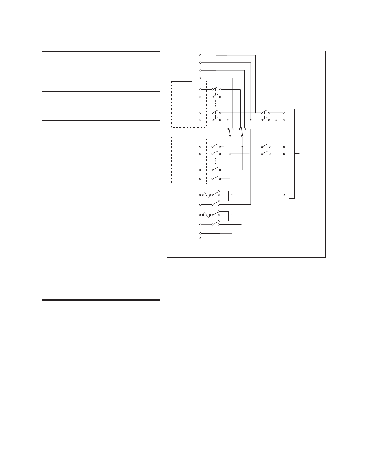
7700
20-Channel Differential Multiplexer w/Automatic CJC
GENERAL
20 CHANNELS: 20 channels of 2-pole relay input. All channels config-
urable to 4-pole.
2 CHANNELS: 2 channels of current only input.
RELAY TYPE: Latching electromechanical.
ACTUATION TIME: <3ms.
CAPABILITIES
CHANNELS 1-20: Multiplex one of 20 2-pole or one of 10 4-pole signals
into DMM.
CHANNELS 21-22: Multiplex one of 2 2-pole current signals into DMM.
INPUTS
MAXIMUM SIGNAL LEVEL:
Channels (1-20): 300V DC or 300V rms (425V peak) for AC waveforms,
1A switched, 60W, 125VA maximum.
Channels (21-22): 60V DC or 30V rms, 3A switched, 60W, 125VA maxi-
mum.
CONTACT LIFE (typ): >10
CONTACT RESISTANCE: <1Ω at end of contact life.
CONTACT POTENTIAL: <±500nV typical per contact, 1μV max.
OFFSET CURRENT: <100pA.
CONNECTOR TYPE: Screw terminal, #20 AWG wire size.
ISOLATION BETWEEN ANY TWO TERMINALS: >10
ISOLATION BETWEEN ANY TERMINAL AND EARTH: >10
CROSS TALK (50Ω Load):
10MHz: <–40dB <-40dB
25MHz: ** <-25dB
* Channels 24 and 25 are open. Refer to ROUTe:MULTiple command
in 27xx User’s manual.
** Not valid
INSERTION LOSS (50Ω Source, 50Ω Load):
<0.1dB 1MHz 1MHz
<3db 2MHz 50MHz
* Channels 24 and 25 are open. Refer to ROUTe:MULTiple command
in 27xx User’s manual.
COMMON MODE VOLTAGE: 300V or 300V rms (425V peak) for AC wave-
forms betw
een any terminal and chassis.
T/C COLD JUNCTION: 1.0°C (18°–28°C Mainframe Temp)
5
operations at max signal level.
8
>10
operations cold switching.
<±500nV typical per contact pair, 1μV max.
10
Ω, <100pF.
w/Internal DMM w/o Internal DMM*
w/Internal DMM w/o Internal DMM*
1.5°C (0°–18°C & 28°–50°C Mainframe Temp).
9
Ω, <200pF.
Card Input
Card Sense
Cold junction
Ref x3
Channel 1
(Channels 2–9)
Channel 10
Cold junction
Ref x3
Channel 11
Channels 12–19)
(
Channel 20
Channel 21
Channel 22
AMPS
Card
HI
LO
HI
LO
HI
LO
HI
LO
HI
LO
HI
LO
H
LO
HI
LO
LO
I
hannel 23
C
-Pole (Open)
2
4-Pole (Closed)
(see Note)
3A
3A
Channel 25
(see Note)
Backplane
isolation
Channel 24
(see Note)
Backplane
isolation
NOTE Channels 23–25 in this schematic
refer to the designations used for
control and not actual available channels.
For more information, refer to the
ROUTe:MULTiple command section
in the Model 2700 User’s Manual.
Channels 24 and 25 can be individually
controlled using ROUTe:MULTiple if the
module is not to be connected to the
internal DMM.
AMPS
HI
Input
LO
HI
Sense
LO
To Model 27xx
Backplane
ENVIRONMENTAL:
OPERATING ENVIRONMENT: Specified for 0°C to 50°C.
STORAGE ENVIRONMENT: –25°C to 65°C.
WEIGHT: 0.45kg (1 lb).
Specified to 80% R.H. at 35°C.
02/02/06
.C
Rev
Page 5
08/01/07
Rev. B
GENERAL
40 CHANNELS: 40 channels of 2-pole relay input.
All channels configurable to 4-pole.
2 CHANNELS: 2 channels of current only input.
RELAY TYPE: Latching electromechanical.
ACTUATION TIME: <3ms.
CAPABILITIES
CHANNELS 1-40: Multiplex one of 40 2-pole or one of 20 4-pole signals
into DMM.
CHANNELS 41-42: Multiplex one of 2 2-pole current signals into DMM.
INPUTS
MAXIMUM SIGNAL LEVEL:
Channels (1-40): 300V DC or rms, 1A switched, 60W, 125VA maximum.
Channels (41-42): 60V DC or 30V rms, 3A switched, 60W, 125VA maxi-
mum.
CONTACT LIFE (typ): >10
5
operations at max signal level.
>108operations no load.
1
CONTACT RESISTANCE: <1 at end of contact life.
CONTACT POTENTIAL: <±500nV typical per contact, 1µV max.
<±500nV typical per contact pair, 1µV max.
OFFSET CURRENT: <100pA.
CONNECTOR TYPE: Screw terminal, #20 AWG wire size.
ISOLATION BETWEEN ANY TWO TERMINALS: >10
10
, <100pF.
ISOLATION BETWEEN ANY TERMINAL AND EARTH: >10
9
, <200pF.
CROSS TALK (10MHz, 50 Load): <–40dB.
INSERTION LOSS (50 Source,50 Load): <0.1dB below 1MHz.
<3dB below 2MHz.
COMMON MODE VOLTAGE: 300V between any terminal and chassis.
ENVIRONMENTAL
OPERATING ENVIRONMENT: Specified for 0°C to 50°C.
Specified to 80% R.H. at 35°C.
STORAGE ENVIRONMENT: –25°C to 65°C.
WEIGHT: 0.5kg (1.1 lb).
Specifications subject to change without notice.
1. Minimum signal level 10mV, 10uA.
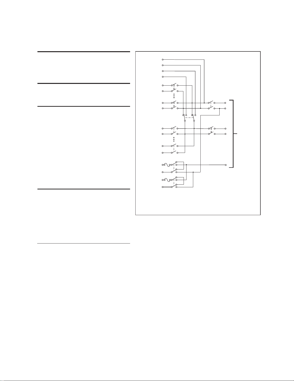
7702 40-Channel Differential Multiplexer
HI
Card Input
LO
HI
Card Sense
LO
HI
Channel 1
LO
(Channels 2–19)
HI
Channel 20
LO
HI
Channel 21
LO
(Channels 22–39)
HI
Channel 40
LO
HI
Channel 41
LO
HI
Channel 42
LO
Channel 43
2-Pole (Open)
4-Pole (Closed)
(see Note)
3A
3A
Channel 45
(see Note)
Backplane
isolation
Channel 44
(see Note)
Backplane
isolation
NOTE Channels 43–45 in this schematic
refer to the designations used for
control and not actual available channels.
For more information, refer to the
ROUTe:MULTiple command section
in the Model 27
Channels 44 and 45 can be individually
controlled using ROUT
module is not to be connected to the
internal DMM.
HI
Input
LO
HI
Sense
LO
AMPS
xx User’s Manual.
To Model 27
Backplane
e:MULTiple if the
xx
Page 6
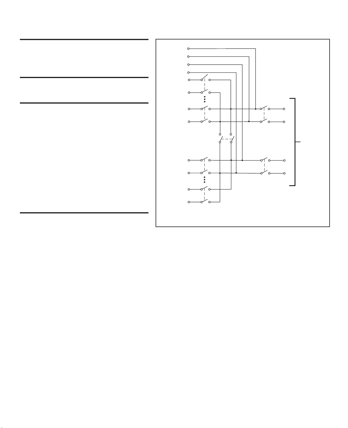
7703 32-Channel High Speed Differential Multiplexer
GENERAL
32 CHANNELS: 32 channels of 2-pole relay input.
RELAY TYPE: Reed.
ACTUATION TIME: <1ms.
All channels configurable to 4-pole.
CAPABILITIES
CHANNELS 1-32: Multiplex one of 32 2-pole or one of 16 4-pole signals
into DMM.
INPUTS
MAXIMUM SIGNAL LEVEL:
Channels (1-32): 300V DC or rms, 0.5A switched, 10W maximum.
4
Contact Life (typ): >5×10
operations at max signal level.
>108operations cold switching.
CONTACT RESISTANCE: <1Ω at end of contact life.
CONTACT POTENTIAL: <±3µV typical per contact, 6µV max.
<±3µV typical per contact pair, 6µV max.
OFFSET CURRENT: <100pA.
CONNECTOR TYPE: 50 pin D-sub × 2.
RELAY DRIVE CURRENT: 20mA per channel.
9
ISOLATION BETWEEN ANY TWO TERMINALS: >10
ISOLATION BETWEEN ANY TERMINAL AND EARTH: >10
Ω, <200pF.
9
Ω, <400pF.
CROSS TALK (1 MHz, 50Ω Load): <–40dB.
INSERTION LOSS (50ΩSource, 50ΩLoad): <0.35dB below 1MHz.
<3dB below 2MHz.
COMMON MODE VOLTAGE: 300V between any terminal and chassis.
ENVIRONMENTAL
OPERATING ENVIRONMENT:Specified for 0°C to 50°C.
STORAGE ENVIRONMENT: –25°C to 65°C.
WEIGHT: 0.8kg (1.75 lbs).
Specified to 40% R.H. at 35°C.
HI
Card Input
LO
HI
Card Sense
LO
HI
Channel 1
LO
(Channels 2–15)
HI
Channel 16
LO
HI
Channel 17
LO
(Channels 18–31)
HI
Channel 32
LO
Channel 35
2-Pole (Closed)
4-Pole (Open)
(see Note)
Channel 33
(see Note)
Backplane
isolation
Channel 34
(see Note)
Backplane
isolation
NOTE Channels 33–35 in this schematic
refer to the designations used for
control and not actual available channels.
For more information, refer to the
ROUTE:MULT command section
in the Model 27xx User’s Manual.
HI
Input
LO
HI
Sense
LO
To Model 27xx
Backplane
Rev. A
Page 7

This page intentionally left blank.
Page 8

Keithley Instruments, Inc.
28775 Aurora Road
Cleveland, Ohio 44139
(440) 248-0400
Fax: (440) 248-6168
www.keithley.com
Model 7700, 7702, and 7703 Multiplexer Modules
User’s Guide
Introduction
t^okfkd Connection and wiring procedures contained in this User’s Guide are intended for use
by qualified service personnel only. Do not perform these procedures unless qualified to
do so. Failure to recognize and observe normal safety precautions could result in
personal injury or death.
This document contains information specific to the Models 7700, 7702, and 7703 multiplexer modules. These modules can be
used in the following Model 27xx DMM mainframes:
• 7700 Module – This module can be used in Model 2700, 2701, and 2750 mainframes.
• 7702 Module – This module can be used in Model 2700, 2701, 2750, and 2790 mainframes.
• 7703 Module – This module can be used in Model 2700, 2701, and 2750 mainframes.
All references to the Model 27xx apply to the Models 2700, 2701, and 2750.
If you have any questions after reviewing this information, please contact your local Keithley representative or call our
Applications Engineers at 1-888-KEITHLEY (1-888-534-8453, U.S. only) or Telefax: 440-498-2990 (Instrument Products).
t^okfkd Before operating the Model 27xx with an accessory card, verify that the card is properly
installed and the mounting screws are tightly fastened. If the mounting screws are not
properly connected, an electrical shock hazard may be present.
Operation
Model 7700 Operation of the Model 7700 module is covered in Section 2 of the Models 2700, 2701, and 2750 User’s
Manuals.
Model 7702 Except for the number of available switching channels and channel number designations, operation of the
Model 7702 is the same as operation for the Model 7700. Model 7700 operation is covered in Section 2 of the
Models 2700, 2701, and 2750 User’s Manuals. Model 7702 operation is also covered in Section 2 of the
Model
2790 Reference Manual and Section 3 of the Model 2790 User’s Manual. Channel number designations
for the Model 7702 is provided in the schematic provided at the beginning of this user’s guide.
Model 7703 This module is also similar to the Model 7700. Differences include the number of available channels and the
Model 7703 does support amps measurements. Model 7700 operation is covered in Section 2 of the
Models
at the end of this User’s Guide.
2700, 2701, and 2750 User’s Manuals. Channel number designations for the Model 7703 are provided
PA-695 Rev. D / October 2006
Page 9
Amps measurements – The 7703 module does not support amps measurements. System channel operation
cannot be used to close channels while an amps function (DCI or ICI) is selected. See the Model 27xx Manual
for details.
• If an amps function (DCI or ACI) is selected and you attempt to close a system channel, the message
“NO AMPS CHAN” will be displayed briefly. For remote programming, error -222 (Parameter data
out of range) is generated.
• If a system channel is already closed and you attempt to select the DCI or ACI function, the message
“INVALID FUNC” will be displayed briefly. For remote programming, error -221 (Settings conflict)
is generated.
Making amps measurements – In order to perform amps measurements, you must use the front panel inputs
of the 27xx mainframe. You can still use the 7703 module for other aspects of the test (such as controlling a
bias supply for DUT), but you must use multiple channel operation to close channels.
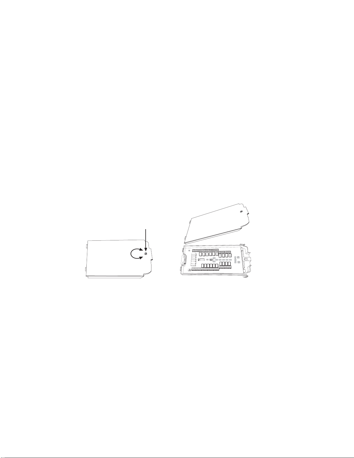
Screw terminal access (Model 7700 and 7702)
Turn the access screw to unlock and open the cover. Press in the access screw to lock.
Figure 1
Screw terminal access
LOCK
K
C
O
L
N
U
INPUT SENSE
H L H L
H L
H L
CH21
CH22
CH6
CH5
CH4
CH3
CH2
CH1
H L
H L
H L
H L
H L
H L
H L
CH11
AMPS
LO
CH7
CH8
H L
H L
H L
H L
CH17
H L
CH12
CH18
H L
H L
H L
H L
CH13
CH14
CH15
CH16
Model 7700 – connections and wiring
The Model 7700 is a 20-channel differential multiplexer module with the following features:
• 2-wire or 4-wire ¾ measurement (automatically pairs switches for four wire measurements — n + 10)
• Screw terminal connections
• Temperature applications (RTD, thermistor, thermocouple)
• Two protected channels for current measurements (external shunts not required)
• Built-in cold junction reference
• Latching type relays (relays hold their position after power is removed)
• Designed specifically for use with Keithley’s Models 2700, 2701, and 2750 Systems.
CH9
CH10
H L
H L
INPUT
(V,2 WIRE)
SENSE
(OHMS, 4 WIRE)
H L
H L
CH19
CH20
2
Page 10

Connection information
t^okfkd The information in this section is intended for qualified service personnel. Do not
attempt to perform this procedure unless qualified to do so.
Do not exceed the maximum specifications for the Model 7700.
Connections to DMM functions are provided through the card backplane connector.
• Current provided for through two protected channels (Channels 21 and 22).
• INPUT connections.
•SENSE (¾4 Wire) connections.
• AMP and LO common connections to the DMM are also provided.
Figure 2
Model 7700 screw terminal channel designations
H L
CH21
INPUT
H L
H L
CH22
SENSE
H L
AMPS
LO
CH1
H L
H L
CH21
H L
CH11
INPUT SENSE
H L H L
H L
CH22
H L
CH12
CH2
H L
AMPS
CH1
H L
LO
H L
CH11
CH3
H L
CH2
H L
H L
CH12
H L
CH13
CH3
H L
H L
CH13
CH4
H L
CH4
H L
H L
CH14
H L
CH14
CH5
H L
H L
CH15
CH5
H L
CH6
H L
H L
CH16
H L
CH15
CH7
H L
H L
CH17
CH6
H L
CH8
H L
H L
CH18
H L
CH16
CH9
H L
H L
CH19
CH7
H L
CH10
H L
H L
CH20
CH8
CH9
H L
H L
INPUT
(V,2 WIRE)
SENSE
(OHMS, 4 WIRE)
H L
CH17
H L
CH18
CH10
H L
Cable tie holes
H L
CH19
Cable tie holes
H L
CH20
3
Page 11
Wiring procedure
INPUT
H L
CH1
H L
CH2
H L
CH3
H L
CH4
H L
C
H
t^okfkd The information in this section is intended for qualified service personnel. Do not
attempt to perform this procedure unless qualified to do so.
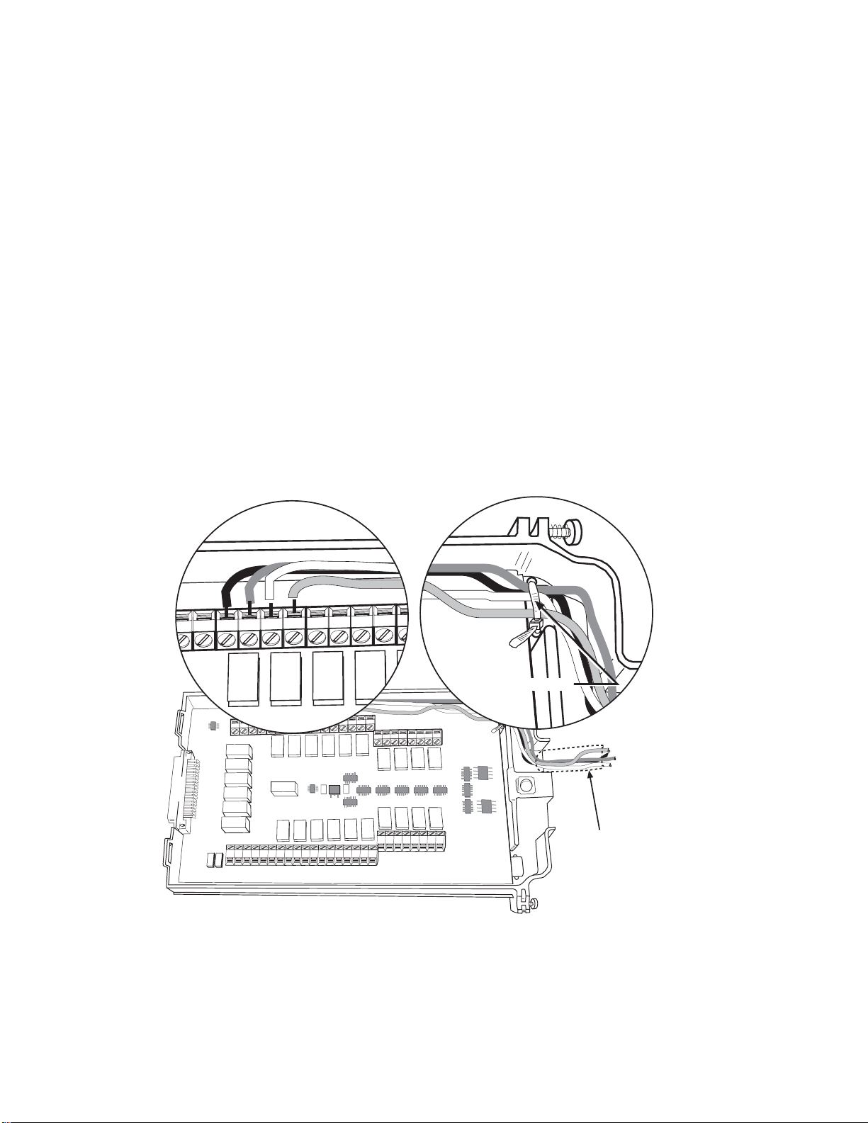
Use the following procedure to wire the Model 7700 module. Make all connections using correct wire size (up to 20 AWG).
Also, make sure to add supplementary insulation around the harness for voltages above 42V peak (see Figure 3).
t^okfkd All wiring must be rated for the maximum voltage in the system. For example, if 1000V
is applied to the front terminals of the Models 2700, 2701, or 2750, the plug-in module
wiring must be rated for 1000V.
1. Make sure all power is discharged from the Model 7700 module.
2. Access the screw terminals (see “Screw terminal access” located at the front of this document).
3. Using a small flat-blade screwdriver, loosen terminal screws and install wires as desired. (Figure 3 shows connections to
channels 1 and 2).
4. Route wire along wire-path and secure with cable tie as shown.
5. Fill in a copy of the connection log and affix it to the module cover.
6. Close and lock the cover.
Figure 3
Wire dressing — Model 7700
Cable tie
INPUT SENSE
H L H L
H L
CH21
H L
CH22
AMPS
H L
H L
H L
H L
H L
H L
CH11
CH12
CH13
LO
H L
CH14
H L
H L
H L
CH15
H L
H L
CH16
CH7
H L
H L
CH17
CH8
H L
H L
CH18
CH9
H L
H L
CH19
CH10
H L
H L
CH20
INPUT
(V,2 WIRE)
SENSE
(OHMS, 4 WIRE)
Supplementary
Insulation
CH6
CH5
CH4
CH3
CH2
CH1
Connection log
Make a copy of Table 1 and affix it to the cover of the Model 7700. Use this to record connection information and channel
descriptions as needed.
4
Page 12

Tab l e 1
Connection log Model 7700
Channel Color Description
AMPS COM
INPUT
SENSE
CH1
CH2
CH3
CH4
CH5
CH6
CH7
CH8
CH9
CH10
CH11
CH12
CH13
CH14
CH15
CH16
CH17
CH18
CH19
CH20
AMPS21
AMPS22
H
L
H
L
H
L
H
L
H
L
H
L
H
L
H
L
H
L
H
L
H
L
H
L
H
L
H
L
H
L
H
L
H
L
H
L
H
L
H
L
H
L
H
L
H
L
H
L
H
L
5
Page 13

Model 7702 – connections and wiring
The Model 7702 is a 40-channel differential multiplexer module with the following features:
• 2-wire or 4-wire ¾ measurement (automatically pairs switches for four wire measurements — n + 20)
• Two protected channels for current measurements (external shunts not required)
• Temperature applications (RTD, thermistor, thermocouple)
• Latching type relays (relays hold their position after power is removed)
• Screw terminal connections
• Designed specifically for use with Keithley’s Models 2700, 2701, 2750 or 2790 Systems.
Connection information
t^okfkd The information in this section is intended for qualified service personnel. Do not
attempt to perform this procedure unless qualified to do so.
Do not exceed the maximum specifications for the Model 7702.
Connections to DMM functions are provided through the card backplane connector.
• Current provided for through two protected channels (Channels 41 and 42).
• INPUT connections.
•SENSE (¾4 Wire) connections.
• AMP and LO common connections to the DMM are also provided.
Wiring procedure
t^okfkd The information in this section is intended for qualified service personnel. Do not
attempt to perform this procedure unless qualified to do so.
Use the following procedure to wire the Model 7702 module. Make all connections using correct wire size (up to 20 AWG).
Also, make sure to add supplementary insulation around the harness for voltages above 42V peak (see Figure 5).
t^okfkd All wiring must be rated for the maximum voltage in the system. For example, if 1000V
is applied to the front terminals of the Models 2700, 2701, 2750, or 2790, the plug-in
module wiring must be rated for 1000V.
1. Make sure all power is discharged from the Model 7702 module.
2. Access the screw terminals (see “Screw terminal access” located at the front of this document).
3. Using a small flat-blade screwdriver, loosen terminal screws and install wires as desired. (Figure 5 shows connections to
the Input and Sense).
4. Route wire along wire-path and secure with cable ties as shown.
5. Fill in a copy of the connection log and affix it to the module cover.
6. Close and lock the cover.
6
Page 14

Figure 4
TE122
TE121
Model 7702 Screw terminal channel designations
CH2
H L
CH1
H L
CH3
H L
CH4
H L
CH5
H L
CH6
H L
CH7
H L
CH8
H L
CH9
H L
TE122
TE121
CH10
H L
CH11
H L
CH12
H L
CH13
H L
CH14
H L
CH15
H L
CH16
H L
CH17
H L
CH18
H L
CH19
H L
CH20
H L
H L
CH21
H L
CH22
H L
CH23
H L
CH24
H L
CH25
H L
CH26
CH27
INPUT
H L
H L
H L
CH28
H L
CH29
H L
CH41
H L
CH30
H L
CH31
H L
CH32
H L
CH42
H L
CH33
H L
CH34
SENSE
H L
H L
CH35
H L
CH36
H L
CH37
H L
CH38
H L
CH40
H L
CH39
7
Page 15
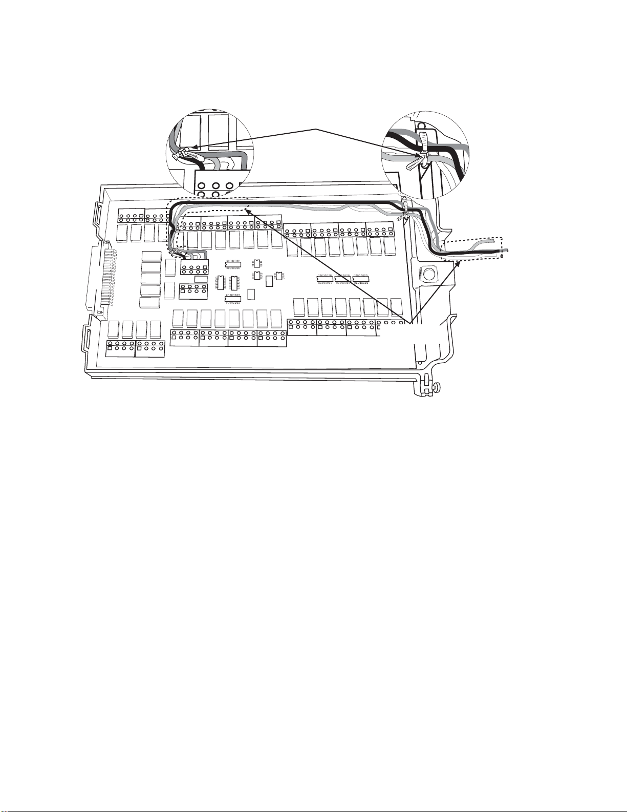
Figure 5
T
Wire dressing — Model 7702
Cable tie
(2 places)
TE122
TE121
Supplementary
Insulation
Connection log
Make a copy of Table 2 and affix it to the cover of the Model 7702. Use this to record connection information and channel
descriptions as needed.
8
Page 16

Tab l e 2
Connection log Model 7702
Channel Color Description Description Color Channel
INPUT
SENSE
CH21
CH22
CH23
CH24
CH25
CH26
CH27
CH28
CH29
CH30
CH31
CH32
CH33
CH34
CH35
CH36
CH37
CH38
CH39
CH40
AMPS41
H
L
H
L
H H
L L
H H
L L
H H
L L
H H
L L
H H
L L
H H
L L
H H
L L
H H
L L
H H
L L
H H
L L
H H
L L
H H
L L
H H
L L
H H
L L
H H
L L
H H
L L
H H
L L
H H
L L
H H
L L
H H
L L
H H
L L
CH1
CH2
CH3
CH4
CH5
CH6
CH7
CH8
CH9
CH10
CH11
CH12
CH13
CH14
CH15
CH16
CH17
CH18
CH19
CH20
AMPS42
9
Page 17
Model 7703 – connections and wiring
The Model 7703 is a 32-channel high speed differential multiplexer module with the following features:
• 2-wire or 4-wire ¾ measurement (automatically pairs switches for four wire measurements — n + 16)
• 50-pin D-Shell connectors (2 × DB50)
• Temperature applications (RTD or thermistor)
• High-speed non-latching reed relays (relays go to open state after power is removed or *RST)
• Designed specifically for use with Keithley’s Models 2700, 2701, and 2750 Systems.
klqb The 50-pin D-Shell connector mates with Model 7788.
Card configuration—connections
t^okfkd The information in this section is intended for qualified service personnel. Do not
attempt to perform this procedure unless qualified to do so.
Do not exceed the maximum specifications for the Model 7703 module.
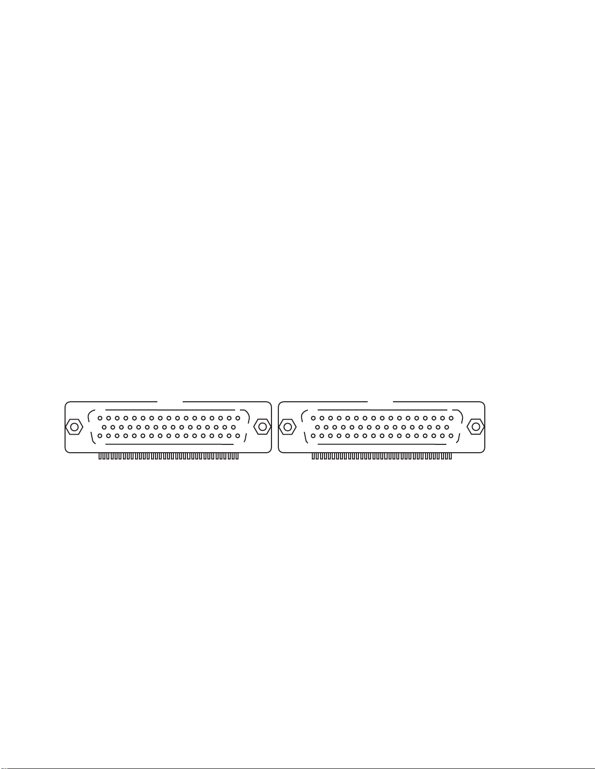
klqb When looking at the rear connectors of the Model 7703 module, the connector on the left is P1017
and the connector on the right is P1016.
Figure 6
Rear view—Model 7703 Pinouts (P1016 and P1017)
P1016
1
18
34
33
17
50
P1017
1
34
18
17
33
50
Make all connections using correct wire size (up to 20 AWG). Also, make sure to add supplementary insulation around the
harness for voltages above 42V peak (see Figure 7).
t^okfkd All wiring must be rated for the maximum voltage in the system. For example, if 1000V
is applied to the front terminals of the Models 2700, 2701, or 2750, the plug-in module
wiring must be rated for 1000V.
Make all connections using correct wire size (up to 20 AWG) (refer to the Model 7788 documentation for specific wiring
instructions).
10
Page 18
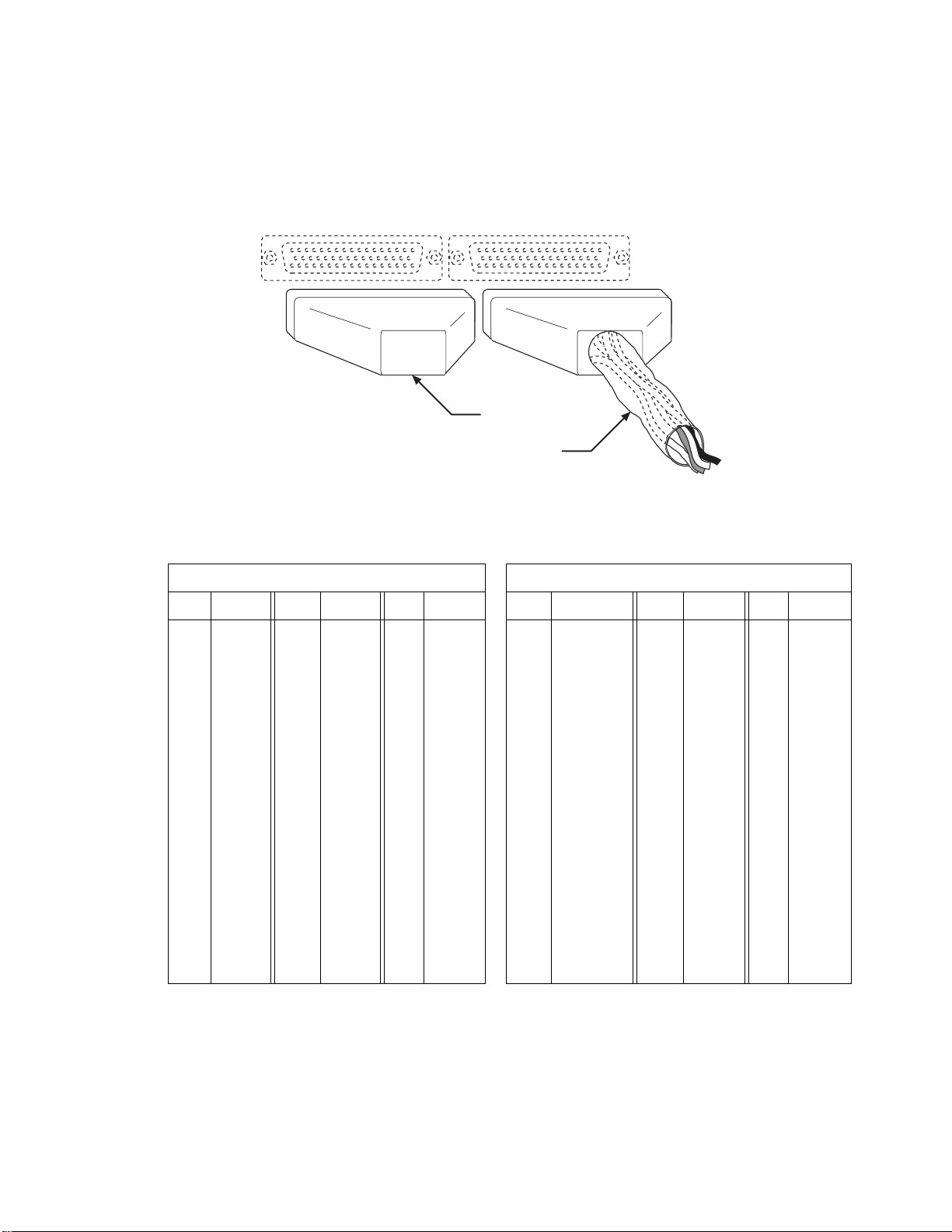
`^rqflk If both connectors (P1017 and P1016) are not used, install the extra Model 7788 50-pin
D-shell as a plug on the open connector (see Figure 7
electrical shock hazard may be present.
Figure 7
Supplementary insulation and plugging an unused connector
Install plug (unused
Model 7788) in
unused connector
Supplementary
Insulation
Table 3
Model 7703 channel designations
). If the connector is left open, an
P1017 P1016
Pin CH Pin CH Pin CH Pin CH Pin CH Pin CH
18 9 HI 30 15 HI 42 29 HI 1 Sense HI 26 5 HI 38 19 HI
19 9 LO 31 15 LO 43 29 LO 2 Sense LO 27 5 LO 39 19 LO
20 10 HI 32 16 HI 44 30 HI 4 Input HI 28 6 HI 40 20 HI
21 10 LO 33 16 LO 45 30 LO 6 Input LO 29 6 LO 41 20 LO
22 11 HI 34 25 HI 46 31 HI 18 1 HI 30 7 HI 42 21 HI
23 11 LO 35 25 LO 47 31 LO 19 1 LO 31 7 LO 43 21 LO
24 12 HI 36 26 HI 48 32 HI 20 2 HI 32 8 HI 44 22 HI
25 12 LO 37 26 LO 49 32 LO 21 2 LO 33 8 LO 45 22 LO
26 13 HI 38 27 HI 22 3 HI 34 17 HI 46 23 HI
27 13 LO 39 27 LO 23 3 LO 35 17 LO 47 23 LO
28 14 HI 40 28 HI 24 4 HI 36 18 HI 48 24 HI
29 14 LO 41 28 LO 25 4 LO 37 18 LO 49 24 LO
11
Page 19

Connection log
Make a copy of Table 4 and affix it to the cover of the Model 7703. Use this to record connection information and channel
descriptions as needed.
Table 4
Connection log Model 7703
Channel Color Description Description Color Channel
INPUT
SENSE
CH1
CH2
CH3
CH4
CH5
CH6
CH7
CH8
CH9
CH10
CH11
CH12
CH13
CH14
CH15
CH16
H
L
H
L
H H
L L
H H
L L
H H
L L
H H
L L
H H
L L
H H
L L
H H
L L
H H
L L
H H
L L
H H
L L
H H
L L
H H
L L
H H
L L
H H
L L
H H
L L
H H
L L
CH17
CH18
CH19
CH20
CH21
CH22
CH23
CH24
CH25
CH26
CH27
CH28
CH29
CH30
CH31
CH32
12
Page 20

12/04
Specifications are subject to change without notice.
All Keithley trademarks and trade names are the property of Keithley Instruments, Inc.
All other trademarks and trade names are the property of their respective companies.
A GREATER MEASURE OF CONFIDENCE
Keithley Instruments, Inc.
Corporate Headquarters • 28775 Aurora Road • Cleveland, Ohio 44139 • 440-248-0400 • Fax: 440-248-6168 • 1-888-KEITHLEY (534-8453) • www.keithley.com
 Loading...