

Page 1
2015, 2016 6
1
⁄2-Digit THD Multimeters
2015-P 6
• THD, THD+Noise, and SINAD
measurements
• 20Hz–20kHz sine wave
generator
• Fast frequency sweeps
• 2015-P: Identifies peak spectral
components
• 2015: 4Vrms single-ended or
8Vrms differential output
• 2016: 9.5Vrms single-ended or
19Vrms differential output
• Individual harmonic magnitude
measurements
• 5 standard audio shaping filters
1
• 13 DMM functions (6
⁄2 digits)
1
⁄2-Digit Audio Analyzing Multimeter
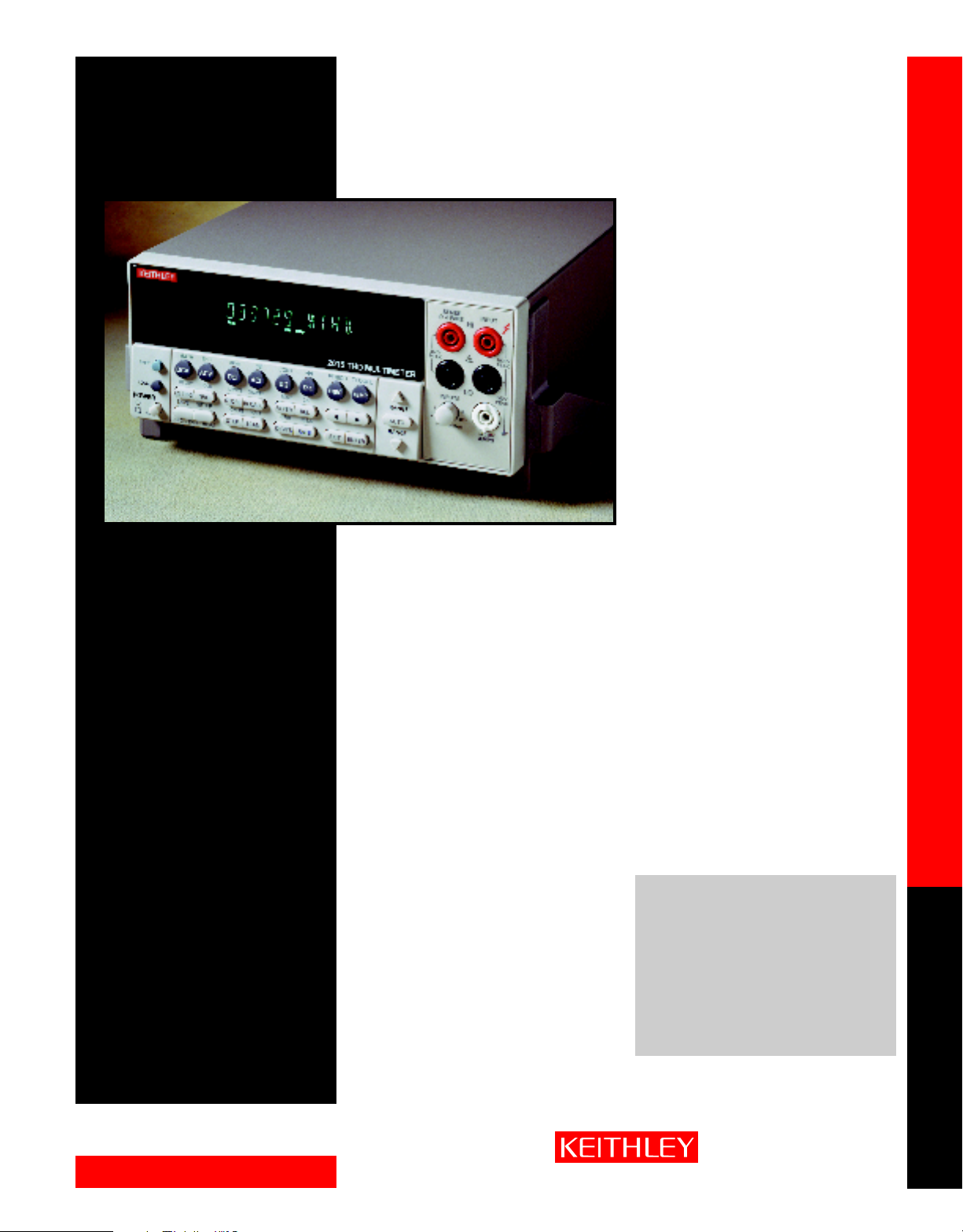
The Model 2015-P Audio Analyzing Digital
Multimeter and the Models 2015 and 2016 Total
Harmonic Distortion Multimeters combine audio
band quality measurements and analysis with a fullfunction 6
broad range of voltage, resistance, current, frequency, and distortion measurements, all with the
same compact, half-rack measurement instrument.
The Model 2016 has twice the sine wave generator
output of the Model 2015 for applications that
require test signals greater than 8Vrms. The Model
2015-P offers additional processing capacity for frequency spectrum analysis.
Frequency Domain Distortion
Analysis
For applications such as assessing non-linear distortion in components, devices, and systems, DSPbased processing allows the Models 2015-P, 2015,
and 2016 to provide frequency domain analysis in
conventional time domain instruments. They can
measure Total Harmonic Distortion (THD) over a
the complete 20Hz to 20kHz audio band. They also measure over a wide input range (up to 750Vrms)
and have low residual distortion (–87dB). The THD reading can be expressed either in decibels or as a
percentage.
In addition to THD, the Models 2015-P, 2015, and 2016 can compute THD+Noise and Signal-to-Noise plus
Distortion (SINAD). For analyses in which the individual harmonics are the criteria of greatest interest,
the instruments can report any of the (up to 64) harmonic magnitudes that can be included in the distortion measurements. The user can program the actual number of harmonics to be included in a computation, so accuracy, speed, and complexity can be optimized for a specific application.
Optimized for Production Testing
The Models 2015-P, 2015, and 2016 can perform fast frequency sweeps for characterizing audio-band circuitry in production test systems. For example, the instruments can execute a single sweep of 30 frequencies and transmit both rms voltage readings and THD readings to a computer in only 1.1 seconds. With
that data, a complete frequency response analysis and a harmonic distortion vs. frequency analysis can be
performed in a very short time. Thus high speed testing of the audio performance of a high volume
device such as a cellular telephone can be performed without reducing the number of tests or reducing
the measurements in each test. With these instruments, which are optimized for production testing, test
engineers can lower test times, in comparison to test speeds achievable with general purpose audio analyzers, without sacrificing production test quality.
Dual Output Source
The Models 2015-P, 2015, and 2016 include an
internal audio band sine wave source for generating stimulus signals. A second output, the inverse
of the first output, is also available, simplifying the
testing of differential input circuits for common
mode or noise cancellation performance.
The Models 2015 and 2015-P have a 4Vrms singleended output and 8Vrms differential source output. For tests that require a higher stimulus signal,
the Model 2016 provides a 9.5Vrms single-ended
output and a 19Vrms differential output.
1
⁄2-digit DMM. Test engineers can make a
APPLICATIONS
• Wireless communication device
audio quality testing
• Component linearity testing
• Lighting and ballast THD limit
conformance testing
• Telephone and automotive
speaker testing
Audio analyzing and Total Harmonic Distortion DMMs
1.888.KEITHLEY (U.S. only)
www.keithley.com
DIGITAL MULTIMETERS
A GREATER MEASURE OF CONFIDENCE
Page 2
2015, 2016 6
1
⁄2-Digit THD Multimeters
2015-P 6
Ordering Information
2015 Total Harmonic
Distortion 6
Multimeter
2015-P Audio Analyzing DMM
2016 Total Harmonic
Distortion 6
DMM w/9V Source
Output
These products are available
with an Extended Warranty.
Accessories Supplied
Model 1751 Safety Test Leads,
User Manual, Service Manual.
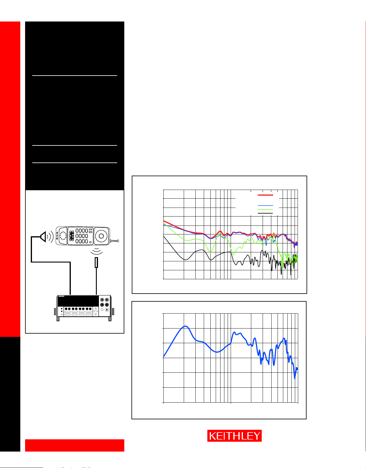
Figure 1. Total Harmonic Distortion
Analysis and Frequency
Response of a Portable Wireless
Telecommunication Device
Output
Transducer
Audio analyzing and Total Harmonic Distortion DMMs
Source
Output
1
⁄2-Digit
1
⁄2-Digit
Device Under Test
Input
Transducer
Signal
Input
⁄2-Digit Audio Analyzing Multimeter
Wide Selection of Audio Filters
Five industry-standard bandpass filters are provided for shaping the input signal for audio and telecommunication applications. Available filters include the CCITT weighting filter, CCIR filter, C-message filter,
CCIR/ARM filter, and “A” weighting filter. The Models 2015-P, 2015, and 2016 provide programmable, high cutoff (low pass) and low cutoff (high pass) filters. Furthermore, the two filters can be implemented together to
form a bandpass filter. The programmable filters can be used to filter out noise generated by electromechanical
machinery on the production floor or to simulate other types of system transmission characteristics.
Broad Measurement Flexibility
In addition to their THD, THD+Noise, SINAD, and individual harmonic measurement capabilities, the
instruments provide a comprehensive set of DMM functions, including DCV, ACV, DCI, ACI, 2WΩ, 4WΩ,
temperature, frequency, period, dB, dBm, and continuity measurements, as well as diode testing. This
multi-functional design minimizes added equipment costs when configuring test setups.
Figure 2. THD and 2nd, 3rd, and 4th Harmonics as a Function of Frequency
0
–10
–20
–30
–40
Relative
Output
Level (dB)
–50
–60
–70
–80
–90
–100
100 1000 10000
1
THD:
Levels relative to fundamental:
2nd harmonic
3rd harmonic
4th harmonic
Frequency, Hz
2015 MULTIMETER
Model 2015
Figures 1, 2, and 3 demonstrate how the Model
2015-P, 2015, or 2016 can provide both time
domain and frequency domain measurements
in a single test protocol. Figure 1 shows a
sample test system schematic with a telecommunication device in a loop back mode test.
The Model 2015 source provides a stimulus
frequency sweep, and the Model 2015 measures the response from the microphone circuit.
Figure 2 shows the resulting frequency domain
analysis of the THD and the first three harmonics as a function of frequency. Figure 3 shows
the time domain analysis of microphone circuit
output voltage as a function of frequency.
1.888.KEITHLEY (U.S. only)
DIGITAL MULTIMETERS
www.keithley.com
Figure 3. Frequency Response
10
5
0
Relative
Output
(dB)
-5
-10
-15
-20
100 1000 10000
A GREATER MEASURE OF CONFIDENCE
Frequency (Hz)
Page 3
2015, 2016 6
1
⁄2-Digit THD Multimeters
2015-P 6
Wide Band or Narrow Band
Noise Measurements
The Models 2015-P, 2015, and 2016 are capable of
measuring both wide band noise and narrow band
noise. Alternatively, these instruments’ DSP (digital
signal processing) capabilities allow users to make
frequency domain measurements of RMS voltage
noise over the 20Hz–20kHz frequency audio band
or a narrow portion of the band. Furthermore,
noise measurements can be extracted in the presence of a stimulus signal for fast signal-to-noise
computations.
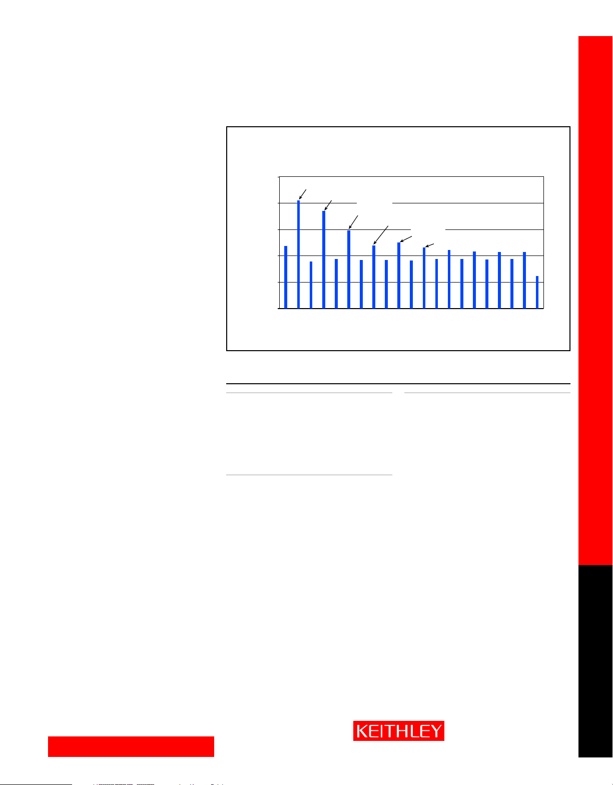
Spectrum Analysis
The Model 2015-P has internal computational
capabilities that allow it to characterize an acquired
signal spectrum. This instrument can identify and
report the frequency and amplitude of the highest
value in a complete spectrum or within a specified
frequency band. It can also identify additional
peaks in descending order of magnitude. The
Model 2015-P’s on-board capabilities make it simple to obtain a thorough analysis of a frequency
spectrum more quickly and with little or no need
for external analysis software.
CABLES/ADAPTERS
7007-1 Shielded IEEE-488 Cable, 1m (3.3 ft)
7007-2 Shielded IEEE-488 Cable, 2m (6.6 ft)
8501-1, Trigger-Link Cables, 1m (3.3 ft),
8501-2 2m (6.6 ft)
8502 Trigger Link Adapter Box
8503 Trigger Link Cable to 2 male BNCs,1m (3.3 ft)
7009-5 RS-232 Cable
RACK MOUNT KITS
4288-1 Single Fixed Rack Mount Kit
4288-2 Dual Fixed Rack Mount Kit
1
⁄2-Digit Audio Analyzing Multimeter
Figure 4. The Model 2015-P directly identifies peak values of the frequency spectrum.
Frequency Spectrum
–20
–40
–60
–80
Magnitude (dBV)
–100
–120
1.0kHz 1.1kHz 1.2kHz 1.3kHz 1.4kHz
Maximum
Between 1.0kHz and 1.4kHz
2nd peak
3rd peak
Maximum left of 4th peak
4th peak
Maximum right of 4th peak
Frequency
ACCESSORIES AVAILABLE
OTHER
KPCI-488 IEEE-488 Interface/Controller for the PCI Bus
KPC-488.2AT IEEE-488 Interface Card for IBM PC/AT (full
slot)
KPC-TM Trigger Master Interface
TestPoint Test Development Software
1050 Padded Carrying Case
2015-EW 1 Year Warranty Extension
2015-P-EW 1 Year Warranty Extension
2016-EW 1 Year Warranty Extension
Audio analyzing and Total Harmonic Distortion DMMs
1.888.KEITHLEY (U.S. only)
www.keithley.com
DIGITAL MULTIMETERS
A GREATER MEASURE OF CONFIDENCE
Page 4

2015, 2016 6
1
⁄2-Digit THD Multimeters
2015-P 6
1
DISTORTION CHARACTERISTICS
VOLTAGE RANGE: 100mV, 1V, 10V, 100V, 750V (user selectable).
INPUT IMPEDANCE: 1MΩ paralleled by <100pF.
DISPLAY RANGE: 0–100% or 0–100.00dB.
RESOLUTION: 0.0001% or 0.00001dB.
FUNDAMENTAL FREQUENCY RANGE: 20Hz–20kHz.
HARMONIC FREQUENCY RANGE: 40Hz–50kHz.
FREQUENCY RESOLUTION: 0.008Hz.
FREQUENCY ACCURACY: ±0.01% of reading.
FREQUENCY TEMPERATURE COEFFICIENT: ≤ 100ppm over operating temperature range.
MEASUREMENT ACCURAC Y RESIDUAL
MODE (1 Year, 23°C ±5°C) DISTORTION
THD and individual ±0.8dB, 0.004% or –87dB
harmonic magnitudes 20Hz to 20kHz
THD + n ±1.5 dB, 0.056% or –65dB
SINAD ±1.5dB +65dB
AC Level ±(0.13% of reading +
V rms 0.009% of range)
100Hz to 20kHz
100Hz to 20kHz
20Hz to 20kHz
DISTORTION MEASUREMENT AUDIO FILTERS
None C-Message
CCITT Weighting CCIR/ARM
CCIR “A” Weighting
NUMBER OF HARMONICS INCLUDED IN THD CALCULATION: 2 to 64 (user selectable).
Model 2015, 2015-P, 2016 Specifications
HI AND LO CUTOFF FILTERS (bus settable): 20Hz–50kHz. Can be combined to form brick-
wall bandpass filter.
DISTORTION MEASUREMENT READING RATE
FUNDAMENTAL MINIMUM
FREQUENCY FUNDAMENTAL READINGS
ACQUISITION FREQUENCY PER
MODE RANGE SECOND
Single acquisition 20 Hz to 100 Hz 14
or stored value 100 Hz to 1 kHz 24
Automatic 20 Hz to 30 Hz 5.5
1 kHz to 20 kHz 28
30 Hz to 400 Hz 6
400 Hz to 20 kHz 6.6
FREQUENCY SWEEP READING RATE
NUMBER OF FREQUENCIES TIME (seconds)
5 0.2
30 1.1
100 3.5
200 6.9
2
2
2
20Hz to 20kHz
20Hz to 20kHz
20Hz to 20kHz
3
⁄2-Digit Audio Analyzing Multimeter
GENERATOR CHARACTERISTICS
FREQUENCY RANGE: 10–20kHz.
FREQUENCY RESOLUTION: 0.007Hz.
FREQUENCY ACCURACY: ±(0.015% of reading + 0.007Hz)1.
FREQUENCY TEMPERATURE COEFFICIENT: <100ppm over operating temperature range.
SOURCE OUTPUT:
WAVEFORM: Sinewave.
AMPLITUDE RANGE: 2015-P, 2015: 2V rms (50Ω and 600Ω) or 4V rms (HI Z).
1
AMPLITUDE RESOLUTION: 2015-P, 2015: 0.5mV rms (50Ω and 600Ω) or 1mV rms (HI Z).
AMPLITUDE ACCURACY: 2015-P, 2015: ±(0.3% of setting + 2mV)
AMPLITUDE TEMPERATURE COEFFICIENT: Typically 0.015%/°C.
AMPLITUDE FLATNESS: ±0.1dB
OUTPUT IMPEDANCE: 50Ω ±1Ω or 600Ω ±10Ω, user selectable.
THD: –64dB
NOISE: 2015-P, 2015: 100µV rms2.
DC OFFSET VOLTAGE: 2015-P, 2015: ±1.2mV
6
.
INV/PULSE OUTPUT (SINEWAVE MODE):
FREQUENCY: Same as source output.
AMPLITUDE RANGE: 2015-P, 2015: 2V rms (50Ω and 600Ω) or 4V rms (HI Z).
AMPLITUDE RESOLUTION: 2015-P, 2015: 0.5mV rms (50Ω and 600Ω) or 1mV rms (HI Z).
AMPLITUDE ACCURACY: 2015-P, 2015: ±(2.0% of setting + 2mV)
AMPLITUDE FLATNESS: ±0.1dB
OUTPUT IMPEDANCE: Same as Source Output setting.
THD: –64dB
NOISE: 2015-P, 2015: 100µV rms
DC OFFSET VOLTAGE: 2015-P, 2015: ±1.1mV typ., ±13mV max.
6
.
INV/PULSE OUTPUT (PULSE MODE):
FREQUENCY: Same as source output.
DUTY CYCLE: 45% ±3%.
OUTPUT IMPEDANCE: Same output impedance as the source output.
4
AMPLITUDE: 0.0V ±0.07V to 4.9V ±0.12V pulse open circuit
OVERSHOOT: 1.0V maximum pulse open circuit
UNDERSHOOT: 1.1V maximum pulse open circuit
0.0V ±0.05V to 3.3V ±0.08V pulse 100Ω load
0.2V maximum with 100Ω load pulse open circuit
0.45V maximum with 100Ω load pulse open circuit
2016: 2V rms (50Ω and 600Ω) or 9.5V rms (HI Z).
2016: 1.25mV rms (50Ω and 600Ω) or 2.5mV rms (HI Z).
2016: ±(0.3% of setting + 5mV)
1, 4, 5
.
2
.
.
1
. 2016: ±3mV1.
2
.
2
.
3
.
3
.
2016: 250µV rms
2016: 2V rms (50Ω and 600Ω) or 9.5V rms (HI Z).
2016: 1.25mV rms (50Ω and 600Ω) or 2.5mV rms (HI Z).
2016: ±(2.0% of setting + 5mV)
1, 4, 5
2016: 250µV rms
2016: ±3mV typ., ±13mV max.
1, 4
.
1, 4
.
1, 4
.
1, 4
.
1
1
1, 3
.
1, 3
.
3
.
3
.
NOTES
1. Input signal at full scale.
2. V
≥20% of range and harmonics >–65dB.
IN
3. Speeds are for default operating conditions (*RST), and display off, auto range off, binary data transfer,
trig delay = 0.
4. Typical times: frequencies in 400–4kHz range, binary data transfer, TRIG DELAY = 0, Display OFF, Auto Range
OFF. Data returned is THDmeasurement plus AC voltage.
1.888.KEITHLEY (U.S. only)
DIGITAL MULTIMETERS
www.keithley.com
NOTES
1. 1 year, 23°C ±5°C.
2. Measured at V
HI Z output impedance, and no load.
3. With HI Z output impedance and 1m 50Ω coaxial cable.
4. HI Z output impedance, no load.
5. 4V output.
6. THD measurement includes harmonics 2 through 5, 1V rms output, HI Z, no load.
A GREATER MEASURE OF CONFIDENCE
= 0V with gain 100 amplifier and 2-pole 50kHz low pass filter, Inv/Pulse in sinewave mode,
OUT
Page 5

2015, 2016 6
1
⁄2-Digit THD Multimeters
2015-P 6
DC Characteristics
CONDITIONS: MED (1 PLC)1 OR SLOW (10 PLC) ACCURACY: ±(PPM OF READING + PPM OF RANGE)
FUNCTION RANGE RESOLUTION VOLTAGE RESISTANCE 23°C ± 1° 23°C ± 5° 23°C ± 5° 0°–18°C & 28°–50°C
VOLTAGE 100.0000 mV 0.1 µV > 10 GΩ 30 + 30 40 + 35 50 + 35 2 + 6
RESISTANCE15100.0000 Ω 100 µΩ 1 mA 30 + 30 80 + 40 100 + 40 8 + 6
CURRENT 10.00000 mA 10 nA < 0.15 V 60 + 15 300 + 40 500 + 40 50 + 5
CONTINUITY 2W 1 kΩ 100 mΩ 1 mA 40 + 100 100 + 100 120 + 100 8 + 1
DIODE TEST 3.00000 V 10 µV 1 mA 20 + 6 30 + 7 40 + 7 8 + 1
OR MED (1 PLC) WITH FILTER OF 10 (PPM = PARTS PER MILLION) (E.G., 10PPM = 0.001%)
TEST CURRENT TEMPERATURE
OR BURDEN INPUT 24 HOUR
1.000000 V 1.0 µV > 10 GΩ 15 + 6 25 + 7 30 + 7 2 + 1
10.00000 V 10 µV > 10 GΩ 15 + 4 20 + 5 30 + 5 2 + 1
100.0000 V 100 µV 10 MΩ ±1% 15 + 6 30 + 6 45 + 6 5 + 1
1000.000 V
1.000000 kΩ 1mΩ 1 mA 20 + 6 80 + 10 100 + 10 8 + 1
10.00000 kΩ 10 mΩ 100 µA 20 + 6 80 + 10 100 + 10 8 + 1
100.0000 kΩ 100 mΩ 10 µA 20 + 6 80 + 10 100 + 10 8 + 1
1.000000 MΩ 1 Ω 10 µA 20 + 6 80 + 10 100 + 10 8 + 1
10.00000 MΩ
100.0000 MΩ
100.0000 mA 100 nA < 0.03 V 100 + 150 300 + 400 500 + 400 50 + 50
1.000000 A 1 µA < 0.3 V 200 + 15 500 + 40 800 + 40 50 + 5
3.00000 A 10 µA < 1 V 1000 + 10 1200 + 15 1200 + 15 50 + 5
10.00000 V 10 µV 100 µA 20 + 6 30 + 7 40 + 7 8 + 1
10.00000 V 10 µV 10 µA 20 + 6 30 + 7 40 + 7 8 + 1
9
1 mV 10 MΩ ±1% 20 + 6 35 + 6 45 + 6 5 + 1
11
10 Ω 700 nA // 10MΩ 150 + 6 200 + 10 400 + 10 25 + 1
11
100 Ω 700 nA // 10MΩ 800 + 30 1500 + 30 1500 + 30 150 + 1
⁄2-Digit Audio Analyzing Multimeter
14
90 DAY 1 YEAR COEFFICIENT
1
DC OPERATING CHARACTERISTICS
FUNCTION DIGITS READINGS/s PLCs
DCV (all ranges), 61⁄
DCI (all ranges), and 6
2W Ohms (<10M range) 61⁄2
DC SYSTEM SPEEDS
RANGE CHANGE3: 50 / s.
FUNCTION CHANGE
AUTORANGE TIME
ASCII READINGS TO RS-232 (19.2K BAUD): 55 / s.
MAX. INTERNAL TRIGGER RATE: 2000 / s.
MAX. EXTERNAL TRIGGER RATE: 400 / s.
3
: 45 / s.
3, 10
: <30 ms.
2, 6
3, 4
2
1
3, 7
⁄2
3, 5
1
3, 5
5
⁄2
5
51⁄2
1
5
5
⁄2
1
5
4
⁄
2
2
8
510
30 1
50 1
270 0.1
500 0.1
1000 0.04
2000 0.01
DC GENERAL
LINEARITY OF 10VDC RANGE: ±(2ppm of reading + 1ppm of range).
DCV, Ω, TEMPERATURE, CONTINUITY, DIODE TEST INPUT PROTECTION: 1000V, all ranges.
MAXIMUM 4WΩ LEAD RESISTANCE: 10% of range per lead for 100Ω and 1kΩ ranges; 1kΩ per
lead for all other ranges.
DC CURRENT INPUT PROTECTION: 3A, 250V fuse.
SHUNT RESISTOR: 0.1Ω for 3A, 1A and 100mA ranges. 10Ω for 10mA range.
CONTINUITY THRESHOLD: Adjustable 1Ω to 1000Ω.
AUTOZERO OFF ERROR: Add ±(2ppm of range error + 5µV) for <10 minutes and ±1°C change.
OVERRANGE: 120% of range except on 1000V, 3A and Diode.
SPEED AND NOISE REJECTION
RATE READINGS/S DIGITS 10V RANGE NMRR
10 PLC 5 61⁄2 < 1.5 µV 60 dB 140 dB
1 PLC 50 6
0.1 PLC 500 51⁄2 < 22 µV — 80 dB
0.01 PLC 2000 41⁄2 < 150 µV — 80 dB
1
⁄2 < 4 µV 60 dB 140 dB
RMS NOISE
12
CMRR
DC NOTES
1. Add the following to ppm of range accuracy specification based on range:1V and 100V, 2ppm; 100mV, 15ppm;
100Ω, 15ppm; <1MΩ, 2ppm; 10mA and 1A, 2ppm; 100mA, 20ppm.
2. Speeds are for 60 Hz operation using factor y default operating conditions (*RST). Autorange off, Display off,
Trigger delay = 0.
3. Speeds include measurement and binar y data transfer out the GPIB.
4. Auto zero off.
5. Sample count = 1024, auto zero off.
6. Auto zero off, NPLC = 0.01.
7. Ohms = 24 readings/second.
8. 1 PLC = 16.67ms @ 60Hz, 20ms @ 50Hz/400Hz. The frequency is automatically determined at power up.
9. For signal levels >500V, add 0.02ppm/V uncertainty for the portion exceeding 500V.
10. Add 120ms for ohms.
11. Must have 10% matching of lead resistance in Input HI and LO.
12. For line frequency ±0.1%.
13. For 1kΩ unbalance in LO lead.
14. Relative to calibration accuracy.
15. Specifications are for 4-wire ohms or 2-wire ohms with REL function.
Model 2015, 2015-P, 2016 Specifications
13
1.888.KEITHLEY (U.S. only)
www.keithley.com
DIGITAL MULTIMETERS
A GREATER MEASURE OF CONFIDENCE
Page 6

2015, 2016 6
1
⁄2-Digit THD Multimeters
2015-P 6
True RMS AC Voltage and Current Characteristics
VOLTAGE CALIBRATION 3 Hz– 10 Hz– 20 kHz– 50 kHz– 100 kHz–
RANGE RESOLUTION CYCLE 10 Hz 20 kHz 50 kHz 100 kHz 300 kHz
100.0000 mV 0.1 µV
1.000000 V 1.0 µV 90 Days 0.35 + 0.03 0.05 + 0.03 0.11 + 0.05 0.60 + 0.08 4 + 0.5
10.00000 V 10 µV
100.0000 V 100 µV 1 Year 0.35 + 0.03 0.06 + 0.03 0.12 + 0.05 0.60 + 0.08 4 + 0.5
750.000 V 1 mV
TEMPERATURE
COEFFICIENT
CURRENT CALIBRATION 3 Hz - 10 Hz -
RANGE RESOLUTION CYCLE 10 Hz 5 kHz
1.000000 A 1 µA 90 Day/1 Year 0.30 + 0.04 0.10 + 0.04
3.00000 A 10 µA 90 Day/1 Year 0.35 + 0.06 0.15 + 0.06
TEMPERATURE
COEFFICIENT
HIGH CREST FACTOR ADDITIONAL ERROR ±(% of reading)
CREST FACTOR: 1–2 2–3 3–4 4–5
ADDITIONAL ERROR: 0.05 0.15 0.30 0.40
AC OPERATING CHARACTERISTICS
FUNCTION DIGITS READINGS/s RATE BANDWIDTH
ACV (all ranges), and 61⁄
Model 2015, 2015-P, 2016 Specifications
ACI (all ranges) 6
3
2s/reading SLOW 3 Hz–300 kHz
2
1
3
⁄
2
4
61⁄
2
1
3
6
⁄
2
4
61⁄
2
ADDITIONAL LOW FREQUENCY ERRORS ±(% of reading)
SLOW MED FAST
20Hz – 30Hz 0 0.3 —
30Hz – 50Hz 0 0 —
50Hz – 100Hz 0 0 1.0
100Hz – 200Hz 0 0 0.18
200Hz – 300Hz 0 0 0.10
> 300Hz 0 0 0
2
1.4 MED 30 Hz–300 kHz
4.8 MED 30 Hz–300 kHz
2.2 FAST 300 Hz–300 kHz
35 FAST 300 Hz–300 kHz
⁄2-Digit Audio Analyzing Multimeter
8
8
0.035 + 0.003 0.005 + 0.003 0.006 + 0.005 0.01 + 0.006 0.03 + 0.01
0.035 + 0.006 0.015 + 0.006
1
ACCURACY1: ±(% of reading + % of range), 23°C ±5 °C
7
AC SYSTEM SPEEDS
FUNCTION/RANGE CHANGE6: 4/s.
AUTORANGE TIME: <3s.
ASCII READINGS TO RS-232 (19.2K BAUD)
MAX. INTERNAL TRIGGER RATE
MAX. EXTERNAL TRIGGER RATE
2, 5
4
: 300/s.
4
: 260/s.
4
: 50/s.
AC GENERAL
INPUT IMPEDANCE: 1MΩ ±2% paralleled by <100pF.
ACV INPUT PROTECTION: 1000Vp.
MAXIMUM DCV: 400V on any ACV range.
ACI INPUT PROTECTION: 3A, 250V fuse.
BURDEN VOLTAGE: 1A Range: <0.3V rms. 3A Range: <1V rms.
SHUNT RESISTOR: 0.1Ω on all ACI ranges.
AC CMRR: >70dB with 1kΩ in LO lead.
MAXIMUM CREST FACTOR: 5 at full scale.
VOLT HERTZ PRODUCT: ≤ 8 × 10
OVERRANGE: 120% of range except on 750V and 3A ranges.
7
V·Hz.
AC NOTES
1. Specifications are for SLOW rate and sinewave inputs >5% of range.
2. Speeds are for 60 Hz operation using factor y default operating conditions (*RST). Auto zero off, Auto range off,
Display off, includes measurement and binary data transfer out the GPIB.
3. 0.01% of step settling error. Trigger delay = 400ms.
4. Trigger delay = 0.
5. DETector:BANDwidth 300, NPLC = 0.01.
6. Maximum useful limit with trigger delay = 175ms.
7. Applies to non-sinewaves >5Hz.
8. Applies to 0°–18°C and 28°–50°C.
1.888.KEITHLEY (U.S. only)
DIGITAL MULTIMETERS
www.keithley.com
A GREATER MEASURE OF CONFIDENCE
Page 7

2015, 2016 6
1
⁄2-Digit THD Multimeters
2015-P 6
Triggering and Memory
READING HOLD SENSITIVITY: 0.01%, 0.1%, 1%, or 10% of reading.
TRIGGER DELAY: 0 to 99 hrs (1ms step size).
EXTERNAL TRIGGER LATENCY: 200µs + <300µs jitter with autozero off, trigger delay = 0.
MEMORY: 1024 readings.
Math Functions
Rel, Min/Max/Average/StdDev (of stored reading), dB, dBm, Limit Test, %, and mX+b with user
defined units displayed.
DBM REFERENCE RESISTANCES: 1 to 9999Ω in 1Ω increments.
Standard Programming Languages
SCPI (Standard Commands for Programmable Instruments)
Remote Interface
GPIB (IEEE-488.1, IEEE-488.2) and RS-232C.
Frequency and Period Characteristics
ACV FREQUENCY PERIOD GATE ±(ppm of 90 DAY/1 YEAR
RANGE RANGE RANGE TIME reading) ±(% of reading)
100 mV 3 Hz 333 ms 1 s (SLOW) 0.333 0.01
to to to 0.1 s (MED) 3.33 0.01
750 V 500 kHz 2 µs 10 ms (FAST) 33.3 0.01
FREQUENCY NOTES
1. Specifications are for squarewave inputs >10% of ACV range, except 100mV range. On 100mV range frequency must
be >10Hz if voltage is <20mV.
2. 20% overrange on all ranges except 750V range.
RESOLUTION ACCURACY
⁄2-Digit Audio Analyzing Multimeter
1,2
1
Temperature Characteristics
THERMOCOUPLE
TYPE RANGE RESOLUTION Reference Junction
J –200 to + 760°C 0.001°C ±0.5°C
K –200 to + 1372°C 0.001°C ±0.5°C
T –200 to + 400°C 0.001°C ±0.5°C
TEMPERATURE NOTES
1. For temperatures <–100°C, add ±0.1°C and >900°C add ±0.3°C.
2. Temperature can be displayed in °C, K or °F.
3. Accuracy based on ITS-90.
4. Exclusive of thermocouple error.
POWER SUPPLY: 100V / 120V / 220V / 240V ±10%.
LINE FREQUENCY: 45Hz to 66Hz, automatically sensed at power-up.
POWER CONSUMPTION: 25 VA.
OPERATING ENVIRONMENT: Specified for 0°C to 50°C. Specified to 80% R.H. at 35°C.
STORAGE ENVIRONMENT: –40°C to 70°C.
WARRANTY: 3 years.
SAFETY: Conforms with European Union Directive 73/23/EEC, EN 610110-1, UL 3111-1.
EMC: Conforms with European Union Directive 89/336/EEC, EN 55011, EN 50082-1, EN 61000-3-
2, EN 61000-3-3, FCC part 15 class B.
WARMUP: 1 hour to rated accuracy.
DIMENSIONS:
Rack Mounting: 89mm high × 213mm wide × 370mm deep (3
Bench Configuration (with handle and feet): 104mm high × 238mm wide × 370mm deep
(41⁄8 in × 93⁄8 in × 149⁄16 in).
NET WEIGHT: 4.2kg (8.8 lbs).
SHIPPING WEIGHT: 5kg (11 lbs).
VOLT HERTZ PRODUCT: ≤ 8 × 10
2, 3, 4
GENERAL
7
V·Hz.
90 DAY/1 YEAR (23°C ± 5°C)
ACCURACY
1
⁄
2 in × 8
Relative to
3
⁄
8 in × 14
1
9
⁄
16 in).
Model 2015, 2015-P, 2016 Specifications
1.888.KEITHLEY (U.S. only)
www.keithley.com
DIGITAL MULTIMETERS
A GREATER MEASURE OF CONFIDENCE
 Loading...