

Page 1
Number 810
Optimizing Switch/Read Rates with
Keithley Series 2000 DMMs and
7001/7002 Switch Systems
Introduction
The period of time an instrument requires to perform a
specific measurement is only one factor in the overall equation
of test system timing. Typical testing applications often require
measuring several points of the DUT with the same instrument,
such as a multimeter. A multiplexer is typically used to switch
the test signals automatically from point to point. Multiplexing
can be done with relays or solid-state switching devices. The
switching devices are normally housed in a mainframe that provides the card cage facility, drive lines and test instruction parameters. Keithley offers a variety of flexible measurement and
switching solutions for these multipoint testing applications,
including the Series 2000 line of digital multimeters and Model
7001 and 7002 switch mainframes.
The rate at which a test is performed is crucial to test
engineers because the faster the test is completed with reliable
results, the more devices that can be tested in same period of
time. Manufacturing/production facilities are always seeking optimum speed in their test systems. This application note addresses
the factors that affect test system speed. These factors are
generally additive, but their effect on total system speed varies.
Test engineers use the word “throughput” to define overall
system speed. Throughput encompasses a variety of factors,
including measurement source and sense times, and switch
settling, actuation, and trigger actuation times.
Test System Configuration
Although test systems may be configured with many
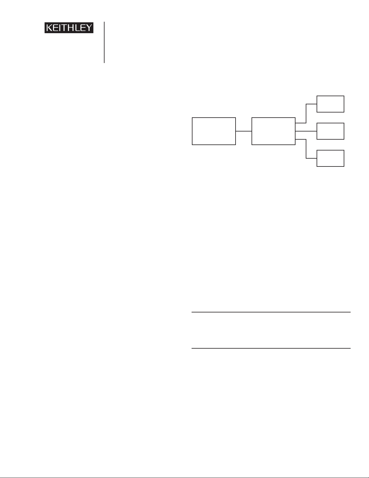
devices, for the purposes of this application note, we will consider a test system consisting of a digital multimeter and a switching device. The system may connect these devices through several ports, such as external trigger lines, input/output signals, and
remote control connections (GPIB, RS-232, etc.) Figure 1 illus-
trates a typical DMM/Switch-based test system.
DMM Configuration
The time required to make the measurement itself is the
first major factor in overall system throughput. When using a
multimeter, several parameters can affect the measurement
speed. While most multimeters have control over many of these
parameters, some of the more “basic” units do not. However, the
factors are the same for the simplest meter or for the most complicated one. It is the level of control of these parameters that is
important for exact measurement timing.
Integration rate—The integration rate is the time it takes the
A/D converter to “look” at the input signal. The integration time
affects the usable resolution, the amount of reading noise, and
the ultimate reading rate of the measurement. The optimum integration time setting for a given application depends on the measurement requirements. If speed is the most important consideration, then the smallest integration rate would be used (0.01
power line cycles or PLCs) at the expense of additional reading
noise and less usable resolution. For maximum common mode
and normal mode rejection, the larger integration rate would be
used (up to 50 PLCs). This would produce the most stable, accurate and highest resolution readings. See Tables 1 and 2 for inte-
gration selections for Series 2000 DMMs.
Table 1. Model 2000 and 2010 Integration Selections
Fast Medium Slow Settings
Model (Front Panel) (Front Panel) (Front Panel) (Remote)
2000 0.1 1.0 10 0.01—10.00
2010 0.1 1.0 5 0.01—10.00
Table 2. Model 2001 and 2002 Integration Selections
Model* Fast Medium Normal HI Accuracy Settings
2001 0.01 0.1 1.0 10 0.01—10.00
2002 0.01 0.1 1.0 10 0.01—50.00
*All settings available on front panel and remote
Ranging—All published measurement rates are stated with a
fixed measurement range. Autoranging should not be used when
optimum speed is required. While some meters have fast
autoranging features, the actual speed is not predictable. Fixed
range is the only way to ensure timing precision.
Filter—All rates are stated with all filters turned off. Although
filtering stabilizes noisy measurements, it also slows the rate of
measurement. The Keithley 2000 Series meters all have digital
filters, which are based on reading conversions. With a digital
Application Note
Series
Figure 1. DMM/Switch Configuration
DUT
DMM Switch
DUT
DUT
Page 2
filter, a DMM takes a number of conversions and averages them
before displaying the result. The number of conversions is the
largest factor affecting rate when using filters. As the number of
conversion averaged increases, the rate decreases.
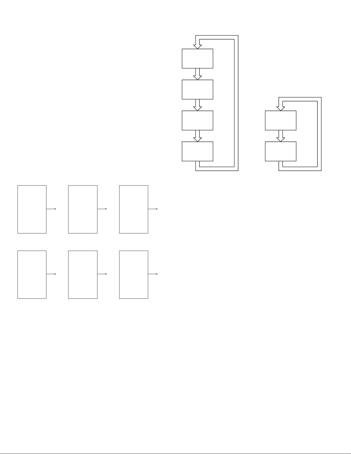
DMMs typically offer two types of filters (Figure 2):
Repeating Filter—A repeating filter takes a selected number of reading conversions, averages them, and yields a
reading. The filter is then cleared and starts collecting conversions all over again.
Moving Filter—A moving filter is a first-in/first-out stack;
in other words, the newest reading conversion replaces the
oldest. An average of the stacked reading conversions
yields a reading. Therefore, after a selected number of conversions, a moving filter gives a new reading for every
new conversion.
The time to the first reading is the same for both types of
filters. After the first reading, the moving average filter produces
a faster rate than the repeating filter.
Figure 2. Filter Types
Autozero—Normally, every A/D conversion has four distinct
periods, as described below. Disabling the Autozero function
eliminates two of these four periods, enhancing measurement
speed.
Signal Integrate During this period, the A/D converter
“looks” at the input signal. The signal integrate period is essentially the PLC setting.
Reference Integrate This is the length of time that the meter
“looks” at the internal reference signal.
This allows a reference to compare the
input signal with a known level.
Zero Integrate This is how long the meter “looks” at the
internal zero. This allows re-zeroing the
input amplifier. This is designed to keep
the signal from drifting over the course of
several conversions.
Calculate This is the period in which the meter
firmware calculates the measurement.
It is normally a very small portion of the
overall conversion.
With Autozero enabled, the A/D conversion sequence
includes all four periods. With Autozero disabled, the A/D conversion does not go through the zero integrate or reference integrate periods. Therefore, the conversion period is much shorter
and the measurement speed is increased. However, it also means
the meter is not checking reference or zero in the A/D conversion, so the reading could drift slightly after a period of time.
The actual drift is a result of small changes in the temperature
of the measurement circuitry. To avoid this drift, keep Autozero
enabled until just before the actual measurement sequence is performed. Re-enable Autozero once the measurement sequence is
completed. This technique keeps the measurement circuitry on
track before and after the measurement. As long as the measurement does not last too long, e.g. longer than ten minutes
(depending on the meter used), the readings shouldn’t drift
enough to affect the accuracy of the measurement.
Figure 3. Typical A/D Conversion Period
Signal
Integrate
Reference
Integrate
Zero
Integrate
Calculate
Signal
Integrate
Calculate
A. Type: Moving Average, readings = 10
Conversion
Conversion
B. Type: Repeating, readings = 10
Conversion
Conversion
#10
#9
#8
#7
#6
#5
#4
#3
#2
#1
#10
#9
#8
#7
#6
#5
#4
#3
#2
#1
Reading #1
Reading #1
Conversion
Conversion
Conversion
Conversion
#11
#10
#9
#8
#7
#6
#5
#4
#3
#2
#20
#19
#18
#17
#16
#15
#14
#13
#12
#11
Reading #2
Reading #2
Conversion
Conversion
Conversion
Conversion
#12
#11
#10
#9
#8
#7
#6
#5
#4
#3
#30
#29
#28
#27
#26
#25
#24
#23
#22
#21
Reading #3
Reading #3
Auto Zero ON
Auto Zero OFF
Page 3
Trigger Delay—In a multiple channel test system, a relay is
used to make the connection to various signals. Relays normally
have bounce or settle times of several milliseconds. Starting the
A/D conversion before the signal is settled could result in a
noisy measurement. The trigger delay is the period from when a
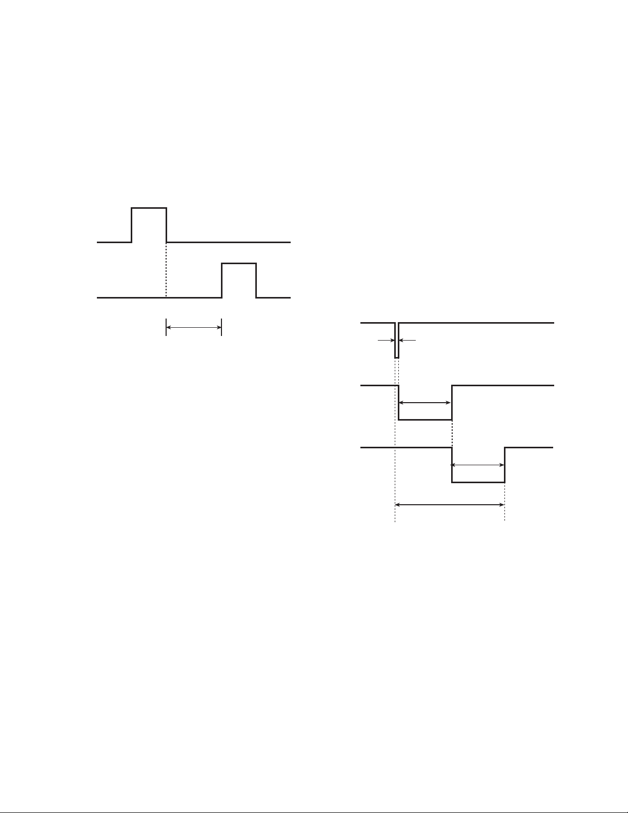
trigger is received to the time the meter starts the A/D conversion (Figure 4). This delay is generally used to allow the input
signal to settle before starting the A/D conversion. Keithley’s
Series 2000 meters have settable trigger delays, which, if applied
carefully, can help optimize measurement integrity and speed.
Figure 4. Trigger Delay
Function—The measurement function to be performed (DCV,
ACV, etc.) is a factor in the measurement rate because each
function is measured using a different technique. In general, the
resistance function takes longer to complete a measurement than
the DCV function, which is simply a single A/D conversion
sequence per measurement. In contrast, the Resistance function
could require several A/D conversion sequences per measurement. If a meter measures temperatures using RTDs or thermistors as temperature sensors, that temperature measurement
function is usually the meter’s slowest function. Typically, DCV
measurement is usually the meter’s fastest function.
Display—Updating the meter’s front panel display takes time, so
turning off the display allows the meter to complete the measurement task faster, particularly meters with information-intensive
displays. These meters typically take up to 5% more time to
update the display. In systems where speed is critical, the display
should be disabled.
In applications where it’s necessary to see the display, the
following technique can be used to optimize speed.
• Enable the display before measurement.
• Disable the display during measurement.
• Re-enable the display after measurement.
The actual measurement is not viewed during the test.
Switch configuration
The next factor affecting test system speed is the switching
time. The switching time is the time it takes to disconnect one
signal and connect another one to the measurement instrument.
Three factors affect switching time (Figure 5). All three factors are
additive in the switch configuration calculation of switch speed.
Settle Time The time it takes for the switching device to
settle. A relay, for example, has a settle time
specification of ≈3ms.
Actuation Time The time required for the switching main-
frame to start closing the switch. The Model
7001 and 7002 have actuation times of ≈6ms.
Trigger Execution The maximum time from activation of
Time (Trigger Trigger Source to start of switch open or
Latency) close. In general, this is several hundred
microseconds.
Figure 5. Switching Times
Total system speed is equal to the DMM configuration
factors plus the Switch configuration factors. For example, to
switch and measure six DC voltages:
Model 2001
• 1 PLC
• 1V range
• No filter
• Autozero Off
• No delay
• DCV function
• Display ON 24 ms
Trigger
Measure
Trigger Delay
Trigger Execution Time
Actuation Time
Settle Time
Total Switch Time
Page 4

Model 7001/7011*
Settle Time = 3ms
Actuation time = 6 ms
Trigger Actuation Time = 0.1ms
33.1ms
per switch/read
*Break-before-make off
For the parameters listed above for the Model 2001 and
7001/7011-S units, the switch/read rate is 33.1 ms per
switch/read. This is about 30 switch/reads per second. The times
for the multimeter and switching equipment were quoted from
the published specifications.
Alternative Solutions
Test systems can be configured with a variety of instrumentation. The Series 2000 Multimeters are just one choice for
setting up the measurement portion of the system. The Series
2400 SourceMeter®instruments and the Model 236/7/8 SMUs
include the source and measure function in one unit. These
instruments allow greater flexibility and, therefore, tighter control of the measurement parameters. These instruments also offer
programmable test current and voltage levels, which some test
parameters require.
If a voltage or current sweep is required, then the Series 2400
and Model 236/7/8 instruments may prove better suited for the test
system. If significantly more resolution and accuracy are required,
then the multimeters will be the better choice of equipment.
The configuration of the switching part of the system
depends on the signal parameters. Many different switch topologies could be used — single pole, double pole, four pole,
high/low current, high/low voltage, matrix, multiplex, high frequency, etc. Keithley has a wide variety of switching cards to
accommodate almost any application or combination of signals.
Equipment List
A typical test set-up would include the following equipment:
1. Keithley Model 2000 Multimeter
2. Keithley Model 7001 Switching Mainframe
3. Keithley Model 7011-S 40-channel switching card
4. PC with Keithley Model KPC-488.2AT IEEE-488
interface card
5. Keithley Model 7007-2 IEEE-488 Interface Cable (2)
6. Test leads to connect the Model 7011-S switch card to the
input of the Model 2000
Conclusion
Measurement and the switch time are major factors in
determining the throughput of a test system. Both factors must be
optimized in order to attain the best overall system throughput.
Keithley Instruments, Inc. • 28775 Aurora Road • Cleveland, Ohio 44139 • 440-248-0400 • Fax: 440-248-6168 • www.keithley.com
BELGIUM: Keithley Instruments BV Bergensesteenweg 709 • B-1600 Sint-Pieters-Leeuw • 32-2-363-00-40 • Fax: 32-2-363-00-64
CHINA: Keithley Instruments China Yuan Chen Xin Building, Room 705 • 12 Yumin Road, Dewai, Madian • Beijing 100029 • 8610-62022886 • Fax: 8610-62022892
FRANCE: Keithley Instruments SARL 3 Allée des Garays • B.P. 60 • 91122 Palaiseau Cédex • 33-1-60-11-51-55 • Fax: 33-1-60-11-77-26
GERMANY: Keithley Instruments GmbH Landsberger Strasse 65 • D-82110 Germering, Munich • 49-89-8493070 • Fax: 49-89-84930759
GREAT BRITAIN: Keithley Instruments, Ltd. The Minster • 58 Portman Road • Reading, Berkshire RG30 1EA • 44-1734-575666 • Fax: 44-1734-596469
INDIA: Keithley Instruments GmbH Flat 2B, WILOCRISSA • 14, Rest House Crescent • Bangalore 560 001 • 91-80-509-1320/21 • Fax: 91-80-509-1322
ITALY: Keithley Instruments SRL Viale S. Gimignano 38 • 20146 Milano • 39-2-48303008 • Fax: 39-2-48302274
NETHERLANDS: Keithley Instruments BV Avelingen West 49 • 4202 MS Gorinchem • 31-(0)183-635333 • Fax: 31-(0)183-630821
SWITZERLAND: Keithley Instruments SA Kriesbachstrasse 4 • CH-8600 Dübendorf • 41-1-821-94-44 • Fax: 41-1-820-30-81
TAIWAN: Keithley Instruments Taiwan 1FL., 85 Po Ai Street • Hsinchu, Taiwan, R.O.C. • 886-3572-9077• Fax: 886-3572-9031
© Copyright 1998 Keithley Instruments, Inc. No. 1985
Printed in the U.S.A. 19810KAP
 Loading...