

Page 1
LC´, CC´, RC´/ft.
RC´ LC´
CC´
Power Supply
Source Leads (twisted pair)
Phone
Test Fixture
Mobile Phone
L, C, R
Parasitic
Fixture
L, C, R
R
cable
L
cable
V
senseVout
ERR AMP
230X
C
cable
C
DUT, fixture
+
–
Sense
OUT
AMP
Number 2870
Application Note
Series
Stabilizing Fast Transient Response
Power Supply/Load Circuits
Introduction
Keithley’s Series 2300 Battery/Charger Simulators (fast transient
response power supplies) are specifically designed for powering
RFIC power amplifiers, mobile phone handsets, and other portable, battery-operated products in R&D and manufacturing environments. These battery-simulating power supplies are designed
to recover very quickly from short-duration pulse load current
changes as large as 1000% (i.e., a 10× increase in load current)
and to measure the peak of the load current pulse. In order to
maintain the output voltage at the programmed output level
despite near instantaneous pulse load changes and to capture
information on pulses as short as 600µs, the power supply must
combine a fast voltage recovery time with minimal voltage droop
from the transient perturbation caused by the fast load current
change. Power supplies like the Series 2300 battery/charger
simulators must have a fast-responding, wide-bandwidth (beyond
200kHz and up to 2MHz) output stage. While this wide-bandwidth supply recovers quickly from large load current changes,
the wide-bandwidth output stage is much more susceptible to
the impedance of the external load circuit than conventional narrow-bandwidth DC power supplies. Certain high reactance load
conditions, such as long wire runs and capacitive loads with low
equivalent series resistance (ESR), can cause the power supply
output to begin oscillating. This paper will describe the various
load circuit conditions that can cause oscillation and provide
methods for stabilizing the load circuit.
The DC Power Supply/
Load Circuit Combination
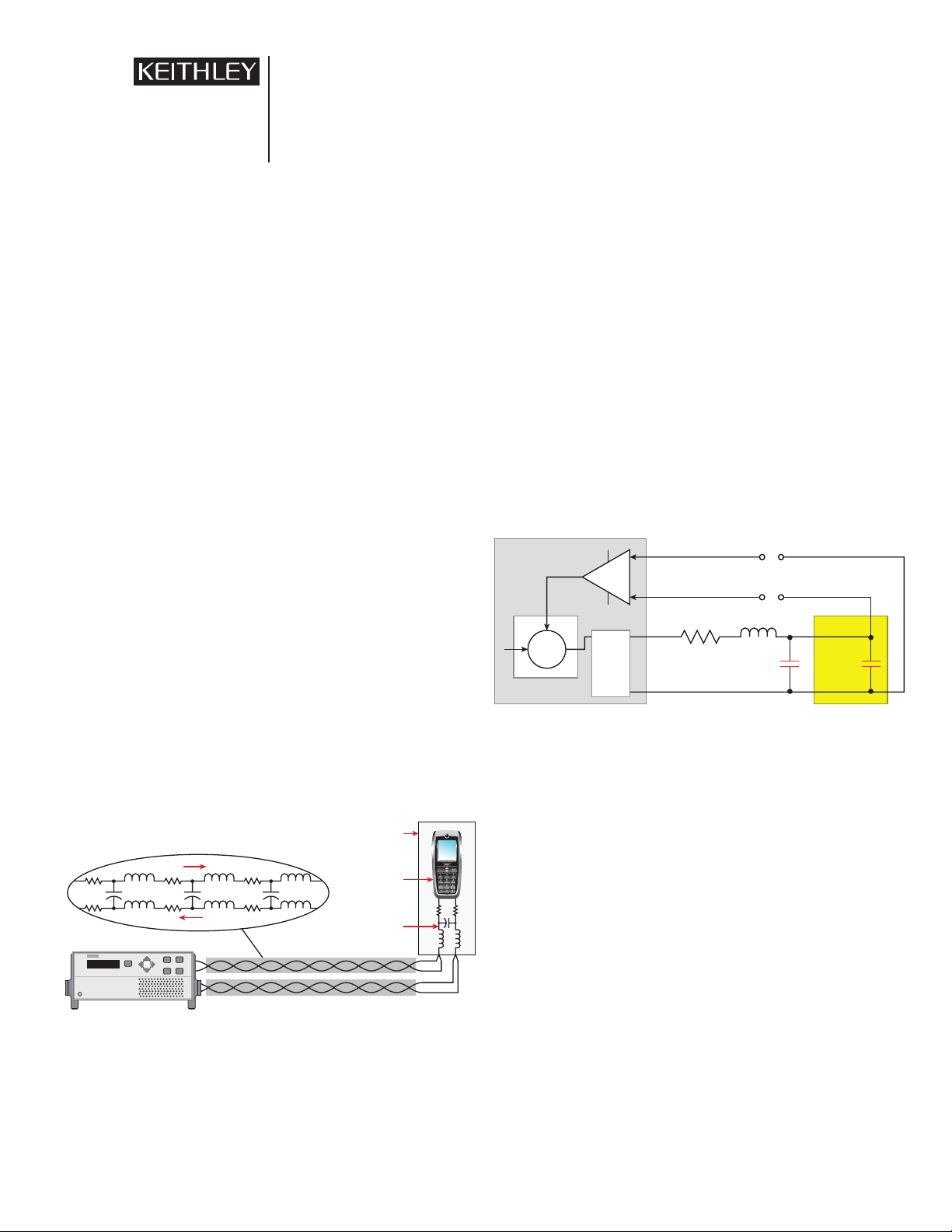
Figure 1. Typical connec tions between a power supply and a DUT. The power
supply is using remote-sense feedback.
Figure 1
supply is energizing a device under test (DUT), in this case, a
illustrates a typical load power circuit in which a power
mobile phone in a test fixture. The power supply is using a fourwire connection scheme consisting of a pair of power sourcing
wires and a pair of load voltage sensing wires. The wires in each
pair are twisted together to minimize spurious voltages resulting from induced magnetic fields. The test fixtures often employ
bypass capacitors to minimize AC noise. To understand how the
load circuit performs for analysis of short load current pulses
(effectively an AC signal), the two pair of wires must be modeled
as an AC network of distributed resistive, series inductive, and
parallel capacitive components. The test fixture and DUT must
be modeled as an AC network as well. The cable capacitance, the
parallel capacitance between the wires, is usually much smaller
than the bypass capacitors added around the DUT, which are
typically on the order of 10µF or larger.
Stability Analysis of the Power
Supply/Load Circuit Combination
Figure 2. Simplified Series 2300 measurement schematic with reactive load
To analyze the Series 2300 power supply/load circuit combination, the overall power supply is modeled as a feedback network
consisting of an ideal error-correcting amplifier, an ideal output amplifier stage, and an ideal feedback sense amplifier (see
Figure 2
the load to force the power supply output to increase its voltage
to overcome the losses in the test leads and fixture to ensure
the desired (or programmed) voltage is applied to the load. The
cables and test fixture connections/DUT are modeled as lumpedelement components with the DUT and test fixture as defined by
the dominant component, the parallel capacitance of the DUT.
plot, which shows the gain and phase performance as a function
of frequency.
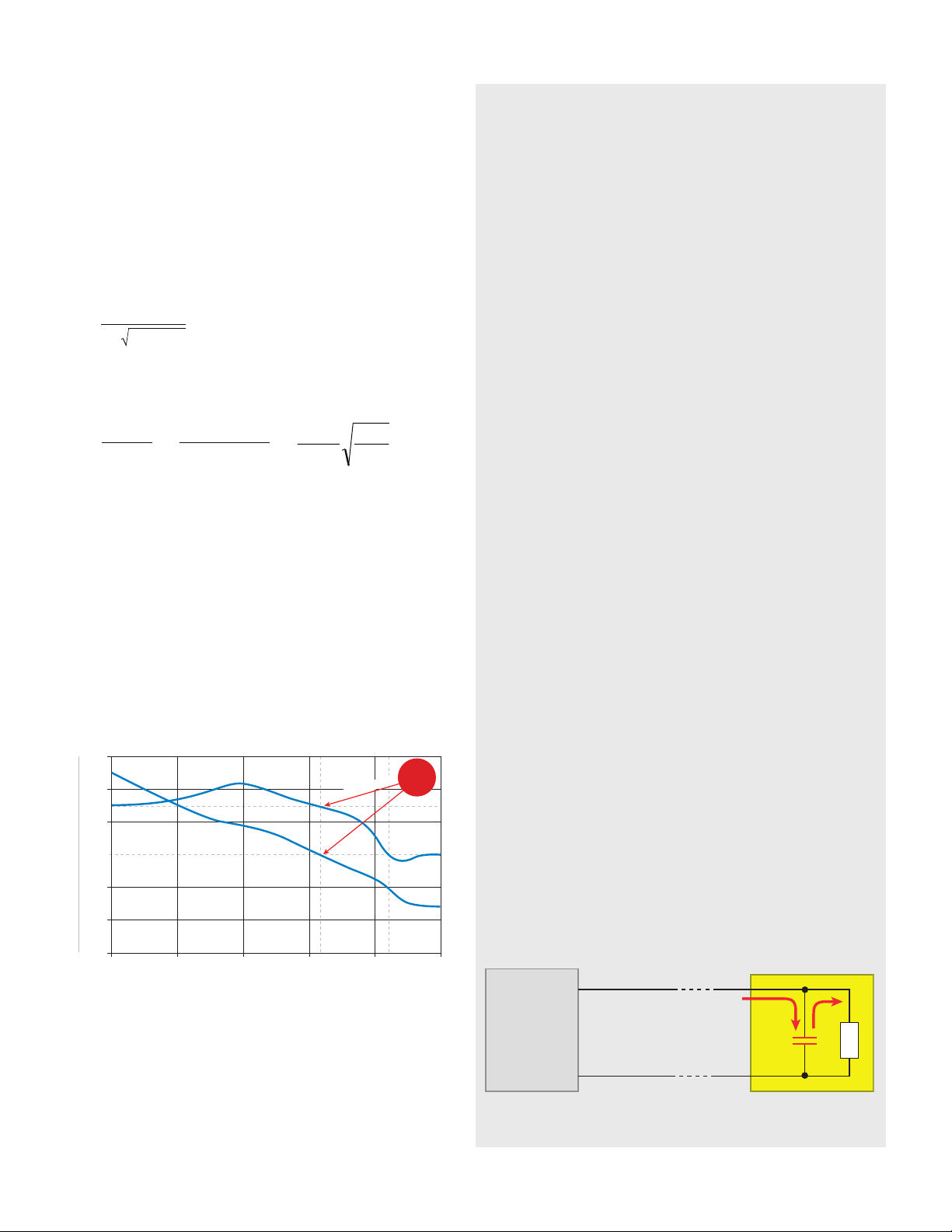
mance of a Model 2306 power supply into an open circuit—effectively, a well-behaved resistive load. The loop gain falls to 0dB
(unity gain) at a frequency slightly greater than 1MHz. If the
loop gain is equal to one, and the output phase is 0º (positive
feedback), the output will be unstable (consult the references in
notes 1 and 3 and any electronics text that discusses the theory
and remote-sense feedback
). The sense amplifier measures the voltage directly at
A feedback network’s performance is characterized by a Bode
Figure 3
shows the loop gain and phase perfor-
Page 2
of feedback circuit design for more information). In the case of
totalcable
res
CL
f
2π
1
=
Cable
cableres
R
L
Qω=
=
=
TotalCableres
CR
ω
1
Total
Cable
Cable
C
L
R
1
60
40
20
0
–20
–40
–60
1kHz 10kHz 100kHz 1MHz 10MHz 100MHz
180°
100°
0°
–100°
–180°
Phase
Gain, dB
Phase
Gain
Phase
margin at
Unity Gain
Frequency
phase@Unity Gai
n
Unity Ga
in
p
oi
n
t
230X
Sen+, Src+
Sen–, Src–
C
bypass
the open circuit load, the Model 2306 has a phase margin of
about 90º above 0º, which ensures the output is stable. Circuit
design rules recommend a phase margin greater than 45º to
guarantee circuit stability under all conditions.
The actual power supply/R-L-C load circuit combination has
a multi-pole transfer function with the bandwidth and the unity
gain point determined by the power supply control loop and
the parameters of the R-L-C load. The L-C load components also
determine the resonant frequency, which is near the frequency of
oscillation. The resonant frequency (fres) is defined as follows:
If the phase margin is near 0º at this frequency, the power
supply output will oscillate. Similarly, at the resonant frequency,
the pole Q factor is:
To maximize the transient response and ensure stability, fres
needs to be greater than the bandwidth of the power supply output circuit, and Q needs to be as small as possible.
The following sections describe methods to ensure a stable
load circuit by effectively extending fres beyond the bandwidth
of the power supply and to minimize Q. The four methods are:
1. Decreasing L
: Using good wiring techniques and low
cable
impedance cable
2. Decreasing C
: Eliminating unnecessary capacitors, typi-
Total
cally on the test fixture
3. Increasing R
: Adding resistance to the load circuit
Cable
4. Adding a compensation network to the load circuit.
Compensating for Inadequate
Power Supply Transient Response
with a Large Load Capacitor
When large capacitors are placed in parallel with the
DUT, the capacitance does improve stability, but there are
significant performance trade-offs involved. Prior to the avail-
ability of fast transient power supplies like the Series 2300,
manufacturers of portable devices such as mobile phones had
to work with conventional power supplies, which do not have
the bandwidth to respond effectively to large, near-instan-
taneous load current changes. The solution to maintaining
a near-constant output voltage was to put a large capacitor
in parallel with the load, essentially to add a second voltage
source in the load circuit (see
values of 100µF to 4700µF typically have a large equivalent
series resistance (ESR) that reduces the Q of the load circuit.
Furthermore, the equivalent series resistance of the capacitor
increases at higher frequencies and effectively adds additional
resistance to the circuit. The increased resistance at high fre-
quencies also acts to reduce Q and greatly enhance circuit sta-
bility. However, there are two disadvantages of using a large
capacitor at the load:
1. The power supply current readback circuit can no lon-
ger be used to measure a pulse load current because
the capacitor is supplying current to the load to hold
the voltage at the load steady.
Figure 4
). Large capacitors with
Figure 3. Model 2306 battery channel/2302 closed-loop gain and phase with
Using Good Wiring Techniques
and Low Impedance Cable
Good wiring techniques minimize the coupling of external
noise into a circuit and should be used in all applications. These
techniques are essential for controlling instability in wide-band-
no load
2. Large electrolytic and tantalum capacitors have large
leakage currents, which prevents the power supply cur-
rent readback circuit from reading sleep mode or off-
state currents accurately.
Although adding a large capacitor at the load can increase
system stability, it is not a desirable solution. Using a fast tran-
sient power supply and removing the capacitor at the DUT
provides the best overall circuit performance.
Figure 4. The impact of a large bypass capacitor at the load when the DUT
load current increases.
Page 3
width power supply/load circuits. Twisted-pair source and sense
R
cable
R
add
R
add
L
cable
DC
230X
C
cable
C
DUT, fixture
+
–
RcCc
f
network
< f
res
π
2
1
=
leads should be used to reduce unwanted coupling from nearby
interference sources and offer immunity to both electric and
magnetic fields. Twisting the conductor pair between source
and load minimizes the loop area, which limits the magnitude
of induced voltages and cancels these noise voltages because
they are of equal magnitude and opposite polarity in adjacent
twists. Consequently, twisted wire pairs provide better immunity
to magnetic fields than two closely spaced parallel conductors.
Moreover, twisted wire pairs reduce the emission of magnetic
fields. The current flow in the two close proximity wires is equal
and opposite, so the resulting magnetic fields effectively cancel
each other within a few inches of the pair. The twisted wire pair
has lower inductance than an untwisted pair of wires of equal
length. Typically, the inductance of a 15-foot-long (4.6m) twistedpair cable is 2–4µH.
To minimize inductance in a given length of twisted-pair
wire, use wire with thin Teflon® insulation. Thin insulation
minimizes the loop area of the twists; and, Teflon is an insulator
with a low dielectric constant, which provides the added benefit
of minimizing the cable’s capacitance and reduces total cable
impedance.
Adding Resistance to the Load Circuit
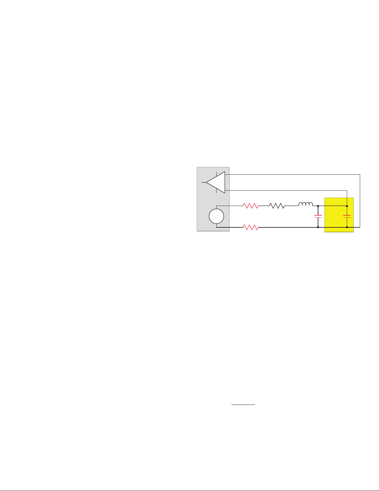
Increasing the resistance in the load circuit reduces Q and can
enhance stability.
the addition of two resistors to the load circuit. A recommended
maximum value is 1Ω for each resistor. Using the least resistance
necessary to achieve stability is optimal; thus, if 1Ω stabilizes the
load circuit, experiment with lesser-value resistors to find the
smallest acceptable value. A small additional voltage drop in each
source lead can be overcome by the sense detection feedback
network and the error correction circuitry that ensures the voltage at the load is maintained at the programmed value. Another
way to increase the load circuit resistance is to use thinner gauge
wire. Either method for increasing R adds damping to the circuit.
Therefore, although added resistance can improve stability, it
also increases the load circuit time constant and the power supply settling time.
Figure 5
shows the recommended location for
Another way to lower cable inductance is to keep the cable
as short as possible. The closer the fixture/DUT is to the power
supply, the lower the total cable inductance. Obviously, there are
physical limitations on how close the DUT can be to the power
supply, but routing the cabling as directly as possible to keep the
cable length as short as possible helps ensure system stability.
If using twisted-pair wire and the shortest possible cables is
not sufficient to ensure stability, low inductance cables can be
used. Keithley’s Model SC-182 low inductance coaxial cable with
Teflon insulation has a 10Ω characteristic impedance. A 4.6m
length of this cable has 150–250nH of inductance. When compared with standard twisted cable, this is a reduction in inductance of an order of magnitude.
Using Teflon®-insulated twisted-pair wires, minimizing wire
length, and using the SC-182 low inductance cable help reduce
L
and enhance load circuit stability. However, using these
Cable
solutions does not alter the performance of the power supply/
load circuit combination.
Decreasing the Capacitance in the
Load Circuit
Figure 5. Adding two resistors to Series 2300 source leads to improve
stability.
Adding a Compensation Network
to the Load Circuit
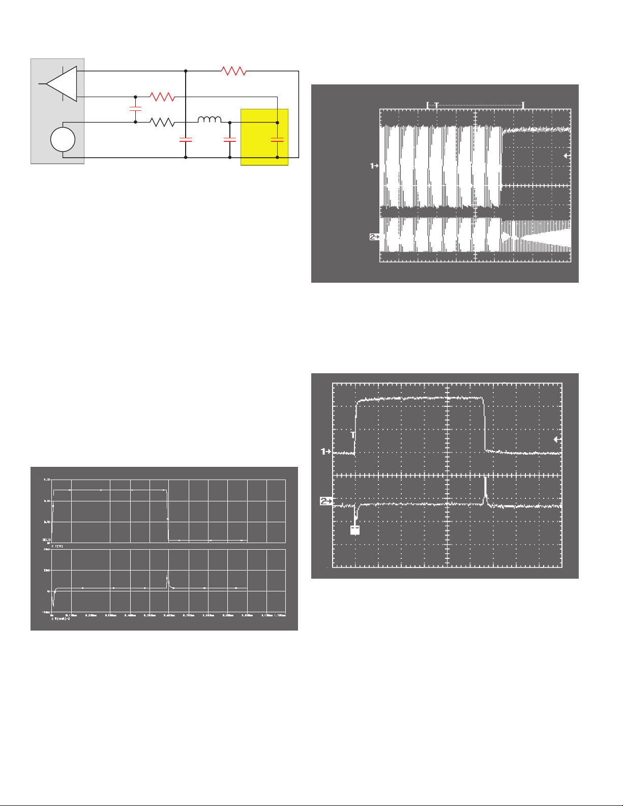
A third method for improving stability involves adding two R-C
compensation networks near the power supply between corresponding sense leads and source leads (see
technique bypasses the cable inductance and load capacitance
of the feedback network for frequencies higher than the circuit
resonant frequency (f
). The compensation capacitors (Cc) act
res
as a low impedance path for the high frequency components of
the voltage waveform as it changes due to the load current transitions. Compensating capacitors effectively close the feedback
loop of the power supply/load circuit combination at approximately fres and stabilize the circuit.
To compensate the power supply/load circuit combination
with this network, the 3dB point of the low pass compensation
network filter must be less than f
. Thus,
res
Figure 6
). This
Wherever possible, eliminate any capacitors in parallel with the
DUT. The Series 2300 power supplies have the wide bandwidth
and resulting fast transient response needed to maintain the
voltage at the DUT during state transitions without the help of a
parallel capacitor at the DUT. Eliminating capacitors reduces the
total capacitance in the load circuit, so removing a parallel capacitor at the DUT will improve the load circuit’s performance.
A recommended staring point is to set Rc to 100Ω, then
determine an appropriate value of Cc to stop oscillation. Given
that the sense feedback amplifier draws very little current,
the 100Ω resistors create minimal error in the voltage at the
DUT. While this is an effective method for improving stability,
Page 4
C
C
R
C
R
cable
L
cable
Sense –
R
C
Sense +
Source +
DC
230X
Source –
C
C
C
cable
C
DUT, fixture
+
–
Figure 6. Adding two compensation net works
this method reduces the effective bandwidth and the transient
response of the power supply/load circuit network.
In addition to the external compensation network, the Model
2302 and Model 2306 power supplies offer internal bandwidth
control to improve load circuit stability. The HIGH bandwidth
setting produces the fastest transient response with dynamic
loads. The LOW bandwidth setting (default instrument state) will
have a slower response but will be more stable for most loads.
The LOW bandwidth setting internally implements the compen-
sation capacitance technique shown in
Figure 6
.
Actual Instability Problem and
the Stabilizing Solution
Figure 7
curve) to a 1A load current pulse. The load is resistive and cable
length is negligible (the load is connected directly at the power
supply output terminals). The voltage at the load exhibits a 10mV
droop and 10mV overshoot in response to the rising edge and
falling edge of the load current pulse. This is as close to the ideal
response as can possibly be achieved.
depicts the actual system voltage response (lower
power supply/load circuit combination will be unstable and the
voltage at the load will oscillate as shown in
Load
Current
0.5A/Div
Load
Voltage
10mV/Div
Time 0.1ms/Div
Figure 8. System instability (Lcable =1µH , C
DUT
= 2µF)
Figure 8
.
In this case, replacing the power supply load wire pair with
the Keithley Model SC-182 Low Inductance Cable reduces the
load impedance sufficiently to stabilize the circuit.
Figure 9
shows the resulting response to the load current pulse.
Load
Current
0.5A/Div
Load
Current
0.4A/Div
Load
Voltage AC
Response
10mV/Div
Time 0.1ms/Div
Figure 7. Transient response with resistive load and negligible cable length.
A more realistic situation involves cable lengths between the
power supply and the DUT that can range from hundreds of
nanohenrys to several microhenrys. In addition, the capacitance
on the fixture and the DUT input capacitance can be as high as
tens of microfarads. At these impedance levels, the system can
be unstable. For example, with L
cable
=1µH and C
DUT
Load
Voltage
10mV/Div
Time 0.1ms/Div
Figure 9. System stabilized (122cm. SC-182 cable, C = 2µF)
= 2µF, the
Page 5

Suggested Solution Sequence for Stabilizing
the Power Supply/Load Circuit Combination
Following this suggested order of steps can help solve power
supply/load circuit stability problems:
Eliminate any capacitors on the test fixture and across the
1.
DUT wherever possible.
Reduce the inductance of the power supply wiring by using
2.
wiring with Teflon insulation where possible. Alternatively,
use the SC-182 coaxial cable with Teflon insulation. Use
good wiring techniques and minimize the length of the
wiring to the DUT.
If using either a Model 2302 or a Model 2306, try switching
3.
to the LOW bandwidth setting to activate the internal compensation network.
If an oscillation is occurring at a frequency lower than
4.
100kHz (when using the Model 2303) or lower than
500kHz (when using the Model 2306), then try using an
external compensation network.
If an oscillation is occurring at a frequency higher than
5.
100kHz (when using the Model 2303) or higher than
500kHz (when using the Model 2306), try adding resistance to the power supply/load circuit. Start with 1Ω in
each source wire. If the 1Ω resistor stabilizes the circuit,
experiment with smaller values until the circuit becomes
unstable again, then choose a slightly larger value that restabilizes the circuit. The objective is to minimize the level
of additional resistance in the circuit to optimize transient
response. Remember that using a thinner gauge lead wire
could add sufficient resistance to accomplish the same goal
as adding resistors to the circuit.
The order of these steps is such that the initial steps have
the least impact on circuit performance. Any of the techniques
can be used in conjunction with others to resolve more difficult
power supply/load circuit combinations.
Summary
While fast transient response power supplies provide the necessary performance to quickly recover from large pulse load
currents, the wide bandwidth of these supplies makes them
susceptible to instability in high reactance load circuits. The load
circuit reactance is a function of the type of lead wire used, the
length of the wire leads, components on the fixture, and the
input reactance of the DUT. The combined reactance of these
circuit elements must be minimized to obtain the full performance of the fast transient power supply. Methods to reduce the
reactance include reducing cable inductance by minimizing the
length of the cable or, for best results, using the Model SC-182
low inductance cable. Increasing the load circuit resistance is
a second technique to improve stability. Using a thinner gauge
cable or adding a small resistor in each source line accomplishes
the objective of increasing the resistance in the load circuit.
Eliminating unnecessary fixture capacitors reduces total circuit
reactance and is the third technique. The fourth technique for
improving stability involves adding a compensation network to
the circuit to reduce the effective bandwidth of the circuit. Used
individually or together, these four techniques can ensure power
supply/load circuit stability and provide both a voltage output
with minimal variation during dynamic load changes and measurements of DC and pulse load currents. The advantages of fast
transient response power supplies far outweigh the additional
effort in load circuit configuration to ensure stable performance.
Endnotes
1. Keithley Instruments W hite Paper, Optimizing Test Performance Of Digital
Cellular Products With Ultra-High Speed Power Supplies, 2001, available at
ww w.keithley.com/data?asset=4643, retrieved July 26, 2007.
2. Campbell Scientific, Inc. White Paper, Preventing and Attacking Measurement
Noise Problems, 2001, available at ww w.campbellsci.com/documents/
whitepapers/mnoise.pdf, retrieved July 26, 2007.
3. Spectrum Software, Plotting Loop Gain And Phase Margin, available at
http://www.spectrum-soft.com/news/winter2001/loopgain.shtm, 2001,
retrieved July 26, 2007.
Page 6

All Keithley trademarks and trade names are the property of Keithley Instr uments, Inc .
All other trademarks and trade names are the propert y of their respective companies.
Specifica tions are subject to change without no tice.
A G R E A T E R M E A S U R E O F C O N F I D E N C E
KEI TH LEY INSTRUMEN TS, INC. ■ 28775 AUR OR A ROAD ■ CLEV ELAND , OHI O 44139 -1891 ■ 440- 248 -04 00 ■ Fax: 440-2 48- 6168 ■ 1- 888-K EIT HL EY ■ ww w.ke ithle y.com
BE LG IUM
Sint-P ie te rs -L ee uw
Ph : 02-363 00 40
Fax: 02-363 00 6 4
www .kei th le y.nl
CH INA
Be ij in g
Ph : 8610 -822 55010
Fax: 8610- 82 255 018
www .kei th le y.com.cn
FI NLA ND
Es po o
Ph : 09 -88171661
Fax: 09- 881716 62
www .kei th le y.com
FR ANC E
Sa in t- Au bi n
Ph : 01-64 53 20 20
Fax: 01- 60 -11-77-2 6
www .kei th le y.fr
GE RMA NY
Ge rm er in g
Ph : 089- 84 93 07- 40
Fax: 089-8 4 93 07- 34
www .kei th le y.de
IN DIA
Ba ng al ore
Ph: 080-26771071-73
Fax: 080-26771076
www .kei th le y.com
ITALY
Mi lano
Ph: 02-553842.1
Fax: 02-55384228
www .kei th le y.it
JA PA N
Tok yo
Ph: 81-3-5733-7555
Fax: 81-3-5733-7556
www .kei th le y.j p
SW EDEN
So ln a
Ph: 08-50 90 46 00
Fax: 08 -655 26 10
www .kei th le y.com
KORE A
Se ou l
Ph: 82-2-574-7778
Fax: 82-2-574-7838
www .kei th le y.co.k r
SW ITZ ER L AN D
Zü ri ch
Ph: 044-821 94 44
Fax: 41-44-820 30 81
www .kei th le y.ch
MA LAYS IA
Kuala Lumpu r
Ph : 60 -3 -4 041-0 899
Fax: 60- 3- 40 42-0 899
www .kei th le y.com
TAIWAN
Hs in chu
Ph: 886 -3-572-9077
Fax: 886 -3-572-9031
www .kei th le y.com.tw
NE THE RL AND S
Go ri nc he m
Ph: 0183-63 53 33
Fax: 0183-63 08 21
www .kei th le y.nl
UN ITE D KI NGDOM
Th ea le
Ph : 0118-929 75 0 0
Fax: 0118-929 75 19
www .kei th le y.co.uk
SI NG APO RE
Singapore
Ph: 65-6747-9077
Fax: 65-6747-2991
www .kei th le y.com.sg
© Copyright 2007 Keithley Instruments, Inc. Printed in the U.S.A. No. 2870 0807
 Loading...