

Page 1
INSTRUCTION MANUAL
MODEL 153
MICROVOLT-AMMETER
@COPYRIGHT 1974
J+ZEITHLEY INSTRUMENTS. INC.
Page 2
CONTENTS
MODEL 153
SECTION
SPfTCIFICATIONS __-_-_____---__________________--
GENERAL DESCRIPTION _____--______-______----
1.
(-,pE~TION _______-__---______---------------
2.
APPLICATIONS __-______-__-_______-----------
3.
CIRCUIT DESCRIPTION ___-_______________-----
4.
SERVICING __-_____-___________-------------
5.
C&IBuTION _--_________--________--__-_---
6.
ACCESSORIES -_--___________--_______________
7.
REpuCpygjLE PARTS -------------------------
8.
SCHpJ.fATIC _____-_______-__-------------------
PAGE
iv
3
12
13
17
23
33
37
45
1174
Page 3
MODEL 153
ILLLlSTRATIO!&
ILLUSTRATIONS
'i . Vo . .
Title
1 Model 153 Front Panel. ______________-_-_-_------------------2
Front pane1 Controls. -______----_---___--_----------------------
3 Rear panel Terminals. --___----_________--_____---------------_4 Thermal Sink Construction. _--___-_______-_____------------------
5 Using Model 153 with 4-Terminal Connections. ----_--------__-----
6
Null Circuit and Leeds and Northrup K3 Potentiometer. ----------7 Diagram Showing Currents in Solid State Circuits. --------------8 Circuit for Semiconductor Resistivity Measurements. ----- -------9 Model 153 Block Diagram. ____-___-___________________________
10 Wave Form at Junction of Diodes D301 and 0302. ----------------11
Wave Form at Junction of Resistor R302 and Capacitor C302B.
12 Wave Form at -13 Volt Supply. __--____________---_---------------13 Divider Connection for Multivibrator Frequency Adjustment. ------14 Wave Form of Multivibrator Output. --------------------------
15
lb
17
Wave Form for Tuned Multivibrator Output Across Resistor R121. ---
Wave Form for Input Modulator ElOl.
----------------------------
Demodulator Wave Form for Full-Scale Input on l-Volt Range.
18 Typical Model 153 Drift Chart. _____-_-_____-___-__----------19
20 Model 153 Inter&,=. __-_______--______-___----------------------21
22
23
24
25
26
27
28
29
30
31
32
33
Model 153 Interior. ----__--------_-_--------------------------
Capacitor, Tube, Battery, and Modulator Locations on PC-lob. -----
Resistor Locations on Printed Circuit Board PC-lob. ---- - ----- --
Component Locations for Printed Circuit Board PC-107.
_--_____Component Locations on Model 153 Rear Chassis Panel. ---- ----- -Component Locations on Range Switch Sl.
component Locations on Range Switch Sl.
-_------__------------_____-______-_-___-_---
Component Locations for Model 153 Power Supply and Multivibrator.
Keithley Instruments Model 1531 Gripping Probe. -_--_---_-e-s-Keithley Instruments Model 1532 Test Leads. ----___-----------Keithley Instruments Model 1533 Mating Connector. -------------Model 1483 Low-Thermal Connection Kit. _____-______________---Keithley Instruments Model 6012 Triaxial-to-Coaxial Adapter. _---Exploded View of Model 4005 Rack Mounting
Kit. ___-_____-____----
------
-----
Pap*
7
4
5
10
11
1:
12
12
13
16
18
18
20
20
20
20
21
25
26
27
28
29
30
30
31
31
32
33
33
33
34
34
35
1174
iii
Page 4
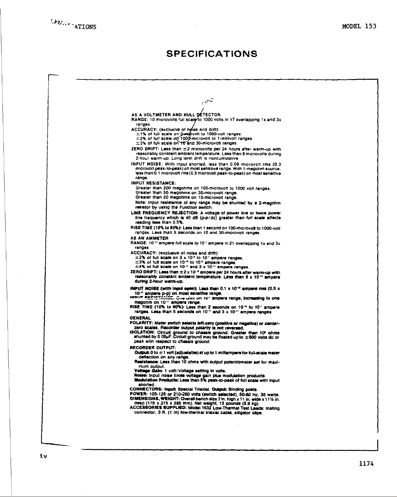
SPECIFICATIONS
MODEL 153
Page 5
KEITHLEY INSTRUMENTS.
INSTRUCTION MANUAL
CHANGE NOTICE
MODEL 153 MICROVOLT-AMMETER
INTRODUCTION: Since Keithley Instruments is continually improving pro-
duct performance and reliability, it is often necessary to make changes
to Instruction Manuals to reflect these improvements. Also, errors in
Instruction Manuals occasionally occur that require changes. Sometimes,
due to printing lead time and shipping requirements, we can't get these
changes immediately into printed Manuals. The following new change in-
formation is supplied as a supplement to this Manual in order to provide
the user with the latest improvements and corrections in the shortest
possible time.
to a Manual to minimize user error.
cated
Page 41, Replaceable Parts, Resistors should read as follows:
R172
R173
Pages 38 s 39, Replaceable Parts, Diodes, should read as follows:
D303
D304
in italics.
9.9kn O.l%, 1/3w w
100 n
Rectifier, l.OA, 8OOV lN4006
Rectifier, l.OA, 6OOV IN4006
Many users will transfer this change information directly
All changes or additions are indi-
O-l%, 1/3w w
15909
15909 1250-100R
1250-9.9KR
R-110-9.9??
R-110-100
MOT RF-38
MOT RF-38
I LN c.
22
22
27
27
Page 6
MODEL 153
GENERAL DESCRIPTIO1i
SECTION 1.
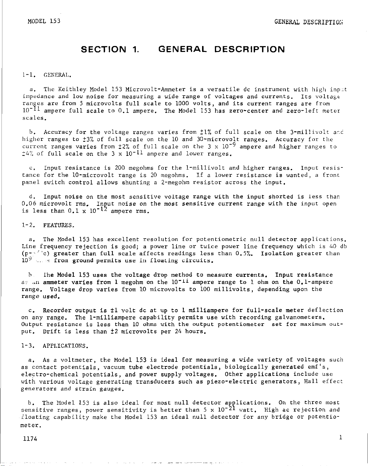
l-l. GENIZAL.
The Keithley Model 153 Microvolt-Ammeter is a versatile dc instrument with high inp,:t
a.
impedance and low noise for measuring a wide range of voltages and currents.
ranyes are from 5 microvolts full scale to 1000 volts, and its current ranges are from
?l
lo-
scales.
higher ranges to ?3% of full scale on the 10 and 30-microvolt ranges.
current ranges varies from +2% of full scale on the 3 x 10v9
24% of full scale on the 3 x lo-11 ampere and lower ranges.
tance for the lo-microvolt range is 20 megohms. If a lower resistance is wanted, a front
panel switch control allows shunting a 2-megohm resistor across the input.
0.06 microvolt rms. In ut noise on the most sensitive current range with the input open
is less than 0.1 x lo-
ampere full scale to 0.1 ampere.
Accuracy for the voltage ranges varies from 21% of full scale on the 3-millivolt a-.?
b.
Input resistance is 200 megohms for the l-millivolt and higher ranges. Input resis-
c.
Input noise on the most sensitive voltage range with the input shorted is less thar.
d.
13
ampere rms.
GENERAL DESCRIPTION
Its voltage
The Model 153 has zero-center and zero-left meter
Accuracy for tjle
ampere and higher ranges to
1-2.
Line frequency rejection is good; a power line or twice power line frequency which is 40 db
(p-:~“c) greater than full scale affects readings less than 0.5%. Isolation greater than
10') -..,~s from ground permits use in floating circuits.
a:: .in ammeter varies from 1 megohm on the lo-L1 ampere range to 1 ohm on the O.l-ampere
range. Voltage drop varies from 10 microvolts to 100 millivolts, depending upon the
range used.
on any range. The l-milliampere capability permits use with recording galvanometers.
Output resistance is less than 10 ohms with the output potentiometer set for maximum out-
put.
l-3. APPLICATIONS.
as contact potentials, vacuum tube electrode potentials,
electro-chemical potentials, and power supply voltages.
with various voltage generating transducers such as piezo-electric generators, Hall effect
generators and strain gauges.
FEATURES.
The Model 153 has excellent resolution for potentiometric null detector applications.
a.
h
The Model 153 uses the voltage drop method to measure currents.
Recorder output is fl volt dc at up to 1 milliampere for full-scale meter deflection
=.
Drift is less than +2 microvolts per 24 hours.
As a voltmeter, the Model 153 is ideal for measuring a wide variety of voltages such
a.
biologically generated emf's,
Other applications include use
Input resistance
The Model 153 is also ideal for most null detector applications.
b.
sensitive ranges, power sensitivity is better than 5 x lo-21 wtt.
~iloating capability make the Model 153 an ideal null detector for any bridge or potentio-
meter.
1174
On the three most
High ac rejection and
1
Page 7
I
GENERAL DESCRIPTION
MODEL 153
2
FIGURE 1,
Model 153 Front Panel.
1174
Page 8
MODEL 153
OPERATION
SECTION 2. OPERATION
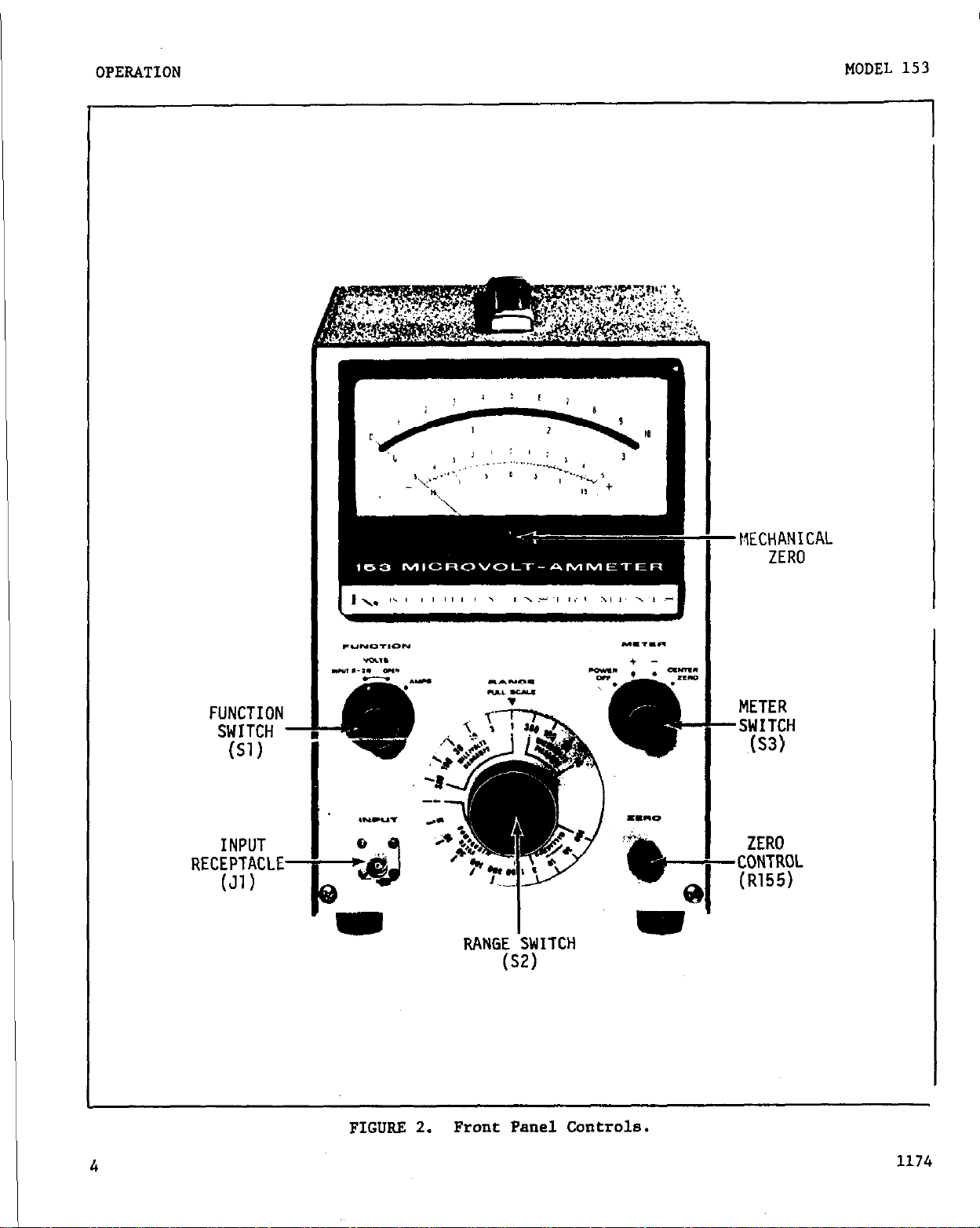
2-1. FRONT PANEL CONTROLS AND TERNINALS.
a. METER Switch. The METER Switch has four positions. POWER OFF shuts off the in-
strument; this also short circuits the meter,
ment.
for center zero operation (lower meter scales).
b.
and one for current inputs. In the VOLTS INPUT R-2M position,
proximately 2 megohms.
mum for the range being used.
tions as an ammeter.
c.
one of 17 voltage and 21 current ranges.
to full-scale deflection for the range selected with the RANGE Switch.
METER + and METER - determine meter polarity.
FUNCTION Switch. The FUNCTION Switch has three positions, two for voltage inputs
In the VOLTS R-OPEN position, input resistance is at the maxi-
(See Table 1.) In the AMPS position, the Model 153 func-
RANGE Switch. The RANGE Switch selects the full-scale instrument sensitivity for
allowing accurate mechanical zero adjust-
CENTER ZERO sets the instrument
input resistance is ap-
The 10 or 3 of the top meter scale corresponds
d. ZERO Control.
20 microvolts,
higher ranges use a 1OOO:l divider,
range.
e. INPUT Receptacle. The INPUT Receptacle is a Teflon-insulated Triaxial type con-
nector. Its center terminal is the circuit high; the inner shield is circuit low (circuit ground); the outer shield is chassis ground.
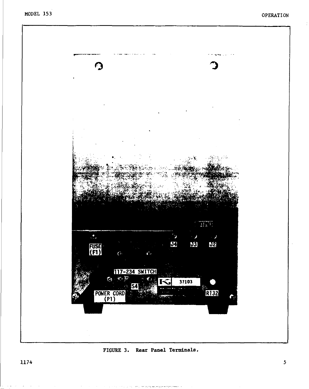
2-2.
a. DC OUTPUT ADJ Control.
Both the output
from 0 to 1.05 volts; output resistance varies to 7.5 kilohme maximum.
b. Output Binding Posts.
f;r case ground; LO is circuit ground; HI is the output connection.
!-:: link is for connecting the LO Post to the G Post.
C. 117-234 Switch. The screwdriver-operated slide switch sets the Model 153 for 117
or 234-volt ac power lines.
d.
210-250 volt operation, use a l/4 ampere, 3 AG Slow Blow fuse.
It has much less effect on other ranges.
REAR PANEL CONTROLS AND TERMINALS.
FUSE. For 105-125 volt operation, use a l/2 ampere, 3 AG Slow Blow fuse.
so it is most effective on the microvolt ranges. Since the II-volt and
voltage
The ZERO Control allows precise meter zeroing. Its range is about
the Control is also somewhat effective on the 3-volt
This Control sets the amplitude of the output voltage.
and reszstance vary wxtn the control setting. Voltage span is
Three posts are used for the l-volt recorder output. G is
The furnished short-
For
e. Power Cord. The 3-wire power cord with the NEMA approved 3-prong plug provides a
ground connection for the cabinet. An adapter for operation from 2-terminal outputs is
provided.
NOTE
The Model 153 INPUT Receptacle is a Triaxial connector.
nect bnc-type connectors to it may damage both.
1174
Any attempt to con-
3
Page 9
OPERATION
MODEL 153
FUNCTION
SWITCH -
(S1)
INPUT
RECEPTACLE-
(Jl)
-MECHANICAL
ZERO
METER
-SWITCH
.(S3)
ZERO
-CONTROL
(R155)
I I
RANGE SWITCH
(S2)
FIGURE 2.
Front Panel Controls.
Page 10
I
MODEL 153
OPERATION
- ..-. ,.
3
FIGURE 3.
Rear Panel Terminals.
Page 11
OPERATION MODEL 153
2-3. PRELIMINARY PROCEDURES.
Check the 117-234 Switch and the Fuse for the proper ac line voltage.
a.
Set the controls as follows:
b.
METER Switch
POWER OFF
RANGE Switch 1 VOLT
FUNCTION Switch
Check meter zero.
Connect the power cord and set the METER Switch to +.
C.
If necessary,
needle should be at zero with the input shorted.
VOLTS INPUT R-2M
adjust with the meter mechanical zero.
If the meter is not exactly at zero
with the input shorted after approximately 20 minutes,
tentiometer, R125 for exact meter zero.
(See paragraph 5-5.) For maximum accuracy, al-
low the Model 153 to warm up approximately 30 minutes.
To cancel any zero offset,
d.
Adjust the front panel ZERO Control.
ty.
2-4.
for all ranges,
VOLTAGE MEASUREMENTS.
Voltage measurements can be made with either of two input resistances:
a.
or a higher resistance, from 20 megohms to 200 megohms depending upon
short the input high to low and reduce
the range.
Generally, it is better to use the higher input resistance (obtained by setting
1.
the FUNCTION Switch to VOLTS OPEN).
To maintain the accuracy of measurements, the input resistance should be 100 times the source resistance.
resistance by ranges.
Within one minute, the
meter
adjust the internal BIAS ADJ Po-
meter
sensitivi-
2 megohms
(See Table l-l for input
With the higher input resistance,
2.
open due to extraneous sisal pickup.
soma meter deflection may occur with the input
To reduce this pickup and also to speed recovery
from input overloads when measuring low impedance sources, use the 2:megohm input resistance (obtained by setting the FIJNCTION Switch to VOLTS (R-2M).
Connect the voltage source to the INPDT Receptacle. Use properly shielded and
b.
grounded leads. Refer to paragraphs 2-8 and following for suggestions and cautions.
Set the RANGE Switch to the highest voltage range. Turn the METER Switch to CENTER
c.
ZERO for the correct polarity for the input signal. Increase the Model 153 sensitivity
until the meter shows the greatest on-scale deflection.
On the 3-volt and higher ranges,
the Model 153 will withstand overloads to 1000 volts without damage. On the lower ranges,
momentary overloads to 1000 volts will cause only temporary instability and zero offset.
Prolonged overloads will damage components and cause increased noise and slower response
speeds.
I
6
1174
Page 12
MODEL 153
OPERATION
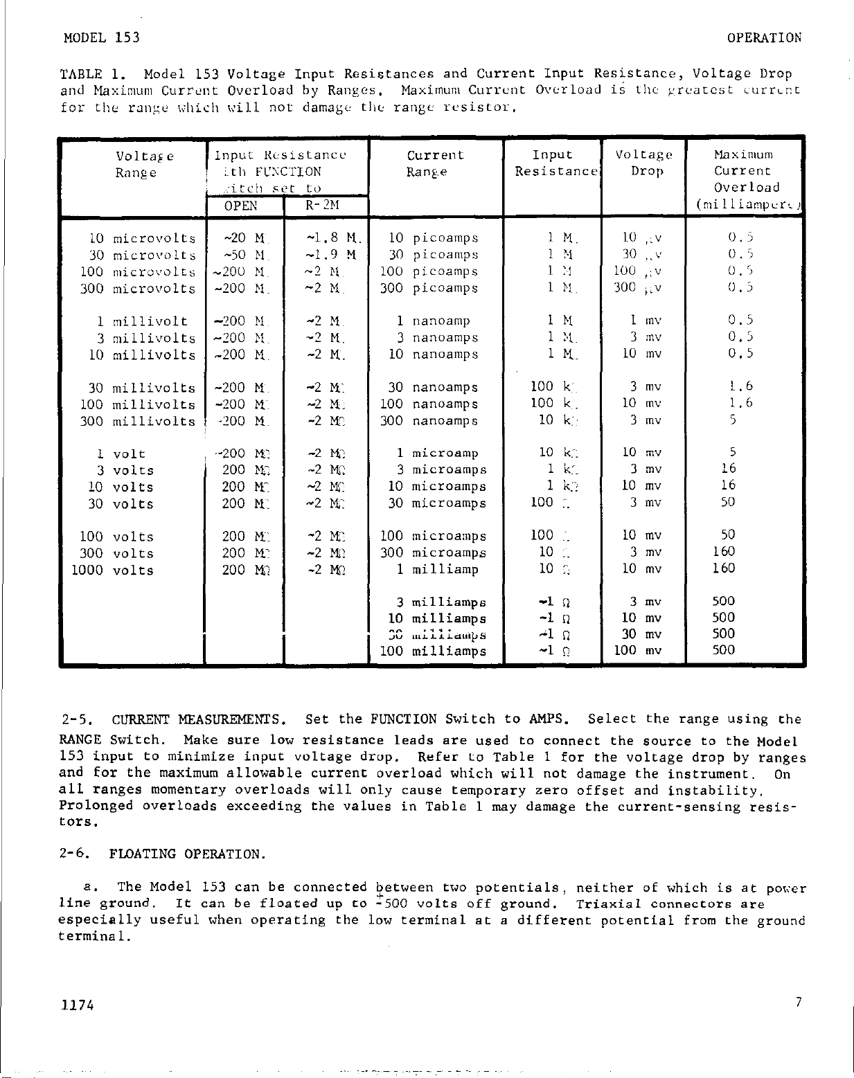
TABLE 1.
and Maximum Current Overload by Ranges.
Model 153 Voltage Input Resistances and Current Input Resistance, Voltage Drop
Maximum Current Overload is tllc p,r~'atcst curr~p.t
for the ralli;e xliich will not damage tliti range resistor.
vo1tag e
Range
Inpur Rcsistancc current Input
:~tll FLTC'rION
Renfie
Resistance
Voltage
Drop GUI-rent
..:itcll sft to
OPEN
R-211
10 microvolts -20 Mu -1.8 M. 10 picoamps 1 M. 10
,I"
(milliampcr:
30 micro\~i,lts -50 M -1.9 x 30 picoamps 1 ?1 30 ,.v 0 . i
100 microi~olts -200 hl~ -2 El 100 picoamps 1 T.1 100 ,:v 0.5
300 microvolts -200 )I. -2 Mu 300 picoamps 1 bl, 300 ;i" 0 . 5
1 millivolt -200 M -2 M 1 nanoamp 1 hl 1 m\ 0.5
3 millivolts -200 K -2 M. 3 nanoamps 1 x 3 rn" 0.5
10 millivolts -200 M. -2 M. 10 nanoamps 1 Mu 10 mv 0.5
30 millivolts -200 Mu -2 MY 30 nanoamps 100 k:~ 3 mv 1.6
100 millivolts -200 Mu -2 M. 100 nanoamps 100 k~. 10 mv 1.6
300 millivolts -700 Mu -2 M' 300 nanoamps 10 k:: 3 mv 5
1 volt
-200
i
M:
-2 M? 1 microamp 10 k:. 10 mv 5
3 volts 200 MT -2 MC 3 microamps 1 kl. 3 rn" 16
10 volts 200 M: -2 MS 10 microamps 1 k:: 10 mv 16
30 volts 200 Mu: -2 I-Ii: 30 microamps 100 1. 3 mv 50
Maximum
Overload
0.5
100 volts 200 M: -2 w 100 microamps 100 :. 10 mv 50
300 volts 200 M1 -2 Ml? 300 microamps 10 1. 3 mv 160
1000 volts 200 M? -2 I% 1 milliamp 10 7. 10 mv 160
3 milliamps -1 n 3 mv 500
10 milliamps -1 R 10 mv 500
X rnil.~icatupS 21 R 30 mv 500
100 milliamps -1 r! 100 mv 500
2-5. CURRENT MEASUREMENTS.
Set the FUNCTION Switch to AMPS. Select the range using the
RANGE Switch. Make sure low resistance leads are used to connect the source to the Model
153 input to minimize input voltage drop.
Refer to Table 1 for the voltage drop by ranges
and for the maximum allowable current overload which will not damage the instrument. On
all ranges momentary overloads will only cause temporary zero offset end instability.
Prolonged overloads exceeding the values in Table 1 may damage the current-sensing resistars.
2-6.
line ground,
FMATING OPERATION
a. The Model 153 can be connected Qetween two potentials,
It
can be floated up to -500 volts off ground.
neither of which is at powr
Triaxial connectors are
especially useful when operating the low terminal at a different potential from the ground
terminal.
1174
7
Page 13
OPERATING INSTRUCTIONS
For best results with floating operation, follow the steps below:
b.
Remove the shorting link from the LO or GND Post on the rear panel.
1.
Connect the unknown source to the Model 153, connecting the lowest impedance
2.
paint to the input low.
corders used with this operation,
grounded.
Operate as described inparagraph 2-4.
since the low of the Model 153 output is no longer
MODEL 153
Do not ground any re-
Use triaxial cable and connectors for floating operation.
3.
A complete outer shield
protects the operator.
4. Make sure the chassis is grounded.
Use the G Post on the rear panel or the ground
pin of the power cord.
2-7. RECORDER OUTPUT.
Model 153 output for full-scale meter deflection on any range is adjustable from 0
a.
to *1.05 volts at up to 1 milliampere.
Output polarity is positive. Output resistance
is less than 10 ohms with the DC OUTPUT ADJ Control set for maximum output; resistance varies
with the Control setting to 7.5 kilohms maximum.
If the Model 153 is used for floating
measurements, do not ground the recorder connected to the output.
When recording with the Model 153 "se the Keithley Model 370 Recorder. The output
b.
of the Model 153 is sufficient to drive the Model 370 without the "se of any recorder
preamplifiers. The Model 370 allows maximum capability of the Model 153.
It has 1% line-
arity, 10 chart speeds and can float up to ?500 volts off ground. Using the Model 370
with the Model 153 avoids interface problems which may be encountered between a measuring
instrument and a recorder.
To "se the Model 370 with the Model 153 connect the high and low binding posts on
c.
the Model 153 rear panel to the sama posts on the Model 370.
if differential measurements are being made.
Adjust the easily accessible Calibration
Do not ground the Model 370
Control on the Model 370 for full-scale recorder deflection.
2-8.
INPUT CONNECTIONS.
a. The Model 153 INPUT Receptacle is a triaxial type; its mating connector is the
Keithley Model 1533.
For input leads to the Model 153, Keithley Instruments, Inc., has
the Model 1534 Special Low-Thermal Triax Cable which can be connected directly to the
Model 1533 Connector.
The Connector is made to acconrmodate the 0.145-inch outer diameter
of the Cable.
b. For best connections to the input,
Section 7.
This will enable the Model 153 to be used under the best conditions.
use the accessory probes and leads described in
Other
considerations for making sure the Model 153 is properly connected are listed in the
following paragraphs.
c.
Carefully shield the input connection and the source being measured.
shielding is thorough,
any alteration in the electrostatic field near the input circuitry
Unless the
will cause definite meter disturbances.
8
1174
Page 14
MODEL 153
OPERATING INSTRUCTIOXS
d. Use high resistance,
low-noise materials - such as Teflon (recommended), polyethy-
lene or polystyrene - for insulation. The insulation leakage resistance of leads shx*Jld
be greater than 500 megohms to maintain the Model 153 input resistance.
age reduces the accuracy of readings from high impedance sources.
the cable must also be high:
tween shields.
The Model 1534 Cable meets these requirements.
1000 volts center conductor to inner shield; 500 volts be-
Voltage breai:d3jm of
Triasial cables used
Excessive lea;:-
should be a low-noise type which employ a graphite or other conductive coating brt!ieen
the dielectric and the surrounding shield braid.
e. Any change in the capacitance of the measuring circuit to ground will cause extran-
eous disturbances.
For instance, cable flexture changes the cable capacitance and thus
affects meter readings. Make the measuring setup as rigid as possible and tie down connec-
ting cables to prevent their movement. If a continuous vibration is present, it may appear at the output as a sinusoidal signal and other precautions may be necessary to iso-
late the instrument and the connecting cable from the vibration.
f. For low impedance measurements, unshielded leads and the Model 6012 Adapter ma)
be used.
Since the circuit low and ground are connected with the Adapter, do not
use
it
for off-ground measurements.
NOTE
Keithley Instruments, Inc., has several booklets available on low voltage measurements and low current high resistance measurements. A list is available from
Keithley Instruments, Inc., or its representative.
2-V. ACCURACY CONSIDERATIONS. For sensitive measurements - 100 millivolts and below -
other considerations besides the instrument affect accuracy.
Effects not noticeable when
working with higher voltages are very important with microvolt signals. The Model 153
only reads the signal received at its input; therefore,
it is important that this signal
be properly transmitted from the source. The following paragraphs indicate factors which
affect accuracy: thermal emf's,
2-10.
THERMAL EMF'S.
Thermal emf's (thermo-electric potentials) are generated by thermal gradients be-
a.
tween any two junctions of dissimilar metals.
shielding and circuit connections.
These can be significatn compared to the
signals which the Model 153 can measure.
Thermal emf's can cause the following problems:
b.
Metal instability or zero offset much higher than normal.
1.
Note, though, the
Model 153 may have some offset (paragraph 2-3).
Meter is very sensitive to ambient temperature
2.
VariStiOnS.
ing the circuit, by putting a heat source near the circuit,
instability,
corresponding to heating and air conditioning systems or changes in sun-
or by a regular pattern of
This is seen by touch-
light.
1174
9
Page 15
OPERATING INSTRUCTIONS
To minimize the drift caused by thermal emf's, use the same metal or metals having
c.
low thermo-electric powers in the input circuit.
have thermo-electric
ture difference of
emf of 2.5 microvolts.
owers within about *0.25 wv/'C of copper.
1
C between one of these metals and copper will generate a thermal
10
At the other extreme, germanium has a thermo-electric power of
Gold, silver and low-thermal solder
This means even a tempera'-
about 320 uv/°C, and silicon will develop about 420 pv/oC against copper.
handbooks contain tables of thermo-electric powers of materials.
circuit is of copper, the best juntion is copper to copper.
However, copper oxide in the
Since the Model 153 input
MODEL 153
Standard physical
junction or differences in processing of two pieces of copper can cause thermal emf's Of up
to 0.2 microvolt oer oC.
The Model 1483 Kit contains all necessary equipment to make
low-thermal joints. See Section
7.
very
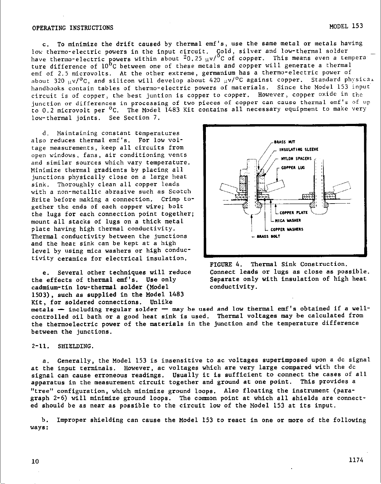
d. Maintaining constant temperatures
F?pf ~~5~%~~~~~~:~~~~~d~~~~~~~~ Es
and similar sources which vary temperature.
Minimize thermal gradients by-placing all
junctions physically close on a large heat
sink.
with a non-metallic abrasive such as Scotch
Brite before making a connection. Crimp to-
gether the ends of each copper wire; bolt
the lugs for each connection point together;
mount all stacks of lugs on a thick metal
plate having high thermal conductivity.
Thermal conductivity between the junctions
and the heat sink can be kept at a high
level by using mica washers or high conduc-
tivity ceramics for electrical insulation.
the effects of thermal emf's. Use only
cadmium-tin low-thermal solder (Model conductivity.
1503), such as supplied in the Model 1483
Kit, for soldered connections. Unlike
metals controlled oil bath or a good heat sink is used.
the thermoelectric power of the materials in the junction and the temperature difference
between the junctions.
Thoroughly clean all copper leads
Several other techniques will reduce
e.
including regular solder
FIGURE 4.
Thermal Sink Construction.
Connect leads or lugs as close as possible.
Separate only with insulation of high heat
- may be used and low thermal emf's obtained if a wellThermal voltages may be calculated from
2-11. SHIELDING.
Generally, the Model 153 is insensitive to ac voltages superimposed upon a dc signal
a.
at the input terminals.
signal can cause erroneous readings.
apparatus in the measurement circuit together and ground at one point.
However, ac voltages which are very large compared with the dc
Usually it is sufficient to connect the cases of all
This provides a
"tree" configuration, which minimize ground loops. Also floating the instrument (para-
graph 2-6) will minimize ground loops.
The connnon point at which all shields are connect-
ed should be as near as possible to the circuit low of the Model 153 at its input.
Improper shielding can cause the Model 153 to react in one or more of the following
b.
ways :
10
1174
Page 16

MODEL 153 OPERATING INSTRUCTIONS
Meter jitter or instability,
1.
High offset (dc bias).
2.
tion between the LO and GND Posts may affect the amount of offset.
3. Slow response time. sluggish action and/or inconsistent reading between ranges.
from 10% to 20% of full scale.
Reversing the power cord polarity or removing the connec-
c. To minimize pickup, keep the circuit away from ac sources.
possible.
The voltage induced due to a magnetic flux is proportional to the area of the loop.
fore, minimize loop areas in the shield connections as well as the input circuitry.
nect the shield at only one point. Run all wires in the circuit along the same path, so
the loop area is only the small difference in position of two adjacent rcires.
d. To reduce the effect of magnetic fields, use magnetic shielding. Where high ac magnetic fields are present, it may be necessary to magnetically shield the measuring circuit, the unknown emf circuit or auxiliary equipment in the circuit.
is available from several companies in the from of plates, foil or cable.
e. The Model 153 line frequency rejection refers to the total ac voltage appearing at
the input terminals. Therefore, in null detector applications,
of the ripple in the working standard and the unknown source.
standards having high ac ripple components will significantly reduce the amount of ac
voltage which may be tolerated in the unknown.
2-12.
a. When measuring in the microvolt region,
will have on the potential being measured.
significant, now become important.
of approximately 10 milliohms per foot.
of this wire will cause a voltage drop of five microvolts.
microvolt would mean using a wire an inch long.
Connect all shields together at the low side of the input or at the LO Post.
CIRCUIT CONNECTIONS.
consider the effect the physical connections
Voltage drops,
For example No. 20 AWG copper wire has a resistance
A 1-milliapere current through a 6-inch length
which in most circuits are in-
To reduce this drop below 1
Shield as carefully as
There con-
Magnetic shielding
it is affected by the sum
Because of this, working
Four-terminal ,,....,,:;,.., _.A.. “ZL,..
b.
be used to eliminate this error. Refer
to Figure 5.
If a small unwanted voltage drop is
c.
constant,
nullify the voltage.
d.
the measuring system fluctuate, they will
develop fluctuating voltages which will
appear as noise or drift in the system,
2-13. OPERATING FROM SOURCE OTHER THAN 117 VOLT.
use a screwdriver to change the 117-234 Switch on the back panel (Figure 3).
the fuse from 0.5 ampere to 0.25 ampere.
1174
the ZERO Control may be used to
If the currents or resistances in
FIGURE 5.
Connections,
If the ac power source is 234 volts,
No other adjustment is necessary.
Using Model 153 with 4-Terminal
Change
11
Page 17

APPLICATIONS
MODEL 153
SECTION 3.
3-l.
tims. These are
applications as demonstrations of techniques for using the Model 153.
3-2.
ful for measuring small signals from high source resistances.
can accurately measure a lo-millivolt signal through a l-megohm source.
The Model 153 is connected between the unknown and the potentiometer rather than across
the null detector terminals because shunts in the potentiometer reduce power sensitivity.
3-3.
wide range. For example,
drain current about 10-4
about 10-3 ampere.
lox voltage circuitry is undisturbed because the Model 153 has a very low input voltage drop
GESEFUL.
NULL DETECTOR.
The Model 153 is ideal for most null detector applications.
a.
Figure 6 shows a typical null circuit using the Leeds and Northrup K3 potentiometer.
b.
AMMETER. Solid-state circuit design often requires an ammeter with an extremely
This Section contains descriptions and diagrams of some Model 153 applica-
just
samples,
in the circuit of Figure 7, gate current is about lo-11
ampere, base current about 3 x 10⁻⁶
The Model 153 measures these currents easily and accurately.
and they do not exhaust all possible uses.
APPLICATIONS
ampere, and emitter current
Refer to these
It is particularly use-
For instance,
the Model 153
ampere,
The
FIGURE 6. Null Circuit Using Model 153 an
Leeds and Northrup K3 Potentiometer,
3-4. VOLTMEP.ER. Measuring microvolts
through megohm source resistance - a prime
requisite in semiconductor resistivity "easurements - is a simple task for the Model
153.
semiconductor resistivity measuring system.
Four sharp probes contact th? surface of a
semiconductor wafer or ingot.
rent is applied through the outer two probes,
while the inner two pick up the voltage
drop.
current,
probes.
12
Figure 8 illustrates a typical 4-point
Known cur-
Resistivity is then computed fro"
voltage drop and spacing between
FIGURE 7.
Solid State Circuits.
Diagram Showing Currents in
/
1
:GURE 8. Circuit Using Model 153 for
Semiconductor Resistivity Measurements.
I
1174
Page 18

MODEL 153
CIRCUIT DESCRIPTIOS
SECTION 4.
4-1. GE:;EF!AL.
The Keith1
a.
and demodulator
whole loop.
Signals below 1 volt are applied directly to the input filter; those above 1 volt
b.
arc attenuated 1OOO:l with a resistive divider.
input filter which attenuates undesireable ac signals.
4 cps.
feedback voltage.
the tuned ac amplifier,
nal is filtered and used to drive the output, meter and feedback.
=.
tor through which the input current flows.
range determines the current sensitivity.
The filtered dc signal enters the photo-modulator,
The Model 153 operates as an ammeter by measuring the voltage drop across a resis-
.ev Model 153 Microvolt-Ammeter consists of a photo-modulator, ac amplifier,
system followed by a dc cathode follower.
The difference or 'error signal is modulated at 4*3 cps, amplified by
and synchronously demodulated to regain dc.
Circuit designations refer to schematic diagram 1777111.
CIRCUIT DESCRIPTION
Feedback is applied to the
All signals pass through the low-pass
The filter has a 3 db cutoff at
where it is compared to the
The resistor used and the instrument voltage
NOTE
The demodulated sig-
4-2. INPUT CIRCUIT.
The setting of the FUNCTION Switch,
15::
put terminal, and the input resistance is approximately two megohms for all ranges.
ting the Switch to OPEN increases the input resistance of each range to that shown in Table
1.
by resistors R134 and R135.
resistance, but a synthetic resistance obtained by using high feedback factors.
tive divider, consisting of resistors R134 to R137.
ac signals from the voltage being measured.
and R104 and capacitors ClOl, Cl02 and ClO3.
I
With the Switch set to VOLTS INPUT R-2M, resistor R133 is connected to the high in-
For the 3-voit ano nq+nrr ranges,
For the lower ranges the input resistance is not a fixed
For the 3-volt and higher ranges,
b.
The input signal is then filtered by the low pass input filter to remove unwanted
=.
52, determines the input resistance of the Model
set-
~nr input r~rsistance is 200 megohms, as determined
the input signal is attenuated 1OOO:l by a resis-
The filter consists of resistors R102, R103
1174
FIGURE 9.
Model 153 Block Diagram.
Page 19

CIRCUIT DESCRIPTION
Resistor R102 and neon lamp GLlOl in the input circuit provide overload protection
d.
for lhe voltmeter.
The input also includes a system for increasing the speed of measurr-
MODEL 153 MCROVOLT-AMMETER
mats from high source impedances by driving capacitor Cl02 from the feedback signal.
The dc input signal is converted to an ac signal by photo-modulators El01 and ELO?.
c.
The
piloto-modulators are specially designed for high input resistance and low offset.
Lucite rods are used to conduct the light from lamps ElOlB and ElOZB to the cells to reduce the drive signal through them.
The input filter and photo-modulator are housed in a separate compartment to shield
f.
and insulate these circuits.
4-3.
AMPLIFIERS.
The ac signal from the photo-modulator is amplified by a 5-stage ac amplifier and
a.
demodulated to dc.
Tke ac amplifier uses low-noise design with fixed bias and low plate voltage on the
b.
first tk‘o amplifier stages, VlOlA and V102A.
The fourth amplifier stage uses a frequency
selective twin-T filter tuned to the carrier frequency to reduce noise and to reduce the
modulation products and beats associated with the modulating action.
Resistors R145 to
R153 are selected with the RANGE Switch and are used in the circuit to vary the amplifier
gain as the ranges are changed.
This maintains an approximately constant feedback factor
on all but the most sensitive ranges.
The output of the ac amplifier is applied to photo-modulator El03 and converted to
=.
The signal is filtered by capacitor Cl20 and resistors R126 and R128 to R130 to re-
dc.
duce the carrier signal appearing on the output.,
4-4.
CATHODE FOLLOWER.
V103B, an impedance transformer which provides a l-volt, l-milliampere output.
The filtered dc signal is applied to the cathode follower, tube
The output
also supplies the recorder output, meter and feedback network.
4-5. FEEDBACK NETWORK.
The feedback network, constructed of accurate stable resistors, controls the input
a.
sensitivity of the instrument.
Special precautions have been taken to keep any thermal
emf's generated to a minimum.
The feedback network is connected between the output of tube V103B and the photo-
b.
modulator, E102A. Setting the RANGE Switch, Sl, selects the feedback resistor, R131,
R158 and R164 to R173, used for the particular range.
4-6.
AMMI?J?ER OPERATION.
When the FUNCTION Switch is set to AMPS, one of resistors R138
to R144 is connected across the input. The particular resistor depends upon the range
being used.
The voltage drop across the resistor, which varies from 10 microvolts to 100
millivolts, is then measured by the Model 153, and read directly in amperes.
4-7.
MULTIVIBRATOR. The multivibrator is a twin-triode tube, V201; which use.8 highly
stable resistors and capacitors in the frequency determining circuits. Potentiometer
R210 adjusts the multivibrator frequency to exactly that of the frequency selective ampli-
fier. The multivibrator is used to drive the neon lamps in the photo-modulators.
.
Page 20

MODEL 153 MICROVOLT-AMMETER
1
CIRCUIT DESCRIPXOS
4-8.
POWER SUPPLY. The power supply uses a highly shielded transformer, Tl, to obtai?
good line isolation for floating operation. A separate winding with rectifiers supplies
a dc voltage for the first amplifier tube filament to reduce amplifier noise.
supply output is regulated by tubes V302 and V301 and zoner diode D305.
regulated outputs, t257,
+150 volts and -13 volts.
An unregulated -306 volts is also
There are three
The poxr
furnished to the multivibrator.
1174
15
Page 21

I
SERVICING
MODEL 153 MICROVOLT-AMMETER
1"str"me"t
<ewlett-Packard Model 200CD Oscillator,
j cps to 600
<eithley Instruments Model 241 Regulated
iigh Voltage Supply, 0 to 1000 volts.
10.05%
<eithley Instruments Model 260 Nanovolt
3ource,
to 1 volt, '0.25%
<eithley Instruments Model 261 Picoampere
Source,
ta 10-4 ampere, +0.25X
Keithley Instruments Model 370 Recorder
Keithley Instruments Model 6lOB Electro-
neter
Tektronix Type 504 Oscilloscope; dc to 450
5 mv/cm sensitivity
kc,
kc, ~2%
10-6 to 10-3 volt
10-11 to 10-7
ampere, f0.5"/.; 10-7
) ?0.5%, 10-3
Use
Low frequency rejection
Source for calibrating high voltage
t-a"geS
Source for calibrating low voltage ran.ses
Source for calibrating current ranges
Record stability
General circuit testing
Check wave forms
rektronix Type P6006 Probe; lo-megohm input impedance, 1O:l attenuation ratio
22-megohm shielded resistor
200~megohm shielded resistor
I ’
Divider:
coupling capacitor <Fib;;; 13).
;rid-modulated tube tester
TABLE 2.
instruments or their equivalent.
22 MR and 1 kR with 1000 pf, 15 v
Equipment Recommended for Model 153 Troubleshooting and Calibration.
Use with oscilloscope
Open circuit zero adjustment
Input impedance check
Multivibrator frequency adjustment
Test tubes
Use these
I
16
1174
Page 22

MODEL 153 MICROVOLT-AMMETER
SECTION 5. SERVICING
SERVICISC
5-l.
Model 153.
usefulness of the instrument.
5-2. SERVICING SCHEDULE.
mal care required of high-quality electronic equipment.
under ordinary use except the bias batteries or,
of the bias batteries is approximately two years.
5-3.
components in the Model 153. Replace components only as necessary; use only reliable replacements chich meet the specifications. Replace those items listed for Keithley manufacture (80164) only with components supplied by Keithley Instruments, Inc., or its representative.
5-4.
15;:
2 lists equipment recommended for troubleshooting.
cated or repaired, contact Keithley Instruments, Inc., or its representative.
placing tubes will clear up the difficulty. All tubes can be readily tested on a grid-
GENERAL. Section 5 contains tile maintenance and troubleshooting procedures for the
Follow these procedures as closely as possible to maintain the accuracy and
The Model 153 needs little periodic maintenance beyond the nor-
No part should need replacement
occasionally, a vacuum tube.
PARTS REPLACEMENT.
Tube VlOl is aged;
TROUBLESHOOTING.
Thz following procedures are for repairing troubles which might occur in the Model
Use these procedures to troubleshoot and use only specified replacement parts.
Before proceeding with the troubleshooting, check the vacuum tubes. Normally, re-
b.
The Replaceable Parts List in Section 8 describes the electrical
replace only with a Keithley part.
If the trouble cannot be readily lo-
The life
Table
Replaced Tube
VlOl
V102 and V201 slow or sluggish re-
v103
V301 and V302
TABLE 3.
above adjustments might be necessary.
Possible Adjustments for Replaced Tubes,. After a faulty tube is replaced, the
Check for
noise
meter accuracy
sponse on 10 and 30-pv adjustment
ranges
meter accuracy
correct bias
meter accuracy
correct bias
zero center meter
i3CCU?Z.?CY
Adjustment
replace tube
meter adjustment
multivibrator frequency 5-6
meter adjustment
bias adjustment 5-5
meter adjustment 6-3
bias adjustment 5-5
zero center meter adjust-
ment
Refer to paragraph 5-4.
Paragraph
Reference
,
6-3
6-3
6-3
1174
17
Page 23

I
SERVICING
MODEL 153 MICROVOLT-AMMETER
modulated tube tester for usual operation,
best way to test a tube.
procedures. Replacing tubes does not necessitate complete recalibration of the instrument.
Refer to Table 3 for adjustments which might be necessary.
Table 4 contains the more common troubles which might occur.
c.
cated in the Table do not clear up the trouble, make a point-by-point check of the circuits. Start by rechecking the power supply for proper operating voltages:
+150 volts,
within the power supply.
The schematic diagram 17771H, found in Section 8,
d.
points.
shorted.
Refer to the circuit description in Section 4 to find the more crucial components and to
determine their function in the circuit.
and -13 volts.
For these values,
The Model 153 controls are set:
METER Switch
FUNCTION Switch
RANGE Switch
If replacing a tube does not correct the trouble, continue the
Figures 10 to 12 show typical ripple at three test points
Use the Oscilloscope to obtain the patterns.
measured tiith the Model 6lOB to ilO%, the Model 153 input is
However,
substituting known good tubes is the
If the repairs indi-
+275 volts,
contains the voltages at selected
+
VOLTS R-2M
1 VOLT
FIGURE 10. Wave Form at Junction of Diodes
D301 and D302 (Figure 27). Vertical setting
is 1 volt/cm; horizontal, 2 milliseconds/cm.
Output is approximately t4UU volts dc.
5-5.
ground by connecting point T. P. (Figure 21) to ground.
the METER Switch to f; and the FUNCTION Switch to INPDT R-2M.
tiometer, R125 (Figure 20), for a zero meter reading.
ground;
5-6.
BIAS ADJUSTMENT. Check the mechanical meter zero. Short pin 1 of tube V103 to
adjust for exact meter zero.
MULTIVIBRATOR FREQUENCY ADJUSTMENT.
Remove tubes VlOl and V103 (Figure 21).
a.
FIGURE 11. Wave Form at Junction of Resistor R302 (Figure 27) and Capacitor C302B
(Figure 19).
volts/cm; horizontal, 2 milliseconds/cm.
Output is approximately +12 volts dc.
FIGURE 12 (Left). Wave Form at -13 Volt
SUPPlY.
horizontal, 5 milliseconds/cm.
Turn the METER Switch to + and the FUNCTION
Vertical setting is 20 millivolts/cm;
Set the RANGE Switch to 1 VOLT;
Remove the short between T. P. and
Vertical setting is 5 milli-
Adjust the BIAS ADJ Poten-
18
1174
Page 24

MODEL 153 MICROVOLT-AMMETER
Difficulty Probable Cause Solution
SERVICING
Instrument inaccurate on
all ranges
Instrument inaccurate on ATTENUATOR Potentiometer R137
3-volt and higher ranges
Excessive zero drift Input filter capacitors polar-
METER CAL Potentiometer R176
out of adjustment
out of adjustment
ized from excessive overload
Battery BlOl or B102 faulty
Adjust per paragraph 6-
Adjust per paragraph 6-.
Let sit for a few hours
on 3 to
lOO-mv range
Check; replace if fault!
VlOl, v102 or v103 faulty Check; replace if fault]
Check; replace if fault!
Slow or sluggish response
on all ranges
Diode D103 faulty
MULTIVIBRATOR Potentiometer Adjust per paragraph 5-t
R210 out of adjustment
Excessive zero drift and MIJLTIVIBPATOR Potentiometer Adjust per paragraph 5-c
slow sluggish response
Excessive noise on most
R210 out of adjustment
Battery BlOl or Bl02 faulty
Check; replace if fault)
sensitive voltage ranges
Excessive overload damaged Check; replace if fault)
resistor R102
Tube VlOl or V103 faulty Check; replace if faulty
Diode D103 faulty Check; replace if faulty
Constant offset on all ran- Meter mechanical zero out of Set METER Switch to POWE
ges with input s:i;zt;?
..lI....c--^rC
- - _) - _ _.- _ . . BIAS Potentiometer R125 out of
OFF; edjust
Adjust per paragraph 5-5
adjustment
%eter off zero on zero ZERO CENTER Potentiometer R177 Adjust per paragraph 6-3
:enter scale out of adjustment
Zero shift with changing OPEN CIRCUIT ZERO Potentiometer Adjust per paragraph 6-5
source resistance on more R160 out of adjustment
sensitive ranges
%cessive ac line frequency
interference
Large ac fields present Change location or im-
prove shielding
Battery BlOl faulty Check; replace if faulty
Heater-to-cathode leakage in Check; replace if tube
VIOI, vm.? or VI03
is faulty
1174
TABLE 4.
Excessive power supply ripple
Model
153 Troubleshooting Chart.
Check per paragraph 5-4
19
Page 25

SERVICING
MODEL 153 MICROVOLT-AMMETER
FIGURE 13.
brator Frequency Adustment.
Divider Connection for Multivi-
Connect the
divider to either pin 1 or 6 of V201 and to
pin 2 of V102A. Use l%, l/2 watt, deposi-
FIGURE 14.
put.
Oscilloscope was attached to pin 1 of
tube V201A (Figure 19). Vertical setting
is 100 volts/cm; horizontal, 5 msecicm.
Wave Form of Multivibrator Out-
ted carbon resistors and a 15-volt capacitor for the divider.
SWITCH to INPUT R-2M.
Use the Model 610B to check pin 7 of tube VlOl for approximately
-1.23 volts +lO%.
Place the resistor divider from either plate of tube V201 (Figure 19) to ground.
b.
See Figure 13. Connect the output of the divider to the grid of tube V102A (Figure 21).
Monitor the output across resistor R121 (Figure 22) with the Type P6006 Probe.
C. Set the RANGE Switch to 30 MILLIVOLTS.
Adjust the MULTIVIBRATOR FREQUENCY ADJ Poten-
tiometer, R210 (Figure 27), to obtain the largest signal across resistor Rl21, approxi-
mately 6.5 to 7.5 volts peak-to-peak (650 to 750 millivolts with divider Probe).
14 shows typical wave form at the multivibrator output.
across R121 (junction of R121 and C117).
signal to swing through maximum,
change the value of resistor R208 (Figure 27) to center
If tuning potentiometer R210 does not cause the
Figure 15 shows typical waveform
Figure
the potentiometer adjustment.
FIGURE 15. Wave
tor Output
Across Resistor R1.21 (Figure 22).
Form
for Tuned Multivibra-
Vertical setting is 1 volt/cm; horizontal,
2 milliseconds/cm.
FIGURE 16.
ElOl.
Wave
The output is monitored at pin 2 of
VlOl with a 1O:l divider probe. Oscillo-
scope IS dc coupled.
20 millivolts/cm; horizontal, 2 milliseconds/cm.
Form for Input Modulator
Vertical setting is
20 1174
Page 26

MODEL 153 MICROVOLT-AMMETER SERVICING
TUtJc Gain
VlOlA 10
VlOlB 10
V102A 20-30
V102B 25-35
FIGURE
Demodulator Wave Form for Full-
17.
Scale Input on l-Volt Range. The signal is
V103A 30-35
monitored at the junctions of capacitor
C113, resistor R126 and modulator E103A.
TABLE 5. Approximate Amplifier Gains by
stages.
5-7.
network to ground; see paragraph 5-8b.
INPUT MODULATOR CHECK.
Remove the divider of Figure 13; remove tube VlOl (Figure 21).
a.
Set the RANGE Switch to 1 VOLT. Use the
Model 260 Nanovolt Source to apply a +l volt input signal to the Model 153.
Vertical setting is 2 volts/cm; horizontal,
2 milliseconds/cm.
Short the feedback
Use the Type
P6006 Probe with the Oscilloscope to monitor the signal at pin 2 of tube VlOl (Figure 21).
A typical wave form is show" in Figure 16 for a properly functioning modulator El01 (Fig-
ure
23).
The wave should be a minimum of
700
millivolts
peak-to-peak average value (70
millivolts using the 1O:l Probe).
Replace all tubes and shields; allow the instrument to stabilize for
b.
5-8.
amplifier gain for each range.
and the constant _oain f~rrnrr IV-P ohz=cbc=cl
GAIN ADJUSTMENT.
a. The
Model 153
maintains a" approximately co"Uta"t feedback factor by changing the
In the gain adjustment,
the feedback network is shorted
a
few
minutes.
Short the feedback network on the Model 153 by connecting the rear,deck of the
b.
RANGE Switch, Sl (Figure 19),
to the circuit low terminal of the INPUT Receptacle.
Set
the METER Switch to +, the EIJNCTION Switch to OPEN, and the RANGE Switch to 30 MILLIVOLTS.
Apply a" input signal to the Model 153, using the Model 260, sufficient to obtain a full-
scale meter reading; normally this will be between 300 and 400 microvolts. Set the METER
Switch to - and repeat this procedure.
essary to drive the meter to full scale.
Average the value,of the two input voltages "ec-
If the average is between 300 and 430 microvolts,
the loop gain of the Model 153 amplifier is between 100 and 70. If the average is less
than 300 microvolts, add resistor, RllO (Figure 22), to decrease the gain. If the average
is greater than 430 microvolts, the gain is too low.
If the gain is too low,
c.
either the efficiency of modulator El01 (Figure 23) is too
low or the gain of a particular amplifier stage is too low. Normally, the modulator ef-
fiency should be greater than 70%.
on the l-volt range is shown in Figure 17.
5-9. NOISE.
Set the Model 153 RANGE Switch to 10 MICROVOLTS and short its input. Meter
noise must be less than 3 minor divisions,
Switch to AMPS. Shield the input and check meter noise.
For a l-volt input signal, the demodulator wave form
Typical stage gains are show in Table 5.
exclusive of any thermal drift. Set the FUNCTION
It should be less than 5 minor
divisions, exclusive of any thermal drift.
1174
21
Page 27

SERVICING
5-10. AC REJECTION CHECK.
MODEL 153 MICROVOLT-AMMETER
60-cps Rejection:
a.
Operate the Model 153 from a 60-cps power line.
tor to apply a lo-volt peak-to-peak,
60-cps signal to the Model 153 input. Set the Model
Use the Oscilla-
153 RANGE Switch to 100 MILLIVOLTS, and the METER Switch to ZERO CENTER. Turn down the
Oscillator output amplitude and make sure the Model 153 is properly zeroed.
There should
be less than 0.5% change in the meter needle deflection from no signal to full signal.
Disregard any transient swings while applying the signal.
50-cps Reiection:
b.
Operate the Model 153 from a 50-cps power line.
Follow the in-
structions given for the 60-cps rejection check in the preceding sub-paragraph.
22
1174
Page 28

I
MODEL 153 MICROVOLT-AMMETER
CALIBRATION
SECTldN 6. CALIBRATION
6-1. GENERAL,
The following procedures are recommended for calibrating the Model 153.
a.
equipment recommended in Table 2.
If proper facilities are not available or if difficulty
is encountered, contact Keithley Instruments, Inc.,
factory calibration.
or its representative to arrange for
Use the
The following procedures are covered:
b.
meter and attenuator adjustments, open circuit zero adjustment, verification of voltage and current range calibrations, rise time and
drift verifications, and input impedance check.
If the Model 153 is not within specifications after the calibration, follow the
c.
troubleshooting procedures or contact Keithley Instruments,
6-2. CALIBRATION SCHEDULE.
Calibrate the Model 153 yearly.
Inc., or its representative.
This normally means perfor-
ming the bias adjustment (paragraph 5-5), meter adjustment (paragraph 6-3), attenuator
adjustment (paragraph 6-4), and open-circuit zero adjustment (paragraph 6-5). The other
verifications need be done only if desired.
6-3.
If necessary, adjust the BIAS ADJ Potentiometer, R125 (Figure 20).
METER ADJLISTMENIY.
a. After a 30-minute warm-up,
check the Model 153 for zero reading on the l-volt range.
See paragraph 5-5.
Connect the Model 260 Nanovolt Source to the Model 153 INPUT Receptacle. Set the
b.
controls as follows:
METER Switch
FlTNC’?TCIN !-hi trh,
RANGE Switch
+
INPUI R-2M
1 VOLT
Control
Bias adjust
Circuit
Desig.
R125
Fig.
Ref.
20
Refer to
Paragraph
Attenuator adjust R137 20 6-4
Open circuit Zero R160 20 6-5
Meter Calibration R176 20 6-3
Center Zero adjust
Multi-vibrator frequency adjust
TABLE 6.
Model 153 Internal ,Controls.
R177 20 6-3
R210 27
The Table lists all internal controls, the figure
picturing the location and the paragraph describing the adjustment.
5-5
5-6
l
Page 29

CALIBRATION
MODEL 153 MICROVOLT-AMMETER
Set the Model 260 to apply +l volt.
20.5%.
scale deflection. This adjusts the meter for all voltage ranges below 1 volt.
c.
Control on the rear panel for a l-volt output il%.
d.
METER Switch to CENTER ZERO; keep the FUNCTION and RANGE Switches as in sub-paragraph b.
The meter needle should be at zero on the bottom scale.
ZERO ADJ Potentiometer, R177 (Figure 20) for zero meter deflection on the bottom scale.
6-4. ATTENUATOR ADJUSTMENT.
Receptacle.
Set the Model 241 to apply +lO volts.
iO.S%.
full-scale deflection.
If necessary, adjust the METER CAL Potentiometer, R176 (Figure 20), for a full-
Using the same settings and input as in the previous step, adjust the OUTPUT ADJ
Remove the input signal from the Model 153 and short the input terminals.
Connect the Model 241 Voltage Supply to the Model 153 INPUT
Set the Model 153 controls as follows:
METER Switch
FUNCTION Switch
RANGE Switch
If necessary, adjust the ATTENUATOR ADJ Potentiometer, R137 (Figure 20), for a
This adjusts the meter for all voltage ranges 3 volts and higher.
The Model 153 meter should read full scale, 1 volt
Set the
If necessary, adjust the CENTER
+
INPUT R-2M
10 VOLTS
The Model 153 should read full scale, 10 volts
NOTE
Before making this adjustment, warm up the Model 153 for at least two hours and
make sure its drift is within specifications (paragraph 6-9.)
6-5.
Shunt the input with a 22-megohm shielded resistor between the high (center terminal) and
low (inner shield) of the INPUT Receptacle.
meter using the front panel ZERO Control.
the OPEN CIRCUIT ZERO Potentiometer, R160 (Figure 20), for a zero meter reading.
the FUNCTION Switch to AMPS position and recheck for meter zero.
6-6. VERIFICATION OF VOLTAGE CALIBRATION.
positive and negative polarity. Calibrate the lo-microvolt to l-volt ranges before
calibrating the higher ranges. Make sura potentiometer R125 is adjusted (paragraph 5-5).
input.
put signal for the lo-microvolt range; 30-microvolt input signal for the 30-microvolt
range, etc.),
for the lOO-microvolt to l-millivolt ranges, within -f1.5%; for the 3-millivolt to l-volt
ranges, within -fO.5%.
Check for both positive and negative polarity.
tiometer, R176 (Figure 20), until all ranges meet specifications.
adjusted for any subsequent range, repeat the calibration for each previous range until
all ranges,are within the required accuracy.
OPEN CIRCUIT ZERO ADJUSTMENT.
Calibrate the voltage ranges for a full-scale meter deflection on all ranges, both
a.
For the ranges from 10 microvolts to 1 volt, connect the Model 260 to the Model 153
b.
For each range,
For the 10 and 30-microvolt ranges, the Model 153 should read within +2.5%;
set the Model 260 for a full-scale input (i. e., lo-microvolt in-
On the zero-left scale, 1% is equivalent to one minor division.
Set the Model 153 RANGE Switch to 30 MICROVOLTS.
Set the FUNCTION Switch to AMPS; zero the
Switch the FUNCTION Switch to OPEN and adjust
Return
If necessary, adjust the METER CAL Poten-
If the potentiometer is
For the ranges from 3 to 1000 volts,
c.
Model 153 input.
24
For each range,
connect the Model 241 Voltage Supply KO the
set the Model 241 for a full-scale input.
For all these
1174 ;
Page 30

I
MODEL 153 MICROVOLT-AMMETER
CALIBRATIO::
<~
ranges, the Model 153 should read within 10.5% of full scale.
negative polarity.
for the proper range accuracy. If potentiometer Rl37 is adjusted for any range, repent
the calibration for each range from 3 to 1000 volts until all ranges arc within the req_lred accuracy.
6-7. VERIFICATION OF CURRENT RANGE CALIBRATION.
Connect the Model 261 Picoampere Source to the Model 153.
a.
Model 261 for a full-scale input.
ampere to 100~milliampere ranges;
and i3.5% for the 30 and lo-picoampere ranges.
current source; the Model 261 output is not sufficient for the higher ranges.
The range resistor in the 3 through 100-milliampere positions, Rl44, is selected t3
b.
0
a +a/.,
sistor to circuit low.
6-8. RISE TIME VERIFICATION.
a. Connect the Oscilloscope to the Model 153 OUTPUT,
Model 260 POLARITY Switch from OFF to + or - as required) to the Model 153 input which
will produce 100, 30 or lo-microvolt full-scale readings. The rise time (10% to 90% of
full scale) for a full-scale input signal should be less than 1 second on the loo-micro-
volt range; less than 5 seconds on the 30 and lo-microvolt ranges.
-2% tolerance due to a" approximate 1% effect in the lead resistance from the ri--
If necessary, adjust the ATTENUATOR ADJ Potentiometer, R137 (Figure Xl),
The Model 153 should read within f1.5% for the 3 "an=-
?2.5% for the 1-nanoampere to lOO-picoampere ranges;
For the ranges above 10-4, construct a
Use a step function (turn the
Check for both positive 2nd
For each range, set tht
Apply the step function for the l-millivolt and higher ranges. Note the motion oi
b.
the meter.
tor R127 (Figure 22) to obtain a smooth motion.
6-9. DRIFT VERIFICATION.
with a good low thermal short.
METER Switch to +.
8 microvolts. After two hours,
See Figure 18 for a typical drift run for the Model 153.
6-10. INPW IMPEDANCE CHECK.
153 input.
Apply 1 volt to the resistor with the Model 241 Voltage Supply. The Model 153 must read
at least 50% of full scale.
FIGURE 18.
range at various increasing input shunt resistances between short circuit and 20 megohms.
Noise increases with increase in shunt resistance as Johnson noise' in the shunt add in
quadratare to basic instrument noise.
due to physical changing of the shunts.
If the meter shows uneven travel to full scale, increase the value of resis-
Make sure the Model 153 cover is on and the input is shorted
Connect the Model 153 to the Model 370 Recorder. Turn the
During the first two hours of warm-up, the drift should be less than
the drift should be within f2 microvolts per 24 hours.
Put a 200-megohm shielded resistor in series with the Model
Set the Model 153 RANGE Switch to 1 VOLTS and the FUNCTION Switch to OPEN.
If it does not,
Typical Model 153 Drift Chart.
Transients occuring at points of shunt change are
return the instrument to the factory.
The instrument is set on the
lo-microvolt
I
1174
25
Page 31

CALIBRATION
MODEL 153 MICROVOLT-AMMETER
FIGURE 19.
meter feting left.
26
Model 153 Interior.
Components and assemblies are shown in the view with the
Figure 20 shows the chassis view from the other side.
1174 :
Page 32

I
l-
MODEL 153 MICROVOLT-AMMETER
CALIBRATION
(Fig. 27:
,301
..,,_ ;.A::~
FIGURE 20. Model 153 Interior.
meter facing right.
I
1174
Figure 19 shows the chassis view from the other side.
Components and assemblies are shown in the view with tt
.&A>~~~_. _
.
.“L..~. -. _~
27
Page 33

CALIBRATION
MODEL 153 MICROVOLT-AMMETER
"lOl--;i
--"d.- ..,. -
FIGURE 21.
Capacitor, Tube,
Battery and Modulator Locations on Printed Circuit
Board PC106. Refer to Figure 22 for resistor locations.
28
r
1174 _
Page 34

Page 35

CALIBRATION
MODEL 153 MICROVOLT-AMMETm
cio3
cio4
FIGURE 23 (left).
Component Locations f3r
Printed Circuit Board PClO7.
FIGURE 24 (right).
Component Locations
on Model 153 Rear Chassis Panel.
is from the inside of the instrument.
The view
P
30
Page 36

I
MODEL 153 MICROVOLT-AMMETER
CALIBRATION
I
I
FIGURE 25.
Switch Sl.
1174
Component Locations on Range
R169-
FIGURE 26.
Switch Sl.
IRi66 1
R167 Rl65
Component Locations on Range
RI-64
31
Page 37

I
CALIBRATION
i<rzOV-
3.201-
w ..-
MODEL 153 MICROVOLT-AMMETER
R207'
RZO?-
C303
FIGURE 27.
'1 r,
.i
Y
Component Locations for Model 153 Power Supply and Multivibrator.
I
32
1174
Page 38

MODEL 153 MICROVOLT-AMMFPER
ACCESSORIES
SECTION 7.
7-l.
3-foot triaxial cable,
feature is useful for attaching the Probe at a single point for repeated measurements.
When making low-level measurements,
thermal emf's.
measurements.
Keithley part number for the input cable used on the Probe is SC-22; the number for the
cable on the low lead is SC-32.
7-2.
153 is with the Model 1532 Test Leads supplied with the instrument. The Leads consist
of a mating connector to the Model 153,
designed for repeated measurements. To reduce thermal emf's, the Leads are of all copper
construction and use low-thermal cadmium solder connections.
remnve the alligator clips and attach the lead to a circuit with low-thermal solder (Model
1503) or by a crimp connection.
as Scotch Brite, before making the connecl
MODEL 1531 GRIPPING PROBE (Figure 28).
It is useful for making in-circuit measurements.
Allow the circuit being tested to reach thermal equilibrium before ;n;i.ng
Connect the Probe plug directly to the Model 153 INPLlT Receptacle.
MODEL 1532 TEST LEADS (Figure 29).
Clean the bare wire with a non-metallic abrasive, such
The plug on the Leads mates with th,
:t.
handle the probe body as little as possible to avoid
ACCESSORIES
The Model 1531 has a gripping probe and e
Its gripping
An easy way to make connections to the Model
a 3-foot cable and two alligator clips. It is
For permanent connections,
:iol
eM
For trim" connections. use the Model 1483
1.
od
153 INPirr Receptacle: ,
I.
FIGURE 28.
Gripping Probe.
7-3.
30).
with the Model 153 special triaxial INPUT
Receptacle and to accept the Model 1534
Triax Cable or any other cable with 0.145-
inch outer diameter. FIGURE 30.
7-4,
CABLE.
ciently high to maintain the Model 153's performance specifications.
is 1000 volts center conductor to inner shield; 500 volts between shields. The Cable uses
copper in the signal leads.
with no connectors.
7-5.
used is clean and that it has not been used with regular solder before.
MODEL 1533 MATING CONNECTOR (Figure
The Model 1533 is designed to mate
MODEL 1534 SPECIAL LOW-THERMAL TRIAK
ACCESSORY KITS.
If cadmium solder (Model 1503) is used for a connection,
a.
Keithley Instruments Model 1531
The Model 1534 is 10 feet of low-noise cable which has leakage resistance suffi-
outer diameter of the Cable is 0.145 inch.
FIGURE 29.
T.DL Laida.
I
I
Mating connector.
KeFthley Instruments Model 1532
Keithley Instruments Model 1533
Voltage breakdown
The Cable comes
make sure the soldering iron
Use only rosin
1
I
Page 39

ACCESSORIES
.-..-- ^. . .I”^_ -. .^
LG”Kb JL.
Ploae1 lita, LOw-‘l”ermaL Lonnec-
tion Kit. Refer to Section 8 for contents.
MODEL 153 MICROVOLT-AMMETER
b. Use crimp connections vith copper
wire and lugs ior the best low-thermal
joints. Thcrzml enf's can be reduced to
10 nanovolts or less using the copper vi:_:
sleeves and lugs found in the Model 1483
Loxr-Thermal Connection Kit.
'Tllc Kit con-
tains a crimp tool, shielded cable, an assortment of copper lugs, copper wire, cai-
mium solder and nylon bolts and nuts.
is a complete kit
for making very low the:-
1:
ma1 measuring circuits. The Kit enables
the user of the Model 153 to maintain ther-
mal stability in his own circuit. Sectio::
8 lists the contents of the Kit.
7-6. MODEL 6012 ADAPTER (Figure 32). The
Model 6012 is a triaxial-to-coaxial adapter.
FIGURE 32.
Keithley Instruments Model 6012
Triaxial-to-Coaxial Adapter
floated when used with the Adapter.
Circuit low and chassis ground are connected, and the
It may be used to connect uhf and coaxial
circuits to the Model 153 input. Note, j‘3>1ever,
that the Model 153 should not be
outer shell of the Adapter would be off ground if it were floated.
7-7. RACK MOUNTING (See Figure 33).
The Model 153 is shipped for bench use.
a.
the instrunxnr tz ;mL's u,uu,,L;~I~ w LWZ
To convert the Model 153, remove the four screws at the bottom of each side of the
b.
sctinaard h.LA
The Model 4005 Rack Mounting Kit converts
LV-inch width.
instrument case. Lift off the top cover assembly with the handles; save the four screws.
To remove the feet and tilt bail from the bottom cover assembly,
remove the four screws
and allow it to drop off. Remove the feet and tilt bail and replace the bottom cover using
the same screws.
Item Keithley
(See Fig. 33) Description Part No. Quantity
1
2
3 Filler Panel
-_
__
Cover Assembly
20018B
1
Mounting Panel 19396B 1
19397B 1
Screw, No. IO-3/8, HSS
Kep Nut, No. 10
_-
--
12
8
TABLE 7. Parts List for Keithley Model 4005 Rack Mounting Kit.
34
1174 1
Page 40

MODEL 153~MICFiOVOLT-AMMETER ACCESSORIES
Insert the top cover assembly (1) in place and fasten to the chassis with the fo-r
c.
screws previously removed.
and kep nuts.
the filler panel (3) to the opening in the mounting panel with four #IO screws and
nuts.
0
Fasten the
3
I
0
Attach the mounting panel (2) to the rack with four /ilO sc:+:,:s
Model 153 to the mounting panel with four 810 screws.
Faster
kep
0
0
Q
1174
35
Page 41

Page 42

MODEL 153 MICROVOLT-MER
REPLACEABLE PARIS
SECTION 8.
8-I.
Model 153 and its accessories.
tion,
ber.
8-2.
Part Number,
and those parts coded for Keithley manufacture (80164) must be ordered through Krithle,~
Instruments or its representatives.
Parts List,
ment, Keithley Instruments, Inc.
=w
CbVar
CerD
Comp
CompV
REPLACEABLE PARTS LIST.
a suggested manufacturer, the manufacturer’s part number and the Keithley Part NIX-
The last column indicates the figure picturing the part.
HOW TO ORDER PARTS.
For parts orders, include the instrument’s model and serial number, the Keithle!
a.
the circuit designation and a description of the part.
completely describe the part, its function and its location.
Order parts through your nearest Keithley representative or the Sales Service Depart-
b.
a”pere Mfg.
Carbon Variable Mil No. Military Type Number
Ceramic, Disc
Composition
Composition Variable
The Replaceable Parts List describes the components of t?e
The List gives the circuit designation, the part descrip-
REPLACEABLE PARTS
All structural par-s
In ordering a part not listed in the Replaceable
Manufacturer
MtF Metal Film
MY
n
Mylar
ohm
DCb
EAl
JiUC
EXB
RTT
f
Fig.
hy
k
M or meg mega (106) or megohms wwvar
m milli (10-3)
Deposited Carbon
Electrolytic, Aluminum
Elecrrnlytir~ metal rza9eli
Electrolytic, tubular Ref.
Electrolytic, tantulum
farad
Figure
henry
kilo (103)
TABLE 8.
Abbreviations and Symbols
PMT Metalized paper, phenolic cas
Poly Polystyrene
P
CI
” volt
Var
Gw
wwenc
pica (lo-129
Reference
micro ( 10e6)
Variable
watt
Wirewound
Wirewound encapsulated
Wirewound Variable
,
.
1174
37
Page 43

RE LACEABLE PARTS
P
MODEL 153 MICROVOLT-AMMETER
J.lODEL 153 REPLACEABLE PARTS LIST
(Refer to Schematic Diagram 17771H for circuit designations.)
CAPACITORS
Circuit Mfg.
Desig.
Cl01 0.1 pf
Cl02
Cl03 0.1 pf 100 v
Cl04 .Ol @f
Cl05 .OOl pf 1000 "
Cl06
Cl07 40/40/20 vf
Cl08
Cl09
Cl10
Cl11
Cl12 0.1 pf
Cl13
Cl14
Cl15
Cl16
Cl17 .Ol pf 300 "
Cl18
Cl19 100 pf
Cl20
Value Rating
100 ”
0.1 I.lf
.Ol IJ.f
.047 pf
10 pf
0.1 I.lf
.Ol kf
10 IJ.f
.05 pf
.05 pf 100 v
.l !Jf
0.5 wf
1.0 pf
100 v
500 "
200 v
450/450/50 " Em
200 v
15 v
200 v
1000 v
100 "
15 v
100 "
200 "
400 "
25 v
200 "
'Op=
Poly
Poly
Poly
Poly
CerD
MY
MY
EAl
MY
CerD
MY
EAl
MY
MY
MY
CerT 13050
MY
EAl
MY
Code
80164 C142-O.lM
80164 Cl42-O.lM
80164 Cl42-O.lM
71590
72982 8OlZ5V102P C22-.OOlM
14655
56289
14655
56289
02777
72982
12673
56289
12673
12673
02777
14655
29309
13050
Mfg.
Part No.
CPR-1000.J
WMF-2Sl
TVL3786
WMF-2547
8913159 C93-10M
P-12M C66-O.lM
811Z5V103P C22-.OlM
37-M
89D159
32M
32M
P-12.M
MWlA.Ol@
wMF4P5
JC8100258P C211-100M
107-21
Keithley Fig.
Part No. Ref.
Cl38-.OlM
C66-.OlM
C33-40/40/20M
C66-.047M
Cl05-O.lM
C93-10M
C105-.05M
C105-.05M
C66-O.lM
C61-.OlM
Cl14-0.5M
C66-l.OM
23
23
23
23
21
21 -
19
21
21
21
21
21
21
21
21
21
21
21
21
21
Cl21
Cl22 .05 vf 600 v
c201
c202
c301
C302
c303
c304
c305
circuit
Desig.
D301
D302
D303
100 !Jf '
.Ol pf
.Ol pf
80/40 pf
1000/1000 pf
100 )lf
.OOl pf
.OOl pf
VP=
Silicon
Silicon
Silicon
15 "
400 "
400 "
450/450 v
35 v
15 "
1000 v
1000 v
ETB
My
MY
MY
EMC
aB
ETB
CerD
CerD
Number
lN3256
lN3256
lN3253
DIODES
56289
56289
14655
14655 wMp4Sl
56289
56289
56289
72982
72982
Mfg.
- .
Code
02735 RF-22
02735 W-22
02735 ,xF-20
TE1162
6PS-S50
wMF4Sl
2778
FP =-'ti+/
TE1162
8OlZ5V102P C22-.OOlM
8OlZ5VlO2P C22-.OOlM
Keithley
Part No.
C3-100M
C62-.05M
c114-.olM 27
C114-.OlM
C36-80/40M
r
1' 27
: 27
21
24
27
20
19
27
24
24
Fig.
Ref.
27
38
1174
Page 44
MODEL 153.MICROVOLT-AMMFER
REPLACEABLE PARTS
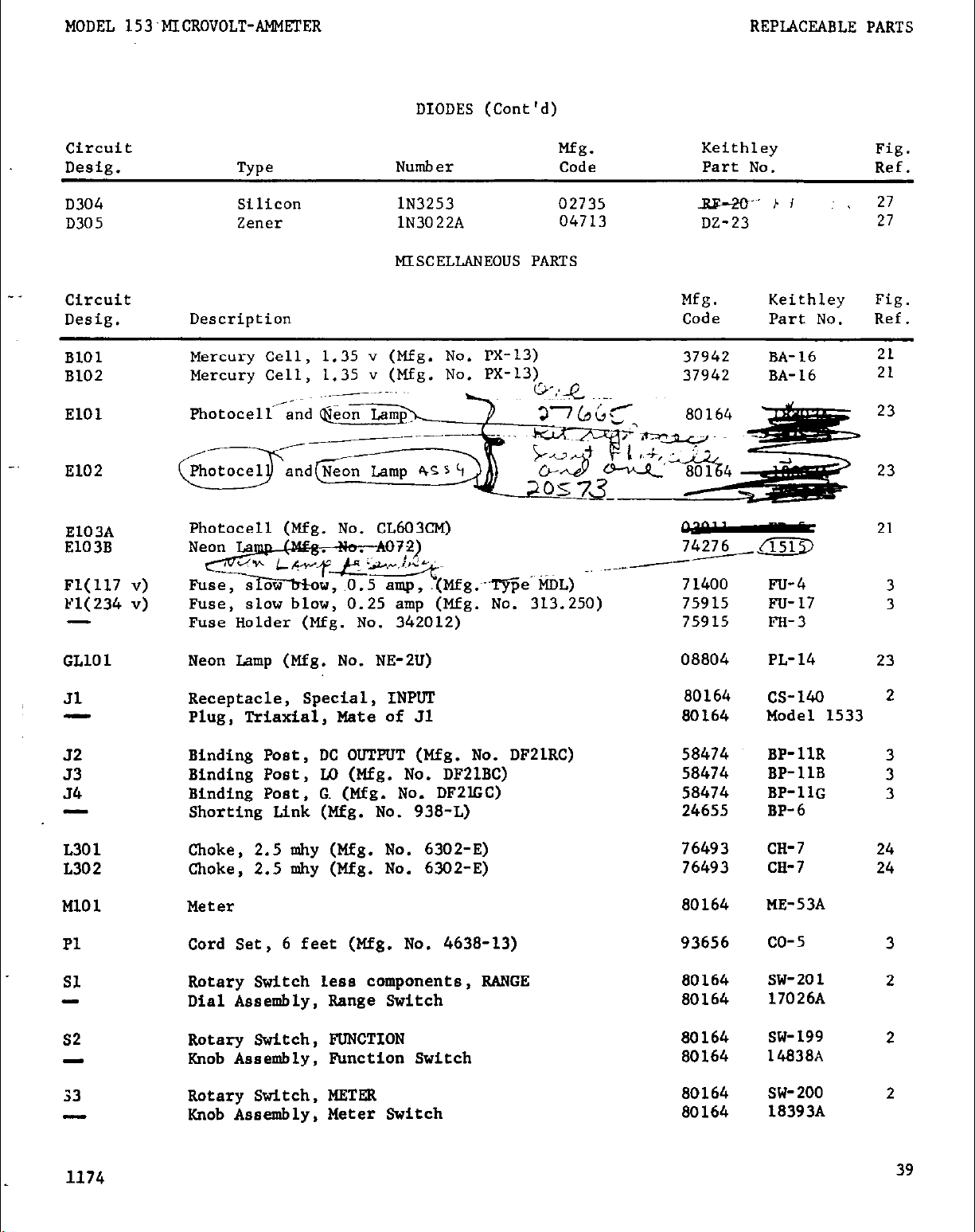
DIODES (Cont'd)
circuit
Desig.
D304
D305
Circuit
Desig.
BlOl
B102
El01
El02
E103A
E103B
Fl(117 v)
Yl(234 v)
-
Type
Silicon
ZlXC??2
Description
Mercury Cell,
Mercury Cell,
Photocell (Mfg. No. cL603C~)
Fuse;
Fuse Holder (Mfg. No. 342012)
slow blow, 0.25 amp (Mfg. Nb: 313.250)
1.35 v (Mfg. No. PX-13)
1.35 v (Mfg. No. PX-13).
NWlbel- Code
lN3253
lN3022A
MISCELLANEOUS PARTS
,mo c+ss
. . . -
Mfg.
02735
04713
Keithley
Part No.
Bs-20. b I
DZ-23
Mfg. Keithley
Code
37942 BA-16
37942 BA-16
75915
75915
Part No.
Fu-4
Fu-17
FH-3
Fig.
Ref.
~ 27
27
Fig.
Ref.
21
21
23
23
3
3
GLlOl
Jl
-
32
53
54
L301
L302
Ml01
Pl
Sl
52
33
Neon Lamp (Mfg. No. NE-2U) 08804
Receptacle, Special, INPUT
Plug, Triaxial, Mate of Jl
Binding Post, DC OUTPUT (Mfg. No. DFZlRC) 50474 BP-11R
Binding Post, LO (Mfg. No. DF2LBC) 58474 BP-11B
Binding Post, G (Mfg. No. DF2lGC)
Shorting Link (Mfg. No. 938-L) 24655 BP-6
Choke, 2.5 mhy (Mfg. No. 6302-E) 76493
Choke, 2.5 n&y (Mfg. NO. 6302-E) 76493
Meter
Cord Set, 6 feet (Mfg. No. 4638-13) 93656
Rotary Switch less components, RANGE 80164
Dial Assembly, Range Switch
Rotary Switch, FUNCTION
Knob Assembly, Function Switch
Rotary Switch, METER
Knob Assembly, Meter Switch
80164
80164
50474
80164
80164
80164
80164
80164
80164
PL-14
cs-140
Model 1533
BP-1lG
CH-7
m-7
ME-53A
co-5
SW-201
17026A
SW- 199
14a38A
SW-200
18393A
23
2
3
3
3
24
24
3
2
2
2
1174
39
Page 45

I
REPLACEABLE PARTS
MODEL 153 MICROVOLT-AMMETER
MISCELLANEOUS PARTS (Cont'd)
Circuit
Desig. Description
-
54
Tl
Knob, Zero Control
Slide Switch, 117-234 v
Transformer
Circuit
Desig.
RlOl
R102
R103
R104
R105
R106
R107
R108
R109
RllO
Value Rating
109 I?
270 kn
270 kn
270 kn
1 kn
6.5 WI
2.2 lm
1m
500 !a
"330 krl
20%, l/2 w
lO%, l/2 w
lO%, l/2 w
lO%, l/2 w
lO%, l/2 w
l%, l/2 w
l%,
l/2 w
l%, 1 w
l%,
l/2 w
10%, l/4 w
RESISTORS
Mfg.
TYPO
Comp
Comp
Comp
Comp
Comp
DCb
DCb
Code Part No.
75042
01121
01121
01121
01121
79727
79727
MtF 07716
DCb 79727
Comp
44655
Mfg. Keithley
Code Part
No.
Fig.
Ref.
80164 16373A
80164
80164
Mfg.
SW-151
TR-91
Keithley
Part No.
27
Fig.
Ref.
R37-109 23
EB
EB
EB
EB
Rl-270K
Rl-270K
Rl-270K
Rl-1K
23
23
23
23
CFE-15 Rl2-6.5M 22
CFE-15
CEC
CFE-15
RC07 R76-330K
R12-2.2M
22
RY4-1M 22
Rl2-500K
22
22
3
Rlll
Rl12
R113
R114
R115
R116
R117
R118
R119
R120
R121
R122
R123
R124
R125
R126
R127
R128
R129
R130
R131
R132
47 kQ
470 !a
470 kn
5.6 ko
2.2 I%2
680
kn
4.7
kn
77.7 kG
77.7 kn
39.2
2.2
MQ
47 kQ
2.2
kn
100 kQ
10 k?
2.7
MQ
*15
kQ
10 M?
10 w
*lo M!?
80 5
15 ky!
kn
lO%,
lO%,
lO%, l/2 w
lO%,
LO%, l/2 w
lO%,
lO%,
0.5%,
0.5%, l/2 w
0.5%, l/2 w
lO%, l/2 w
lO%, l/2 w
lO%,
lO%,
lO%, 5 w
lO%,
lO%,
lO%,
lO%,
lO%,
l/4%, l/2 w
lO%, 5 w
*Nominal value, factory set.
l/2 w
l/2 w
l/2 w
l/4 w
l/2 w
l/2 w
l/2 w
l/2 w
l/2 w
l/4 w
l/4 w
l/4 w
114 w
camp
camp
01121 EB
01121 EB
Comp 01121 EB
Comp 01121
Comp
camp
01121 EB Rl-2.2M
44655
EB Rl-5.6~
RC07 .R76-680K 22
camp 01121 EB
MtF 07716 CEC
MtF
MtF
Comp
Comp
Comp
Comp
wwvar
camp
camp
Comp
camp
Comp
MtF
wwvar 71450
07716
07716
CEC
CEC R61-39.2K 22
01121 EB
01121 EB
01121 EB Rl-2.2K 22
01121 EB
71450 AN
01121 EB Rl-2.7M
01121
44655
44655
44655
07716
CB
RC07 R76-10M
RC07
RC07 R76-10M
CEC-TO
AI? RP3-15K
Rl-47K
Rl-470K
Rl-470K
22
22
22
22
22
RI-4.7K
22
R61-77.7K 22
R61-77.7K 22
Rl-2.2.M
Rl-47K
Rl-100K
RP34-
10K
22
22
22
20
22
R76-15~
22
25
R76-10M
25
25
R127-80
26
3
40
1174
Page 46

MODEL 153 ~~R~voLT-AM~~TBR
RWLACEABLE PAXTS
RESISTORS (Cont'd)
circuit Mfg.
De&g.
R133
R134
R135
R136
R137
R138
R139
R140
Rl41
R142
R143
R144
R145
R146
R147
R148
R149
Value Rating
2Ma
100 Mn
100 ta
196 kn
10 hl
1M-l
100 kfl
5%, 1 w
l%, 2 w DCb
l%, 2 w
l%, l/2 w
e
20/., .2 w compv
l%, 1 w
l%, 1 w
10 kfl l%, 1 w
lkl
100 0
10 0.
l%, 1 w
l%, 1 w
l%, 1 w
10 l%, 1 w
680 kn
220 h-l
60
kn
22
kn
6.8 !G
lO%,
l/4 w
lO%, l/4 w
lO%, l/4 w
10%. l/4 w
lO%, l/4 w
R150 2.2 lul lO%, l/4 "
TYPe
ComP
DCb
DCb
MtF
MtF
MtF
MtF
MtF
MtF
MtF
camp
ComP
ComP
Come
&mP
CanP
Code
01121 GB
91637
91637
79'727
71450
07716
07716
07716
07716
07716
07716
07716
44655
44655
44655
44655
44655
44655
Mfg.
Keithley
Fig.
Part No. Part No. Ref.
R102-2M
DC-2 R14-100M
DC-2 Rl4-1OOM
CFE-15
Rl2-196~
70 R.P31-10K
CEC
CEC
RY4-lM
R94-1OOK
CEC R94-LOK
CEC
CEC
CEC
R94-1K
R94-100
R126-10
CEC R128-1
RC07
R76-60OK
RC07 R76-220K
RC07
RM)7
Rca7
RcO7
R76-68K
R76-22K
R76-6.0K
R76-2.2K
23
25
25
25
20
25
26
26
26
26
26
25
25
25
25
25
25
25
R151
R152
R153
R154
R155
680
n
220 n
120 0
95.3 lc5-l l%, l/2 Y
1M
B156 95.3 krr
R157
R158
R159
R160
R161
R162
R163
R164
R165
R166
R167
R168
R169
R170
R171
R172
R173
1m
lk0 .25%, l/2 w
1.69 kn l%, l/2 "
1MO 20%, .2 w
1.69 kn
100 kIl
15 kl
1.079 M
359 kl
107.0 kn
35.0 kn
9.80 kn
2.60 kn
187kO
11.8 kfl
9.9 kn
100 R
lO%, l/4 w Camp
lO%, l/4 " Comp
lO%, l/2 "
ComP
DCb
20%, l/2 w
. I^
IX, A, L * 3Gt
l%, 1 w
CbVar
MtP
MtF
DCb
campv
l%, l/2 w
lO%, l/4 "
lO%, l/4 "
l/4%, l/2 w
l/4%, l/2 w
l/4%, l/2 w
l/4%, l/2 w
l/4%, l/2 w
l/4%, l/2 w
l%, l/2 w
l%, l/2 w
DCb
ComP
ComP
MtF
MtF
MtF
MtF
MtF
MtF
MtF 07716
MtF
44655
44655
01121
79727
71450
73727
07716
07716
79727
71450
79727
44655
44655
RCQ7
RCO7
EB
CFE-15 R12-95.3K
45
CFE-15 Rl2-95.3K
CEC
CFZ-TO
CFE-15
70
CFE-15
Rco7
RcO7
07716 CEC-TO
07716
07716
07716
07716
07716
CEC-TO
CEC-TO
CEC-TO
CEC-TO
CEC-TO
CEC
07716
CEC
80164
80164
R76-680
R76-220
Rl- 120
2
25
22
RFl3-lM
2
22
R94-IM
R127-1K
R12-1.69K
RF31-l&l
R12-1.69K
R76-1OOK
R76-15K
;o"
22
20
22
22
22
R127-1.079M 26
R127-359K 26
R127-107K 26
Rl27-35K 26
R127-9.0K 26
R127-2.6K 26
R94- 187K
R94-11.8K
26
26
18613A 22
18613A 22
1174
41
Page 47

REPLACEABLE PARTS
MODEL 153 MICROVOLT-AMMETER
RESISTORS (Cont'd)
Circuit
Desig.
R174
R175
R176
R177
R178
R201
R202
R203
R204
R205
R206
R207
R208
R209
R210
R301
R.302
R303
R304
R305
Value
3.01 k!?
649 c:
500 n
100 kr.
80 r.
47
kQ
47
k?
150 kl
1.5 M?
150 kn
1.5 MO
47kn
k75
kn
80 kn
25 Ml
3 !G
30 n
2kn
100 kJl
lN7
Rating
l%,
l/2 w
l%,
l/2 w
lO%, 5 w
20%,
lO%,
lO%,
lO%,
.2 w
l/4%, l/2 w
l/2 w
l/2 w
l/2 w
l%, l/2 w
lO%,
l%,
lO%,
l/2 w
l/2 w
l/2 w
l%, l/2 w
l%, l/2 w
lO%, 5 w
lO%, 10 w
lO%, 5 w
lO%, 10 w
l%, l/2 w
lO%, l/2 "
Mfg.
Type
MtF
MtF
wwvar
compv
MtF
Comp
Code
07716
07716
71450 AW
71450 70
07716
01121
Comp 01121 EB
camp
DCb
01121
79727 CFE-15
Mfg. Keithley Fig.
Part No.
Part No.
R94-3.OlK
CEC
R94-649
RP34-500
RP31-100K
CEC-TO R127-80.0
EB
Rl-47k
Rl-47k
EB Rl-150K
R12-1.5M
Comp 01121 EB Rl-150K
DCb
camp
DCb
79727
01121
CFE-15
EB
79727 CFE-15
R12-1.5M
Rl- 47K
R12-75~
DCh 79727 CFE-15 R12-80K
wwvar 71450 AW RP34-25K
ww
ww 56289 57E
ww
DCb
Comp
56289 lOE3RO5T8
56289 lOE3RO5T8
79727
01121
CFE-15 R12-100K
EB
R115-3K
RY6-30
R115-2K
Rl-1M
Ref.
22
22
20
20
27
27
27
27
27
27
27
27
27
27
27
27
27
27
27
R306
R307
It.308
124 kl
49.9 kR
33 0
l%, l/2 w
17~ II?, w
lO%, l/4 w
MtF
MtF
camp
07716
07716
44655 RcO7
CEC
CEC
R94-124K
R94-49.9K
R76-33
27
27
27
VACUUM TUBES
circuit
De@.
VlOl
12AU7
Mfg.
Code
80164
Keithley Fig.
Part No. Ref.
RV-12AIJ7
v102 7025 02735 BV-7025 8
v103 12AT7 73445 Ev-12AT7 21
v201 12AU7 73445 EV-12AU7 19
v301 OB2 86684 EV-OB2 20
V302 OA2 86684 EV-OA2 20
*Nominal value, factory set.
42
1174 :
Page 48

-
-
F
.-
I ,
,
1
!5L,
-
 Loading...