

Page 1
MODEL ‘150
and
MODEL l5OR
DC MICRO VOLT-AMMETER
INSTRUCTION MANUAL
’ .
KEITHLEY INSTRUMENTS, INC.
CLEVELAND, OHIO
“‘1,
Page 2
SECTION
INTRODUCTLON
SPECIl~ICA~IONS
OPJ3RATION
. . . . . . . . . . . . . . . . . . . . . . . . . . . . . . . . . ..I.....
.,.,..*..*............**.........**....
. . . . . . . . . . . . . . . . . . . . . . . . . . . . . . . . . . . . . . . . . . . .
Operating Controls
A.
Preliminary Set-up
B.
General Precautions
C.
1.
2.
3.
4.
5.
Meaouring Voltage
D.
1.
2.
3.
Measuring Current
E.
1.
2.
Other Applications
F.
1.
2.
source Reoistance
Shielding
Thermal EMF
Input Noise
Checking the Zero Point
Direct Moaswement
Small varib.tions
Differential Voltages
Dire&
14oasurcment
Small Variations
Null Indicutor
Megohmwter
1 .'
II
III
’
CIRCUIT DESCRIPTION
Input Circuit
A.
AC Amplifier
B.
DC Amplifier
C.
Zero Supprension
D.
Other Controls;
E.
Power Supply
F.
MAINTENANCE
,,,,,..........*.......*,..*...,.......**.
.,*............*.,*.,.,...........
General Notes
Trouble Shooting
Volta&c-Renistance Diagram
Circuit Schematic Diagram
Replaceable Parts List
Iv
V
Page 3
SECTION I - INTRODUCTION
The Model 150 Micro Volt-Ammeter is a stable, versatile instrument
for measuring extremely low level DC signaln. It functions a6 a
voltmeter i9‘om one microvolt to one volt full scale, and as an
ammeter from one milliampere to one hundred micro-microampere8
full scale., It aloo opcratev as a DC amplifier with gains up to
ten million for driving recordertl.
The very low noise level
of
the Model 150, together with ite long
term stability rrake it ideal for many meaouromcnto requiring c;:treme power nensitivity.
Typical applications include mca,suring the output from strain gages,
thermopilos,
oclntillation countors,
thermocouples,
and barrier layer cells. Other applications
bolometers, phototubes, ionization chanlbtirs,
are found in cell studies, measurement of electrochemical potcn-cials,
electrolytic corrosion studies, molecular weight analysis and Hall
effect studies.
In addition to its use as a direct indicator of minute potentialo
and currents, the Mod01 150
Wheatstone or Mueller bridges,
may
also be used as a null detec~tor In
or with an external voltage source
ao a meg-me&ohmmeter. .
An important feature of the inritrument is zero supprenoion up to
100 times full scale,
in place of the usual more limitod~ meter zero.
This permits measurements of small oignala in the presence of large
thermal EMF's or other masking DC signals.
-1
I
Page 4
SXTION II - SFXIFICATIOPIS
VOLTXTX~ SrPECIFICATIONS
13
RANGES:
overlapping ranges in lx and
microvolt to 1 volt full wale on n zero-cqnt.cr mster.
3x
sI;cps from 1
Zl<RO STADILITY:
NOISE :
‘2ccuRAcY:
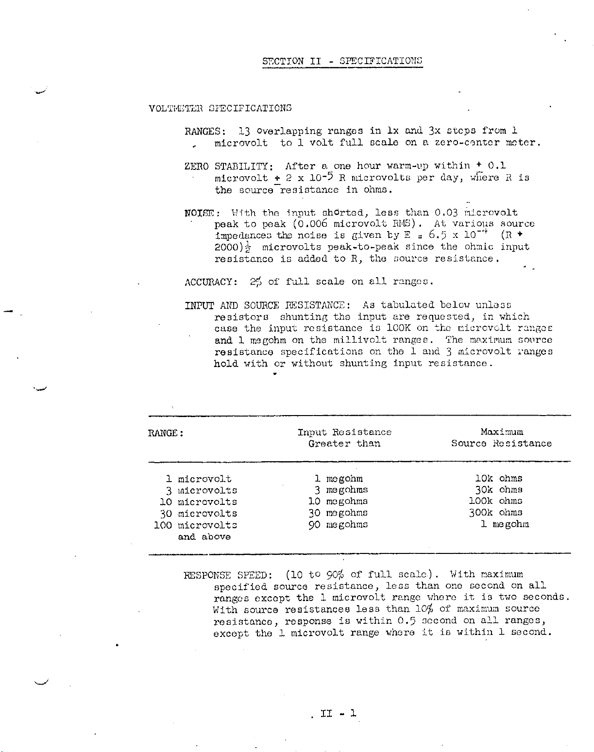
INPUT AhTD SOURCE RXSISTANCE: As tabulated bclov unless
RANGE:
Aftor n one hour warm-up within + 0.1
microvolt + 2 x lo-5 R
o~icrovolts
per day, -&rc i7 Is
the sourcerasiotancc in ohms.
b!ith the input shdrted, less than 0.03 !?!.crovolt
peak to peak (0.006 microvolt RW). At variol+s source
impcdlances the noiw is given by E =
6.5 Y
IO-+ (II +
2000); microvolts peak-to-peak since the ohmic input
reoistanco is added to R, the source resisfence.
_ .
25 of full scale on all rsngco.
resistors
shunting ths input are requested, in which
case the input resistance i3 1OOK on the micrcvclt rxgcc
and 1 megohm on tho millivolt rangee. The rw~xilwn sowcc
res-lstanco specificatisns on the 1 and 3 n:crovolt ranges
hold with or without shuntine input resistance.
.
Input Resistance
Greater thsn
Maximum
Source Hssistanca
1 microvolt
3 microvolts
10 microvolts
30 microvolts
100 microvolts
and above
F?ESPONSE SPEED: (10 to p@$ of full scale.). With maximum
specified source resistance, less than one second
ranges except the 1 microvolt renge whore it is two seconds.
b!ith source resistances less than 10% of maximw source
resistnnco,
except the 1 microvolt range where it is within 1 second.
1 me&ohm
3
megohms
10 megohms
30 megohms
90 megohms
10~ ohms
30~
ohms
1OOk ohms
300k ohms
1 megohm
on
all
response io within 0.5 second on all ranges,
.I1 -1
Page 5
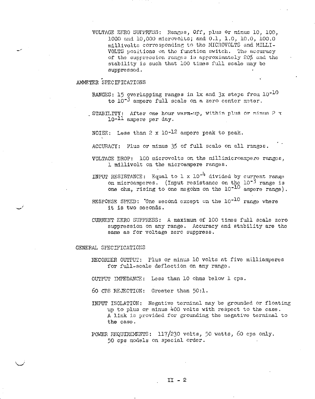
VOLTAGE ZERO SUPPRESS: Rnngos, Off, plllo or minus 10, 100,
lOQ0 and 10,000 microvolto; and 0.1, 1.0, 10.0, 100.0
m~~l.:~vo.ltn corresponding to tho MICROVOLTS and
MILLI-
VOLTS positions on tho function switch. Thu accuracy
of the
oupproooion rangco
1s approximately 2C$ and the
stability is such that 100 times full scale may be
suppressed.
RANGES: 15 overlapping ranges in lx and 3x steps frown lo-lo
to 10-3 ampere full scale on a zero center meter.
-.i
STARILITY:
After one hour warm-up,
lo-11 ampere per day.
NOISE:
ACCURACY:
VOLTAGE DROP:
INPIJP RESISTANCE:
Less than 2 x lo-12 ampere peak to peak.
Plus or minus 3% of full scale on all rangon.
100 microvolts on the millimicroampero ranges,
1
millivolt
on the microampere ranges.
Equal to 1 x 10m4 divided by current range
on microamperes. (Input resistance on the 10-j range Is
one ohm, rising to one megohm on the 10-l' ampere range).
RESPONSE SEZD :
'One second except on the 10-l'
it is two seconds.
CURlGNT ZERO SUPPRESS:
suppression on any range. Accuracy and stability are tho
same as for voltage zcrc suppress.
GENERAL SFECIFICAT';IONS
RECORDER OUTPUT:
Plus or
for full-scale deflection on any range.
within plus or minlui 2 x
'
range vhere
A maximum of 100 times full scale zero
minIA
10 volts at five milliamperes
OUTPUT IMPEDANCE:
60 ~7.5 RFJECTION:
INPU!I' ISOLATION:
Less than 10 ohms belou 1 cps.
Greater
than 5O:l.
Negative terminal may be grounded or floating
up to plus or minus 400 volts with respect to the case.
A link is provided for grounding the negatlvo terminal to
the case.
POWER REQUIREMWI'S: 11-f/230 volts, 30 watts, 60 cps only.
50 cps mod&s on special order.
II - 2
Page 6
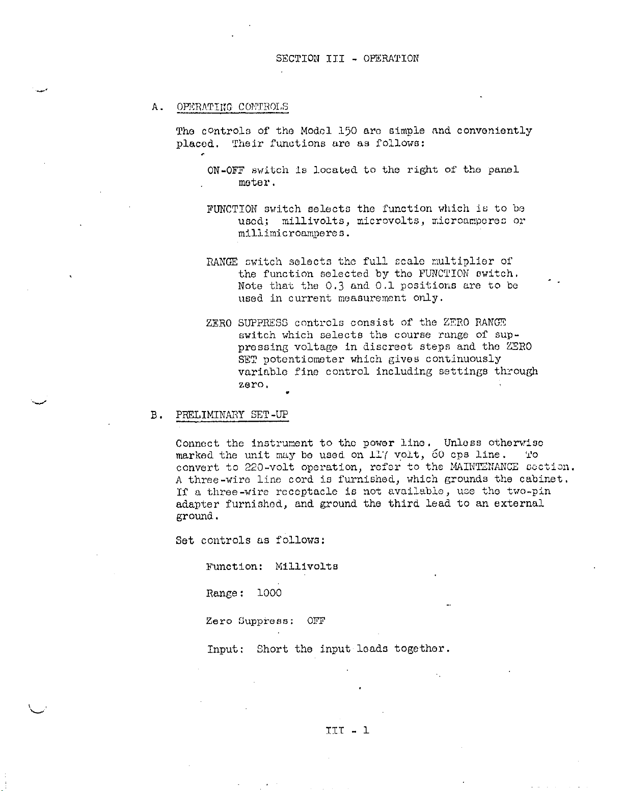
SECTION III - OPERATION
A. OPI?RATII:G COF!TROI.S
The controlo of the Modal 150 are simple and conveniently
placed. 'Their functions are as follo7m:
ON-OFF svitch is located to the right of the panel
motor.
FUNCTION switch selacto the function which is to be
used;
millivolts, microvolts, ;r.icromporco or
mlllimicroampores.
RANGX switch selects the full scale c!ultiplier of
the function selected by the FUNCTI@N switch.
Noto that the 0.3 and 0.1 positions are to be
used in current measurement only.
ZERO SUPPRESS controls consist of the ZERO IiANCX
switch which selects the course range of suppressing voltage in discreet steps and the ZERO
SET potentiometer which gives continuously
variable fine control including settings through
zero I
.
_ _
PREIJMINAPY SST-UP
B.
Connect the instrument to the power line. Unless othcrvioc
marked the unit nay be used on 117 volt, 60 cps line.
convert to 220-volt operation, refer
t0
the MAINTZ?!ANCE coctioll.
A three-wire line cord is furnished, which grounds the cabinet.
If a three-wire receptacle is not available, use tho two-pin
adapter furnished, and ground the third lead to an external
ground.
Set controls as follows:
Function:
Millivolts
Range: 1000
Zero suppress: OFF
Input:
Short the inputloads together.
TO
III - 1
Page 7

C.
GmmAL PRlVzAIJTIOIIS
Source Xesistanco - In SL'CTLON II - SPECIPlCATIOMS under XPU'I'
1.
AND SOURCE RE3IS?fJICE,
the maximum source rcsistancc for uuo wit!,
each voltage range is opecifi.ed. Reasonable operation is Pcssi~b1.o
with source resistances up to ten times gcater than thcso s;jeci-
fied, however the measurement will surfer from a considerable dccrease in speed of response, and measuring accuracy.
If the instrument is, left completely open-circuited, the meter >:ill Cc.ncra1l.y
drift off scale on any voltage range. On current ranges ihis does
not happen bocauso of the input ohuntinC resistors.
Shielding - Since the instrument operates with a mo3~~lo.t~ fx-
2.
quoncy of 120 cps,
it is not generally sensitive to 60
unless it is large enough to overload the amplifier.
cpn pickup
The pickup :n;y
be a source of difficulty when using the amplifier \Tith high imPeriaxes ox the more sensitive voltage rzngcs and on the t-.zo or three
most sensitive current ranges. In these cases it is desirable to
shiold,thc leads and the source 3s completely as possible.
cases a simple low-pass filter at the input to eliminate frec,uoncies
of about 1 cps and above will be helpi'ul. No use is made of an inout
filter in this
instrument since any input series impcdxince 13.x to :he
filter will increase the input noise and the thermal drift.
eratine above ground, the case of the instrument must be Croundcd.
In ooiae
When o,p -
Thermal EKF - Extreme precautions have been taken in the input
3.
circuit to minimize thermal EMF's so that the residual FXF is less
than 0.6 microvolt.
copper.
Any other metal will generat a thermoco)u?le potential.
The material used in the input circuit is pure
Load solder is perticularly troublesome. lihero thermal EXF's are a
problem, soldering should be done with the cadmium-tin solder supplied
with the instrunont.
4. Input Noise:
The noise at the input is a function of input re-
sistance and is approximately given by
E = 1.29 x 10⁻¹⁰ (R+2000)$
where E Is the IWS noise, and R is the source resistance. It Is as-
sumed that the bandwidth of the instrument is about 1 cps and the
temperature is 80°F.
noise and compare results.
resistors
approxil the
If noise is observed, calculate the theoretical
Also bear in mind that only wire-wound
ideal resistor. norrcvc r ) Lf Evx.o!13 or m&n-
ganin resistore are used, a considerable thermal3F of the resistor
material against copper will be observed.
Checking the Zero Point - At low levels, snurious FW's may be
5.
generated simptij by contact bctwoen
under test.
If possible,
always leave the instrument connected and
the input &ads and the terminals
,.
adjust the zero after establishing a zero reference in the apparatus
under test. For example,
in bridge measurements, disconnect the
bridge exciting voltage; or with a phototube, shield the tube from
light.
III - 2
Page 8

MI?ASUl~ING VOLTAGI?
D.
I.---
1.
Direct
Voltngc Meanurcmontn - Place the FUNCTION switch at
MILLIVOLTS or MICROVOLT'S ao nocossary for tho mousuroment to bc
taken. Thon turn tho RANQ? switch to more sensitive ranges until
the meter gives a uoablo dofloction.
Monsuring Voltagc Variations - Set the PUNCTIOX switch and RAI:GZ
2.
switch to obtain the best deflection of the mster. Use the ZXRO SUP-
PRESS controls as described in B to increase the sensitivity of tho
meter.
Then small changes In a relatively large steady signal may
be disnlayed with a large scale deflection.
3.
Masswing
Differential Volt&&es - ilhon mooeur'cmento are to bo
made in a circuit where the LOW connection is above Ground potential,
remove the DISCONNECT LINK from one of its posts.
This disconnects
the instrument circuit ground from chassis ground. 30 NOT attempt to
make such measurements where the low side of the circuit being measured Is more than 400 volts abcve external ground potential.
If a recorder is being used with the inntrumont in this arrangement,
the recordor ground must not bo connected
instrument since the low
side of the output would no longor be ground-
to the output ground of the
cd.
F 1. MEASURING CIJRRX7NT
Direct Current Reading - Turn the FUNCTION E3JITCR to MICROAHPS or
MILLIMICROAMPS,
and the RANGK SWITCE to 1000.
Connect the instrument
to the current source and set the RANGF SWITCH to the range which
gives the best deflection of the meter.
Measuring Current
VariatiOns -
Proceed as ubove fcr direct current
readings, and then use the Z3RO SUP?RXSS and ZERO SET as described
under B.
I?. OTlER APPLICATIONS
Null Indicator
1.
- The Model 150 makes an extremely sensitive null
indicator which may be used in a Wheatstone or Mueller Bridge.
In a Wheatstone Bridge, the Model 150 is connected between the two
resistor arm.
With the FUNCTION SWITCH on MICROA&G'S, and the 1PANGX
SJITCB on 1000, the bridge can be adjusted to give a zero reading
on the meter.
The instrument can then be set on more sensitive
ranges for finor adjustments of the bridge.* _,
Megohmmeter -
2.
The Model 150 may be used to measure rcsiotancos,
utilizing an external voltage source and measuring the current which
flows in the unknown.
*If the bridge is
arranged so that one terminal of -the dotoctor is
grounded, the Model 150 may be lbsed as described in X.1. If the
detector must be used floating,
remove the DISCONNXT LINK at thus
rear and observe the same precautions as in D.j.
III - 3
Page 9

SECTION IV - CIRCUIT DESCRIPTION
The Modrl 150 io bncicully a nnrrow-band
chopper
tivo l'oodback to Hxbilize the gain and incroaso
Input circuit
A.
Zero Stability: The effect of thermal EMF's
circuitry is reduced to nearly the vanishing
amplifier employing nogn-
the input impedance.
gcneratod.in the input
point by the use of only
copper or silver xaterials in the input circuit. All soIder joints
are made with a low thermal cadmium-tin solder. 'i'he chopper and
chopper transforrrer employ copper leads.
All twitching in tho input
circuit is accomplished with a solid silver swi.tch. Critics.1 resist.-
ors in tho input circuit are wound of copper wire. Tlio input connec-
tor has solid copper spring-loaded contacts.
The input voltage is applied to the moving arm of a 120 cps mechanical
chopper.
of the,input transformer.
The feedback voltage is connected to the primary center tap
Thus, the difference voltage is applied
first across ono half of the primary and then, with phase reversal,
to the other half.
This full wave error signal is stepped up 16 to 1
by the input transformer and applied to the grid of Vl, :: 6084 loo-
noise
B.
AC Amplifier
pentode.
In parallel with the plate load resistor of Vl is a relatively hi~gh
Q, 120 cps resonant circuit which narrows tho bandwidth and reduces
spurious signals.
"
V2 and V3, EF86 pentodes, further amplify the chopped error signs.1
which is then demodulated synchronously by germoniun diodes Dl andD2.
To obtain the 120 cps demodulator driving signal, use is nade c,C the
ripple frequency from a bridge rectifier circuit operating from tho
line voltage.
The ripple is connected to the primary of the demodu-
lator driver tranrformsr.
C.
DC Amplifier
The domodulated signal is applied to the grid of V4. V4,
V5, and
form the dc amplifier and output cathode follower which add further
forward gain to the system and supply output pc'zr. Feedback around
V4, V5 and ~6 m~ultiplies the effective capacitance of demodulator
filter capacitor Cl13 by about 1000.
This yields the large equiva-
lent capacitance necessary to smooth the demodulated error signal.
Because of the feedback,
spurious noise in the dc stages outside the
pass band of tho whole amplifier are effectively degenerated.
Zero Suppression
D.
A low-current + 10 volt supply is derived
using lo-volt Tener diodes.
voltage from -10 to +lO volto;
Potentiometer
this voltage being applied through ap-
from the main dc supplies
RI.74
ray be set at any
propriate dropping resistors to the feedback point. to achieve zsro
suppression.
ZERO SET, while switch
The potentiometer is the front panel control xarked
bW3,
which determines the portion fed back, is
labeled ZERO RANGE.
V6
N-l
Page 10

Other Controls
E.
Three controls are set at the factory and should rcqulro only lnfro-
qmnt attention by the user.
Hll8 Is an internal control marked DC AMP BAD.
the DC amplifier, I.e.,
domodulator output is zero.
balance will simply be fed back tc the in;lut
error signalto correct itself. Pi127 is msrked CAD. Thlo is the
variable portion of the mGter multiplier resistance to allow for
motcr-to-nu3ter sensitivity differences.
R177, marked CURXENT BALAWE, my be sot
cause a current to flow through R175 to the chopper ar:n. This cur-
rent is used to componsato for a small gcnoratod "chopper current"
which would otherwise flow in the input circuit. This "chopper
current" differs from chopper to chopper but is fairly stable for
long periods of tirce. Its effect on any current range could be rc-
moved with the ZERO SUPPRESS controls, but the Current 3alancc :%othod
used here gives an effective zero input current for all ranges.
Pwer Supply
I?.
A standard half-Irave rectifier followed by an R-C filter is used to
supply unregulated Bt and B- to the output cathode follower.
The unregulated B- is regulated to -150 volts in V7, OA2, and is
used for ths negativ: returns for the dc wplifier.
to set the output voltage to zero when the
This is not very critical since an un-
at some voltngo which will
It is used to zero
to
produce a s:aall
Unregulated B+ is fed to the plate of V8, 12Rll.A, the series tube in
a 225-volt electronic regulator. The output voltage from this rcgu-
lator is divided by R510 and R511 and compared to reference tuba V9,
a 5651.
a 12AX7,
This regulated 225 volts supplies B+ directly to the dc amplifier,
through a decoupling filter
amplifier stages, and through another decoupling filter (R103, ClO4)
to the first ac amplifier stage,
Regulated B+and B- also supply currents to the 10 volt zener diodes
which are used for zero suppression. This gives two-stage regula-
tion for these very critical voitages.
The first two ac amplifier filaments and the first dc alnplifior
filaments are driven by a bridgo-rectified
The R-C filter sections R5l2, C507, R513, C508, insure low ripple.
The difference signal is amplified by cascade amplifier VlO,
and applied to the grid-cathode circuit of the series tubs.
(2176,
CllO) to the second and third ac
6-volt
d.c. supply.
IV-2
Page 11

SECTION V - MAINTENANCE
Rxccpt for occasional tube or chopper replacement, very little mainton-
ante is required by the Models 150 and 150R.
Components are operated.
well below rating and solid-stato devices arc employed where possible
to achieve long, trouble-free service.
Certain portions
special cadmium-tin solder.
of the input circuit are wired using copper'wlre and
These special joints are painted red.
If, for any reason, those joints must be unsoldered or re-soldcrod,
USE ONLY CfZ?4IUM-TIN SOLDER AND A COPPZR-TIP?ED
iu\S hWJER BLTV; USZD WIUf 0FJI:IARY L,E!D-TIN SOLDRR. A small
SOLDERING IRUN WHICH
~~301 Of
cadmium-tin solder is supplied with each instrument.
What may seem to be circuit failure in the Micro Volt-kmxeter is quite
often found to be an unusual condition in the entire test set-up.
Therefore; before trouble-shooting the instrur;ont, :hock to sei: wh;cthcr
it operates correctly with:
All other circuitry disconnected.
1.
Input shorted (with copper loads).
2.
power line voltage and frequency correct.
3.
If the difficulty persists,
the following systematic procedure may be
' .
employed to determine the fault.
TROLDLF-SHOOTING
"
Reference is made to the Schematic Diagram, DR 12188-D, and the VoltageResistance Diagram enclosed at the rear of tho manual.
To bogin trouble-shooting, short the input teninLls, strap chassis
ground to LO with the link provided,
and switch ZERO R;L":CZ to CIt'F . :;
Zero offset of a few tenths of a microvolt is normal. on C~Jrront func-
tions with the input terminals open but shielded, it should be possible
to sot zero current with the CURPJNT BALANCE control at the rear of tho
instrument.
EXCESSIVE OUT?UT NOISE (mU'I 'IB'RMINALS SHORTED)
Short the input grid of the dc amplifier, pin '/ of VI+, to ground. If
this stops the noise,
tunately, because of the very low signal
it is being generated in the ac amplifier. unfor -
levels involved, noise in the
ac amplifier is difficult to trace by other thanthe s.ubstitution method.
Most logical noise sources are Vl or the chopper. To replace the chop-
per, unplug the cap at the
top,
which clamp the chopper loads.
and lift out the chopper.
the chopper leads are preol
insulating washers
are between the leads and the thumb-screw nuts.
When inserting the new chopper, make sure that
q.-ed against the copper terminals and that the
and unscrew the three thumb-screw
Unscrew the two chopper mounting screws
nuts
Observe color-coding on the leads.
V-l
Page 12

If thu no-isc Pornl.oto aftor short<n(j the dc amplifier input, the noise
So being ~:~ri~ratod in the dc nm],lif!.er or power nupply.
stn@
search should reveal tho source.
A stnce-hy-
OUTPUT NOT I,I?RO (I?tT,TuT 'IYRMINALS SHOR!l??;,)
Be 8ure that ZERO RANGE is set to OFF.
erIcI, &-( of V4, %o grolmd.
Use the DC AMP BAL Control to sot the
Short the dc amplifier inpu~e
outpui to zero, If this cannot be done, the dc ampl;fier or power
oupply are at fault.
If It can be sot to zero, the trouble may be in
the RC amplifier or demodulator cj,rcuit.
Power Supply - B+ should be about +225 cn pin 1 of 'Jr,, arxi
a.
B- should be -130 on pins 2, 4 or 7 of V7.
correct the fault in the unre&Qlu.ted B-.
If V7~ Is cot firing,
I? t225 5~3 not present.,
check for unregulated B+ (about 340 volts) at the plate pin 9 of
va. If the unregulated B+ j8 all right,
check the tube pin volt-
ages of V8, V9, tLnd VlO to locate the faulty tube or part. .
AC Amplifier - Remove the output tube (~6) and clip pin 1 of
b.
the output connector to ground. Place the XJNCTION sw!tch on
MILLIVOLTS, and turn the ZERO SET and ZERO RANGE controls, full
clockwise. This putn a large dc error signal across the chopper
and input transformer.
Use an oscilloscope to check for the
preoence of 120 cp8 at the primary of the input transformer (the
two outside terminals on the chopper terminal block). Absence of
signal means chopper failure (or much less likely, shorted input
transformer).
Listen for audible chopper
action
and check chopper
drive, if riecessary.
If the 120 cps oignsl is present,
check stage-by-stage throughcut
the ac amplifier, reducing the Input signal a8 desired by backing
off the ZERO RANGE and/or ZERO SET controls,
until the failure is
discovered.
Demodulator Circuit - Check for presence of about 80 volts RYS
d.
at the secondary of the demodulator transformer (at the ends of R113
ond R114).
The tests outlined above will not suffice to pin-point every fault
which may exist. They should, however, lead to the correction of
common failures.
by these means,
In.the event that troubles cannot be corrected
or the user finds it more expedient, the unit may
be returned to the factory for repair and recalibration at a
nominal cost.
220 VOLT OPERATION
-
For 220'7 operation the powor tranofnrmer primary connections munt be
changed.
The jumpers connectingblack and black-white together, and
blue and blue-white should be removed. The blue lead should be tied
to black-white.
v-2
Page 13

RcplacecLbla Part.0 List Model
150 - 15m
CTrcuit
Dc~.
Cl01
Cl02
Cl03
c 104.
ClO:,
Cl06
Cl07
Cl08
Cl07
Cl10
Cl11
Cl12
Cl13
Cl14
Cl15
~116
Cl17
Cl18
c;o1
c502
c503
CTjO4
csolj
C506
c507
~508
cyog
Deficription
Capacitor, mylar colected,
Capacitor, tubular, electrolytic, 5 mfd,
Capacitor, metalized paper 0.1 mfd, 200 VDCW
Ca&citor, tubular, electrolytic, $0 mfd,
Cap$citor, mylar dielectric, .l mf'd, 400 VDCW
Capacitor, mylar dielectric for
.0082 mfd, l$, 100 WCW
Same 88 Cl02
capacitor, ceramic disc, .Ol mfd, 600 VDCW
.047 to .33 r&-d, 200
15
VDCW
450 VECW
50
cycle model
VDCW
Sam0 89 Cl03
Same a,.¶ Cl04
'Same as Cl02
Same Lt8 Cl05
.333
Capacitor, mylar dielectric,
Capacitor, ceramic disc,
Capacitor, ceramic disc,
.ool rc;‘d, 600 'VQCW
.OCb7
mfd, 2C0 VDCW
mfd, 600 VDCW
same a3 Cl14
Capacitor, padding
Capacitor, metalized paper, 1.0 mfd, 200 VIEW
Capacitor, tubular, electrolytic, 20 mfd, 600 VEW
780
-2110 mmf
SHm3 an Cl04
Same I38 c501
same as cl08
Same as Cl04
Capacitor, mylar dieiectric, 4.0 mfd, 600 VDCW
Capacitor, tubular, elec.trolytic, 1000 mfd, 12 VECW
&me 8.6 c507
Sane e.8 Cl05
I
i Part ND.
Cll-5
c18-.I.
CA-2OL
c30-.l
I
.
c45-.ooe2
c22-.OL
C29-.333
c22-.
001
C22-:a047
c51-7co-2110
ClR-1.0
C35--20
c50-4.0
Cll-1000
CHl
CSl
cs2
CUl
Dl
D2
D3
n4
Fl
M
RlOl
R102
RlO3
n104
R 105
R105
tiloT
RlOO
lx109
I?110
Rlll
Choke, 200 M., 120 cpn Hi Q
Connector, input, special
connector, output, Amphenol 80 PC 2~
Chopper, frequency, doubling, special 60 cycle
50 cycle
Diode, Selenium, International Rect. Corp. 501
Sane &s Dl
Diode, Zener, Hoffman Semiconductor ZAlO
Same a.8 D3
Fuse, PiA,
Meter, Panel, 200 lnicro amp zero center
Resistor, composition, 33K, l@, $!J
Resistor, S.S.
Hesifitor, composition, 47IC, lCJ$, +W
Resistor,
Resistor,
Rcsintor, deposited carbon, 1 meg, l$, SW
Resistor, componition, 22K, I@, $W
Resistor, composition, 3.3 meg, lC$, $W
Same as R104
Same FLB R107
3AG
(llOV), Fuse, IA, 3AG (220V)
White, low noise 2X, l$, 1W
composition, 1 meg, lC$,
composition, 3.3 meg, l$, $I<
+W
same ELS ~106
CHl
cs 32
cv2
CV3
RF 15
DZ-ZALO
FUB-FU~
ME-I.4
Rl-33K
R44-2M
Rl-47K
Rl-l.M
Rl-3.3M
R12-1M
Rl-22K
Rl-3.3M
Page 14

V
Circuit
I-MS
--.-A-...Ii112
R113
R114
Hll.5
EllC
R117
Rll8
H119
Rl20
R121
R122
R123
R124
n125
Fi126
R127
RI28
Rl29
Deecription
Ecaistor, deposited carbon, 2OOK, i$, *W
Resistor, deposited
carbon, lOOK, l$, &
Sam0 a6 R113
Resist&, deposited carbon, 1.2 meg. l$, $W
Renistor, deposited carbon, 47CK, l$, .'-W
Reoistor, depoaS.ted carbon, 333K, l$, 2W
Potentiometer 500K ohms
Register, deposited carbon, 68OK, l$, 3
Sue a6 RlO5
Resistor, depooited cat-bon, 2.2 meg. l$, $W
Resistor, deposited carbon, 6OK, l$, SW
~Same as R113
Same a8 RlO6
same as R106
Resistor, wirewound 3OK, lC$, 1OW
Potentiometer, 1CK ohms
Hecintor, deposited carbon, 96~, is, $W
Resistor, composition, 22K, 16, 2W
f
Part No.
H12-200K
Rl2-100K
R12-1.2Ll
R12-470Y
H12-333K
RPy.2
R12-&ii
H12-2.2M
R12-631:
R5-3G-C
RP9-1OK
R12-96K
~3
-.22K
L
‘ti
R134
N135
~1.36
R137
~138
R140
n14-1
Rl42
R143
.Rlh4
Ii145
R14.Z
HI.47
11148
Rl49
1~150
R151
Rl52
R153
11154
Rl55
Ii156
Rl57
R158
111'9
H160
~161
RI62
RI63
Rl64
H16Fj
R166
R167
Rl68
Rl69
R170
Reoisto?, special, copper wirewound 10 ohms, 15
Resistor, qecial,
Resistor, deposited carbon, special, l.llX, l$, $W
Resistor, deposited carbon, special, lOOK, l$, SW
Resistor, special, copper *direwound, 1OK ohms, 5%
Reoistcr, deposited carben, lOK, l$, $W
Rcoistor, dcposised carbon, 3.33K, 174, -$W
Resistor, deposited carbon, lK, l$, $1
Resistor; depwited carbon, 333 ohms, 1% lW
Resistor, deposited carbon, 100 ohms, lp, 2
Renjstor, deposited carbon, 33.3 ohms, l$! +W
Resiotor, deposited carbon, 10 ohms, l%, 2W
Resistor, deposited carbon, 3.33 ohms, l$, &W
Resistor, deposited carbon, 1.0 ohms, l$, $W
Sum CL.9 R106
Same as R117
Same as R113
Resistor,
Resistor, dcpoeited carbon, 500 ohms, l$, $W
Same &s R153
Resistor, deposited carbon, 10 meg, l$, 1W
Same as R105
Eame tm R106
Same a~ R117
Resistor, deposited carbon, 99K, l$, $W
Resistor, deposited carbon, 32.3K, l$, +W
Resistor, deposited carbon, 9K,~ l$, $W
Reoiotor, composition, lOOK, lO$, SW
Resistor, composition, 39OK, 16, $W
deposited carbon,
copper wirewound 1OK ohns, 1%
$' f.w
33.39, l$, +W
SW aa ~162
Resistor, composition, 47K, lo?/p, $W
Rooistor, composition, 15K,
lC$, -.$
Resistor, composition, 4.7X, lO$, $W
Resiotor, componition, 1,5K, l$, qW
Resistor, compooition, 4700 ohms, lC$, +W
Resistor, depositad carbon, IX, l$, $W
R18-18-10
Rl&lC-lC!X
R38-l.llK
R38-109~
RlB-lg-.lCK
R12-1OK
R12-3.33K
R12-IX
R12-333
R12-100
R12-33.3
R12-19
~12-3.33
R12-1.0
R12-33.3K
~12-500
R13-10M
R12-99K
1712-32.3~
~12-91~
Rl-100K
Rl-390K
Rl-47K
Rl-15K
Rl-4.7K
Rl-1.5K
Rl-4700
R12-lK
Page 15

“ci
circuit
D0s.
Rl’ll
HI.72
x173
R174
R175
Description
-.------.Snmo as RlO6
Same as H113
Potentiometer, 10 turn, 1OK
Resistor, deposited carbon, 100 meg, l$, 2W
-- ----
HP4-1OK
R14-1OOM
L’
n177
R178
R179
Ii160
Rl81
X182
R501
R'j02
8503
R504
n505
R506
R5o7
R509
R509
R510
R511
R512
R513
RF1 thru
RF10
RF11
Sam as R127
Resistor, deposited carbon, 75K, l$, &W
SC&~ as R178
Same as R126
Resistor wirewound, special, customer request only
Resistor, deposited carbon, 1 megj l$, -$
customer request
Resistor, composition, 100 ohms, lo;",, 2W
Sam as R501
Resistor, wirewound, 5K, lC$, 1OW
Same as R503
Resistor, composition, 22K, I-@$, 2W
Resistor,
Resistor, deposited ccrbon, 220K ohms, l$ $W
Same as RlOl
Same as RlOl
Seam s.8 R106
Resistor,
Resistor, wirewcnnd, 6 ohms, I@, 5~
Resistor,
Rectifier,
Rectifier, bridge,
composition, 10
dep0oited
wirewound, 5 ohms, l@,
selenium, 13Ov, 65ma
carbon, HOOK, l$, $W
26
meg.
volt, 6OOma
lC$, $W
5W
R12-75K
RIG-&!l-1COK
R12-1M
R3-100
n5-5If
R3-22K
Rl-1OM
R12-22CK
~12-60m
R4-6
R4-5
RF6
RF7
u
SW1
SW2
SW3
SW4
TRl
TR2
m3
Vl
v2
'J3
v4
v5
V6
V7
VR
v9
VlO
Function switch, 4 pole, 4 position
Rongo switch, 9 position
Zero suppress, zero range 5 position
Power switch, D.P.D.T.
Power transformer Central KI-129
Demodulator transformer Central KI-128
Input transformer, #James Cl635 special
Pilot lamps (2)
Vacuum tube, type
Vacuum tube, type
Same
Vacuum tube, type 12.4X7
Vacuum tube, type
Vacuum tube, type
Vacuum tube, type OA2
Vacuum tube, type 12B4A
Vacuum tube, type 5651
Same as V4
as V2
6.3~.
6084
EF86
12AT7
6CM6
0.15
amps G.E. type
47
SW56
SW54
sw58
SW14
TR27
~~26
Tn2a
PL4
~~6084
EV-RPa6
w-12.2X7
EV-12AT7
EV-6Cfr6
EV-OA2
EV-12B4A
~~-5651
EV-5651
Page 16

.
Page 17

^_.._
I-‘-‘--
v-- ---
 Loading...