

Page 1
INSTRUCTION MANUAL
MODEL 15OB
MICROVOLT AMMETER
Page 2
WARRANTY
We warrant each of our products to be free
from defects in material and workmanship. Our
obligation under this warranty is to repair or
replace any instrument or part thereof (except
tubes and batteries) which, within a year after
shipment, proves defective upon examination.
We,will pay domestic surface freight costs.
To exercise this warranty, call your local
field representative or the Cleveland factory,
DDD 216-248-0400. You will be given assist-
ance and shipping instructions.
REPAIRS AND RECALIBRATION
Keithley instruments maintains a complete re-
pair service and standards laboratory in Cleve-
land, and has an authorized field repair facility
in Los Angeles.
To insure prompt repair or recalibration serv-
ice, please contact your local field representative or the plant directly before returning the
instrument.
Estimates for repairs, normal recalibrations,
and calibrations traceable to the National Bureau of Standards are available upon request.
Page 3
MODEL 150B MICROVOLT AMMETER
TABLE OF CONTENTS
TABLE OF
Section
MODEL 150B SPECIFICATIONS. .... .ii 4. MAINTENANCE. . . . . . . . . . . 19
1. GENERAL DESCRIPTION. ........
l-1.
l-2. As a Microvoltmeter. ..... 1
l-3.
l-4 .. As an Ammeter. ........ 1
2. OPERATION. ............. 3
2-1.
2-2.
2-3.
2-4,.
2-5.
2-6.
2e7.
2-8.
2-9.
2-10.
2-11.
2-12.
2-13.
Z-14,.
2-15.
2-16.
CIRCUIT DESCRIPTION. ., . . . . . . .13
3.
General. ...........
As a Null Detector ...... 1
Mode of Operation. . . . . .
Battery Operation. . . . . .
Microvolt and Null Detector
Operating Procedures . . . .
Ammeter Operating
Procedures . . . . . . . . .
Zero Suppress Operation. . .
Filter Switch. . . . . . . .
Recorder Outputs . . . . . .
Synchronizing Terminals. . .
Differential (Floating)
Measurements . . , . F . . .
Accuracy Consideration . . .
Thermal Noise. . . . . . . .
Input Resistance . . . . . .
Therinal Emf's. . . . . . . .
Shielding. . . . . . . . . .
Operating From Source Other
Than 117 Volts, 60 cps . . .
Accessories For Input
Connections. . . . . . . . .
Page
.3
.3
. 4,
.6
.6
: 7
.7
.8
.8
: 9
. 9
.lO
.ll
.ll
CONTENTS
1
1
7
0
Section
4,-l.
4-2.
4,-3. Mechanical Chopper
4,-4,. Troubleshooting. . . . . . . 20
4-5.
4,-6. Check Out and Calibration
4-7.
4,-a. Amplifier Check Out
ACCESSORIES. . . . . . . . . . . . 35
5.
5-l.
5-2. Model 4007 Dual Rack
5-3.
6. REPLACEABLE PARTS. . . . . . . . . 41
6-l.
6-2. How to Order Parts . . . . . 41
General. . . . . . . . . . . 19
Parts Replacement. . . . . . 19
Replacement. . . . . . . . . 19
Preliminary Troubleshooting
Procedures . . . . . . . . . 20
Procedures . . . . . . . . . 20
Power Supply Check Out
and Calibration. . . . . . . 22
and Calibration. . . . . . . 25
Model 4,006 Rack
Mounting.Kit . . . . . . . . 37
Mounting Kit . . . . . . . . 37
Model 370 Recorder . . . . . 39
Replaceable Parts List . , . 41
Model 150B Replaceable
Parts List . . . . . . . . . 42
Models 14,83, 14.84
Replaceable Parts List . . . 50
Schematic Diagram 20350E . . 53
Schematic Diagram 20357D . . 55
Page
3-1. General. . . . .
3-2.
3-3.
3-4..
3-5.
3-6.
3-7.
3-8.
0667R
Input Circuit. .
AC Amplifier . . .....
Demodulator. . . ... * ..
DC Amplifier . .
Zero Suppression .....
Power Supplies . .....
Battery Charging
, ......
.......
......
Circuit .. .17
13
13
. .14.
.15
.15
. .15
. .15
* Change Notice Last page
* Yellow Change Notice sheet is included
only for instrument modFfications affect-
ing the Instrument Manual.
i
Page 4
GENERAL DESCRIPTION
MODEL 150B MICROVOLT AMMETER
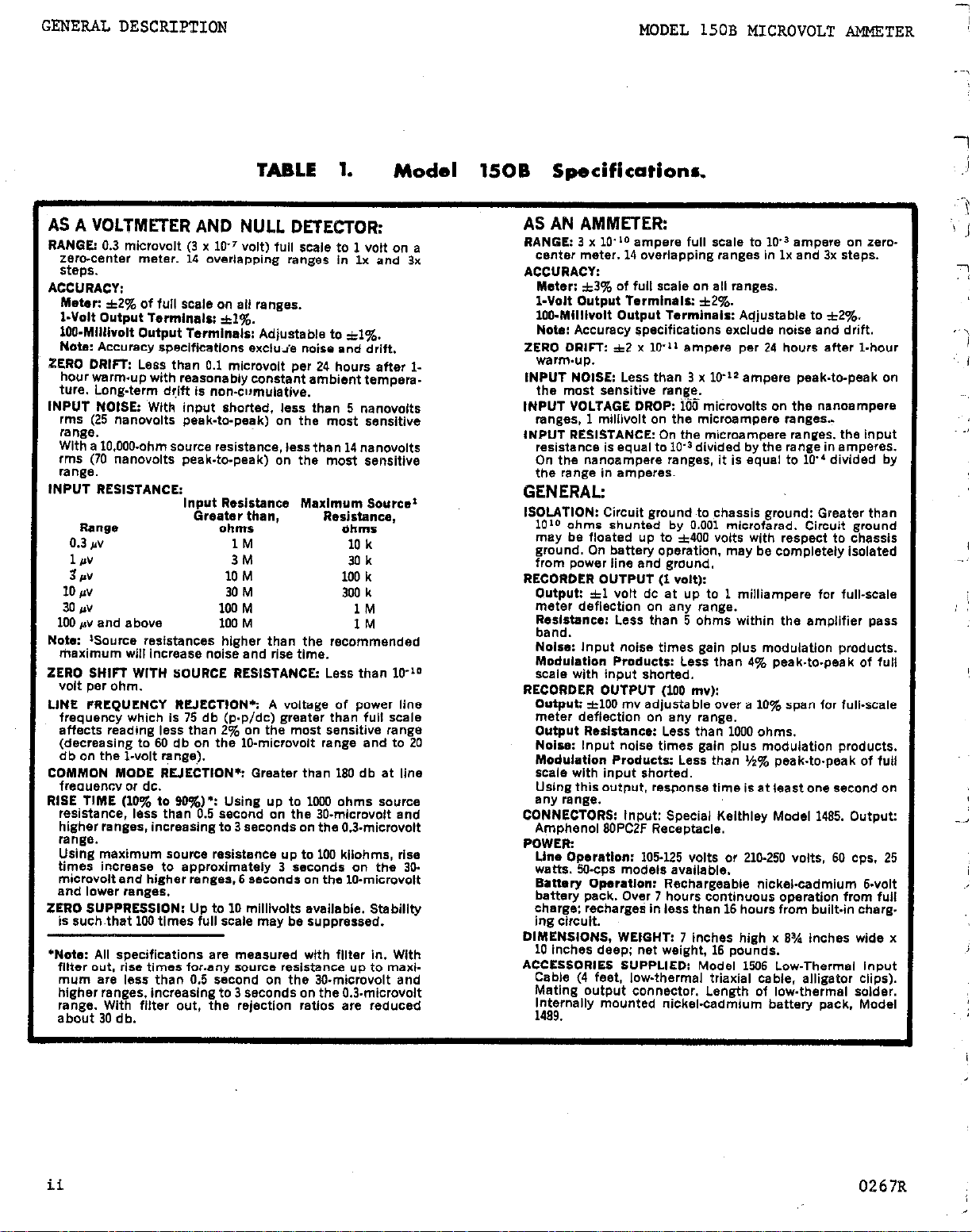
TABLE 1.
Model 1SOB Specifications.
AS A VOLTMETER AND NULL DETECTOR:
RANGE: 0.3 microvolt (3 x 10-’ volt) full scale to 1 volt on a
Zero-centw meter. 14 overlapping ranges in Ix and 3x
steps.
ACCURACY:
Meter:
*2g Of full scale on all ranges.
I-Volt Output Terminals: *I%.
100.Millivolt Output Terminals: Adjustable to ~1%.
Note: Accuracy specifications excluie noise and drift.
ZERO DRIFT: Less than 0.1 microvolt per 24 hours after I-
hour warmup with reasonably constant ambient tempera.
ture. Long-term d!ift is ncwcumulatlve.
INPUT NOISE: ‘With input shorted, less than 5 nanovolts
rms (25 nanovolts peak-to-peak) on the most sensitive
range.
With a 10,000.ohm source resistance. lessthan 14 nanovolts
rms (70 nanovalts peak-to-peak) on the most sensitive
range.
INPUT RESISTANCE:
Range
0.3 IN 1M
1 P”
3,
10 pv 30 M
30 IN 100 M
100 #v and above 100 M
Note: ‘Source resistances higher than the recommended
maximum will increase noise and rise time.
ZERO SHIFf WITH SOURCE RESISTANCE: Less than
volt
per ohm.
LINE FREQUENCY RUECTION’: A voltage of power line
frequency which is 75 db (p.p/dc) greater than full scale
affects reading less than 2% on the most sensitive range
(decreasing to 60 db on the 10.microvolt range and to 20
db on the l-volt range).
COMMON MODE RLIECTIDN*: Greater than
frequencv or dc.
RISE TIME (10% to 90?&)? Using up to 1wO ohms source
reSistanCe, less than 0.5 second on the 30.mlcravolt and
higher ranges. increasing to 3 seconds on the 0.3.microvolt
range.
Using maximum source resistence up to 100 kllohms, rise
times increase to approximately 3 seconds on the 30.
microvolt and higher ranges. 6 seconds on the lo-microvolt
and lower ranges.
ZERO SUPPRESSION: Up to 10 millivolts available. Stability
is such.that
‘Note: All specifications are measured with filter in. With
filter out. rise times forany source resistance up to maxi.
mum are less than 0.5 second on the 30.microvolt and
higher ranges. increasing to 3 seconds on the 0.3.microvolt
range. With filter out, the rejection ratios are reduced
about 30 db.
Input Resistance Maximum Source*
Greater than,
ohms
3M
10
M
100
times full scale may be suppressed.
Resistance,
Ohms
10 k
30 k
100 k
300 k
1M
IM
180
db at line
1o-‘o
AS AN AMMETER:
RANGE: 3 x lOLo ampere full scale to
center meter. 14 overlapping ranges In lx and 3x steps.
ACCURACY:
Meter: a3% Of full Scale on ali ranges.
I-Volt Output Terminals: *2%.
100.Mllllvolt Output Terminals: Adjustable to +2q6.
Note: Accuracy specifications exclude noise and drift.
ZERO DRIFT A2
werm.up.
INPUT NOBE: Less than 3 x 10’12 ampere peak.to-peak on
the most sensitive ran,~e,
INPUT VOLTAGE DROP: 100 microvolts on the nsnoampere
renges, 1 millivolt on the microampere ranges..
INPUT RESISTANCE: On the microampere ranges. the input
resistance is equal to lo” divided by the range in
On the nanoampere ranges, it is equal to
the range in
x lo’”
amperes~
ampere per 24 hours after
1W3
empere on zero.
lo”
divided by
l.hour
amperes.
GENERAL:
ISOLATION: Circuit ground ,to chassis ground: Greater than
1O’O ohms shunted by 0.001 microfarad. Circuit ground
may be floated up to ~400 volts with respect to chassis
ground. On battery operation. may be completely isolated
from power line end ground.
RECORDER OUTPUT (1 volt):
Output: ztl Volt dc et up to 1 milliampere for full-scale
meter deflection on eny range.
Resistance: Less than 5 ohms within the amolifiar oass
band. band.
Noise: Input noise times gain plus modulation products. Noise: Input noise times gain plus modulation products.
Modulation Products: Less than 4% peak.to-peak of full Modulation Products: Less than 4% peak.to-peak of full
Scale with input shorted. Scale with input shorted.
RECORDER OUTPUT
Output: ztlO0 mv adj;stabi;&er a
meter deflection on eny range.
Output Rsslstancs: Less than 1000 ohms.
Noise: Input noise times gain plus modulation products.
Modulation Products: Less than ‘/z% peak.to.peak of full
scale with input shorted.
Using this output, response time is at least one second on
any IB”B.3.
CONNECTORS: Input: Special Kelthley Model 1485. Output:
Amphenol BOPCZF Receptacle.
POWER:
Line Dperatlon: 105125 volts or 210.250 volts, 60 ops. 25
watts. 50.cps mode18 available.
Battery Operation: Rechargeable nickel-cadmium &volt
battery pack. Ov?r 7 hours continuous operation from full
charge: recharges in less than
ing circuit.
DIMENSIONS. WEIGH(T: 7 inches high x 8% inches wide x
10
inches deep; net weight, 16 pounds.
ACCESSORIES SUPPLIED: Model
Cable (4 feet, low-thermal triaxial cable, alligator clips).
Mating output connector. Length of lowthermal solder.
Internally mounted nickel.cadmium battery pack. Model
1499.
1100
1100
mv): RECORDER OUTPUT
mv):
10%
spa” for full-scale
16
hours from built.in charg.
1506
Low.Therma, Input
ii
0267R
Page 5
MODEL 150B MICROVOLT AMMETER
GENERAL DESCRIPTION
SECTION 1.
l-l.
instrument which measures voltages from 0.3 microvolt to 1 volt and currents from 0.3
nanoampere
with either battery or line power operation.
l-2.
thermopile and thermocouple potentials, Hall effect, contact resistances, biologically
generated emf's, electrochemical potentials and strain guages emf's.
sistance and loti zero shift; excellent zero stability;
and common mode rejection; battery operation; zero suppression;
circuitry;
ment accuracy even from high resistance sources; is ideal for long-term measurements; de-
tects dc signals in the presence of large ac voltages and is virtually insensitive to nc
or dc voltages applied between circuit and chassis ground;
for improved isolation; measures small changes in dc signals: reduces temperature and shielding problems; provides outputs where either filtering is needed or fast response or greater
output power is needed.
GENERAL.
AS A MICROVOLTMETER.
a. The Model 150B is ideal as a microvoltmeter for measuring semiconductor resistivity,
b. The Model 15OB has input noise less than 25 na,novolts peak-to-peak; high input re-
c. With these features, the Model 150B permits excellent resolution; maintains measure-
The Keithley Model 150B Microvolt Ammeter is an extremely sensitive
to
1 milliampere. It can be used as a voltmeter, null detector or an ammeter
two available outputs.
GENERAL DESCRIPTION
very high line-frequency rejection
special low-thermal input
disconnects from power lines
l-3. AS A NULL DETECTOR.
As a null detector the Model 15OB is excellent for use in ratio measurements and in
a.
potentiometer and bridge circuits.
b. The Microvolt Ammeter's outstanding features as a null detector are:
solution; high line frequency and cormnon mode rejection; isolation from chassis ground to
input terminals; battery operation; high input resistance; floating capability; low zero
shift;
C.
usable resolution of most potentiometers and bridges; may be simply connected to the terminals of a null circuit; is very insensitive to commnn mode voltages developed in the
null circuit; can be used in most potentiometer and bridge circuits without off-null load-
ing; accurately detects a null regardless of the setting on most potentiometers and bridges;
compensates for thermal emf's generated in the null circuit.
1-4. AS AN AMMETER.
It is useful for making low voltage drop,
output of radiation detectors,
.._
b.
low zero drift for measuring long-term current; excellent floating capabilities for measuring ungrounded sources;
zercl suppression.
Because
a. The Model 150B has general use in research,
The instrument has low voltage drop for measuring currents in very low-voltage circuits;
of these features the Model 150B has resolution comparable to the maximum
design and production test facilities.
in-circuit measurements as well as measuring the
phototubes and other current generating transducers.
and low input noise,giving excellent resolution.
very good re-
'.
0667R
1
Page 6
OPERATION MODEL 150B MICROVOLT AMMETER
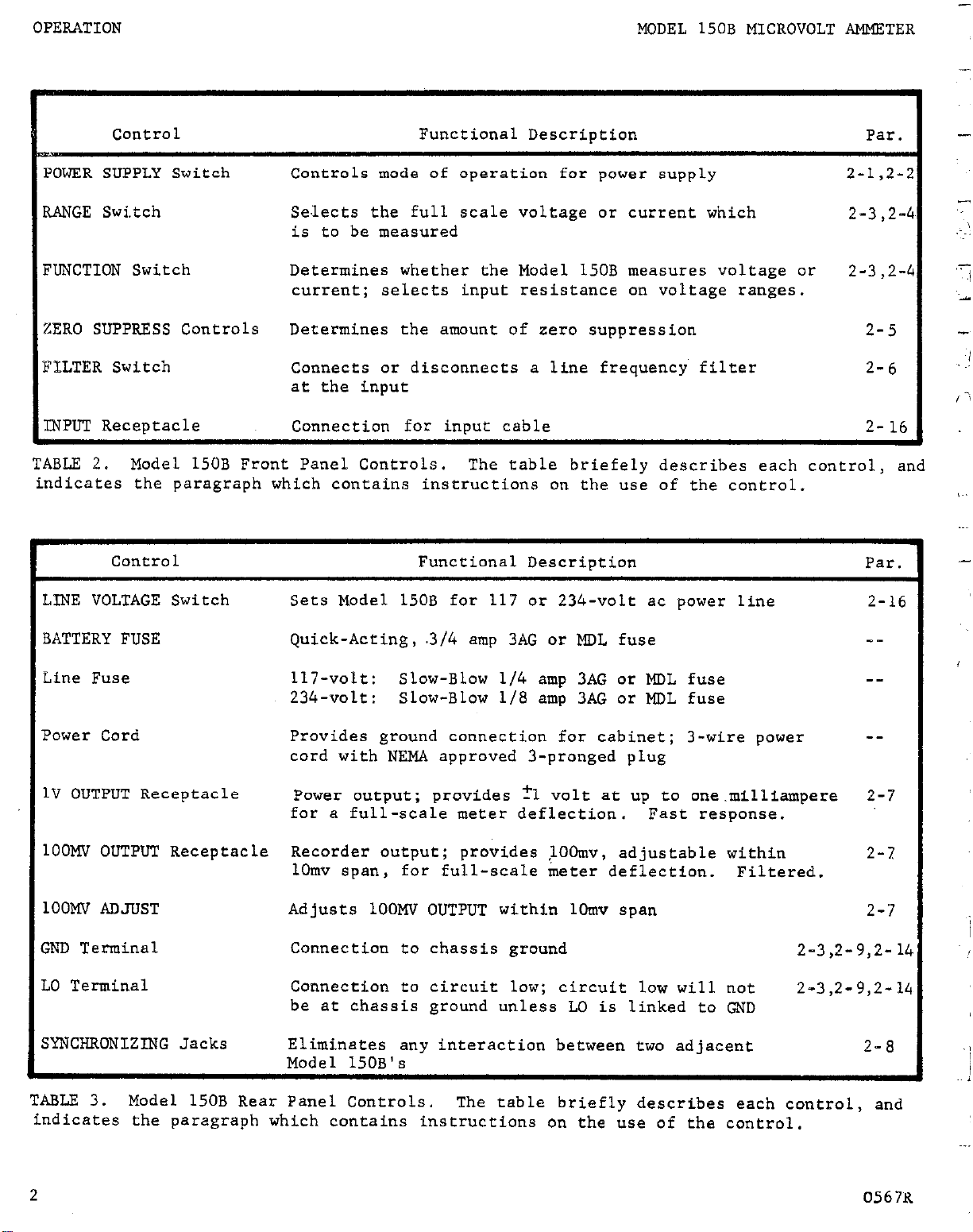
Control
JEER SUPPLY Switch
4NGE Swi.tch
UNCTION Switch
ERO SUPPRESS Controls Determines the amount of zero suppression
LLTER Switch Connects or disconnects a lfne frequency filter
gPLIT Receptacle Connection for input cable 2-16
TABLE 2.
indicates the paragraph which contains instructions on the use of the control.
Model 150B Front Panel Controls.
Control
Controls mode of operation for power supply
Se.lects the full scale voltage or current which
is to be measured
Determines whether the Model 150B measures voltage or 2-3,2-
current;
at the input
Functional Description
selects input resistance on voltage ranges.
The table briefely describes each control, and
Functional Descriotion Par.
Par.
2-1,2-
2-3,2-
2-5
2-6
LINE VOLTAGE Switch
BATTERY FUSE
Line Fuse
Power Cord
1V OUTPUT Receptacle
1OOMV OUTPUT Receptacle
1OOMV ADJUST
GND Terminal
LO Terminal
SYNCHRONIZING Jacks
Sets Model 150B for 117 or 234-volt ac power line
Quick-Acting, .3/4 amp 3AG or MDL fuse
117-volt: Slow-Blow l/4 amp 3AG or MDL fuse
234-volt: Slow-Blow l/8 amp 3AG or MDL fuse
Provides ground connection for cabinet; 3-wire power
cord with NEMA approved 3-pronged plug
Power output; provides ?l volt at up to one.milliampere
for a full-scale meter deflection.
Recorder output; provides >OOmv, adjustable within
1Omv span, for full-scale meter deflection. Filtered.
Adjusts 1OOMV OUTPUT within 1Omv span
Connection to chassis ground
Connection to circuit low; circuit low will not
be at chassis ground unless LO is linked to GND
Eliminates any interaction between two ad~jacent
Fast response.
2-16
__
--
--
2-7
2-7
2-7
2-3,2-9,2-14
2-3,2-9,2-14
2-8
TABLE 3.
indicates the paragraph which contains instructions on the use of the control.
2
Model 150B Rear Panel Controls.
The table briefly describes each control, and
0567K
Page 7
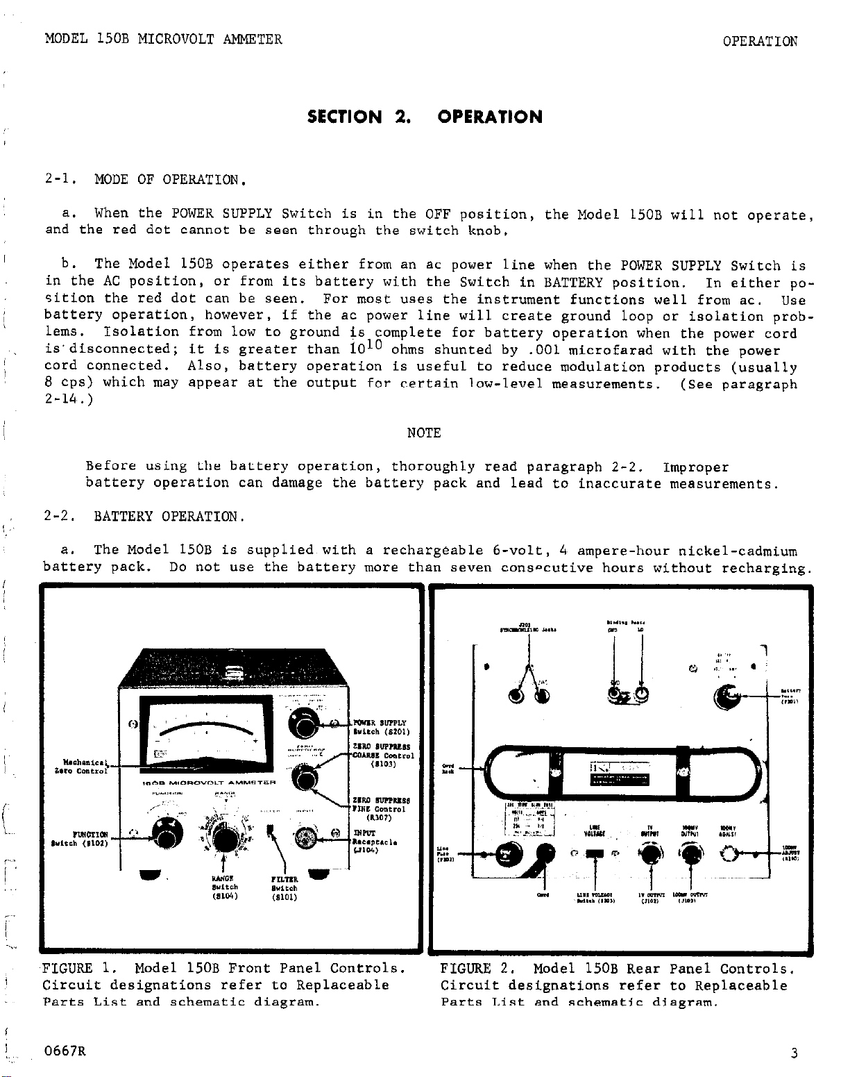
MODEL 150B MICROVOLT AMMETER
OPERATION
SECTION 2.
2-l.
and the red dot cannot be seen through the switch knob.
in the AC position, or from its battery with the Switch in BATTERY position.
sition the red dot can be seen.
battery operation, however, if the ac power line will create ground loop or isolation prob-
lems.
is'disconnected; it is greater than 101" ohms shunted by .OOl microfarad with the power
cord connected.
8 cps) which may appear at the output for certain low-level measurements. (See paragraph
2-14,.)
2-2.
MODE OF OPERATION,
a. When the POWER SUPPLY Switch is in the OFF position, the Model 150B will
b. The Model 150B operates either from an ac power line when the POWER SUPPLY Switch is
For most uses the instrument functions well from ac. use
Isolation from low to ground is complete for battery operation when the power cord
Also, battery operation is useful to reduce modulation products (usually
Before using the battery operation,
battery operation can damage the battery pack and lead to inaccurate measurements.
BATTERY OPERATION.
thoroughly read paragraph 2-2.
OPERATION
not operate,
In either po-
NOTE
Improper
The Model 150B is supplied with a rechargeable 6-volt,
battery pack. Do not use the battery more than seven consncutive hours without recharging.
4, ampere-hour nickel-cadmium
,FIGURE 1.
Circuit designations refer to Replaceable
Parts List and schematic diagram.
0667R
Model 150B Front Panel Controls.
FIGURE 2.
Circuit designations refer to Replaceable
Parts List and schematic diagram.
Model 150B Rear Panel Controls.
3
Page 8
OPERATION
..~
-.,
-.
MODEL 150B MICROVOLT AMMETER
NOTE
Permanent damage to the battery pack may occur if it is used for
secutive hours witbout recharging.
gycles is greatly reduced.
Before using the Model 150B, check the state of the
At this discharge rate, the number of recharge
more
than 8 con-
battery charge.
Check the battery charge before making a measurement. Hold the POWER SUPPLY Switch
b.
in the BATT. TEST position; the red dot will show.
the state of the battery charge directly on the meter.
In this position the Model 150B shows
The minimum acceptable charge is
a meter indication of approximately +6 on the upper meter scale.
Tine terminal voltage of a nickel-cadmium battery changes very little from full
1.
charge to almost crmplete discharge.
minal voltage will vary a few minor divisions for different batteries.
The +6 meter indication for minimum charged ter-
After a few
charge-discharge cycles, the exact value of the charged terminal voltage for any in-
dividual battery wil.1 be apparent.
Recharge the battery if needed.
2.
Otherwise, battery operation is the same as for
the ac power line operating mode; refer to paragraph 2-3.
NOTE
When the battery is used beyond its capacity, two effects are seen.
a large shift in zero offset from ac to battery operation.
Also,
There is
the power
supplies do not regulate and high ripple voltages appear at the supply outputs.
C. To recharge the battery,
SUPPLY Switch t,o AC or OFF.
connect the power cord to an ac power line.
The battery will be automatically charged in either of these
Turn the POWER
positions. The charging circuit is such that the battery cannot be overcharged.
d. It is suggested that the battery be used during the day and be recharge& at night.
Leave the instrument always connected to the ac power line; then turn the POWER SUPPLY
Switch to OFF at night.
After a fully charged
it will recharge within 16 hours.
Leaving the power cord connected has little effect on
battery is used icor
the isolation: loLo ohms with the low-ground link disconnected.
longer than eight hours,
2-3.
MICROVOLT AND NULL DETECTOR OPERATING PROCEDURES.
it may take considerably longer than 16 hours to recharge.
_ .
seven
ConseCutiVe Hours,
If the battery is used
a. Set the front panel 'controls as follows:
POWER SUPPLY Switch
RANGE Switch
FUNCTION Switch
OFF
1oooMV
INPUT R lOOK
ZERO SUPPRESS COARSE Control OFF
FILTER Switch
-IN
NOTE
Make sure rha ZERO SUPPRESS COARSE Control is OFF.
voltage is introduced,
which may cause an error in measurements.
If it is not, a suppression
See paragraph
2-5 for zero suppression.
.-
-
4
0667R
Page 9
MODEL 150B MICROVOLT AElMETER
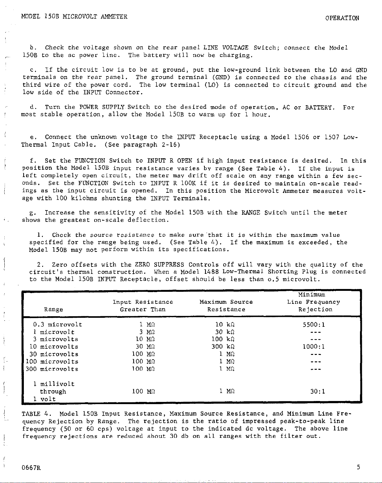
b. Check the voltage shown on the rear panel LINE VOLTAGE Switch; connect the Model
150B to the ac power line. The battery will now be charging.
If the circuit low is to be at ground, put the low-ground link between the LO and GND
c.
terminals on the rear panel. The ground terminal (GND) is connected to the chassis and the
third wire of the power cord. The low terminal (LO) is connected to circuit ground and the
low side of the INPUT Connector.
OPERATION
d. Turn the POWER SUPPLY~Switch to the desired mode of operation, AC or BATTERY.
moat stable operation, allow the Model 150B to warm up for 1 hour.
Connect the unknown voltage to the INPUT Receptacle using a Model 1506 or 1507 Low-
e.
Thermal Input Cable.
f. Set the FUNCTION Switch to INPUT R OPEN if high input resistance is desired.
position the Model 150B input resistance varies bv range (See Table 4,). If the input is
left completely open circuit,
onds.
ings as the input circuit is opened.
age with 100 kilohms shunting the INPUT Terminals.
g.
shows the greatest on-scale deflection.
specified for the range being used. (See Table 4). If the maximum is exceeded, the
Model 150B may not perform within its specifications.
circuit's thermal construction.
to the Model 15OB INPUT Receptacle, offset should be less than 0.5 microvolt.
Set the FUNCTION Switch to INPUT R 1OOK if it is desired to maintain on-scale read-
Increase the sensitivity of the Model 150B with the RANGE Switch until the meter
Check the source resistance to make sure'that it is within the maximum value
1.
Zero offsets with the ZERO SUPPRESS Controls off will vary with the quality of the
2.
(See paragraph 2-16)
the meter mav drift off scale on any range within a few sec-
In this position the Microvolt Ammeter measures volt-
When a Model 1488 Low-Thermal Shorting Plug is connected
For
In this
-~
Input Resistance
Range
0.3 microvolt
1 microvolt
3 microvolts
10 microvolts
30 microvolts
100 microvolts
300 microvolt8
1 millivolt
I
through 100 MR
TABLE 4.
quency Rejection by Range.
frequency (50 or 60 cps) voltage at input to the indicated dc voltage. The above line
frequency rejections are reduced about 30 db on all ranges with the filter out.
0667R
Model 150B Input Resistance, Maximum Source Resistance, and Minimum Line Fre-
Greater Than Resistance Rejection
1 Ma 10 kQ 55OO:l
3 Ma 30 kR ---
10 MQ 100 kR --30 Ma 300 kR 1OOO:l
00 MO 1 Ma ---
1
00 MR 1 MR ---
1
00 MO 1 MR ---
1
The rejection is the ratio of impressed peak-to-peak line
Maximum Source
1 MR
Minimum
Line Frequency
3O:l
5
Page 10
-
OPERATION
__;
I
Shifts in source resistance may also affect the zero offset, if the source resis-
3.
tance approaches the maximum value given in Table 4.
source resistances less than 10% of the maximum value.
MODEL 150B MICROVOLT AMMETER
This effect is negligible for
h. At low levels,
leads and the circuit under test.
spurious emf's may be generated simply by conta.ct between the input
These may be compensated for by the zero suppression
circuit. If possible, always leave the instrument connected, Andy adjust the zero after
estabLishing a zero reference in the apparatus under test.
For example, in bridge measure-
ments, disconnect the bridge, exciting voltage, or with a phototube, shield the tube from,
light.
2-4.
AMMETER OPERATING PROCEDURES.
the range using the RANGE Switch.
Set the FUNCTION Switch to the AMPS position.
Make sure low resistance leads are used to connect the
source to the Model 150B input to minimize input voltage drop.
rent overload on any range is 100 mii'liamperes.
put voltage drop is exceeded (see specifications),
If this is exceeded,
the current-sensing resistor may be dam-
The maximum allowable cur-
or if the maximum in-
Select
aged. The Model 150B rise time (10% to 90%) as an ammeter is less than 1 second on the 3nanoampere and higher ranges, increasing to 3 seconds on the 0.3-nanoampere range.
2-5.
ZERO SUPPRESS OPERATION.
a. Purpose:
The zero suppression circuit cancels any constant voltage in order to use
a more sensitive range to observe a superimposed signal. Stability is such that up to
100 times full scale may be suppressed. For example,
the Model 150B can measure changes
of less than one microvolt in a lOO-microvolt steady signal on its l-microvolt range.
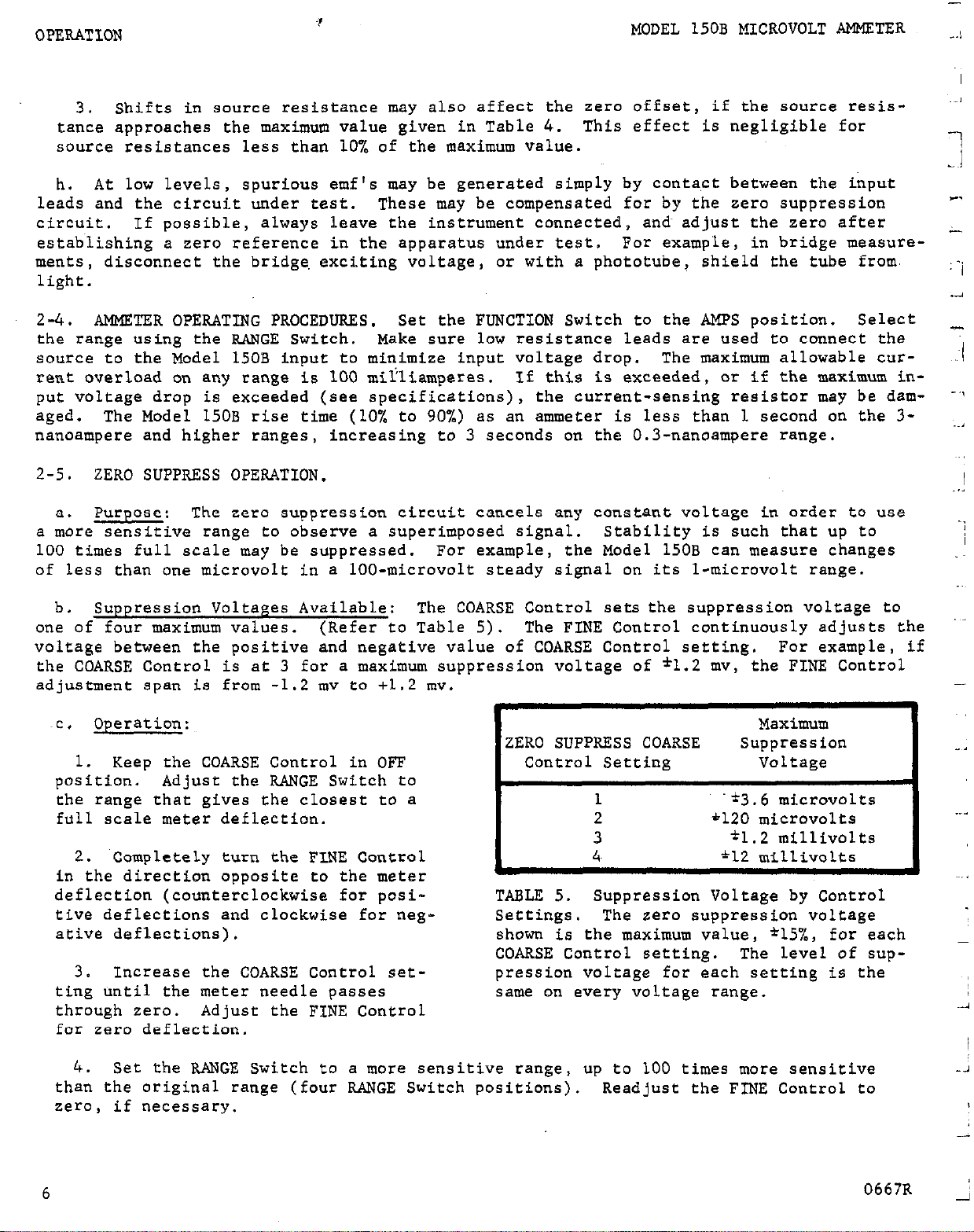
b. Suppression Voltages Available:
one of four maximum values. (Refer to Table 5).
The COARSE Control sets the suppression voltage to
The FINE Control continuously adjusts the
voltage between the positive and negative value of COARSE Control setting. For example, if
the COARSE Control is at 3 for a maximum suppression voltage of l 1.2 mv, the FINE Control
adjustment span is from -1.2 mv to +1.2 mv.
Operation:
~C.
Maximum
ZERO SUPPRESS COARSE Suppression
1.
Keep the COARSE Control in OFF
position.
Adjust the RANGE Switch to
the range that gives the closest to a
full scale meter deflection.
Control Setting Voltage
1
2
.*3.6 microvolts
*120 microvolts
3 t1.2 millivolts
2.
Completely turn the FINE Control
4.
*12 millivolts
in the direction opposite to the meter
deflection (counterclockwise for positive deflections and clockwise for negative deflections).
TABLE 5.
Settings. The zero suppression voltage
shown is the maximum value, *15%, for each
Suppression Voltage by Control
COARSE Control setting. The Level of sup-
3.
Increase the COARSE Control set-
ting until the meter needle passes
pression voltage for each setting is the
same on every voltage range.
through sero. Adjust the FINE Control
for zero deflection.
..,
-,
I
-
4.
Set the RANGE Switch to a more sensitive range,
than the original range (four RANGE Switch positions).
zero, if necessary.
6
up to 100 times more sensitive
Readjust the FINE Control to
-J
0667R _;
Page 11
MODEL 150B MICROVOLT AMMETER
OPERATION
2-6.
FILTER SWITCH.
The input filter is adjusted at the factory for 60 cps line frequency, unless 50 cps
a.
is indicated on the rear panel of the Model 150B.
b. When the FILTER Switch is at the IN position, a line frequency (Twin-Tee) filter is
used at the INPUT. With the Switch at the IN position a higher level (about 3~0 db) of 60
cps
can be tolerated at the INPUT without affecting the accuracy or the sensitivity of the
Model 150B.
Nomally ,
it is best to leave the FILTER Switch at the IN position for all
cases except where the source resistance exceeds 300 kilohms.
c. The filter has a 5-microfarad capacitor.
capacitor is in use and produces an RC time constant.
ohms or greater,
the rise time of the Model 150B is affected by the RC time constant and
When the FILTER Switch is set to IN, this
For a source resistance of 300 kil-
increases above that given in the specifications.
With the Switch set to OUT, the capacitor is not in use.
d.
If rise time is important,
set the FILTER Switch to~the OUT position for source resistances greater than 300 kilohms.
HOWeVer, with the filter out, the line frequency rejection is reduced 30 db on all ranges.
2-7. RECORDER OUTPUTS.
The Model 150B has two'recorder outputs; fl volt at up to 1 mil-
liampere and a filtered *lOO millivolts.
The *l volt, 1 milliampere output is accurate to i-l% of full scale. Output resis-
a.
tance is less than 5 ohms within the amplifier pass band.
eithef battery or ac operation.
I'f the Model 150B is used for differential measurements,
This output may be used during
do not ground the recorder connected to the output.
When recording with the 1 volt 1 milliampere output, the Keithley Model 370 Recorder
1.
offers complete compatability with the Model 150B.
This output is sufficient to drive
the Model 370 without the use of any recorder preamplifiers. The Model 370 allows maxi-
mum capability of the Model 150B.
to 1500 volts off ground.
Using the Model 370 with the Model 150B avoids interface
It has 1% linearity, 10 chart speeds and can float up
problems which may be encountered between a measuring instrument and a recorder.
The Model 370 is very easy to use with the Model 150B.
2.
All that is necessary is
connecting the two units and adjusting an easily accessible control for full-scale recorder deflection.
on the Model 150B.
an 8 cps beat may appear..
The furnished Model 3701 Input Cable mates with the output connector
On the most sensitive ranges of the Model 150B, under some conditions,
This condition can be eliminated by mounting a lOO-microfarad
capacitor across pins 14. and 17 in the back of the Model 370 Recorder.
The other recorder output is ilO0 millivolts.
b.
with servo balance recorders.
The 1OOMV ADJUST, which is a screwdriver adjust potentiom-
eter on the rear panel of the Model 150B,
millivolt span.
The resistance of this recorder output is less than 1000 ohms.
is used to adjust the 1OOMV output over a lo-
This output can be used in conjunction
The 1OOMV
output Receptacle is filtered to provide less than l/2% peak-to-peak ac voltages in the
output signal.
may be used during either ac or battery operation.
The rise time will be no less than 1 second on any range. This output
If the Model 150B is used for differ-
ential measurements, do not ground the recorder connected to the output.
2-8. SYNCHRONIZING TERMINALS.
When two or more Model 150Bs are close together,
due to the slight difference in their chopper frequencies.
All Model 150Bs have nearly the same chopper frequency.
a beat may develop between the instruments
To eliminate this interaction,
0667R
7
Page 12
OPERATION
/
I
MODEL 150B MICROVOLT AMMETER
7
.,
use the two synchronizing terminals on the rear panel of the instrument.
synchronize the chopper, frequencies.
No polarity is necessary; just connect leads from the
These terminals ~'
terminals of one Model 150B to the same terminals on an adjacent Model 150B.
2-9. DIFFERENTIAI. (FLOATING) MEASUREMENTS.
a. The Model 150B will measure the difference between two voltages, neither~ of which is
at power line ground.
It can be floated up to *400 volts off ground.
CAUTION
The instantaneous voltage between circuit low and case ground must not exceed *400
volts at any time.
If the power cord is unplugged,
case may be at any voltage.
For best results in making differential measurements, follow the steps below:
b.
The front panel controls are electrically conne,cted to the case.
and the off-ground voltage exce'eds *400 volts, the
Use necessary safety precautions.
-
1. Remove the link from the LO terminal on the rear panel.
Connect the source to the input.
2.
Make ,measurements as described in- paragraph 2-3.
The zero suppress controls may be used for differential measurements.
If power line frequency pickup is a problem, use battery operation.
3.
-
When recording from the Model 150B with the LO to GND link removed, be sure to
4.
-use a recorder which also has LO isolated from GND by a high imp&dance, and is also
capable of withstanding the necessary voltage with respect to ground.
The Keithley
Model 370 Recorder meets these requirements.
Z-10.
ACCURACY CONSIDERATIONS.
other considerations besides the instrument affect accuracy.
working with higher voltages are very important with microvolt signals.
For sensitive measurements - 10 millivolts and below -
Effects not noticeable when
The Model 150B
reads only the signal received at its input; therefore, it is important that this signal
be properly transmitted from the source. The following paragraphs indicate factors which
affect accuracy:
thermal noise,
input resistance, thermal emf's, shielding and circuit
connections.
2-11. THEIU@L NOISE.
a. The lower limit in measuring small potentials occurs when the Johnson noise, or
thermal agitation, becomes evident. The amount of noise present in the source is shown
in the following equations.
Thermal noise in any ideal resistance can be determined from the Johnson
1.
noise equation:
E2
rms
- 4kTRF Equation 1
where E,, is the rms noise voltage developed across the voltage source;
T is the temperature in degrees Kelvin;
R is the source resistance in ohms;
F is the amplifier bandwidth in cps;
k is the Boltzmann constant (1.38 x 10mz3 joules/OK).
8
0667R
Page 13
MODEL 150B MICROVOLT AMMETER OPERATION
For an ideal resistance at room temperature (300°K), equation 1 simplifies to
Erms
2. Peak-to-peak meter indications are of more interest than the rms value.
mentally, the peak-to-peak Johnson noise is about five times the rms value.
temperature, equation 2 becomes
EPP
where Epp is peak-to-peak noise voltage developed across the voltage source.
3. The Model 150B bandwidth, F, can be estimated from the response speed, tr, by:
F = 0.35/t, Equation 4
The response speed varies with the range used and the source resistance. On the l-
microvolt range when the source resistance is less than 33 kilohms, for example, the
bandwidth is greater than .07 cps.
ation is 6 seconds, so the .07-cps bandwidth is a minimum value.
b. In general,
tars, and equations 2 and 3 are nearly correct. If the source resistance is composed of
other materials, it may be necessary to include other terms in the equations to account
for flicker, l/f, and current noise over and above the thermal noise.
c. As seen in equations 2 and 3, the noise of even low resistance values becomes significant in the microvolt region. The noise in non-ideal resistors is even greater. Therefore, keep the source resistance as low as possible. Other effects of very high source
resistance are decreased response speed and added pickup of extraneous voltages.
good wirewound or low-noise metal-film resistors approximate ideal resis-
= 1.29 x 10-l' (R F)1/2
= 6.4,s x 10-l' (R F)l/2
The maximum specified response speed for this situ-
Equation 2
Experi-
At room
Equation 3
Z-12.
obtained using high feedback factors. When the source resistance exceeds the amplifier's
physical input resistance - amplifier input resistance without feedback - the feedback
is partially destroyed.
exceed the maximum source resistance listed in Table 4,.
but noise, offsets, slow response and instability may result. On the most sensitive ranges,
the maximum specified source resistance is consistent with Johnson noise considerations.
2-13.
a. Thermal emf's (thermo-electric potentials) are generated by thermal gradients be-
tween any two junctions of dissimilar metals. These can be large compared to the signals
which the Model 150B can measure.
b.
Model 150B can have some offset (paragraph 2-3).
touching the circuit, by putting a heat source near the circuit, or by a regular pattern
of instability,
INPUT RESISTANCE.
THERMAL EMF'S.
Thermal emf's can cause the following problems:
Meter instability or zero offset much higher than expected.
1.
Meter is very sensitive to ambient temperature differences.
2.
corresponding to heating and air conditioning systems or changes in sun-
light.
The Model 150B is a feedback amplifier; its input resistance is
Then the instrument may not operate properly. Normally, do not
Higher resistances can be used,
Note, though, the
This is seen by
9
Page 14
OPERATION
To minimize the drift caused by thermal emf's, use the same metal or metals having
C.
MODEL 150B MICROVOLT AMMETER
the same thermo-electric powers in the input circuit. Gold, silver and low-thermal solder
have a thermo-electric power within about to.25 pv/“C of copper. This means a temperature
inbalance of l°C between these metals would generate a thermal,emf of about 0.25 microvolt.
At the other extreme, germanium has a thermoelectric power of about 320 nv/oC, and silicon
will develop about 420 nvv/'C against copper. Standard physical handbooks contain tables
of thermoelectric powers of materials. Since the Model 150B input circuit is made of pure
copper, the best junction is copper to copper. However, copper oxide in the junction will
cause thermal emf's on the order of 100 nanovolts per oC or less. Also, differences in
processing of two pieces of copper can cause thermal emf's of up to 0.2 microvolt per "C.
The Model 1483 Kit contains all necessary equipment to make very low thermal copper crimp
joints.
d.
temperatures.
lar sources which vary temperature.
See paragraph 2-16.
Besides using similar metals, thermal emf's can be reduced by maintaining constant
Keep all circuits from open windows, fans,
air conditioning vents and simi-
Minimize thermal gradients by placing all junctions
physically close on a large heat sink. Thoroughly c,lean all copper leads before making a
connection.
Crimp together the ends of each copper wire; bolt the lugs for each connectior
point together; mount all stacks of lugs on a thick metal plate having high thermal conductivity. Thermal conductivity between the junctions and the heat sink can be kept at a high
level by using mica washers or high conductivity ceramics for electrical insulation.
e. Several other techniques will reduce the effects of thermal emf's. Use the zero suppression circuit to buckout constant voltages.
cadmium-tin low-thermal solder, such as supplied in the Model
If connections must be soldered, use only
1483 Kit.
If cadmium solder
is used for connections, make sure the soldering iron used is clean and that it has not
been used with regular solder before. Use only Rosin solder flux.
all cadmium,-soldered joints together to reduce thermal emf's.
Unlike metals - including
If possible, heat sink
regular solder - may be used and low thermal emf's obtained if a well-controlled oil bath
or a good heat sink is used.
Thermal voltages may be calculated from the thermoelectric
power of the materials in the junction and the possible temperature difference between the
junctions.
2-14.
a. Due to its narrow bandwidth and filtering,
voltages superimposed upon a dc signal at the input terminals.
SHIELDING.
the Model 150B is quite insensitive to ac
However,
ac voltages which
are large compared with the dc signal - thousands of times greater on the more sensitive
ranges - may drive the Model 150B ac amplifier into saturation, increasing the noise and
erroneously producing a dc output at the demodulator. Therefore,
the circuit should be
shielded and the shield connected to the Microvolt Ammeter ground, particularly for low-
level sources.
Improper shielding can cause the Model 150B to react in one or more of the following
b.
ways:
Needle jitter or instability,
1.
from 10% to 20% of full scale.
2. High offset (dc bias). Changing the power cord polarity or the connection between
the LO and GND terminals may affect the amount of offset.
3. Slow response time, sluggish action and/or inconsistent readings between ranges.
c. To minimize pickup, keep the voltage source and the Microvolt Ammeter away from
strong ac magnetic sources.
Connect all shields together at the low side of the input or
10
0467R
Page 15
MODEL 150B MICROVOLT AMMETER
OPERATION
at the LO terminal.
of the loop.
Therefore, minimize loop areas in the shield connections as well as the in-
The voltage induced due to magnetic flux is proportional to the area
put circuitry. Connect the shield at only one point. Run all wires in the circuit along
the same path,
so the loop area is only the small difference in position of two adjacent
wires.
Strong third harmonic magnetic fields - 180 cps for 60-cps units - may create an
d.
8-cps beat at the Microvolt Ammeter output and meter. To reduce this effect, turn off all
possible nearby sources, such as heavy-duty transformers. Remove the Model 150B and the
measuring circuit as far as possible from the magnetic field. If removal does not greatly
reduce the beat, magnetic as well as electrostatic shielding around the circuit may be
necessary. The ratio of the 8-cps amplitude to the dc output level may be reduced by
nearly 1 decade using the 1OOmv filtered output.
2-15.
OPERATING FROM SOURCE OTHER THAh' 117 VOLTS, 60 CPS.
If the ac power source is 234 volts, use a screwdriver to change the Line Voltage
a.
Switch on the back panel, Change the fuse from l/8 ampere to l/16 ampere. Use only 250-
volt MDL fuses. No other adjustment is necessary.
The Model 150B can operate satisfactorily from 60 or 50-cps sources, but the best ac
b.
reiection is achieved when the filteris set for the line freauencv.
For 50-CDS ac Dower
sources, change the two resistors in the input filter R14~7 and R14~8 (Figure 18). use
Keithley part Rl32-1273 (R147 and R14,8)
for 50 cps. Some units are, per special
order, modified at the factory for 50-cps ac
power sources. The filter in these cases is
adjusted for SO-cps,
and this fact is indi-
cated on the re.ar panel of the Model 150B.
2-16.
ACCESSORIES FOR INPUT CONNECTIONS.
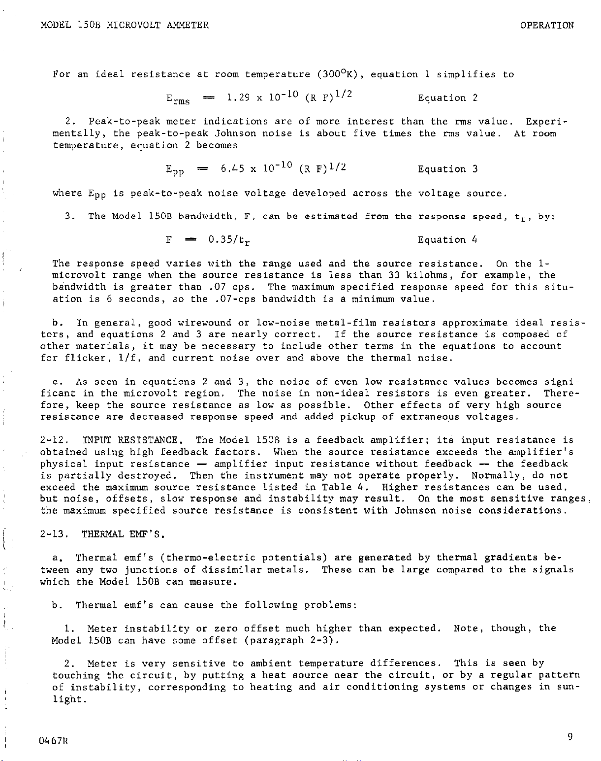
The easiest way to connect the volt-
a.
age source to the Model 150B input is with
the Model 1506 Input Cable supplied with
the instrument.
ary setups, for measurements at several
points, and when fast connections are needed.
Use the Cable for tempor-
FIGURE 3.
Cable.
Model 1506 Low-Thermal Input
The Model.1506, which has alligator clips,
connects directly to the INPUT Receptacle.
Where more permanent setups are needed,
b.
use the Model 1507 Input Cable. It is
similar to the Model 1506, except it has spade lugs instead of alligator clips.
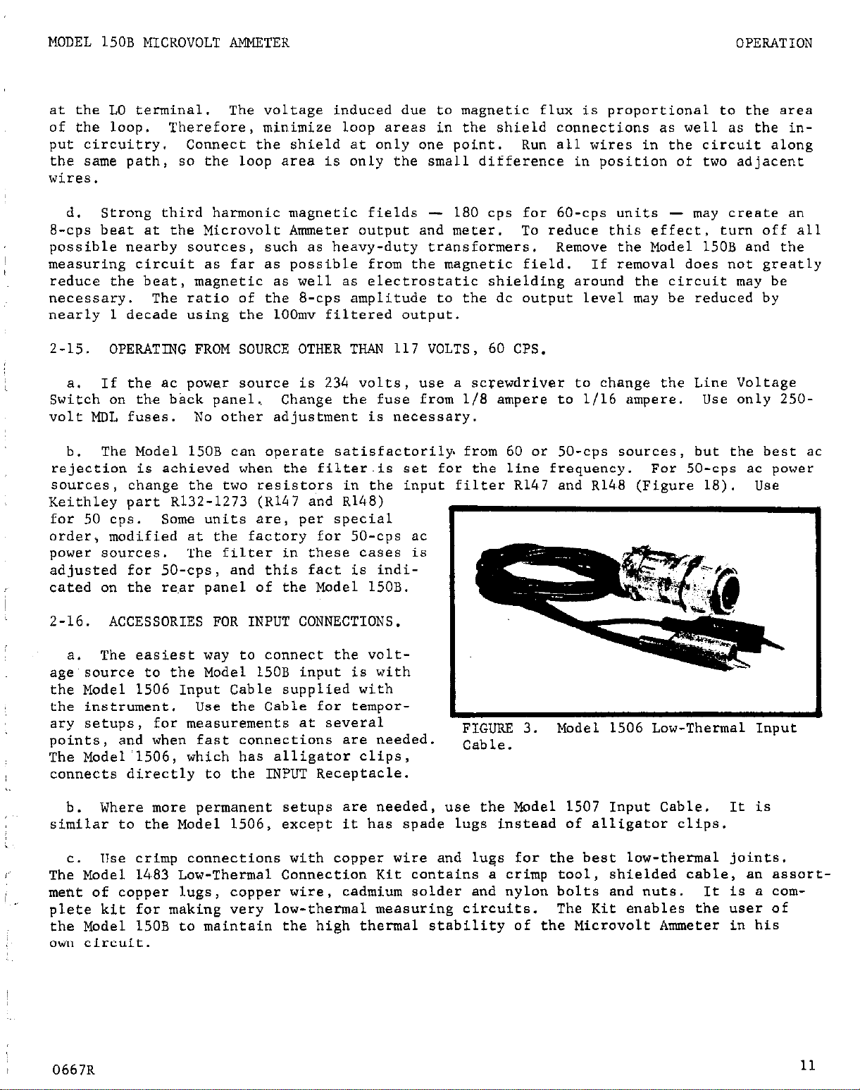
Use crimp connections with copper wire and lugs for the best low-thermal joints.
C.
The Model 14,83 Low-Thermal Connection Kit contains a crimp tool, shielded cable, an assort-
ment of copper lugs, copper wire,
cadmium solder and nylon bolts and nuts. It is *
com-
plete kit for making very low-thermal measuring circuits. The Kit enables the user of
the Model 150B to maintain the high thermal stability of the Microvolt Ammeter in his
own circuit.
0667R
11
Page 16
OPERATION
The Model 1486 male low-thermal input
d.
connector is for connecting custom-made
circuits to the Model 150B.
e. Other available accessories are:
The Model 1484 Refill Kit, which contains
replacement parts for the Model 1483; The
Model 1485 female low-thermal input con-
nector to use with the Model 1486 for
building shielded low-thermal circuits;
Model 1488 Low-Thermal Shorting Plug, which
is helpful in testing the Model 150B; Model
1489, which is a replacement nickel-cadmium
battery pack.
Model 1481 or Model 1482 Input Cable,
f.
supplied with the Keithley Models 147 and
148, may be-used with the Model 150B. The
shielding in these cables, however, is not
as good as the shielding in the Models 1506
and 1507 Input Cables.
Shielding problems
occur with the Models 1481 and 1482 Cables
at source resistances greater than 10
kilohms.
WODEL 150B MICROVOLT AMMETER
FIGDRE 4.
Model 1483 Low-Thermal
Connections Kit..
12
0667R
-
Page 17
MODEL 1508 MICROVOLT AMMETER
CIRCUIT DESCRIPTION
SECTION 3. CIRCUIT DESCRIPTION
3-1. GENERAL.
The Model 150B consists of a chopper demodulator system followed by a dc amplifier.
a.
Feedback is applied to the whole loop. (See Figure 5).
A mechanical chopper converts the dc input signal to a 94-cps signal. The ac signal
b.
is amplified, demodulated,
back network samples the signal at the output and compares it to the input.
dc amplified and applied to the meter and the output.
The dc input
signal and the feedback signal are compared in the input transformer primary.
former increases the voltage-difference signal between the two.
the difference signal.
The ac signal is then demodulated by a saturated transistor switch
The ac amplifier amplifies
and enters a dc amplifier, which has a feedback capacitor td filter out the demodulator
ripple.
feedback network.
The dc’amplifier output is connected to the meter, the output terminals and the
The feedback resistors determine full-scale range.
The zero suppress
signal is connected to the feedback point in the input circuit.
A feed-
The trans-
94 CPS CIIOPPTR DRIrn
I
I 1
FIGURE 5.
f
I
Block Diagram of Model 150B Amplifier Circuits.
LNMRTER
I I1 I
c. The power source for the Model 150B is either line voltage or the rechargeable bat-
tery .
Voltage from either’ source is applied to a regulator, then to an inverter, then to
two supplies (which provide large amounts of filtering) and a demodulator and chopper drive.
The two supplies furnish power to the amplifier circuits. There is also a battery charging
circuit to charge the battery when the line voltage is connected.
NOTE
The circuit designations referred~to in this section are for Schematic Diagrams
203503 and 20357D found at the back of the manual.’
3-2. INPUT CIRCUIT.
The dc input signal is connected through the high terminal of the INPUT Receptacle,
a.
5104, through the input filter to the center contact of the mechanical chopper, GlOl.
(see Figure 6).
The feedback signal is applied to the center tap of the input transformer,
03678
13
Page 18
CIRCUIT DESCRIPTION
._
~~_
MODEL 150B MICROVOLT AMMETER
Input
Chopper
. ”
Transformer
FIGURE 7. Model 150B Input Circuit. The dc input signal, Vin, is applied to the mechani-
cal chopper.
The feedback signal, Vf (the dc amplifier output voltage, Vo, times &he
feedback ratio, b ), is applied to the transformer primary. The signal, Vd~> stepped up
by the transformer is the difference between the two, Vd = Vin - Vf. When the dc input
signal is initially .applied to the Model 150B,
primary is entirely vin. As the output voltage rises,
a small value, vf = fin. or 4 V, = vin.
Vf is zero and the voltage across the
Vf increases and vd decreases to
Only L? I
which depends upon the RANGE and
FUNCTION Switch settings, determines the amplifier gain.
T101. The chopper alternately applies a positive and a negative square-wave signal across
each half of the primary. The magnitude of the square wave is proportional to the dif-
ference between the dc input and the feedback signal.
TlOl increases the magnitude of
this signal and applies it to the grid of tube VI.
b. The input compartment is designed to insure high thermal stability and to minimize
internal ac pickup.
1. Thermal stability is obtained in part by using only copper wire interconnections
in the input circuitry. Connections between components are made with low-thermal cad=.
mium solder.
section of the feedback loop.
Special low-thermal resistors are used in the filter and in the low-level
The switches "se standard contacts and rotors, gold
plated for low thermal emf's and high reliability.
The input compartment is shielded against magnetic and electrostatic pickup on all
2.
sides.
The wires are physically placed to maintain minimum loop area, further minimiz-
ing pickup.
C.
The feedback network is formed from the output of the dc amplifier back to the
center tap of the primary of transformer TlOl.
The RANGE Switch, S104, selects the
feedback rati.: used for each range.
3-3.
AC AMPLIFIER.
a. The ac ampiifi;?:: circuit amplifies the 94-cps difference signal which
to
the dc inpui signa,.
The signal is applied to the grid of tube Vl and amplified.
14
corresponds
0367R
Page 19

MODEL 150B MICROVOLT AMMETER
CIRCUIT DESCRIPTION
Transistor QlOl acts as a cc~nstant current source for tube Vl, with field effect transistor
Q102 providing a high impedance level following the first stage. Transistor Q103 is for
impedance matching.
justs the gain to compensate for beta variations.
by transistors QlO4 through Q107.
Potentiometer R112, between the Q103 emitter and the QlO4 base, ad-
The difference signal is then amplified
Transistors 9106 and Ql07 also form a full wave signal
for demodulation.
The tube type of Vl and the bias of Vl with transistors QlOl and Q102 are selected
b.
for low-noise operation at 94, cps.
quency to be amplified by the first stage is selected to be 94 cps (TT ADJ Controls,
A narrow bandwidth around 94 cps is provided. The fre-
Poten-
tiometers R140 and R143) by a notch filterin a feedback loop around the first stages.
3-4. DEMODULATOR.
switch demodulator.
with ripple component.
wave rectified signal.
Transistors QlO6 and QlO9 in inverted configuration form a transistor
They convert the 94,-cps wave from the ac amplifier into a dc voltage
Resistors Rl.27 and Rl28 sum the voltages from each to form a fullThe secondary of the inverter transformer, T201, furnishes a
square-wave drive for the demodulator.
3-5. DC AMPLIFIER.
a. The demodulator signal is amplified by two low-drift,
QllO and Qlll,
in differential configuration to compensate for temperature drift.
high gain silicon transistors,
Silicon
transistors Qll2 and Q113 form the second amplifier stage. Total gain is about 500.
Diode D102 limits the output current,
A feedback loop with capacitors Cl09 and Cl20 around the dc amplifier acts as an
b.
integrator, filtering the ripple component of the demodulated waveform.
capacity,
which is approximately the value of Cl09 and Cl.20 times the dc amplifier gain,
protecting output transistor 9114.
The effective
and the feedback factor (or open-loop gain) of the entire amplifier, Vl to Q114, determine
the response speed of the system.
The capacitive feedback also reduces the noise in the
amplifier outside the system bandpass.
3-6. ZERO SUPPRESSION.
The zero suppress circuit provides a regulated voltage from the
power supplies to buckout steady background potentials in the input signal. The lo-turn FINE
Control, potentiometer R307, is connected between -12 and +12 volt outputs. The rotor of
potentiometer R307 is connected to a resistive divider R187, R301, R302 and R303 in the
COARSE Switch which further divides the voltage. The suppression voltage is applied direct-
ly to the feedback resistor, RT65, whic'h acts as another divider in conjunction with R149.
3-7. POWER SUPPLIES (See Figure 7.)
The power supply for the Model 150B consists of a
regulated supply which operates from the power transformer or a rechargeable battery.
The output of this regulator feeds an inverter, two highly filtered supplies with outputs
of +12, -12 volts and a drive circuit for the chopper and demodulator. These power all
the other Model 150B circuits.
The line power, battery and battery charging circuits are controlled through the
a.
POWER SUPPLY Switch, S201.
When the switch is in AC, the battery is charged and the power
supply operates from the power transformer, T202. When the switch is in OFF, the battery
charges; all other circuits are off.
When the switch is in BATTERY, the power supply
operates from the battery; the power transformer is disconnected at its primary windings.
The regulated supply is prefiltered with a large capacitor, C211. The supply con-
b.
sists of a series regulator with a darlington pass arrangement made up of Q218, Q212 and
Q214.
Any variation across the output is referenced by resistors R234 and R238 with zener
0467R
15
Page 20

CIRCUIT DESCRIPTION
MODEL 150B 'MICROVOLT AMMETER
FIGURE 7. Block Diagram of Model 150B Power Supplies.
diode D211 and compensated for by the amplifier consisting of Q215, Q216 and Q217.
The
output of the supply is adjustable around -5 voLts.
Voltage from the regulated supply is applied to the inverter circuit.
Transistors
92:; and Q202 form a switching network to supply a square-wave voltage to transformer
T201.
The switching frequency is 94 cps,
T201 has a saturable ferrite core.
The inverter circuit supplies voltages to the two
the same as the carrier frequency. Transformer
regulated supplies and the chopper demodulator circuit.
The +12 volt supply is a highly filtered voltage taken from the secondary windings
d.
of the inverter transformer, T201. Diodes D201 and D202 furl wave rectify the signal
from the transformer.
lington configuration,
supply output.
A current limiting circuit, transistor Q205, protects the pass transistor
This signal is filtered by the RC filter, R204 and C203.
A Dar-
transistors Q203 and Q204, maintains the low-ripple voltage at the
if the output of the supply is shorted.
The -12 volt supply operates in 9 similar manner to the +12 volt supply.
e.
One secondary of the inverter transformer drives transistors Q209 and Q2LO through
f.
a phase compensating network made up of resistors R220 through R224 and capacitor C210.
This phase compensation network compensates for the chopper phase shift.
Transistors
Q209 and Q210 are alternately cut off and driven into saturation, forming a square wave
drive to the demodulator.
ary of the inverter transformer that is used to drive the demodulator.
The drive for the chopper is taken from one-half of the second-
Capacitor C213
"rounds off" the square wave to produce a more acceptable chopper drive wave form.
-..
.-
-
Page 21

MODEL 150B MICROVOLT AMMFTER
CIRCUIT DESCRIPTION
3-8.
BATTERY CHARGING CIRCIIIT.
a. The battery circuit operates when the POWER SUPPLY Switch, 5201, is in the AC or
OFF position.
b. A charging currant from transistor T20.. is applied to the battery through a half
wave rectifier and a series resistor, RZ28. A fuse is incorporated in this circuit to
protect the instrument and the battery.
Note, however,
that the battery can be damaged
if it is used far beyond its capacity. A polarity reversal of a crll may occur, causing
heavy circulating currents within the battery.
,..
1266~ 17
Page 22

MAINTENANCE MODEL
I.508
._
MICROVOLT AMMETER
.,.
,-
Instrument
Hewlett-Packard Model 200 CD
Oscillator, 5 cps to 600 kc,
*2% accuracy.
Hewlett-Packard Model 5512A
Electronic Counter, 300-kc counting
rate, 10.1% accuracy.
Keithley Instruments 1488
Low-Thermal Shorting Plug.
Keithley Instruments Model 1507
Input Cable.
Keithley Instruments Model 260
Nanovolt Source.
Keithley Instruments Model 261
Picoampere Source.
Keithley Instruments Model 370
Recorder.
Use
TT adjust and Filter adjust
calibration.
Minitor oscillator frequency.
Short Model 150B INPUT Receptacle.
Connecting cable for Model 260 and
Model 150B.
Signal source for calibrating Model
150B.
Signal source for calibrating Model
150B.
Monitor drift.
,_.
7
<~_
.-
.-
_.
.-
Keithley Instruments Model 6lOB
Check plate voltage of tube VI.
Electrometer.
Keithley Instruments Model 662
Check voltage at output terminals.
Guarded DC Differential Voltmeter,
l
O.Ol% to 1 millivolt.
RCA Model WV98B Senior Voltohmyst,
Check dc voltages throughout circuit.
11 MD input resistance, *3% accuracy,
0 to 1500 volts dc.
Tektronix Type 503 Oscilloscope, dc Check wave forms for troubleshooting
to 450 kc.
TABLE 6.
Equipment Recormsended for Troubleshooting and Calibrating the Model 150B. Use
and calibration.
these instruments or their equivalents.
18 0667R
Page 23

MODEL 150B MICROVOLT AMMETER
SECTION 4.
4-l. GENERAL.
Section 4 contains the maintenance,
a.
the Model 150B.
to maintain the instrument's specifications.
The Model 150B requires no periodic maintenance beyond the normal care required of
b.
high-quality electronic equipment.
cipal maintenance is an occasional chopper replacement. (See paragraph 4-3.) Occasional
verification of meter calibration (paragraph 4-7) should show any need for
4-2.
Microvolt Ammeter.
ments which meet the specifications.
the components listed in Table 7.
List are purchased only from Keithley Instruments or its distribtitors.
4-3. MECHANICAL CHOPPER REPLACEMENT.
PARTS REPLACEMENT,
a. The Replaceable Parts List in Section 6 describes the electrical components of the
It is recommended these procedures be followed as closely as possible
Components operate well below maximum ratings. Prin-
Replace components only as necessary, and use only reliable replace-
The Model 150B uses no special critical parts except
Make sure parts coded 80164 in the Replaceable Parts
MAINTENANCE
troubleshooting and calibration procedures for
adjustment.
The mechanical chopper is designed for long life.
a.
it will eventually wear and become noisy.
~em0~1 Procedures.
b.
Disconnect the chopper drive coil at connector 5105 (Figure 11).
1.
the chopper lugs from the studs mounted on the bottom of the input compartment.
Remove the four mounting screws from the bottom of the input compartment. Remove
2.
the old chopper.
Replacement Procedures.
c.
Mount the chopper with the four furnished screws.
1.
!
Battery pack assembly
Mechanical chopper assembly and input connector
assembly (See paragraph 4.-3.) GlOl & J105
Input transformer assembly
Dress the leads and draw the lugs down on the studs.
2.
component Desig.
At this point, replacement is necessary.
However, since it is mechanical,
Carefully remove
Circuit
BT201
TlOl
Keithley
Part No.
Model 1489
20139B
20137B
.
.
TABLE 7.
the proper lead length.
0667R
Model 150B Pre-assembled Components.
These parts have lugs crimped on them and
Use only Keithley parts for replacement.
19
Page 24

MAINTENANCE
MODEL 150B MICROVOLT AMMETER
Connect
3.
4. Check the instrument for proper operation.
the chopper drive coil at connector JlO5.
Follow paragraph 4-8, subparagraph b,
steps 1, 2 and 3.
4-4.
TROUBLESHOOTING.
The following procedures give instructions for repairing troubles which might occur
a.
in the Model 150B. Use these procedures to troubleshoot and use only specified replacement
parts.
readily Located or repaired,
b.
checking out the power supply and amplifier circuits.
Table 6 lists equipment recomsrended for troubleshooting._ If the trouble cannot be
contact Kqithley Instruments or your Keithley field engineer.
Paragraphs 4-6, 4-7 and 4-8 give step-by-step procedures for troubleshooting and
Follow these in the order given.
Tables 9 and 12 are troubleshooting tables for these circuits. Also refer to Section 3 to
find the more crucial components and to determine their function. The Schematic Diagrams,
203503, and 20357D, contain the voltages at certain points in the circuit, measured with
a Model WV98B Voltohmyst.
NOTE
Before troubleshooting inside the Model 150B, check the external circuits (paragraph 4-5). Always check out the power supply circuit before touching the ampli-
fier circuits.
The amplifier circuits often appear faulty only because of a de-
fect in the power supply.
.-
.-
4-5.
PRELIMINARY TROUBLESHOOTING PROCEDURES.
a. Before troubleshooting, check the outside circuits to the Model 150B. Isolate the
Microvolt Aaraeter from all external effects:
1.
Disconnect all outside circuits from the INPUT and OUTPUT Receptacles, and CND
and LO terminals.
Connect a low-thermal short across the INPUT Receptacle.
2.
The best connector is a
Model 1488 Low-Thermal Shorting Plug. The next best is a Model 1506 Input Cable with
the clips connected together or the Model 1507 Input Cable with the .lugs connected to-
gether. Keep the cable as far as possible from ac sources, and avoid a loop where the
alligator clips or lugs are connected.
3. Set the ZERO SUPPRESS COARSE Control to OFF.
b.
If the battery charge is acceptable (paragraph 2-2), set the POWER SUPPLY Switch to
BATTERY.
Disconnect the power cord from the power Line. Battery operation eliminates
many ground-Loop connection problems with the test equipment.
c.
If ac operation is used, check the Line Voltage Switch for correct position and the
Fuse for correct rating.
4-6.
CHECK OUT AND CALIBRATION PROCEDURES.
a. TO ascertain whether the Model 15OB is operating
of the voltage ranges and current ranges,
20
properly, perform a-~ accuracy check
0667R
Page 25

MODEL 150B MICROVOLT AMMETER
MAINTENANCE
1. To check the accuracy of the voltage ranges,
2-3.
150B using the 1507 Input Cable.
a nine-tenths full-scale signal with the Model 260 (i.e.
the 10 microvolt range; 27 microvolt signal for the ~Omicrovolt range, etc.). Check
each range for both positive and negative polarity. The meter accuracy of the Model 150B
is specified to be f2% of full scale exclusive of noise and drift.
2-4,. Use the Model 261 as the current source and connect the Model 261 to the Model 150B
using the 1507 Input Cable.
nine-tenths full-scale signal with the Model 261 (i.e.
10 nanoampere range; 27 nanoampere input signal on-tKe 30 nanoampere range, etc.),
each range for both positive and negative polarity.
is specified to be “3% of full scale exclusive of noise and drift.
calibration (paragraph.4,-7~).
to be within specification, check the indicated resistors in Table 11.
b. The following procedures give the steps to check out and calibrate the Model 150B
circuits.
shooting table.
Table 6.
Use the Model 260 as the voltage source and connect the Model 260 to the Model
Check each voltage range on the Model 1508 by applying
2. To check the accuracy of the current ranges,
Check each current range on the Model 150B by applying a
3. If any range. fails to be within specifications, check to see if the meter is in
If the meter is in calibration and any range still fails
If a circuit fails to check out at any point, refer to the circuit’s trouble-
Continue as Long as the points check out. Use the equipment listed in
follow the procedures of paragraph
9 microvolt input signal for
follow the procedures of paragraph
9 nanoampere input signal for the
Check
The meter accuracy of the Model 150B
c. Procedures are given for the power supply and amplifier circuits.
principal adjustments to bring the instrument within specifications.
d. If the Model 150B is not within specifications after performing these checks and
calibrations, return the unit to Keithley Instruments for further checkout, or follow the
troubleshooting procedures to find the fault.
I
VL Bias adjust
Gain control
TT adjust
Filter adjust
Meter Cal.
Frequency adjust
Current Coma. adiust
TABLE 8.
picturing the location,
Make sure the power supply circuit is operating correctly before checking the
amplifiers.
taken out of ourder,
Control
Model L50B Internal Controls.
All circuits depend upon properly functioning power supplies. If
Circuit
Desig.
R107 LO 4-7, 4,-8
R112 15 4-8
Rl4,O and R14,3 15 4-8
~14,6 18 4-8
R193 17 4-7
R235 13 4-7
R304, 10 4-7
The table lists all the controls, the figure
and the paragraph describing the adjustment.
NOTE
the resulting adjustment may be faulty.
Fig.
Ref.
These cover the
Refer to
Paragraph
0667~
21
Page 26

MAINTENANCE
-
MODEL 150B MICROVOLT AMMETER
TROUBLE
No voltage.at the blat'
and white wire attache1
to la$t pin before
strdon S103 (point G
Fix. 10).
Irregular wave form at
pin 8 or 9 (Fig. 8).
Incorrect 1-12 volt
supply voltage, or
ligh ripp,le on this
SUPPlY.
PROBABLE CAUSE
k
Blown fuse.
i
II209 or D210 open.
Regulator circuit not
functioning nomally.
I
Check for shorted transformer T202
or wiring;
I
Check components; replace if faulty
I
Refer to Section 3 to determine the
components in the regulator circuit.
SOLUTION
then replace fuse.
Check these components and replace
if faulty.
Defective Q203 and/or
Check components; replace if faulty.
Q204
Defective C203 and/or
Check components;
replace if faulty.
c204
-5 volt regulator
Change the value of R204; increase the
not supplying enough value if the t12 output is low; devoltage to inverter
for 94 cps.
crease it (not below 3.9 kR) if the +l
output is high.
Incorrect -12 volt
supply voltage, or
Defective Q207 and/or
Q208
Check components;
replace if faulty.
ligh ripple on this
'upply.
Defective
c209
-5 volt regulator not
Check and/or
components;
replace if faulty.
I
Change the value of R219; increase the
supplying enough volt- value if the -12 output is low; deage to inverter for
94 cps.
w.3 9.
4-9.
Troubleshooting Table for
Power
SUPP
POWER SUPPLY CHECK OUT AND CALIBRATION.
‘1Y.
a. All circuits depend upon the -5 volt regulated supply.
crease it (not below 3.9 kR) if the -1
output is high.
This supply drives the in-
verter transformer which, in turn, supplies the -12 and cl2 volt outputs.
-5 volt supply must be operating correctly before further checks are made.
suppLy fails to check out at any point, refer to Table 9.
After clearing the trouble,
continue the check.
Therefore, the
If the power
Procedures for Checking Regulated Power Supplies.
b.
Connect the Model 1488 Low-Thermal Shorting Plug to the INPUT.
1.
controls as follows:
22
Set the Model 150B -
0667R
:
Page 27

MODEL 150B MICROVOLT AMMETER
POWER SUPPLY Switch OFF
RANGE Switch 1 MICROVOLT
FUNCTION Switch INPUT R OPEN
ZERO SUPPRESS COARSE Control OFF
Line Voltage Switch Set to line voltage
FILTER Switch
Turn the FREQ ADJ Potentiometer, R235 (Figure 13) and Vl BIAS Potentiometer, R107
2.
(Figure 10) completely counterclockwise.
This ensures that the tube in the first stage
IN
and the chopper will not be damaged.
Plug in the power cord.
3.
4,. Measure the voltage at the red wire on the POWER SUPPLY Switch front deck. It
should be -11 volts dc *2 vdc.
MAINTENANCE
Turn the POWER SUPPLY Switch to AC.
5.
Use the Type 503 Oscilloscope to check the
wave form at pin 8 or 9 of connector 5201 on the bottom of PC-120 (Figure 11). Wave
form should look like Figure 8.
The dc voltage at pin 8 or 9 should be -5 volts *0.3 vdc.
a)
This voltage will be
present at pin 8 or,9 if the chopper frequency is 94 cps.
b) Check the chopper frequency by connecting the Type 503 Oscilloscope differential-
ly at pins A and D on connector X05 (Figure 11).
with the Model 5512A Electronic Counter set at 94 cps.
Measure the oscillator frequency
Connect the oscillator to the
horizontal channel of the Type 503 Oscilloscope and obtain a lissajous pattern. The
wave form of the chopper drive should resemble that in Figure 9.
FIGLJRE 8.
Correct -5v Regulated Supply
Wave Form at Pin 8 or 9 of Connector 5201.
See paragraph 4-7.
Form was obtained on
the 1 pv range with the FILTER Switch set
The
to IN.
scale is 0,2v/cm verticle, 2
msec/cm horizontal.
0667R
FIGURE 9.
at Pins A and D of 5105.
Correct Chopper Drive Wave Form
See paragraph
4-7. Form was obtained on the 1 NV range
with the FILTER Switch set to IN.
The
scale is 5v/cm vertical, 2 mseclcm horizontal.
23
Page 28

MAINTENANCE
T
~'
..,
._
..~
Measure the signal levels and ripple with respect to low of the +12 and -12 volt
6.
supplies. Table 10 gives the values.
MODEL 150B MICROVOLT AMMETER
a) To measure the +12 volt supply,
connector 5201, Figure 11.
b) To measure the-12 volt supply,
connector 5201, Figure 11.
c) To find the ripple on the supplies connect the Type 503 Oscilloscope to pin 19
or 6. The ripple should be less than 2 mv peak-to-peak.
Regulated
Power
SUPPlY
+12 volt pin 19, 5201 11 to 12.5 1;5 850 *lOO
-12 volt p'in 6, 5201 11 to 12.5 2.0 460 *70
TABLE 10.
c. Meter Noise Check.
Model 15OB input with the Model 1488 Shorting Plug or some other suitable device.
the meter noise.
not, then possible sources of noise are transistor QlOl, tube Vl, the chopper, power sup-
PlY,
and cadmium solder joints.
Signal Level, Maximum Ripple and Resistance for Regulated Power Supplies.
Test Point, Signal Level;
Figure 11 Volts dc
Set the Model 150B RANGE Switch to 0.3 MICROVOLT.
The meter noise should be less than 25 nanovolts peak-to-peak.
connect the Model WV98B Voltmeter at pin 19 of
connect the Model WV98B Voltmeter ta pin 6 of
Maximum Ripple, Resistance
Millivolts to Ground,
Peak-to-Peak
Ohms
Short the
Check
If it is
-
d. Meter Calibration.
Set the Model 150B front panel controls as follows:
1.
POWER SUPPLY Switch
RANGE Switch 100 MICROVOLTS
FUNCTION Switch
ZERO SUPPRESS COARSE Control OFF
ZERO SUPPRESS FINE Control
FILTER Switch IN
2. Short the Model 150B input with the Keithley Model 1488 Shorting Plug or s~ome
other suitable device.
Zero the meter with the Mechanical Zero Control.
3.
4. Turn the POWER SUPPLY Switch to ON and set the ZERO SUPPRESS Control to position 2.
5. Adjust the Model 15OB 1V Output to within fO.l% of full scale as read on the
Keithley Model 662 Differential Voltmeter.
6. Adjust the Meter Calibration potentiometer (Rl93, Figure 17) for a reading of 10
on the Model 150B meter scale.
OFF
VOLTS (either position)
Approximately-centered
24
e.
Current Compensation Calibration.
0667R
Page 29

MODEL 150B MICROVOLT AMMETER
1. Set the Model 150B front panel controls as follows:
MAINTENANCE
POWER SUPPLY Switch
OFF
RANGE Switch 10 MICROVOLTS
FUNCTION Switch
ZERO SUPPRESS COARSE Control
VOLTS, INPUT R 1OOK
OFF
ZERO SUPPRESS FINE Control Approximately centered
FILTER Switch
IN
2. Short the Model 150B input with the Keithley Model 1488 Shorting Plug or some
other suitable device.
Turn the POWER SUPPLY Switch to ON,
3.
Allow the Model 150B to warm up for 10
minutes and reach thermal equilibrium.
4. Zero the Model 150B using the ZERO SUPPRESS Controls.
Remove the short from the input.
5.
Adjust the Current Compensation Adjust (R304,, Figure 10) for null. A few tenths
6.
of a microvolt instability is to be expected.$
4-8. AMPLIFIER CHECK OUT AND CALIBRATION.
The check cut and calibration of the amplifier circuits is divided into these parts:
a.
operational check, gain calibration,
dtift verification.
The operational check does not have to be followed by gain calibration.
Use this to check the Model 150B operation.
point,
refer to Table 12. After clearing the trouble, continue the check.
TT Adjust calibration, Filter Adjust calibration and
If the amplifiers fail to check out at any
NOTE
If
Check the power supply circuits before adjusting the amplifiers.
changes are made,
Operational Check Procedures.
b.
Connect the Model 14,88 Low-Thermal Shorting Plug to the INPUT RECEPTACLE.
1.
the amplifier circuit may need recalibration.
extensive
Set the
front panel controls as follows:
POWER SUPPLY Switch AC
RANGE Switch 1 MICROVOLT
FUNCTION switch
INPUT R OPEN
ZERO SUPPRESS COARSE Control OFF
ZERO SUPPRESS FINE Control
FILTER Switch
On the l-microvolt range, the meter offset should be less than 0.5 microvolt (50%
2.
of full scale).
Connect the Model 610B Electrometer to'the plate of tube Vl (point E, Figure 11).
3.
It may be higher if the shorting plug (Model 1488) is not used.
Adjust the Vl BIAS Potentiometer (R107,
*0.1 volt.
the Vl BIAS Potentiometer,
If the plate voltage is high and cannot be adjusted down to 7 volts with
then decrease the value of resistor R102;
Figure 10) until the Model 610B reads 7 volts
Approximately centered
IN
If the plate vol-
tage is low and cannot be adjusted up to 7 volts with the Vl BIAS Potentiometer, then
0667R
25
Page 30

MAINTENANCE
_-
MODEL 150B MICROVOLT AMMETER
increase the value of
Remove the Model 1488 Siwrting Plug and leave the Model 150B input open. Set the
4.
FUNCTION Switch to ;I?;PUT R 100%.
1v OUTPUT.
Set the oscilloscope amplifier to dc coupling, 0.2 volt/cm, time base to 1
second/cm. Set the Model .!5OB LO the 3-microvolt range.
Control to 1 and adjust the
reli3tor
X102. Disconnect the Model 610B.
Connect the Type 503 Oscilloscope to the Model 15OB
Set the ZERO SUPPRESS COARSE
ZERO SUPPRESS FINE Control to obtain a 3-microvolt signal.
The response time (from 10% t.3 90% of final value) should be approximately 6 seconds.
Adjust Gain Control potenriometer Rl12 (Figure 15) for this value.
c. Gain Calibration Procedures.
1. Connect the Model 260 Source to the Model 150B input with the Model 1507 Input
Cable.
Connect the Model 662 Differential Voltmeter to the Model 150B 1V OUTPUT Receptacle.
2.
Before turning the Model 260 POLARITY Switch to + or -, adjust the ZERO SUPPRESS
3.
Controls for zero output at the output terminals.
Set the Model 662 to the 5-volt range.
Use the Model 662 to determine the zero output.
For a given full-scale input signal, measure the output voltage. Check each range
4,.
and rezero the output using the ZERO SUPPRESS Controls before each check. The output
should be 1 volt dc *l% for all ranges. If for any range the output is not 1 volt *l%,
refer to Table 11 and check the resistors for that range.
Replace any faulty resistor.
7
.
d. TT Adjust Calibration.
1. Set the Model 150B front panel controls as follows:
POWER SUPPLY Switch
OFF
RANGE Switch 1 MICROVOLT
,FUNCTION Switch
VOLTS (either position)
ZERO SUPPRESS COARSE Control OFF
ZERO SUPPRESS FINE Control
Approximately centered
FILTER Switch IN
Apply 10 volts peak-to-peak to the input of
2.
the 94 cps filter (pin 3 to pin 1 of
PC-119, Figure 15) with the Model 200CD Oscillator.
Adjust TT ADJ potentiometers R140 and R143 (figure 15) for minimum signal at the
3.
output, pin 6 of PC-119.
Monitor the output signal with the Model 503 Oscilloscope. The
output signal should be about 25O:l less than the input, typically 40 mv or less, and
contain very few 94 cps voltages.
Filter Adjust Calibration.
e.
Keep the Model 15OB front panel controls the same as in subparagraph d.
1.
1
Apply 10 volts peak-to-peak,
2.
60 cps (or 50 cps if designated on rear panel) to the
Model 1508 INPUT Receptacle with the Model 200CD Oscillator.
Adjust FILTER ADJ potentiometer R14.6 (Figure 18) for minimum voltage at the output
3.
of the filter (junction of resistor R14.8 to low).
Monitor the output with the Model 503
26 0667B
Page 31

MODEL 150B MICROVOLT AMMETER MAINTENANCE
Voltage Resistors used
RANGE
0.3 p"
1 K"
3 I-rv
10 I.r" Rl64, R165, R167, R170
30 K"
100 pv
300 WV R164, R165, R167, R173 300 *a
1 rn" R165, R168
3 rn" R165, R169
10 mv R165, R170 10 pia R165, R168, R181
30 Ill" R165, R171
100 rn" Rl65, R172 100 va
300 ln" R165, R1~73
IV R165 1000 pa
TABLE 11. Range Checkout.
Oscilloscope.
peak or less. The output may still contain some live frequency signal.
Drift Verification.
f.
put with the Model 1488 Low-Thermal Shorting Plug.
0.3 MICROVOLT.
the drift should be less than 0.1 microvolt per 24 hours.
tive of a faulty battery.
R164 through Rl67
R164, R165, R167, R168 1 *a
~164, R165, R167, R169 3 na
~164, R165, R167, R171
R164, R165, R167, R172
in RANGE Switch
If any ranges fail,
The filter rejection ratio should be about 300:1, typical1 30 mv peak-to-
Make sure the Model 150B mver is on. Short the Model 150B in-
Connect the Model 150B to the Model 370 Recorder.
current
RANGE
0.3 na R172, ~164, R165, R167, R174
Rl72, R164, R165, R167, R175
Rl72, R164, R165, R167, R176
10 na
30 *a
100 na
1 w
3 w
30 I.La R165, R168, R182
300 pa Rl65, R168, Rl84
check the listed resistors.
Set the Model 150B RANGE Switch to
R172, ~164, R165, R167, R177
Rl72, Rl64, R165, R167, R178
R172, Rl64, Rl65, R167, R179
R172, Rl64, R165, R167, R180
R165, Rl68, RI.79
R165, R168, R180
R165, R168, R183
R165, R168, Rl85
Excessive drift may be indica-
Resistors used
in RANGE Switch
After a l-hour warm-up
0667R
27
Page 32

High zero offset
-.
I
Short in feedback network. Make sure lugs do not touch each other o
Random zero drift, one hundreds
of nanovolts or more, somettmes
reduced if the cabinet 1s slapped. Response speed 1s within
specification.
t very temperature
sensitive.
esponse spee
possibly offset also high.
Cannot adjust to specifications
with R112.
OOK across the input,
Noisy chopper. Replace chopper; see paragraph 4-3.
Contaminated
INPUT Receptacle, Clean INPUT Receptacle with
shorting plug, or connection
in input compartment.
Low ac amplifier gain,
due to
bad active element.
If contamination goes below
plated surface, replace connector. Clean
Set to l-microvolt range, ZERO SUPPRESS
COARSE to 1, FINE to an easfly readable
non-metallic
With oscilloscope, check for
square wave at Vl grid, and sine wave at
input and output of each succeeding stage
Reduce zero suppression as necessary to
revent saturation. Check dc voltages,
schematic.
see
TABLE 12 (Sheet 1).
Amplifier Troubleshooting Table.
This table assumes that the Model 1508 has a Model 1488
Shorting Plug on the input, and that only test instruments are connected to it.
I
Page 33

TROUBLE PROBABLE CAUSE
SOLUTION
Response speed very slow,
Low gain in dc amplifier.
Unsolder and lift one end of R127, Rl28
possibly offset also high. and clO9. See points M and N, Figure 15.
Cannot adjust to specifications with R112.
Apply 1 to 1OOmv to base of QllO to zero
meter. Change input by 1 millivolt; out-
put should shift 0.5 to 1 volt. If not
or if more than 1OOmv is required to zero
check,transistors, beginning with QllO ar
Qlll.
QllO and Qlll are matched for off-
set. Replace only with parts purchased
from'Keithley.
Leaky or shorted Cl09 and/or
Check; replace if faulty.
c120.
Demodulator does not "clamp"
during one-half cycle.
Defective 9108, 9109, QZOV Check for square wave
at
collector of
or Q210. Q209 and Q210 and base of Q108 and QlOV.
Replace faulty components.
All microvolt ranges out of R164 or R165 out of tolerance.
-Check resistors; replace if faulty.
calibration. The millivolt
ranges are good.
All ranges are out of cali- R165 out of tolerance. Check resistor; replace if faulty.
bration.
One range out of calibration.
Corresponding resistor in Check resistor; replace if faulty.
Table 11 out of tolerance.
When connected in measuring Too much 60 cps at input.
circuit, meter needle oscillates
in ac and/or battery operation,
Reduce 60 cps appearing at the input by
shielding and grounding as described in
paragraph 2-14,.
even with filter in.
TABLE 12 (Sheet 2). Amplifier Troubleshooting Table. This table assumes that the Model 1508 has R Model 1488
Shorting Plug on the input,
and that only test instruments are connected to it.
Page 34

MODEL 150B MICROVOLT AMMETER
!Fiqa. 1$&l:) jFiZS. 14,515)
FIGURE 10.
Top View of the Model 15OB Chassis.
Front panel faces right.
components, printed circuits and switches is shown.
schematic diagrams for circuit designations.
Figure 11 shows the bottom view.
30
Location of
Refer to Replaceable Parts List and
0667R
Page 35

MODEL 150B MICROVOLT AMMETER
FIGURE 11.
Bottom
View of the Model 150B Chassis.
components, printed circuits,
switches and test points is shown.
Front panel faces down.
parts List and schematic diagram for circuit designations.
0667R
Location of
Refer to Replaceable
Figure 10 shows the top view.
31
Page 36

MAINTENANCE MODEL 1508 MICROVOLT AMMETER
Q216 cmi
FIGURE 12.
c21:
Capacitor, Diode and Transistor Locations~ on PC-121.
Refer to Figure 13 for resistor locations.
izo9
32
FIGURE 13.
capacitor,
Resistor Locations on PC-121. Refer to Figure 12 for
diode and transistor locations.
0667R
Page 37

MODEL 150B MICROVOLT AMMETER
MAINTENANCE
FIGURE 14.
Capacitor, Diode
and Transistor Locations on
PC-119.
Refer to Figure 15
for resistor locations and
test points M and N.
FIGURE 15.
Resistor and' Test
Point Locations on PC-119:
Refer to Figure 14. for capa-
citor, diode and transistor
locations.
0667R
33
Page 38

MAINTENANCE
D202-
MODEL 150B MICROVOLT AMMETER
FIGURE 16. Capacitor,
17 for resistor locations.
Connector and Diode Locations in PC-120. Refer to Figure
FIGURE 17.
Resistor Locations in PC-120.
connector and diode locations.
34
Refer to Figure 16 for capacitor,
Ob67R
Page 39

MODEL 150B MICROVOLT AMMETER
MAINTENANCE
FIGURE 18.
I
Component Locations on PC-118.
35
Page 40

Page 41

MODEL 150B MICROVOLT AMMETER
ACCESSORIES
SECTION 5.
5-1.
dimensions are 7 inches high x 19 inches wide x 10 inches deep.
converts to half-rack size,
screws at the bottom of each side.
Attach in this order: cover (Z),
adapter (g), and chassis connecting plate (3).
Use the 10 inch size with the Model 150B. Use the 13-inch size for 13-inch deep Keithley
instruments.
for the lo-inch cover.
I
I
MODEL 4.006 RACK MOUNTING KIT.
The Model 4,006 Kit converts the Model 150B from a bench model to rack mounting. Rack
a.
and the Kit contains a half-rack adapter panel.
Procedures. Remove the wrap-around cover on the Model 150B by removing the two corner
b.
Add the rack mounting parts as shown in Figure 19.
rack angle (5), panel support angle (7), rack panel
c. Notice that the cover assembly comes in two sizes, a 13-inch size and a lo-inch size.
The rest of the procedure for the 13-inch size is the same as given above
Item Keithley
(See Fig. 19) Description Part No.
1
2
3
4.
5
6
7
8
Cover Assembly (13 inch)
Cover Assembly (10 inch)
Chassis Connecting Plate
Screw,
Rack Angle
Screw, slotted, #lo x l/2
Panel Support Angle
Rack Adapter Panel
round head, hex socket, /ilO x l/2
ACCESSORIES
The Microvolt Ammeter
Quantity
20015B
200160
191548
----
1914.7B
----
19157A
19158A
TABLE 13. Parts List for Keithley Model 4006 Rack Mounting Kit.
5-2. MODEL 4007 DUAL RACK MOUNTING KIT
The Model 4.007 Kit converts the Model 150B to rack mounting.
a.
two lo-inch deep instruments, one each lo-inch deep instrument and 13-inch deep instrument,
or two 13-inch deep instruments. The Model 150B is a lo-inch deep instrument. Dimensions
of the Kit are 7 inches high x 19 inches wide x 10 or 13 inches deep.
Procedures. Remove the wrap-around cover on each instrument by removing the two
b.
corner screws at the bottom of each side.
Figure 20. Attach as follows when rack adapting two lo-inch instruments or two 13-inch
instruments:
chassis connecting plate (3).
instrument and one lo-inch deep instrument:
bracket (E),
0667~
cover (1 or 2), two rack angles (5),
Attach as follows when rack adapting one 13-inch deep
chassis connecting plate (7) and chassis connecting plate (3).
Assemble the rack mounting parts as shown in
chassis connecting plate (7), and
cover (1 or 2), two rack angles (5), zee
The Kit will contain
37
Page 42

ACCESSORIES
MODEL 150B MICROVOLT AMMETER
item 6
FIGURE 19.
Exploded View of Keithley Model 4,006 Rack Mounting Kit. Refer to Table 13
for parts List.
Item
(See Figure 20)
Description Part No.
1 Cover (13 inch) 19059c 2
2 Cover (10 inch) 19152B 2
3 Chassis Connecting Plate 19154.A 1
4 Screw, round head, hex socket, 810 x l/2 ---- 8
5 Rack Angle 19147B 2
6 Screw, slotted, i/10 x l/2 ---- 4
7 Chassis Connecting Plate 19700A 1
a Zee Bracket
TABLE 14.
Parts List for Keithley Model 4007 Dual Rack Mounting Kit. Two extra covers
are included in kit (see paragraph S-2).
Keithley
19167A
Quantity
1
38
0667~
Page 43

MODEL 150B MICROVOLT AMMETER
A"
I"
+- item 1
ACCESSORIES
item 7 -
\ item 4,
---_-- ^^ - . . . _..
FLti”Kls L”.
&xpLoaea view or KelcnLey MooeL quvI UuaL KacK Mounrmg K1C.
7 . . . . . 1 ., * .
I_,.-.. -.. . . . . _... ..,
wrer to
Table 14, for parts list.
5-3. MODEL 370 RECORDER.
a.. The Model 370 Recorder is uniquely compatible with the Model 150B as well as other
Keithley microvoltmeters,
electrometers and picoammeters.
The Recorder is a high quality
economical instrument that epitomizes the performance of the Model 150B, and any other
Keithley instrument,
even 'in the most critical applications.
The Model 370 can be used with
the Model 150B to record dc potentials and currents over the Model 150B's entire r.snge.
b. The Model 150B has the output necessary to drive the Recorder directly (1 volt,
1 milliampere),
volts off ground,
thus eliminating the need for a pre-amplifier.
enabling the Model 150B to be used to its specified off-ground voltage.
Th.e Recorder is specially shielded to avoid pickup of extraneous signals.
time of the Model 370 Recorder is 0.5 second; linearity is fl% of full scale.
speeds
controls.
self-priming inking system.
- from 314, inch per hour to 12 inches per minute The 6-inch chart has a rectilinear presentation.
Chart paper and ink refills are easy to install.
The Model 370 floats *500
The response
Ten chart
are selectable with front panel
The Model 370 Recorder has a
c. The Model 370 is very easy to use with the 'Model 15OB. Just connect the Model 150B's
1V OUTPUT Receptacle to the Model 370 with the furnished 3701 Input Cable and adjust an
0667R
39
Page 44

ACCESSORIES
MODEL 150B MICROVOLT AMMETER
easily accessible control for full-scale recorder deflection.
of the Model 150B, under some conditions, an 8-cps beat may appear.
On the most sensitive ranges
This condition can be
eliminated by mounting a one microfarad capacitor across pins 14, and 17 in the back of the
ode1 370 Recorder.
IGURE 21.
Especially Designed for use with Keithley Microvoltmeters and Other Instruments.
Maximum Recording Convenience is Obtained Using the Keithley Model 370,
The Model
370 can be directly connected to the,Model 1508 l-volt output with the Recorder's accessory
cable.
Response time, floating capability and other specifications of the Model 370 Re-
corder are completely compatible with those of the Modal 15OB Microvolt Ammeter.
4.0
0667R
Page 45

MODEL 150B MICROVOLT AMMETER
REPLACEABLE PARTS
SECTION 6.
6-1. REPLACEABLE PARTS ,LIST.
Model 150B (and~its accessories).
cription,
Number.
a suggested manufacturer,
The last column indicates the figure picturing the part.
of the manufacturers listed,in the "Mfg.
The &Replaceable Parts List describes the components of the
The List gives the circuit designation, the
the manufacturer's part number and the Keithley Part
REPLACEABLE PARTS
part
The name and address
Code" column are in Tablc14.
6-2. HOW TO ORDER PARTS.
For parts orders, include the instrument's model and serial number, the Keithley
a.
Part Number,
the circuit designation.,and a description of the part. All structural parts
and those parts coded for Keithley manufacture (80164) must be ordered through Keithley
Instruments, Inc. or its representatives.
able Parts List,
Order parts through your nearest Keithley representative or the Sales Service Depart-
b.
completely describe the part, its function and its location.
In ordering a part not listed in the Replace-
ment, Keithley Instruments, Inc.
.CerD
camp
DCb
EAL
ETB
ETT
ampere
Ceramic, Disc
Composition
Deposited Carbon
Electrolytic, Aluminum
Electrolytic, tubular
Electrolytic, tantulum
Mfg.
MtF
MY
ti
P
Ref.
req'd
Manufacturer
Metal Film
Mylar
ohm
pica (10-12)
Reference
r~equired
des-
f
Fig
k
M or meg
farad
Figure
kilo (103)
mega (106) or megohm
in milli (10b3)
0667R
TABLE 15.
u
v
w
ww
WWVar Wirewound Variable
Abbreviations and Symbols.
micro (10m6)
volt
watt
Wirewound
41
Page 46

REPLACEABLE PARTS MODEL 150B MICRCVOLT AMMETER
WDEL 150B REPLACEABLE PARTS LIST
(Refer to Schematic Diagrams 20350E and 20357D for circuit designations.)
CAPACITORS
Circuit
Desig. Value
Cl01 10 pf 20 v
Rating
TYPO
ETT
Cl02 100 pf 600 v CerD
Cl03
Cl04
1 Pf
100 pf 15 " EAL 56289 89D217 C93-100M
200 "
MY
Mfg.
Code Part No.
0539’7
72982
Mfg. Keithley
Part No.
KlOJ20K C80-10M
ED-100 c22-1OOP
13050 107-21 C66-1M
Cl05 10 pf 15 " EAL 56289 89D159 c93-lop1
Cl06 100 pf
15 "
Cl07 10 pf 20 "
Cl08
Cl09
10 pf
20 " ETT 05397 KlOJ20K cao-10M
422 ;If 10 "
Cl10 .047 iJ.f 200 "
Cl11
Cl12
Cl13
1 Pf
,033 I.rf
,068 pf 100 "
200 v
100 v
Cl14 .033 I.rf 100 "
Cl15
Cl16
2.5 IJ.f 200 "
5 Kf
200 "
Cl17 2.5 pf 200 "
Cl18 100 vf 6v
Cl19
100 pf
15 v ETB
Cl20 "27 wf 10 v
EAL 56289 89D217 C93-100M
ETT
ETT
MY
MY
MY
MY
MY
MY
MY
MY
EAL
ETT
05397 KlOJ20K cao-1OM
05397 K33JlOS C78-22M
13050
13050
88480
88480
88480
99120
99120
99120
56289
72699
80164
SMLA
107-21
3FR 333-lE C146-.033M
3FR 683-1E
3FR 333-1E
AZ2-255X
A22-505X
AZ2-255X
89D
TDLOO-15
C143-.047M
C66-1M
C146-.068M
C146-.033M
C145-2.5M
C145-5M
C145-2.5M
C147-100M
Cll-100M 10
C78-27M
Fig.
Ref.
18
14,
14.
14.
14~
14
14
14
14,
14
14
14
14.
14,
18
18
18
16
14~
c201
c202 500 pf
C203
c204 100 Kf
500 af
100 pf
15 v EAL
15 v
15 v EAL 56289 89D217
15 v EAL 56289 89D217
C205 0.1 i.rf 200 v
C266
C207
C208
c209
c210
c211 500 I.rf
c212 500 pf
c213
C214 .0033 pf
Not used
500 /.lf
100 IJ.f
100 I.lf
0.1 IJ.f
2 Pf
15 " EAL 56289 89D222
15 v EAL
15 " EAL
200 "
25 v EAL
15 v EAL 56289 89D222
200 v
600 v CerD 72982
*Nominal value, factory adjusted
42
EAL
MY
MY
MY
56289 89D222
56289
89D222 C93-500M 12
C93-500M
C93-100M
12
12
C93-100M 12
02777 P-12M C66-.lM 16
12
12
12
12
12
12
12
12
56289
56289
13050
89D217 C93-100M
89D217 C93-100M
SMlA
56289 89D231
99120 AZ2-205X
ED-.0033 C22-.0033M
C93-500M
C47-.lM
C94-500M
C93-500M
C120-2M
0667R
Page 47

MODEL 150B MICROVOLT AMMETER
REPLACEABLE PARTS
DIODES
Circuit
Desig.
DlOl
Dl02
TYPO
Silicon
Number
1~645
Silicon lN645
Mfg. Keithley
Code
01295
01295
Part No. Ref.
RF-14
RF-14
Fig.
18
14
D201 Silicon 1~645 01295 RF-14 16
D202 Silicon lN645 01295 RF-14 16
D203 Silicon lN645 01295 RF-14 16
D204 Silicon lN645 01295 w-14 16
D205 Silicon lN645 01295 RF-14 12
D206 Silicon lN645 01295 RF-14 12
0207 Silicon lN645 01295 RF-14 10
D208 Silicon lN645 01295 RF-14 10
D209 Silicon lN645 01295 RF-14 16
D210 Silicon lN645 01295 RF-14
16
D211 Zen‘2r lN7Q9 12954 DZ-21 12
D212 ZeIler lN709 12954 DZ-21 12
MISCELLANEOUS PARTS
Circuit
DeSiX.
Description
Mfg. Keithley Fig.
Code
Part No. Ref.
BT201
Battery assembly
F201 (117V) Fuse, slow blow, 314, amp, 3AG (Mfg. No.
313.750)
F201 (234V) Fuse,
slow blow, 318 amp, 3AG (Mfg. No.
313.375)
F202 (117V) Fuse,
slow blow, l/4, amp, 3AG (Mfg. No.
313.250)
F202 (234,V)
Fuse, slob blow, l/8 amp, 3AG (Mfg. No.
313.125)
---
GlOl
Fuse holder, 2 req'd (Mfg. No. 34.2012)
chopper Assembly
JlOl Connector, 15 pin (Mfg. No. PSC4SS 15-12)
J102 Receptacle, Microphone, 1V OUTPUT (Mfg. No.
80-PC2F)
---
(F)Plug, Microphone,~Mate of 5102 (Mfg. No.
80-MC2M)
J103
Receptacle, Microphone, 1OOM V OUTPUT (Mfg.
No. 80-PC2F)
---
(F)Plug, Microphone, Mate of 5103 '(Mfg. No.
80-MC2M)
80164
75915
75915
75915
75915
75915
80164
03612
02660
02660
02660
02660
Model 1489
10
FU-14
PU-18
FU-17
FU-20
FH-3
20138B 10
cs-175 16
CS-32
cs-33
CS-32
cs-33
2
2
2
(F) Furnished accessory.
0667R
4.3
Page 48

REPLACEABLE PARTS MODEL 150B MICROVOLT AMMETER
MISCELLANEOUS PARTS (Cont'd)
Circuit
Desig.
3104
-_-_
JlO5*"
Receptacle, INPUT
Plug, Special, Mate of JlOl
Receptacle
Description
, Locking Ring (Mfg. No. 126-1430) 02660
. Receptacle (Mfg. No. 126-1429) 02660
. Body (Mfg. .No. 126-1425)
J105?dd<
Plug
. Nut (Mfg. No. 41-153) 02660
Lock Ring (Mfg. No. 126-1428)
: Plug~(Mfg. No. 126-1427)
5201
Connector, 22 pin (Mfg. No. PSC4SS22-12)
5202 Banana Jack, 2 req'd (Mfg. No. 108-903)
---
---
---
Binding Post, LO (Mfg. No. DF21BC)
Binding Post, GND (Mfg. No. DF21GC)
Shorting Link (Mfg. No. 938-L)
Mfg. Keithley Fig.
Code Part No. Ref.
80164
80164
cs-133
Model 1486
1
12
CS-165
CS-163
02660
CS-161
12
CS-160
02660
02660
03612
74970
58474
58474
24655
CS-164
CS-162
CS-182
BJ-6B
BP-11B
BP-11G
BP-6
16
2
2
2
M201 Meter 80164
P201
---
SlOl
s102
--_
s__
s103
Cord Set, 6 feet (Mfg. No. 4638-13)
93656
Cable Clamp (Mfg. No. SR-5P-1) 28520
Slide Switch, FILTER
Rotary Switch less components, FUNCTIOh
Rotary Switch with components, Function
Knob Assembly, Function Switch
80164
80164
80164
80164
Rotary Switch less components, ZERO
SUPPRESS COARSE 80164
-I-
-_-
__D
-_-
5104
_-_
---
Rotary Switch with components, Zero
suppress coarse
Knob Assembly, Zero Suppress Coarse Switch
Rotary Switch, Potentiometer, ZERO
SUPPRESS FINE
Knob Assembly, Zero Suppress Fine Switch
Rotary Switch less components, RANGE
Rotary Switch with cotiponents, Range
Dial Assembly, Range Switch
80164
80164
80164
80164 16995A
80164
80164
80164
?c:c Schematic Diagram 20350E
-'-$c;* Schematic Diagram 20357D
ME-14 10
co-5
2
cc-4
SW-45
2
SW-214 11
20147B
14838A
SW-219 10
20135B
18070A
RP42-10K
SW-215
1,lO
11
20145B
19713A
4.4
0667R
Page 49

MODEL 150B MICROVOLT AMMETER
MISCELLANEOUS PARTS (Cont'd)
REPLACEABLE PARTS
Circuit
Desig.
Description
s201 Rotary Switch less components, POWER SUPPLY
---
--s202
5203
Rotary Switch with components, Power Supply
Knob Assembly, Power Supply Switch
Not used
Slide Switch, 117-234 v
TlOl Transformer Assembly
T201
Transformer
T202 Transformer
RESISTORS
Circuit
Desig. Value Rating
RlOl 100 kR
R102
*390 R
R103 220 kR
R104 10 kR
R105 680 kR
lO%, l/4 w
lo%, 112 w
lo%, l/4 w
lO%, l/4 w
lO%, l/4 w
TYPO
Comp
camp
Comp
Comp
camp
Mfg. Mfg.
Code Part
01121
01121
01121
01121
01121
CB
EB
CB R76-220K
CB R76-10K
CB R76-680K
Mfg. Keithley
Fig.
Code Part No. Ref.
80164
SW-218
10
80164 20133B
80164
80164
80164
80164
80164
NO.
18393A
SW-151
20J37B
TR-93
TR-95
Keithley
Fig.
Part No. Ref.
R76-100K
Rl-390
2
10
10
10
18
18
18
18
18
RlO6 15 n
R107 20 n
R108 47 kfi
Rl09 *3.9 kn
RllO 47 ~k.fl
Rlll 33 kfl
R112 750 kR
R113 150 kR
Rll4 39 kR
R115 3.9 kQ
Rl16 100 kfl
R117 10 kR
R118 470 n
R119 3.9 kn
R120 4.7 k&-l
Rl21 18 kR
R122 18 kfl
Rl23 100 R
R124 10 k0
R125 10 kSl
lO%, l/4 w
lO%, 5 w
lO%, l/4 w
lO%, l/2 w
lO%, l/4 w
lO%, l/2 w
l%, l/2 w
lo%, 112 w
lO%, l/2 w
lO%, l/2 w
lO%, l/2 w
lO%, l/2 w
lO%, l/2 w
lO%, l/2 w
lO%, l/2 w
lO%, l/2 w
lO%, l/2 w
lO%, l/2 w
lO%, l/2 w
lO%, l/2 w
* Nominal value, factory set.
Comp
WWvar
Comp
Comp
camp
camp
DCb
Comp
camp
Comp
Comp
Comp
Comp
camp
camp
Comp
Comp
Comp
camp
camp
01121
71450
01121
01121
01121
01121
79727
01121
01121
01121
01121
01121
01121
01121
01121
01121
01121
01121
01121
01121
CB 8 R76-15
AW
CB
RP34-20
R76-47K
EB Rl-3.9K
CB
EB
R76-47K
Rl-33K
CFE-15 RPlZ-750K
EB Rl-150K
EB Rl-39K
EB Rl-3.9K
EB Rl-100K
EB Rl-1OK
EB Rl-470
EB Rl-3.9K
EB Rl-4.7K
EB Rl-18K
EB Rl-18K
EB
Rl-100
EB Rl-1OK
EB
Rl-1OK
18
10
18
18
18
15
15
15
15
15
15
15
15
15
15
15
15
15
15
15
0667R
45
Page 50

REPLACEABLE PARTS MODEL 150B MICROVOLT AMMETER
RESISTORS (Cont'd)
Circuit Mfg. Mfg.
Desig.
R126
R127
R128
R129
R130
K131
R132
R133
R134
R135
R136
R137
Rl38
R139
R140
R141
R142
R143
R144
R145
Value Rating
4.7 kQ
10 kQ
10 kR
50 k;2
250 s2
120 kR
120 kn
50 kR
12 kR
12 kR
470 n
25 kQ
1.8 kR
47 R
10 kR
*47 k:!
50 kn
10 kR
25 kR
"560 n
TYPO
camp
DCb 79727 CFE-15
DCb 79727 CFE-15
DCb 79727 CFE-15 RlZ-50K
DCb 79727 CFE-15
DCb 79727 CFE-15
DCb 79727
DCb
Comp
camp
Comp
DCb 79727 CFE-15
Comp
Comp
ww
DCb
DCb 79727 CFE-15 Rl2-50K
ww 714.50 1NS 115 RP50-1OK
DCb 79727 CFE-15 Rl2-25K
Comp
Code Part No.
01121
EB
WE-15
79727 CFE-15 R12-50K
01121
01121
01121
01121
01121
71450
79727
01121
EB
EB Rl-12K
EB Rl-470
EB
EB R1-47
lNS-115
WE-15
CB R76-560
Keithley Fig.
Part No. Ref.
Rl-4.7K
RlZ-10K
RL2-1OK
15
15
15
15
RlZ-250
Rl2-120K
RlZ-12OK
15
15
15
15
Rl-l2K
15
15
15
Rl2-25K
RI-1.8K
15
15
15
RP50-1OK
RlZ-47K
15
15
15
15
15
18
R146
R147
R148
R149
R150
R151
R152
R153
Rl.54
R155
Rl56
R157
R158
R159
Rl60
R161
R162
R163
R164
R165
10 kR
**LO60 2
**lo60 n
300 kR
Not used
Not
used
Not used
"1.5 kR
"150 R
"100 R
"8.2 MO
"2.7 MR
"1 MR
"680 kfi
"56 kR
"27 k0
"100 n
68 9.
300 kQ
300 2
lO%,
l/2 w
lO%, 1/z w
lO%, l/2 w
lO%, l/2 w
lO%, l/2 w
lO%, l/2 w
lO%, l/2 w
lO%, l/Z w
lO%, 1/z w
LO%, l/2 w
lO%, l/2 w
l/4%, l/2 w
l/4%, l/3 w
ww 71450
1NS 115 RP50-lOK
ww 01686 7010 R132-1060
ww 01686 7010
DCb
Comp 01121
camp
Comp
Comp 01121
Comp 01121
Comp 01121
camp
Comp 01121
camp
Comp 01121
Comp 01121
MtF 07716
ww 01686
79727 CFE-15
CB
01121
01121
CB Rl-150
CB Rl-100
CB Rl-8.2M
CB Rl-2.7M
CB
01121
CB
CB
01121
CB
CB Rl-100
CB Rl-68
CEC-TO
7010
Rl32-1060
Rl2-300K
Rl-1.5K
Rl-1M
Rl-680K
Rl-56K
RI-27K
Rl27-300K
Rl32-300
18
18
18
10
11
11
11
11
11
11
11
11
11
11
11
11
11
* Nominal value, factory set.
** Keithley part number Rl32-1273 is used for R147 and R148 in units adjusted for 50 cps.
4,6
0667R
Page 51

MODEL 150B MICROVOLT AMMETER
REPLACEABLE PARTS
RESISTORS (Cont'd)
Circuit Mfg. Mfg. Keithley Fig.
Desig. Value
Rating
TYPO
Code Part No.
Part No.
Ref.
R166
R167
R168
R169
R170
R171
R172
R173
R174
R175
R176
R177
Rl78
R179
R180
Rl81
R182
R183
Rl84
R185
R186
R187
R188
Rl89
R190
1 Ma
300.6 il
300 kfi
99.7 kQ
29.7 kfi
9.7 kR
2.7 kR
700 R
333 kR
100 kR
33.3 kfl
10 kR
3.33 kQ
1 kfl
333 n
100 R
33.3 n
10 i-l
3.33 cl
1 cl
100 kR
3 kS1
8.6 kfi
4.99 kn
1 kn
MtF 07716 CEC-TO Rl27-1M
MtF 07716
MtF
MtF
MtF
07716
07716
07716
CEC-TO
CEC-TO R127-300K
CEC-TO Rl27-99.7K
CEC-TO R127-29.7K
R127-300.6
MtF 07716 CEC-TO Rl27-9.7K
MtF
MtF 07716 CEC-TO
MtF
MtF
MtF
07716
07716
07716
07716
CEC-TO R127-2.7K
R127-700
CEC R94-333K
CEC R94-100K
CEC
R94-33.3K
MtF 07716 CEC R94-10K
MtF
MtF
MtF
MtF
MtF
07716
07716
07716
CEC R94-3.33K
CEC R94-1K
CEC R94-333
07716 CEC R94-100
07716
CEC
R94-33.3
00327 A20 R126-10
00327 A20
Rl26-3.33
00327 A20 R128-1
DCb 79727 WE-15
R12-100K
DCb 79727 CFE-15 Rl2-3K
DCb 79727 CFE-15
R12-8.6K
MtF 07716 CEC R94-4.99K
WWvar 71450
AW RP3-1K
11
11
11
11
11
11
11
11
11
11
11
11
11
11
11
11
11
11
11
11
11
10
17
17
2,ll
R191
R192
R193
R194
Rl95
R196
R197
Rl98
Rl99
R201
R202
R203
R204
R205
3.33 kQ
1 kn
2 kS1
Not used
Not used
Not used
Not used
Not used
100 kn
330 n
330 n
4.7 cl
*10 kR
470 R
l%, l/2 w
lo%, l/2 w
lO%, 112 w
lO%, l/2 w
lO%, 112 w
lO%, l/2 w
Jc Nominal value, factory set.
0667R
MtF
07716 CEC R94-3.33K
MtF 07716 CEC R94-1K
ww
DCb CFE-15
Comp
camp
Comp
Comp
camp
71450
79727
01121
01121
01121
01121
01121
1NS 115 RP50-2K
Rl2-100K
EB
R1-330
EB Rl-330
EB
EB
EB
Rl-4.7
Rl-1OK
Rl-470
17
17
17
10
17
17
13
13
13
47
Page 52

REPLACEABLE PARTS
MODEL 150B MICROVOLT AMMXTER
REr;:STORS (Cont'd)
Circuit
Desig.
R206
R207
R208
R209
R210
R211
R212
R213
R214
R.215
R216
R217
R218
R219
R220
R221
R222
R223
R224
R225
ValW
10 kR
100 R
12 kR
100 kQ
Not used
Not used
Not used
Not used
27 R
470 R
10 ldl
12 kR
100 kn
*lo k0
15 k0
15 kfl
15 k0
Not used
15 k0
820 9
Rating
Mfg.
Type Code
01121
01121
01121
camp 01121
camp
Comp
Comp
Comp
Camp
Comp
Comp
Comp
Comp
Comp
Comp
01121
01121
01121
01121
01121
(31121
01121
01121
01121
01121
01121
Mfg.
Part No.
EB Rl-1OK 13
EB Rl-100 13
EB Rl-12K 13
EB Rl-100K 13
EB
EB
EB
EB
EB
EB
EB
EB
EB
EB
EB
Keithley
Part No. Ref.
Rl-27
Rl-470
Rl-1OK
Rl-12K
Rl-100K
Rl-1OK
Rl-15K
Rl-15K
Rl-15K
Rl-15K
Rl-820
Fig.
13
13
13
13
13
13
13
13
13
13
13
R226
R227
R228
R229
R230
R231
R232
R233
R234
R235
R236
R237
R238
R239
R240
R241
R242
X243
R244
R245
22 kR
22 kfl
56 s1
2.7 kR
2.7 kQ
1.8 kfi
390 5-l
2.73 kR
30 k0
1 kR
1.4 k0
3.3 kR
20 kQ
680 n
47 R
Not used
1.8 kR
1 k0
Not used
Not used
Comp
Comp
ww
Comp
Comp
Comp
Comp
DCb
DCb
ww
DCb
Comp
DCb
Comp
Comp
DCb
DCb
01121
01121
94310 Val-10
01121
01121
01121
01121
79727
79727
71450
79727
01121
79727
01121
01121
79727
79727
EB
EB
EB
EB
EB
EB
WE-15
CFE-15
lNS-115
CFE-15
EB
CFE-15
EB
EB
CFE-15
WE-15
Rl-22K
Rl-22K
R133-56
Rl-2.7K
Rl-2.7K
Rl-1.8K
Rl-390
R12-2.73K
Rl2-30K
RPSO-1K
R12-1.4K
Rl-3.3K
RL2-20K
Rl-680
Rl-47
R12-1.8K
R12-1K
13
13
10
13
13
13
13
13
13
13
13
13
13
17
17
13
13
9~ Nominal value, factory set.
4.8
0667R
Page 53

MODEL 150B MICROVOLT AMMETER
REPLACEABLE PARTS
RESISTORS (Cont'd)
Circuit
Desig.
R246
R247
R248
R301 10 Mfl
R302 300 kR
R303 27.3 kSl
Value Rating
600 Cl
l%, l/2 w
Not used
2.2 kfi
lO%, l/2 w
l%, l/2 w
l%, l/2 w
l%,
112
w
R304 10 kfi lO%, 5 w
R305 47 kcl
R306 a470 0
R307 10 kn
R308
yc470 R
R309 47 kfi
R310 20%, l/2 w
109 R
lO%, l/2 w
lO%, l/2 w
5%, 2 w
lO%, l/2 w
lO%, l/2 w
Circuit
Desig.
Number Code
Mfg.
TYPO
Code
DCb 79727
Comp
01121
DCb 79727
DCb 79727
DCb 79727
WWvar 71450
Comp 01121
Comp 01121
WWvZ.r 12697
Comp 01121
Comp 01121
Comp 75042
TRANSISTORS
Mfg.
Mfg. Keithley Fig.
Part No. Part No. Ref.
CFE-15
EB
CFE-15
R12-600
Rl-2.2K
Rl2-1OM
CFE-15 R12-300K
CFE-15 R12-27.3K
AW RP34-10K
EB Rl-47K
EB
Rl-470
62.~~ RP42-10K
EB
Rl-470
EB Rl-47K
GBT R37-109
Keithley
13
13
10
10
10
10
17
17
10
17
17
11
Fig.
Part No. Ref.
QlOl
0102
Q106
Q107
0108
$09
QllO ?+6
517638
u-147
Al380
A1380
S17638
S17638 07263
Sl7638
2~1381 01295
2Nl381
Al380
07263
73445
73445
07263
07263
01295
73445
I m-4@
Qlll%
Ql12 517638
Q113 Sl7638
Q114
Q201
A1380 73445
07263
07263
2Nl381
2Nl535
01295
04713
Q202 2N1535 04713
Q203
2N1381
Q204 517638
Q205
4206
Q207
517638
517638
2~1381
01295
07263
07263
07263
01295
TG-33 18
TG-38
18
TG-32 14
TG-32
14
TG-33 14
TG-33
TG-33
TG-8
TG-8
TG-32
TG-32
TG-33
TG-33
TG-8
14
14
14
14
14
14
14
14
14
TG-7
TG-7
TG-8
TG-33
TG-33
TG-33
TG-8
12
12
12
12
12
* Nominal value, factory set.
0667R
49
Page 54

REPLACEABLE PARTS
MODEL 150B MICROVOLT AMMETER
TRANSISTORS (Cont'd)
Circuit
Desig.
Q208
Q209
Q210
Q211
Q212
Q213
Q214
Q215
Q216
Q217
Q218
Circuit
Desig.
Vl
Number
S17638
2N398A
2N398A
Not used
2Nl381
2~1381
2Nl381
S17638
S17638
S17638
2N1535
Number
512Ax
Mfg. Keithley
Code
07263 TG-33
02735 TG-13
02735 TG-13
01295 TG-8
01295 TG-8
01295 TG-8
07263 TG-33
07263 TG-33
07263 TG-33
04713
VACUUM TUBES
Mfg.
Code
80164
Fig.
Part No.
TG-7
Keithley
Part No. Ref.
EV-512AX 18
Ref.
12
12
12
12
12
12
12
12
12
Fig.
MODELS 14.83, 1484 REPLACEABLE PARTS LIST
Description
Crimp Tcol for Copper lugs
ii8 Nylon Screws
ii8 Nylon Hex Nuts
Copper Bolt-on Lugs
Copper Spade Lugs
Copper Hook Lugs
Copper Splice Tubes
Low-Thermal Cadmium-Tin Solder
Copper Alligator Clips (Mfg. No.
60051
Shielded Cable
Insulated 1120 Copper Wire
Non-metalic Abrasive
Mfg.
Quantity
1
50
50 80164,
100 80164
100 80164,
100 80164,
100
10 feet
10
10 feet
100 feet 80164
3 pads 80164,
Code
80164,
80164
80164
80164
76545
a0164
Keithley
Part No.
TL-1
-
-
LU-19
LU-21
LU-22
LU-23
-
AC-9 14~83, 14,84
SC"5 1483, 14.84
ws-1 1483, 14.84,
17774,A X83, 1484
Used on
Kit Model
1483
14,83 ) 14,84
14.83, 1484
X83, 1484
14.83, 14,84
14.83, 1484
1483, 14~84,
1483, 1484
50
0667R
Page 55

MODEL 150B MICROVOLT AMMETER
REPLACEABLE PARTS
00327
01121 Allen-Bradley Corp.
01295 Texas Instruments, Inc.
01686 RCL Electronics, Inc.
02660 Amphenol-Borg Electronics Corp.
02735
02777 Hopkins Engineering Co. 73445 Amperex Electronic Co. Division oi
03612 Burndy Corp.
04713
Welwyn International, Inc.
Cleveland, Ohio
Milwaukee, Wis. Kenilworth, N. J.
Semiconductor-Components Division North Adams, Mass.
Dallas, Tex.
Riverside, N. J.
Broadview, Chicago, Illinois
Radio Corp.~ of America
Commercial Receiving Tube and
Semiconductor Division
Somerville, N. .J.
San Fernando, Calif.
Lynwood, Calif.
Motorola, Inc.
Semiconductor Products Division
Phoenix, Arizona
24655 General Radio Co.
West Concord, Mass.
28520 Heyman Mfg. Co.
56289
58474 Superior Electric Co., The
71450
72699 General Instrument Corp.
72982
74970 Johnson, E. F., Co.
75042 International Resistance Co.
Sprague Electric Co.
Bristol, Corm.
CTS Corp.
Elkhart, Ind.
Newark, N. J.
Erie Technological Products, Inc.
Erie, Pa.
North American Philips Co., Inc.
Hicksville, N. Y.
Waseca, Minn.
Philadelphia, Pa.
05397
07263
07716
12697
12954
13050 potter co.
TABLE 16.
facturers, Cataloging Handbook H4-1).
Union Carbide Corp.
Linde Division
Kemet Dept.
Cleveland, Ohio
Fairchild Camera & Instru. Corp.
Semiconductor Division
Mountain View, Calif.
International Resistance Co.
Burlington, Iowa
Clarostat Mfg. Co., Inc.
Dover, N. H.
Dickson Electronics Corp.
Scottsdale, Ariz.
Wesson, Miss.
Code List of Suggested Manufacturers.
75915 Littelfuse, Inc.
Des Plaines, Ill.
79727 Continental-Wirt Electronics Corp.
Philadelphia, Pa.
80164
88480 Mid-West Abrasive Co.
93656 Electric Cord Co.
94310 Tru-Ohm Products
99120 Plastic Capacitors, Inc.
Keithley Instruments, Inc.
Cleveland, Ohio
Detroit, Mich.
Caldwell, N. 3.
Memcor Components Division
Huntington, Ind.
Chicago, Ill.
(Based on Federal Supply Code for Manu-
0667R
51
Page 56

Page 57

-
I ,
I
L
-
-
-
,I+
r-
Page 58

CHANGE NOTICE
September 12, 1967
MODEL 150B MICROVOLT AMMETER
Pane ii. Change the ISOLATION specification to:
ISOLATION:
microfarad.
Circuit ground to chassis ground:
Circuit ground may be floated up to -400 volts with respect to chassis ground.
Gqater than 10' ohms shunted by 0.001
On battery operation may be completely isolated from power line and ground.
 Loading...