

Page 1

INSTRUCTION)MANUAL)
)
)
)
)
)
)
)
)
)
)
)
KEITHLEY)MODEL)150)A)&)150AR)
MICROVOLT7AMMETERS
)
Page 2
WARRANTY
We warrant each of our products to. be free
from defects in material and workmanship. Our
obligation under this warranty is to repair or
replace any instrument or part thereof (except
tubes and batteries) which, within a year after
shipment, proves defective upon examination.
To exercise this warranty, contact your Keithley
field engineering representative. You will be
given assistance and shipping instructions.
REPAIRS AND RECALIBRATION
Keithley Instruments and its international dis-
tributors maintain complete repair facilities.
To insure prompt repair or recalibration service,
please contact your Keithley field representative
before returning the instrument.
Estimates for repairs, normal recalibrations,
and
calibrations traceable to the National Bureau of
Standards are available upon request.
Page 3
MODEL 150A
CONTEXTS
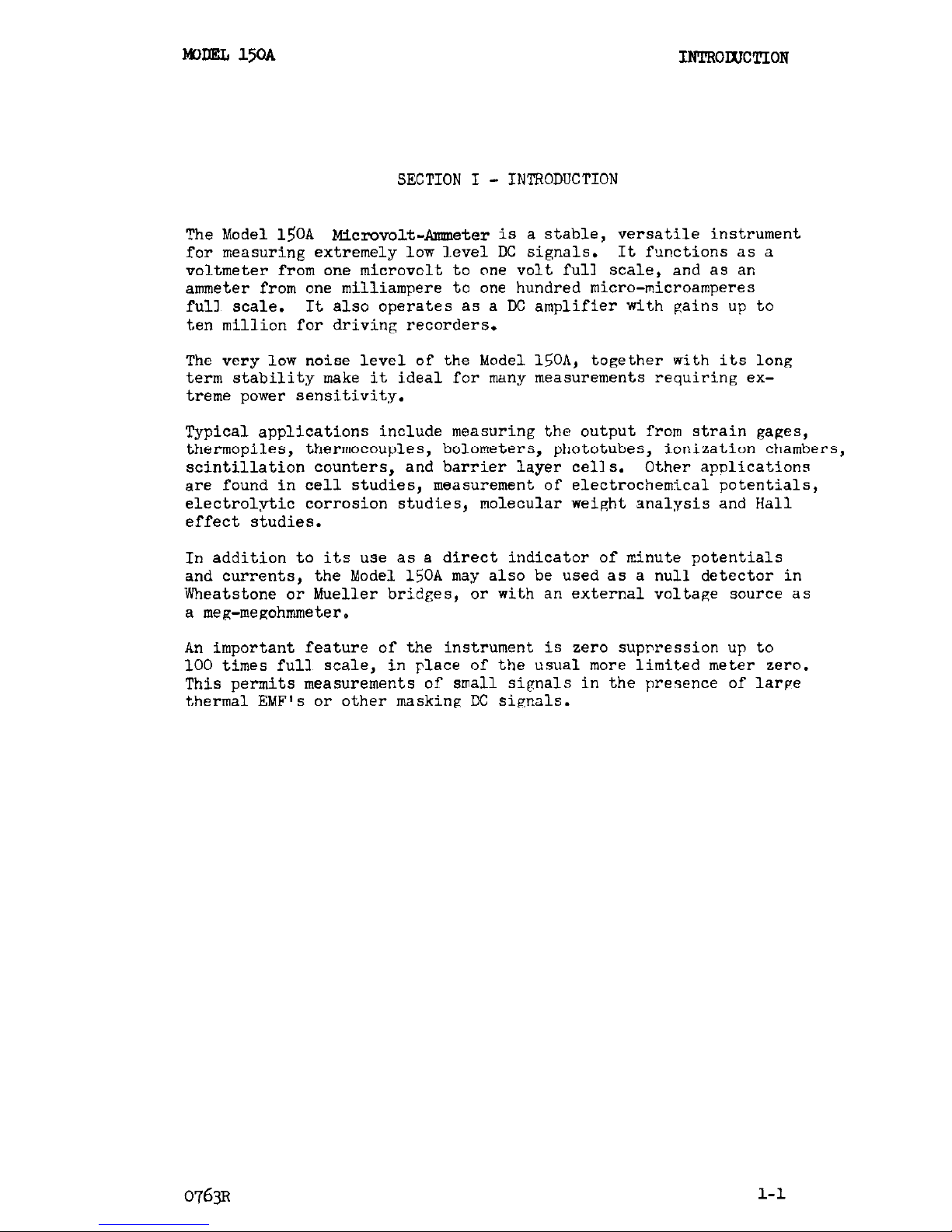
TABLE OF CONTENTS
section Page
Section
Page
I.
INTRODUCTION. . . 1-l D. Zero Suppression. . . . . .
4-2
II.
III.
A.
B.
C.
D.
E.
F.
IV.
A.
B.
C.
SPECIFICATIONS .
2-l
OPERATION . . 3-l
Operating Controls.
3-l
Preliminary Set-up. 3-l
General Precautions
3-2
Measuring Voltages. 3-3
Measuring Current . 3-3
Other Applications. 3-3
CIRCUIT DESCRIPTION
Input Circuit , . .
AC Amplifier. . .
DC Amplifier. . . .
4-l
4-l
4-l
4-l
E.
Other Controls. . . . . 4-2
F.
Power Supply. . . . . . .
4-2
V.
MAINTENANCE. . . . . .
5-l
Trouble-Shooting. . . . 5-l
Excessive Output Noise. . 5-l
Output Not Zero . 5-2
220-Volt Operation. . . 5-2
VI. REPLACEABLE PARTS . . . .
6-1
Models 150A,
150AR Replaceable
Parts List . . . .
6-2
Model 1501 Replaceable Parts
List............
6-7
Model 1502 Replaceable Parts
List............
6-7
Voltage Resistance Chart. . 6-9
Schematic Diagram 12188D.
6-11
9~ Change Notice
* Yellow Change Notice sheet is included only for instrument modifications
affecting the Instruction Manual.
0764R
i
Page 4
MODEL 150A
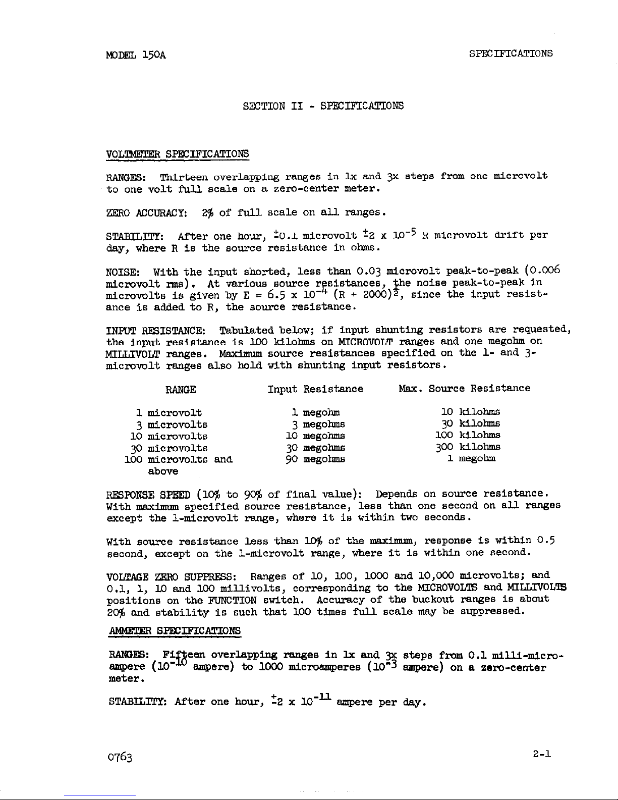
SECTION I
- INTRODUCTION
1NTR0lxlc!rI0n
The Model 150A Microvolt-Ammeter is a stable, versatile instrument
for measuring extremely low level DC signals. It functions as a
voltmeter from one microvolt to one volt full scale, and as an
ammeter from one milliampere to one hundred micro-microamperes
full scale.
It also operates as a DC amplifier with gains up to
ten million for driving recorders.
The very low noise level of the Model 150A, together with its long
term stability make it ideal for many measurements requiring extreme power sensitivity.
Typical applications include measuring the output from strain gages,
thermopiles, thermocouples, bolometers, phototubes, ionization chambers,
scintillation counters, and barrier layer cells. Other apnlications
are found in cell studies, measurement of electrochemical potentials,
electrolytic corrosion studies, molecular weight analysis and Hall
effect studies.
In addition to its use as a direct indicator of minute potentials
and currents, the Model 150A may also be used as a null detector in
Wheatstone or Mueller bridges,
or with an external voltage source as
a meg-megohmmeter.
An important feature of the instrument is zero supnression up to
100 times full scale,
in place of the usual more limited meter zero.
This permits measurements of small signals in the presence of large
thermal EMF's or other masking DC signals.
l-l
Page 5
MDLRL 15OA
SPECIFICATIONS
SECTION II -
SPECIFICATIONS
VOLllvIETw sF%xxlxcATIoRS
RANCE.:
Thirteen overlapping ranges in lx and p steps from one micrcvolt
to one volt full scale on a zero-center meter.
ZERO AccuRAcy: 2% of full scale on all ranges.
STABILITY:
After one hour,
+O.lmicrovolt +2 x 1O-5 R microvolt drift per
day, where R is the source resistance in ohms.
NOISE:
With the input shorted, less than 0.03 microvolt peak-to-peak (0.006
nlicmvo1t m3). At various
cmrce
r&sistances, she noise peak-to-peak in
microvolts is given by E = 6.5 x lo- (R + ZOoO)~, since the Input resistance is added to R, the source resistance.
INFUT RHISTANCE:
Tabulated below; if input shunting resistors are requested,
the Input resistance is loo kilohms on MICROVOLT ranges and one megohm on
MILLIVOIiT rages.
maximum murce resistancea specified on the l- and 3microvolt ranges also hold with shunting input resistors.
RAliOE
lmicrovolt
3 micrcvolts
10 microvolts
30 micrcvolts
loo microvolts and
above
Input Resistance
1 megohm
3 megohms
10 megohms
30 megohms
90 megohms
Max. Source Resistance
10 kilohms
30Mlom
100 kilohms
300 kilohms
1 megohm
RESPONSE SPEE!D (1% to VC$ of final value):
Depends on ~0urc.e resistance.
With maximum specified source resistance,
less than one second on all ranges
except the l-microvolt range,
where it is within two seconds.
With source resistance less than l@ of the maximum, response is within 0.5
second, except on the l-microvolt range, where It is within one second.
VOLTAOE ZERO SUPPRE!SS: Ranges of lo, 100, loo0 and 10,OoO micmvoltS; and
0.1, 1, 10 and loo millivolts, corresponding to the MICROVOLTS and MILLIVOLlB
positions on the FUNCTION switch.
Accuracy of the buckout ranges Is about
2% and stability is such that 100 times full scale may be suppressed.
RANLIES:
Fi
ampere (10'
in
een overlapping rangee in IX and p steps from 0.1
SIIIJA-~~C~-
smpere) to loo0 microamperes (10'3 ampere) on a zero-center
meter.
STABILTPY: After one hour', 22 x lO-ll ampere per day.
0763
2-l
Page 6
sPFCLF1cATI0NS
MODEL 15OA
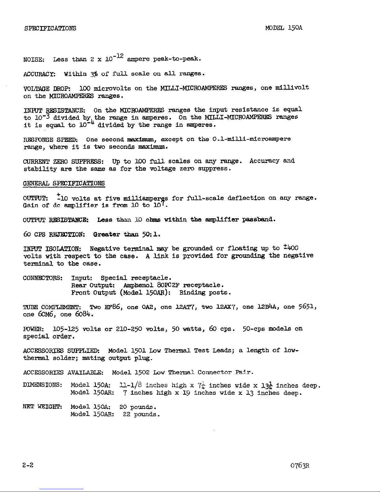
NOISE:
Less than 2 x 10-12
ampere peak-to-peak.
ACCURACY: Within 3% of full scale on all ranges.
VOLTAGE DROP:
100 microvolts on the MILLI-MICRO
AlmZRES ranges, one millivolt
on the MICROAMFERES ranges.
INFVT RESISTANCE: On the MICRCAMPERES
ranges the input resistance is equal
to 10-3 divided bx&the range in amperes. On the MILLI-MICROAMPERES ranges
it is equal. to 10
divided by the range in amperes.
RESPONSE SPEED:
One second maximum, except on the 0.1~milli-microampere
range, where it Is two seconds maximum.
CURRENT ZERO swpREss:
Up to 100 full scales on any range. Accuracy and
stability are the same as for the voltage zero suppress.
GENERAL SPECIFICATIONS
ouTHl* +
-I.0 volts at five milliemper s for full-scale deflection on any range.
Gain of dc amplifier is from 10 to lG 7 .
OUTPUT RmT.sTANcE:
Less than 10 dms within the emplifierpassbend.
60 CFS REJ-EZTION:
Greater than
50:
1.
-LNHJl! ISOLATION:
Neg8tiVe
terminal may be grounded or floating up to +&JO
volts with respect to the case.
A link is provided for grounding the negative
terminal to the case.
CONNECTORS: Input: Special receptacle.
Rear Output: Amphenol 8GPC2F
receptacle.
Front Output (Model15OAR): Binding posts.
'IUBE COMPLEMENT: TWO
~~86,
one 0~2, one l2~T'7, two 12~x7, one 12&A, one 5651,
one 6~~6, one
6084.
TOWER:
Lo5-125
v0lt.s OP
210-250
Mlts,
50
watts, 60 CPS.
50-CPS
models on
special order.
AccEssoRIEs SUPPLIED:
Model 1501 Low Thensal Test Leads; a length of low-
thermal solder; mating output plug.
ACCESSORIES AVAILABLE:
Model 1502 Low Thermal Connector Pair.
DIMENSIONS: Model 15OA:
U.-l/6 inches high x 7$ inches wide x ,13* inches deep.
Model 15OAR:
7 inches high x 19 inches wide x 13 inches deep.
NET WEIGRTz Model 150A:
20
pounds.
Model 15OAR:
22
pounds.
2-2
0763~
Page 7
I&XIEL 15OA
OFTRAl'ION
SECTION
III -
OPElRATION
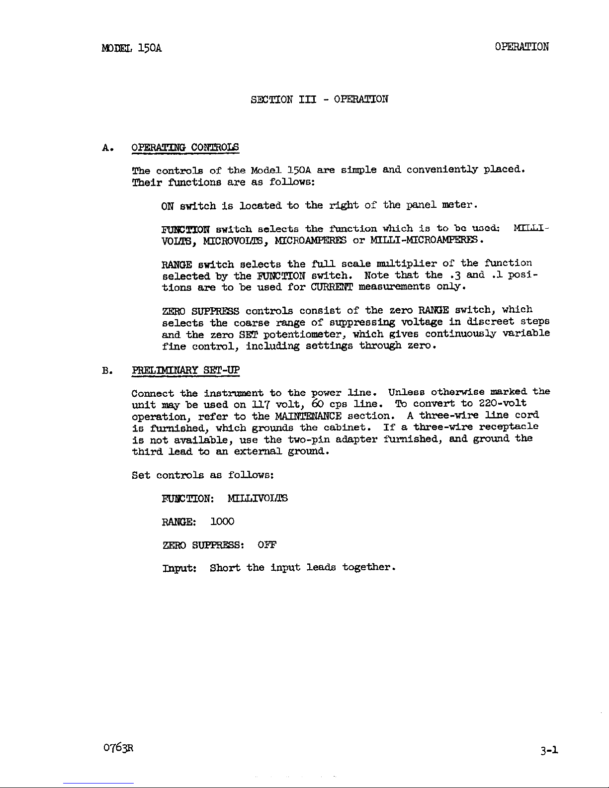
A. o- c0mR0J.s
The controls of the Modell5OA exe simple and conveniently placed.
Their functions are as follows:
ON switch is located to the right of the panel meter.
l?UICTION stitch selects the fkuction which is to be used: MILLI-
vom, MIcmvoLm, MICRO-
or MILLI-MICROAMPERES.
RANGE switch selects the full scale multiplier of the function
selected by the IBJNUTION switch.
Note that the .3 and .l posi-
tions are to be used for CURRENT measurements only.
ZEIiU SUPPRESS controls consist of the zero RA!K$E switch, which
selects the coarse range of suppressing voltage in discreet steps
and the zero SET potentiometer,
which
gives continuously variable
fine control, including settings through zero.
B.
PBELrnY SET-UP
Connect the instrument to the power line. Unless otherwise marked the
unit may be used on IL7 volt, 60 cps line. To convert to 220-volt
operation, refer to the MAINTENANCE section.
Athree-wire line cord
is furnished, which grouuds the cabiuet.
If a three-wire receptacle
is not available, use the two-pin adapter furuished, and ground the
third lead to e.n external ground.
Set controls as follows:
FlJfEIIION: MILLIVOLTS
RANGE: loo0
.zEm s-s: OFF
Inptl~
Short the input leads together.
0763~
3-l
Page 8
MDDEL 150A
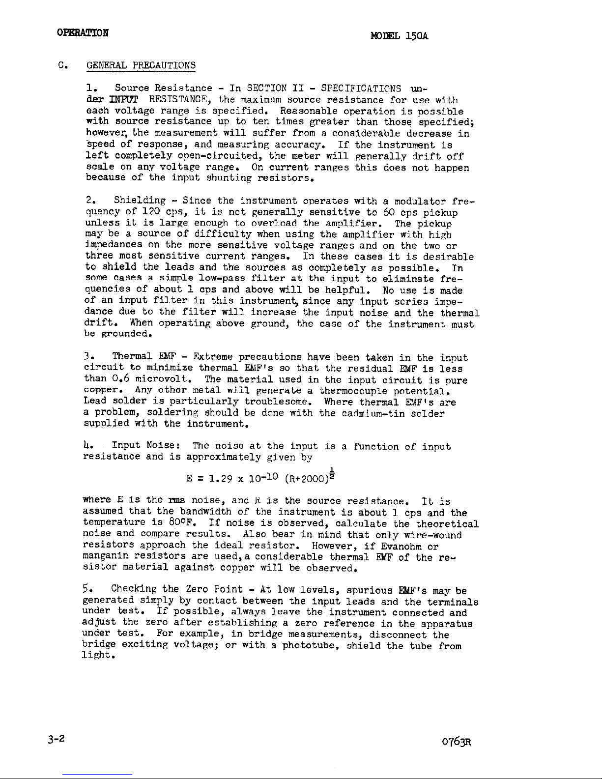
C.
GENERAL PRECAUTIONS
1.
Source Resistance - In SECTION II - SPECIFICATIONS under INRJT RESISTANCE, the maximum source resistance for use with
each voltage range is specified. Reasonable operation is possible
with source resistance up to ten times greater than those specified;
however, the measurement will suffer from a considerable decrease in
speed of response, and measuring accuracy. If the instrument is
left completely open-circuited, the meter will generally drift off
scale on any voltage range. On current ranges this does not happen
because of the input shunting resistors.
2.
Shielding - Since the instrument operates with a modulator fre-
quency of 120 cps, it is no% generally sensitive to 60 cps pickup
unless it is large enough to overload the amplifier.
The pickup
may be a source of difficulty when using the amplifier with high
impedances on the more sensitive voltage ranges and on the two or
three most sensitive current ranges. In these cases it is desirable
to shield the leads and the sources as completely as possible. In
some cases a simple low-pass filter at the input to eliminate frequencies of about 1 cps and above will be helpful. No use is made
of an input filter in this instrument, since any input series impedance due to the filter will increase the input noise and the thermal
drift.
When operating above ground, the case of the instrument must
be grounded.
3.
Thermal E&iF - Extreme precautions have been taken in the input
circuit to minimize thermal EMF's so that the residual EMF is less
than 0.6 microvolt.
'Ihe material used in the input circuit is pure
copper. Any other metal will generate a thermocouple potential.
Lead solder is particularly troublesome.
Where thermal EMF's are
a problem,
soldering should be done with the cadmium-tin solder
supplied with the instrument.
Ir.
Input Noise:
The noise at the input is a function of input
resistance and is approximately given by
E q 1.29 x lo-lo (R+2000)$
where E is the rms noise,
and R is the source resistance.
It is
assumed that the bandwidth of the instrument is about 1 cps and the
temperature is SOoF.
If noise is observed,
calculate the theoretica
noise and compare results.
Also bear in mind that only wire-wound
resistors approach the ideal resistor.
However, if Evanohm or
manganin resistors are used,a considerable thermal EMF of the re-
sistor material against copper will be observed.
5.
Checking the Zero Point - At low levels, spurious E&W's may be
generated simply by contact between the input leads and the terminals
under test.
If possible,
always leave the instrument connected and
adjust the zero after establishing a zero reference in the apparatus
under test.
For example,
in bridge measurements, disconnect the
bridge exciting voltage; or with a phototube, shield the tube from
light.
3-2
0763~
Page 9

MODEL 150A OPERATION
6. Overloads - The current applied to the input circuit should be less
than one milliampere dc steady
state,
10 milliamperes dc short-term.
When the FUNCTION switch is on the MILLIVOLTS position, the off-scale
impedance can be as low as 10 kilohms. On the MICROVOLTS position, it
may approach 10 ohms.
D. MEASURING VOLTAGE
1.
Direct Voltage Measurements - Place the FUNCTION switch at
MILLIVOLTS or MICROVOLTS as necessary for the measurement to be taken
Then turn the RANGE switch to more sensitive ranges until the meter
gives a usable deflection.
2.
Measuring Voltage Variations - Set the FUNCTION switch and RANGE
switch to obtain the best deflection of the meter. Use the ZERO SUPPRESS controls as described in IV-D to increase the sensitivity of
the meter. Then small changes in a relatively large steady signal may
be displayed with a large scale deflection.
3. Measuring Differential Voltages - When measurements are to be made
in a circuit where the LOW connection is above ground potential, remove the DISCONNECT LINK from one of its posts. This disconnects the
instrument circuit ground from chassis ground. DO NOT attempt to make
such measurements where the low side of the circuit being measured is
more than 400 volts above external ground potential.
If a recorder is being used with the instrument in this arrangement,
the recorder ground must not be connected to the output ground of the
instrument, since the low side of the output would no longer be grounded.
E.
MEASURING
UNRENT
Direct Current Reading - Turn the FUNCTION switch to MICROAMPERES or
MILLI-MICROAMPERES, and the RANGE to 1000.
Connect the instrument to
the current source and set the RANGE to the range which gives the
best deflection of the meter.
Measuring Current Variations - Proceed as above for direct current
readings,
and then use the ZERO SUPPRESS and SET as described under
IV-D.
F.
OTHER APPLICATIONS
1.
Null Indicator - The Model 510A makes an extremely sensitive null
indicator which may be used in a Wheatstone or Mueller Bridge.
In a Wheatstone Bridge,
the Model 150A is connected between the two
resistor arms.
With the FUNCTION on MILLIVOLTS, and the RANGE on 1000,
the bridge can be adjusted to give a zero reading on the meter. The
instrument can then be set on more sensitive ranges for finer adjustments
of the bridge,*
*If the bridge is arranged so that one terminal of the detector is
grounded, the Model 150A may be used as described in E.
If the
detector must be used floating, remove the DISCONNECT LINK at the
rear and observe the same precautions as in D.3.for measuring
differential voltages.
0764R 3-3
Page 10

OPERATION
MODEL 150A
2.
Megohmmeter - The Model 510A may be used to measure resistances,
utilizing an external voltage source and measuring the current which
flows in the unknown.
3-4
0764R
Page 11
MODEL I.5OA
CIRCUPP DY&CRIppIoIi
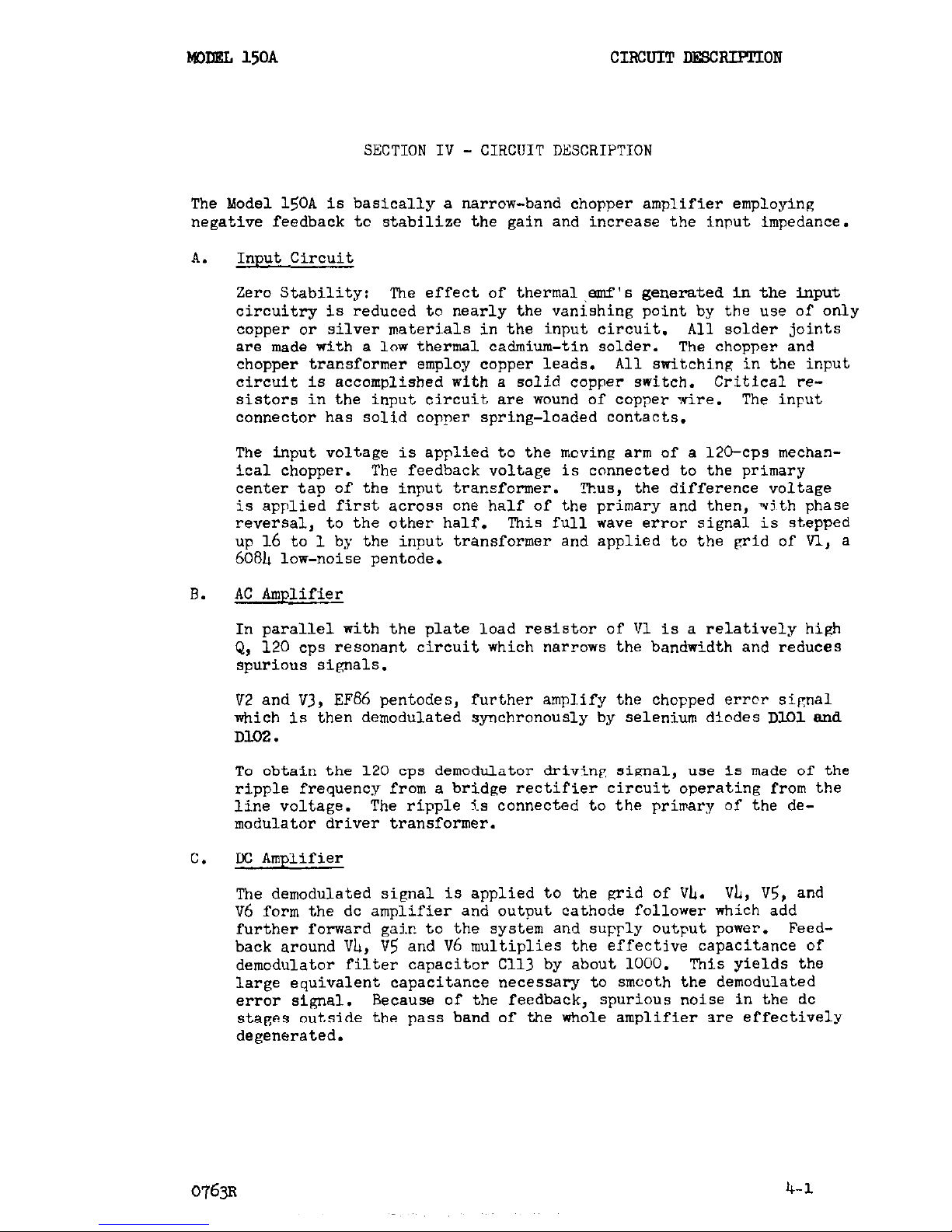
SECTION IV - CIRCUIT DESCRIPTION
The Model 150A is basically a narrow-band chopper amplifier employing
negative feedback to stabilize the gain and increase the input impedance.
A. Input Circuit
Zero Stability: The effect of thermal W's generated in the input
circuitry is reduced to nearly the vanishing point by the use of only
copper or silver materials in the input circuit. All solder joints
are made with a low thermal cadmium-tin solder. The chopper and
chopper transformer employ copper leads.
All switching in the input
circuit is accomplished with a solid copper switch. Critical resistors in the input circuit are wound of copper wire. The input
connector has solid copper spring-loaded contacts.
The input voltage is applied to the moving arm of a 120-cps mechanical chopper.
The feedback voltage is connected to the primary
center tap of the input transformer. '%us, the difference voltage
is applied first across one half of the primary and then, +th phase
reversal, to the other half.
This full wave error signal is stepped
up 16 to 1 by the input transformer and applied to the grid of VI., a
608h low-noise pentode.
B.
AC Amplifier
In parallel with the plate load resistor of Vl is a relatively high
Q, 120 cps resonant circuit which narrows the bantiidth and reduces
spurious signals.
V2 and V3, EF86 pentodes, further amplify the chopped error sipnal
which is then demodulated synchronously by selenium diodes DlOlend
Dl.02.
To obtain the 120 cps demodulator driving sianal, use is made of the
ripple frequency from a bridge rectifier circuit
operating
from the
line voltage.
The ripple Js connected to the primary of the de-
modulator driver transformer.
C.
tC Amplifier
The demodulated signal is applied to the grid of VL. Vii, V5, and
~6 form the dc amplifier and output cathode follower which add
further forward gair. to the system and
supply output
power. Feedback around VL, V5 and V6 multiplies the effective capacitance of
demodulator filter capacitor Cl13 by about 1000. This yields the
large equivalent capacitance necessary to smcoth the demodulated
error signal.
Because of the feedback, spurious noise in the dc
stages outside the pass band of the whole amplifier are effectively
degenerated.
0763~
4-l
Page 12

CIRCUll’ WBXIFTION
MIDELL 150A
D.
Zero Suppression
A low-current *lo volt supply is derived from the main dc supply
using lo-volt sener diodes.
Potentiometer Rl7h may be set at any
voltage from -10 to +lO volts,
this voltage being applied through ap-
propriate dropping resistors to the feedback point to achieve sero
suppression. The potentiometer is the front panel control marked
SET, while switch
S3,
which detemAnes the portion fed back, is
Labeled RANGE.
E.
Other Controls
Three controls are set at the factory and should require only infre-
quent attention by the user.
R118 is an internal control marked DC AMP BAL. It is used to zero the
IX amplifier, i.e.,
to set the output voltage to sero when the de-
modulator output is zero.
This is not very critical since any unbal-
ance will simply be fed back to the inout to produce a small error signal
to correct itself.
RlS7is markedME!WR:CAt.
This is the variable
portion of the meter multiplier resistance to allow for meter-to-meter
sensitivity differneces.
FCL77,
marked CURRENT BALAE!CE, may be set at some voltage which will
cause a current to flow through Rl75 to the chopper am. This current
is used to compensate for a
small
generated "chopper current" which
would otherwise flow in the input circuit.
This "chopper current"
differs from chopper to chopper,but is fairly
stable
for long periods
of time. Its effect on any current range could be removed with the
ZERO SUPPRESS controls, but the Current Balance method used here gives
an effective aero input current for all ranges.
F.
Power Supply
A standard half-wave rectifier followed by an R-C filter is used to
supply unregulated B+ and B- to the output cathode follower.
The unregulated B- is regulated to
-150 volts in V7, OA2, and is used
for the negative returns for the dc amplifier.
Unregulated B+ is fed to the plate of V8, 12BU, the series tube in a
225-volt electronic regulator. The output voltage from this regulator
is divided by R510 and P.511 and compared to reference tube V9, a
5651.
The difference signal is amplified
by
cascade amplifier VlO, a 12AX7,
and applied to the grid-cathode circuit of the series tube.
This
regulated 225 volts supplies Bc directly to the dc amplifier, through
a decoupling filter (R176, CllO) to the second and third ac amplifier
stages, and through another decoupling filter (R103, ClOh) to the
first ac amplifier stage.
Regulated B+ and B- also supply currents to the 10 volt sener diodes
which are used for xero suppression. This gives two-stage regula-
tion for these very critical voltages.
The first two ac amplifier filaments and the first dc amplifier fila-
ments are driven by a bridge-rectified 6-volt d.c. supply.
The R-C
filter, R512, C507, and ~5~8, insure lowripple.
4-2
0763
Page 13

Mom
15oA
SECTION V -
MAINTENANCE
MAIAPENAIOCE
Except for occasional tube or chopper replacement, very little maintenance
is required by the Models 150A and 15OAR.
Components are operated well
below rating and solid-state devices are employed where possible to achieve
long, trouble-free service.
Certain portions of the input circuit are wired using copper wire and special
cadmium-tin solder.
These special joints are painted red. If, for any
reason, these joints must be unsoldered or re-soldered, USE ONLY CADMIUM-
TIN SOLDER AND A COPPER-TIPPED SOLD!iRING IRON !'bMICH HAS NEVER BEEN USED WITH
ORDINARY LEAD-TIN SOLDER.
A small spool of cadmium-tin solder is supplied
with each instrument.
What may seem to be circuit failure in the Micro Volt-Ammeter is quite often
found to be an unusual condition in the entire test set-up. Therefore, before trouble-shooting the instrument,
check to see whether it operates cor-
rectly with:
1.
All other circuitry disconnected.
2.
Input shorted (with copper leads).
3.
Power line voltage and frequency correct.
If the difficulty persists,
the following systematic procedure may be em-
ployed to determine the fault.
TROUBLE-SHOOTING
Reference is made to the Schematic Diagram, lZl@8D, and the Voltage-
Resistance Diagram enclosed at the rear of the manual.
To begin trouble-shooting, short the input terminals, strap chassis ground to IO
withthe link pmvided(Model15OAB only), and switchRANGE to OFF.& zero off-
set of a few tenths of a microvolt is noml. On current functions with the
input terminals open but shielded,
it should be possible to set aero current
with the CURRENT BALANCE control.
EXCESSIVE OUTPUT NOISE (INPUT TmINALS SHORTED)
Short the input grid of the dc amplifier, pin 7 of Vk, to ground. If this
stops the noise,
it is being generated in the ac amplifier. Unfortunately,
because of the very low signal levels involved, noise in the ac amplifier
is difficult to trace by other than the substitution method. Most logical
noise sources are Vl or the chopper.
To replace the chopper, unplug the
cap at the top, and unscrew the three thumb-screw nuts which
clamp
the chop-
per leads.
Unscrew the four chopper mounting screws and lift out the chopper.
When inserting the new chopper,
make sure that the chopper leads are pressed
against the copper terminals and that the insulating washers are between
the leads and the thumb-screw nuts. ,Observe wiring so as to rewire exactly
the same as the original.
5-l
Page 14

-CE
M)DEL 15OA
If the noise persists after shorti.ng the dc amplifier input, the noise is
being generated in the dc amplifier or power supply. A stage-by-stage
search should reveal the source.
OUTPUT NOT ZERO (INPUT TERMINALS SHORTED)
Be sure that RAIWE is set to OFF.
Short the clc amplifier input grid,
pin 7 of Vh, to ground.
Use the DC AMP BAL control to set the output to
zero.
If this cannot be done, the dc amplifier or power supply are at
fault.
If it can be set to zero, the trouble may be in the ac amplifier
or demodulator circuit.
- B+ should be about +225 on pin 1 of ~8
Zoui~ pins 2, h or 7 of v7. If v7 is not fir&
and B-
correct the fault in the unregulated B-. If +225 is not pre;ent,
check for unregulated B4 (about 3LO vclts) at the plate pin 9 of
va. If
the
unregulated Ik is all right, check the tube pin voltages
of ~8, V9, and VlO to locate the faulty tube or part.
b.
AC Amplifier
- Remove
the
output
tube (~6) and
clip
pir 1 of
the output connector to ground. Place the FlJBCTION switch on
MlLLIVOLTS, and turn the SJEC and RANGE controls full
clockwise. This puts a large dc error signal across the chopper
and input transformer.
Use an oscilloscope to check for the
presence of 120 cps at the primary of the input trsnsformers (the
two outside terminals on the chopper terminal block). Absence of
signal means chopper failure (or much less likely, shorted input
transformer). Listen for audible chopper action and check chopper
drive, if necessary.
If the 120 cps signal is present,
check stage-by-stage throughout
the ac amplifier,
reducing the input signal as desired by backing
off the RANGE and/or SET controls, until the failure is
discovered.
d.
Demodulator Circuit - Check for presence of about 80 volts at the secondary of the demodulator transformer (at the ends of R113
and Rllh).
The tests outlined above will not suffice to pin-point every fault
which may exist. They should, however, lead to the correction of
common failures.
In the event that troubles cannot be corrected
by these
means,
or the user finds it more expedient, the unit may
be returned to the factory for repair and recalibration at a
nominal cost.
220-VOLT OPERATION
For 220~volt operation the
power
transformer primary connections must be
changed. The jumpers connecting black and black-white together and blue
and blue-white should be removed.
The blue and black-white leads should
be tied together. Replaos the 1.5 tuapere fuse (Keith&y part m-8) with
a 0.75 ampere fuse (Kaithley part W-14).
5-B
Page 15
MODELS 150A, 15OAR MICROVOLT-AMMETERS REPLACEABLE PARTS
SECTION 6.
REPLACEABLE PARTS
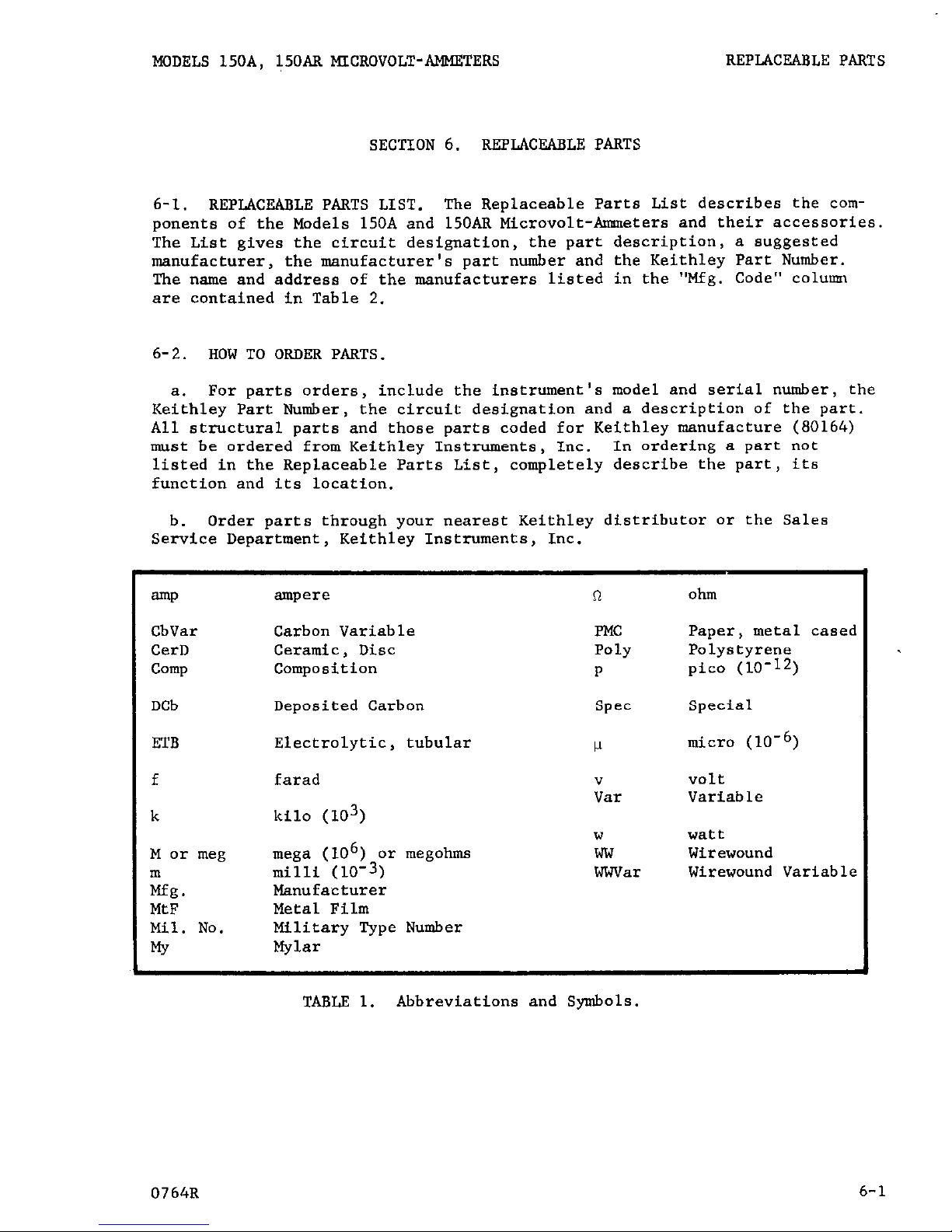
6-1. REPLACEABLE PARTS LIST.
The Replaceable Parts List describes the components of the Models 150A and 15OAR Microvolt-Ammeters and their accessories.
The List gives the circuit designation,
the part description, a suggested
manufacturer,
the manufacturer's part number and the Keithley Part Number.
The name and address of the manufacturers listed in the "Mfg. Code" column
are contained in Table 2.
6-2.
HOW TO ORDER PARTS.
a. For parts orders,
include the instrument's model and serial number, the
Keithley Part Number, the circuit designation and a description of the part.
All structural parts and those parts coded for Keithley manufacture (80164)
must be ordered from Keithley Instruments, Inc.
In ordering a part not
listed in the Replaceable Parts List, completely describe the part, its
function and its location.
b.
Order parts through your nearest Keithley distributor or the Sales
Service Department, Keithley Instruments, Inc.
aP
CbVar
CerD
camp
DCb
ETB
ampere
Carbon Variable
Ceramic, Disc
composition
Deposited Carbon
Electrolytic, tubular
n
Ohm
FMC
Paper, metal cased
Poly Polystyrene
P
pica (10-12)
Spec Special
w
micro (10-6)
f farad
v
volt
Var
Variable
k kilo (103)
w
watt
M or meg mega (106) or megohms
ww Wirewound
m
milli (10-3)
WWVar
Wirewound Variable
Mfg.
Manufacturer
MtF
Metal Film
Mil. No.
Military Type Number
rs
Mylar
TABLE 1.
Abbreviations and Symbols.
0764R
6-l
Page 16

REPLACEABLE PARTS MODELS 150A, 15OAR MICROVOLT-AMMETERS
MODELS 150A, 15OAR REPLACEABLE PARTS LIST
(Refer to Schematic Diagram 12188D for circuit designations.)
CAPACITORS
Circuit
Desig. Value
Mfg.
Mfg. Keithley
Rating Type Code
Part No. Part No.
Cl01 ".047-.33 pf
200 v
Cl02
Cl03
Cl04
Cl05
4.7 IJf
.1 pf
20 IJ.f
.l pf
.0082 pf
.0122 pf
4.7 wf
.Ol pf
.l pf
20 pf
10 v
200 v
450 v
400 v
Cl06 (60 cps)
Cl06 (50 cps)
Cl07
Cl08
Cl09
Cl10
100 v
100 "
10 "
600 v
200 "
450 v
Cl11
Cl12
Cl13
Cl14
Cl15
Cl16
Cl17 (50 cps)
c501
C502
c503
c504
c505
C506
c507
C508
c509
4.7 pf
.l pf
333 If
:001 pf
.0047 Kf
.OOl bf
.0047 I*f
20 pf
20 pf
20 vf
.Ol wf
20 pf
"0.5 I*f
1000 pf
1000 pf
.1 I.lf
Circuit
Desig.
Type
10 "
400 v
200 "
600 v
600 v
600 v
600 v
600 v
450 v
600 v
600 v
450 "
600 v
12 v
12 v
400 v
MY
00656
ETB 05397
PMC 00656
ETB 56289
MY 00656
Poly 84171
Poly 84171
ETB 05397
CerD 72982
PMC 00656
ETB 56289
ETB 05397
MY 00656
MY 00656
CerD 72982
CerD 72982
CerD 72982
CerD 72982
ETB 00656
ETB 56289
ETB 00656
CerD 72982
ETB 56289
MY 14655
ETB 83125
ETB 83125
MY 14655
DIODES
Mfg.
V84C-V161 C29-$<
K4R7-JlOS C71-4.7M
P82-Z C18-.lM
TVA1709
C8-20L
V84C-V161' C30-.lM
PE C45-.0082M
PE
C45-.0122M
K4R7-JlOS C71-4.7M
811Z5VlO3P C22-.OlM
P82-Z Cl%.lM
TVA-1709 C8-20L
K4R7-JlOS C71-4.7M
V84C-V161 C30-.lM
V84C-V161 C29-.333M
80125V102P CZZ-.OOlM
811Z5V472P C22-.0047M
80125VlO2P C22-.OOlM
811Z5V472P C22-.0047M
PRS-1890 C35-20M
TVA1709 C8-20L
PRS-1890
C35-20M
811Z5VlO3P C22-.OlM
TVA1709
C8-20L
PM-65P C92-0.5M
TDlOOO-15 Cll-1000M
TDlOOO-15 Cll-1000M
PM-65P
C30-.lM
Keithley
Number Code
Part No.
DlOl
D102
D103
D104
D105
Selenium
Selenium
Zener
Zener
Selenium
5Ul
5Ul
lN71p;
lN71,W
PT065
81483 RF-15
81483
RF-15
12954
DZ-2.1
12954 DZ-2,X
81483 RF-18
Nominal value, factory selected.
6-2
0764R
Page 17

MODELS 150A, 15OAR MICROVOLT-AMMETERS
REPLACEABLE PARTS
DIODES (Cont'd)
Circuit
Desig.
D106
D107
D108
D109
DllO
Dill
Mfg.
Keithley
Type
Number
Code
Part No.
Selenium PT065 81483 RF-18
Sf?leIliUm PT065 81483 RF-18
Selenium PT065 81483 RF-18
Selenium PT065
81483 RF-18
Selenium
PT065 81483 RF-18
Selenium Bridge ClB
81483
RF-7
MTSCELLANEOUS PARTS
Circuit
Desig. Description
Mfg.
Keithley
Code Part No.
Fl (117 v) Fuse, 1.5 amp, 3 AG
Fl (234 v) Fuse, 0.75 amp, 3 AG
---
Fuse Holder (Mfg:No. 34201)
Gl (60 cps)
Gl (50 cps)
Jl
--_
Chopper
Chopper
Receptacle Assembly, Input
Plug, Special, Mate of Jl
s2
---
Receptacle, Microphone, OUTPUT
mfg. NO. 80P~2~)
Plug, Microphone, Mate of 52
(Mfg. NO. 80~~2.0
--(r)
--(r)
--CT)
Binding Post OUTPUT (Mfg. No.
DF21RC)
Binding Post, LO (Mfg. No.
DFZlBC)
Binding Post, G (Mfg. No.
DFZlBC)
--(r)
Ll
M
---
Pl
---
Sl
Shorting Link (Mfg. No. 938-L)
Choke, 200 hy
Meter
Meter Lamp (Mfg. No. 323)
Power Cord, 6 feet (Mfg. No.
4638-13)
Cable Clamp
Rotary Switch less components,
FUh'CTION
75915 FU-8
75915
FU-14
75914
FH-3
80164
cv-2
80164
cv-3
80164 12450B
80164
13011B
02660 CS-32
02660 cs-33
58474
58474
58474
24655
80164
80164
08804
BP-11R
BP-11B
BP-11B
BP-6
m-1
ME-14
PL-1
82879
co-2
80164
cc-7
80164 SW-56A
(r) Used only on Model 15OAR.
0764R
6-3
Page 18
REPLACEABLE PARTS
MODELS 150A, 150AR MICROVOLT-AMMETERS
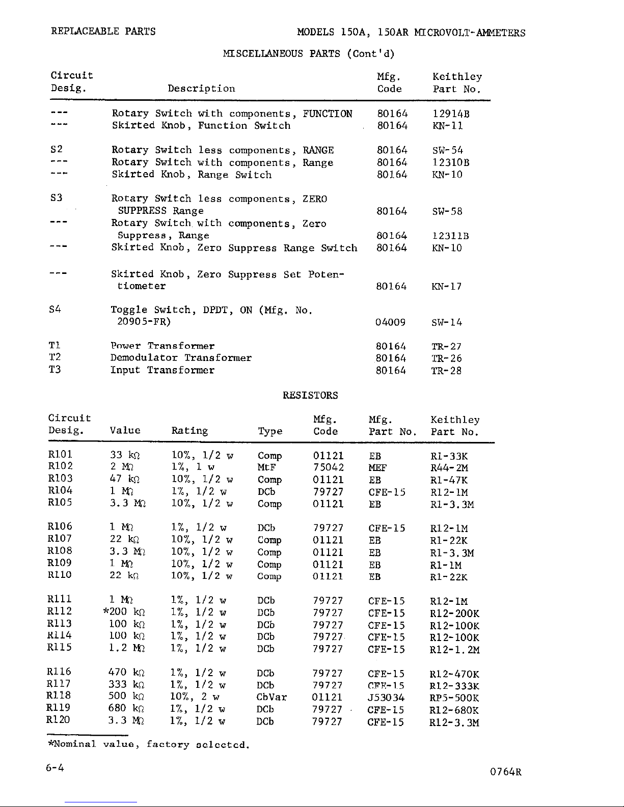
MISCELLANEOUS PARTS (Cont'd)
Circuit
Desig. Description
Mfg.
Keithley
Code Part No.
---
---
s2
---
53
---
---
---
s4
Tl
T2
T3
Rotary Switch with components, FUNCTION
Skirted Knob, Function Switch
Rotary Switch
less components,
RANGE
Rotary Switch with components, Range
Skirted Knob, Range Switch
Rotary Switch less components, ZERO
SUPPRESS Range
Rotary Switch with components, Zero
Suppress, Range
Skirted Knob, Zero Suppress Range Switch
Skirted Knob, Zero Suppress Set Poten-
tiometer
Toggle Switch, DPDT, ON (Mfg. No.
20905-FR)
Power Transformer
Demodulator Transformer
Input Transformer
RESISTORS
Circuit
Mfg.
Desig. Value Rating
5Pe
Code
80164 12914B
80164
m-11
80164
SW-54
80164
12310B
80164
l-w-10
80164
80164
80164
SW-58
12311B
la- 10
80164
KN-17
04009
SW-14
80164 TR-27
80164 'IX-26
80164
TR-28
Mfg.
Keithley
Part No.
Part No.
RlOl 33 k-l
R102
2m
R103 47 kn
R104
l?%l
R105 3.3 a-l
R106
1m
R107
22
krl
R108 3.3 im
R109
1m
RllO 22 kn
Rlll
ll%
R112
x200 k!J.
R113 100 Ilc2
R114 100 kn
R115 1.2 m
R116 470 kn
R117 333 kn
R118 500 kfl
R119 680 kn
R120 3.3 8-l
lO%, l/2 w
l%, 1 w
lO%, l/2 w
l%, l/2 w
lO%, l/2 w
l%, l/2 w
lO%, l/2 w
lO%, l/2 w
lO%, l/2 w
lO%, l/2 w
l%, l/2 w
l%, l/2 w
l%, l/2 w
l%, l/2 w
l%, l/2 w
l%, l/2 w
l%, l/2 w
lO%, 2 w
l%, 112 w
l%, l/2 w
Comp 01121
EB
Rl-33K
MtF
75042
MEF
R44-2M
camp 01121
EB Rl-47K
DCb
79727 CFE-15 RlZ-1M
camp
01121
EB
Rl-3.3M
DCb
Comp
Comp
Comp
camp
CFE-15 RlZ-1M
EB Rl-22K
EB
Rl-3.3M
EB Rl-1M
EB Rl-22K
DCb
DCb
DCb
DCb
DCb
79727
01121
01121
01121
01121
79727
79727
79727
79727
79727
79727
79727
01121
79727
79727
CFE-15 RLZ-1M
CFE-15 RLZ-200K
CFE-15 RLZ-100K
CFE-15 RlZ-100K
CFE-15
R12-1.2M
DCb
DCb
CbVar
DCb
DCb
CFE-15 Rl2-470K
CFE-15 RlZ-333K
553034 RP5-500K
CFE-15 RLZ-680K
CFE-15 RlZ-3.3M
timnina value, factory selected.
6-4
0764R
Page 19

REPLACEABLE PARTS MODELS 150A, 15OAR MICROVOLT-AMMETERS
RESISTORS (Cont'd)
Circuit
Mfg. Mfg.
Keithley
Desig. Value Rating
TYPO
Code Part No. Part No.
R121
R122
R123
R124
R125
R126
R127
R128
R129
R130
R131
R132
R133
R134
R135
R136
R137
R138
R139
R140
R141
R142
R143
R144
R145
R146
R147
R148
R149
R150
R151
Rl52
R153
R154
R155
R156
R157
R158
Rl59
R160
2.2 T-m
62
kn
100 kfi
1m
1Kl
30 kc?
10 kn
95.3 kn
Not Used
Not Used
Not Used
Not Used
'1220 kn
~~10 n
Ml0 kn
1.11 kn
100 kn
10 h-l
Not Used
10 kn
3.33 kc2
lk0
333 cl
100 n
33.3 n
10 n
"3.3311
x1.0 n
1Wl
333 kQ
100 kc)
33.3 ka
500 R
500 n
10 m
3.3 wl
1Wl
333 kn
99 kcl
32.3 kn
l%, l/2 w
l%, 1 "
l%, l/2 "
l%, l/2 w
l%, l/2 "
5%, 10 w
lO%, 2 w
l%, 1 "
lO%, l/2 w
1%
1%
l%, l/2 "
l%, 112 "
5%,
l%, l/2 w
l%, l/2 "
l%, l/2 "
l%, l/2 "
l%, l/2 "
l%, l/2 w
l%, l/2 w
l%, l/2 "
l%, l/2 "
l%, l/2 w
l%, l/2 "
l%, l/2 w
l%, l/2 "
l%, l/2 w
l%, l/2 "
l%, 1 w
lO%, l/2 w
l%, l/2 "
l%, l/2 "
l%, l/2 w
l%, l/2 "
*Nominal value, factory selected.
**Resistors R134 and R135 are matched to l/2%.
Order only as a pair.
0764R
DCb
DCb
DCb
DCb
79727 CFE-15 R12-2.2M
91637
DCF-1 R13-62K
79727 CFE-15 RlZ-100K
79727 CFE-15 RlZ-1M
79727 CFE-15 RlZ-1M
ww
War
MtF
63743
10F R5-30K
71450 WPIOK RP9-1OK
75042
CEC R94-95.3K
camp
01121
wspec
80164
wwspec
80164
EB Rl-220K
Rl8-18-10
R18-18-10K
DCbSpec
80164
R38-l.llK
DCbSpec 80164 R38-100K
wwspec
80164
R18-19-10K
DCb
79727
CFE-15 RlZ-10K
DCb
DCb
ww
ww
DCb
79727 CFE-15 RlZ-3.33K
79727 CFE-15 RlZ-1K
01686 7020 R48-333
01686 7020 R48-100
79727 CFE-15 RlZ-33.3
DCb
DCb
DCb
DCb
DCb
79727 CFE-15 R12-10
79727
CFE-15 Rl2-3.33
79727 CFE-15 R12-1.0
79727 CFE-15
RlZ-1M
79727 CFE-15 RlZ-333K
DCb
DCb
DCb
DCb
DCb
79727
CFE-15 RlZ-100K
79727
CFE-15 RlZ-33.3K
79727 CFE-15
RlZ-500
79727
CFE-15 RlZ-500
91637 DCF-1
R13-10M
camp
DCb
DCb
DCb
DCb
01121 EB Rl-3.3M
79727 CFE-15
RlZ-1M
79727
CFE-15 RlZ-333K
79727 CFE-15 RlZ-99K
79727 CFE-15
Rl2-32.3K
6-5
Page 20

REPLACEABLE PARTS
MODELS 150A, 150AR MICROVOLT-AMMETERS
RESISTORS (Cont'd)
Circuit
Mfg.
Mfg.
Keithley
Desig. Value
Rating
TYPO
Code Part No. Part No.
R161
R162
R163
R164
R165
R166
R167
RL68
R169
R170
R171
R172
R173
R174
R175
R176
R177
R178
R179
R180
R181
R182
R183
R184
R501
R502
R503
R504
R505
R.506
R507
R508
R509
R.510
R511
R512
9kQ
100 krl
390 kn
100 kn
47 kfl
15 krl
4.7 ksl
5.6 ksl
2.2 kn
llcn
1m
100 kcl
9 kn
10 kn
100 I-Q
10 k
10 kfl
75 ko
75 ksl
30 kn
**100 kn
Ml I$
*1 M
*82 n
100 n
100 R
5 kn
5kil
22 kQ
10 m
220 ko
33 kn
33 kG
1m
600 kn
6n
l%, II2 w
lO%, l/2 w
lO%, 112 w
lO%, l/2 w
lO%, 112 w
lO%, l/2 w
lO%, l/2 w
LO%, I.12 w
lO%, l/2 w
l%, 112 w
l%, l/2 w
l%, 112 w
l%, l/2 w
3%, 5 w
l%, 2 w
lO%, l/2 w
lO%, 2 w
l%, l/2 w
l%, l/2 w
5%, 10 w
l%, 1/4 w
l%, II2 w
lO%, l/2 w
l%, I./2 w
lO%, 2 w
lO%, 2 w
5%, 10 w
5%, 10 w
lO%, 2 w
lO%, 1/z w
l%, l/2 w
lO%, l/2 w
lO%, l/2 w
l%, l/2 w
l%, II2 w
lO%, 5 w
DCb
Comp
camp
camp
camp
79727
CFE-15
RlZ-9K
01121
EB
Rl-ZOOK
01121
EB
Rl-390K
01121
EB
Rl-100K
01121
EB
N-4X
camp
Comp
camp
camp
DCb
01121
EB
Rl-15K
01121
EB
Rl-4.7K
01121
EB
Rl-5.6K
01121
EB
Rl-2.2K
79727 CFE-15
RlZ-1K
DCb 79727
DCb 79727
DCb
79727
WWVar 73138
RlZ-1M
R12-100K
RlZ-9K
RP4-1OK
DCb 91637
CFE-15
CFE-15
CFE-15
A-RlOK-
125
DC- 2
R14-1OOM
camp
01121
EB
Rl-1OK
WWVar 71450
WPLOK RP9-1OK
DCb
79727
CFE-15 R12-75K
DCb
79727
CFE-15
R12-75K
ww 63743
10F
R5-30K
ww 80164
DCb 79727
Comp
01121
DCb
79727
CFE-15
EB
CFE-15
RlB-21-100K
RI?.-1M
Rl- 1M
RlZ-82
Comp
camp
ww
ww
camp
01121
HB
R3- 100
01121
HB
R3- 100
44655
BLUME
RS-5K
44655
BLUME
R5-5K
01121
HB
R3- 22K
Comp
DCb
Comp
camp
DCb
01121
EB
Rl- 10M
79727
CFE-15 R12-220K
01121
EB RI-33K
01121
EB RI-33K
79727
CFE-15 RlZ-1M
DCb
ww
79727 CFE-15 RlZ-600K
44655
4654 R4-6
+c Nominal value, factory selected.
ek Not
usually
in instrument
but supplied upon request
6-6
0764R
Page 21

-MODELS 150A, &SOAR MICROVOLT-AMMETER
REPLACEABLE PARTS
VACUUM TUBES
Circuit
Desig.
NUmber
Mfg.
Code
Keithley
Part No.
Vl
V2
v3
V4
v5
V6
V7
V8
v9
VlO
6084 73445 EV-6084/E80F
BF86 73445 EV-EF86/6267
EF86 73445 Ev-EF86/6267
12Ax7 73445 EV-12Ax7
12AT7 73445 EV-12AT7
6~~6 00011 m- 6~~6
*WA2 80164 BV-OA2
12B4A 85599 EV-12B4A
**5651 80164 m-5651
12AX7 73445 EV-12AX7
MODEL 1501 REPLACEABLE PARTS LIST
Description
Mfg.
Keithley
Code Part No.
Plug Assembly 80164 13011B
Cable, 48 inches, Vinyl, shielded 86696 SC-5
Alligator Clamps, (2), (Mfg. No. 6OC5)
76545 AC-8
MODEL 1502 REPLACEABLE PARTS LIST
Description
Mfg.
Code
Keithley
Part No.
Plug Assembly
Cable, 10 feet, Vinyl, shielded
80164 13011B
86696 SC-5
* Specially aged tubes.
00011 Sylvania Electric Products, Inc.
Buffalo Operations of Sylvania
Electronic Systems
Buffalo, N. Y.
00656 Aerovox Corp.
New Bedford, Mass.
01121 Allen-Bradley Corp.
Milwaukee, Wis.
01686 RCL Electronics, Inc.
Riverside. N. J.
02660 Amphenol-Borg Electronics Corp.
Broadview Chicago, Illinois
04009 Arrow-Hart and Hegeman Elec-
tric Co.
Hartford, Corm.
05397 Kemet Co.
Cleveland, Ohio
08804 Lamp Metals and Components
Department G. E. Co.
Cleveland, Ohio
TABLE 2 (Sheet 1).
Code List of Suggested Manufacturers.
(Based on
Federal Supply Code for Manufacturers, Cataloging Handbook H4-1.)
0764R
6-7,
Page 22

REPLACEABLE PARTS
MODELS 150A, 15OAR MICROVOLT-AMMETERS
12954 Dickson Electronics Corp.
75915 Littelfuse, Inc.
Scottsdale, Ariz.
Des Plaines, Ill.
14655 Cornell-Dubilier Electric Corp.
76545 M.zeller Electric Co.
Newark, N. J.
Cleveland, Ohio
24655 General Radio Co.
79727 Continental-Wirt Electronics Coq
West Concord, Mass.
Philadelphia, Pa.
44655 Ohmite Mfg. Co.
80164 Keithley Instruments, Inc.
Skokie, Ill.
Cleveland, Ohio
56289 Sprague Electric Co.
81483 International Rectifier Corp.
North Adams, Mass.
El Segundo, Calif.
58474 Superior Electric Co., The
82879 Royal Electric Corp.
Bristol, Corm.
Pawtucket, R. I.
63743 Ward Leonard Electric Co.
83125 General Instrument Corp.
Mount Vernon, N. Y.
Capacitor Division
Darlington, S. C.
71450 CTS Corp.
Elkhart, Ind.
84171 Arm Electronics, Inc.
Great Neck, N. Y.
72982 Erie Technological Products, Inc.
Erie, Pa.
85599 Tube Department G. E. Co.
Schenectady, N. Y.
73138 Helipot Division of
Beckman Instruments, Inc.
86696 Radix Wire Co.
Fullerton, Calif, Cleveland, Ohio
73445 Amperex Electronic Co. Division of
91637 Dale Electronics, Inc.
North American Philips Co., Inc. Columbus, Nebr.
Hicksville, N. Y.
75042 International Resistance Co.
Philadelphia, Pa.
TABLE 2 (Sheet 2). Code List of Suggested Manufacturers. (Based on Federal
Supply Code for Manufacturers, Cataloging Handbook H4-1.)
6-8
0764R
Page 23

Page 24

 Loading...