

Page 1
INSTRUCTION MANUAL
MODEL 149
MILLI-MICROVOLTMETER
Page 2
WARRANTY
We warrant each of our products to be free
from defects in material and workmanship. Our
obligation under this warranty is to repair or
replace any instrument or part thereof which,
within a year after shipment, proves defective
upon examination. We will pay domestic
surface freight costs.
To exercise this warranty, call your local
field representative or the Cleveland factory,
DDD 216-248-0400. You will be given assistance and shipping instructions.
REPAIRS AND RECALIBRATION
Keithley Instruments maintains a complete repair service and standards laboratory in Cleveland, and has an authorized field repair facility
in Los Angeles and in all countries outside the
United States having Keithley field representatives.
To insure prompt repair or recalibration service, please contact your local field representative or the plant directly before returning the
instrument.
Estimates for repairs, normal recalibrations,
and calibrations traceable to the National Bureau of Standards are available upon request.
Page 3
MODEL 149 MILLI-MICROVOLTMETER CONTENTS
TABLE OF CONTENTS
Section Page
INTRODUCTION . l-1
1.
Specifications . 1-2
OPERATION. . 2-1
2.
Operating Controls . . . 2-l
Preliminary Set-Up . 2-l
General Precautions. . . 2-2
Measuring Voltage. . 2-3
Other Applications 2-4
CIRCUIT DESCRIPTION. 3-1
3.
Input Circuit.
AC Amplifier
DC Amplifier . . . . . .
.
3-l
. . 3-l
3-l
Zero Suppression . . . . 3-2
Other Controls .
Power Supply . .
. . . .
. . . .
3-2
3-2
Section
MAINTENANCE. . . . . . . . .
4.
Trouble-Shooting . . . . .
Excessive Output Noise . . . .
Output not Zero with Input
Terminals Shorted . . .
220-Volt Operation . . . . . . .
REPLACEABLE PARTS. . . . 5-l
5.
Replaceable Parts List . .
How to Order Parts . . .
Model 149 Replaceable Parts List
Models 1483, 1484 Replaceable
Parts List. . . . . . . . 5-6
Model 1491 Replaceable Parts List 5-7
Model 1501 Replaceable Parts List 5-7
Model 1502 Replaceable Parts List 5-7
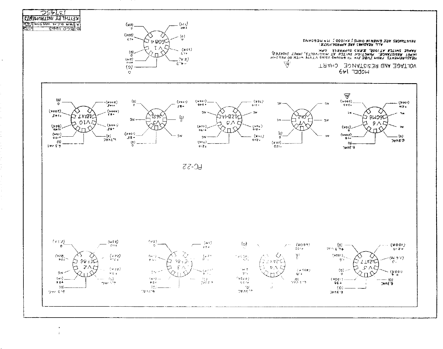
Voltage and Resistance Chart . 5-9
Schematic Diagram. . . . . .
Green Repair and Calibration Form
*
Change Notice . . . . . Last
Page
4- 1
4-l
4- 1
4-2
4-3
5-1
5-l
5-2
5-11
5-13
Page
K
Yellow Change Notice sheet is included only for instrument modifications
affecting the Instruction Manual.
1068R
Page 4
MODEL 149 MILLI-MICROVOLTMETER
INTRODUCTION
SECTION 1. INTRODUCTION
l-l. GENERAL.
The Model 149 Milli-Microvoltmeter is a stable, versatile instrument for measuring
a.
low-level dc signals. It functions as a voltmeter from 100 nanovol s full scale to 100
millivolts.
It also operates as a dc amplifier with gains up to 10 ' for driving recor-
ders.
The low noise level of the Model 149, together with its long-term stability, makes
b.
it ideal for many measurements requiring extreme power sensitivity.
Typical applications include measuring the output from strain gages, thermopilcs,
C.
thermocouples, bolometers, phototubes, ionization chambers, scintillation counters, and
barrier layer cells. Other applications are found in cell studies, measurement of elec-
trochemical potentials, electrolytic corrosion studies, molecular weight analysis and
Hall effect studies.
In addition to its use as a direct indicator of minute potentials and currents, the
d.
Model 149 may also be used as a null detector in Wheatstone or Mueller bridges.
e. An important feature of the instrument is zero suppression up
to
100
times
full
scale in place of the usual more limited meter zero. This permits measurements of small
signals in the presence of large thermal emf's or other masking dc signals.
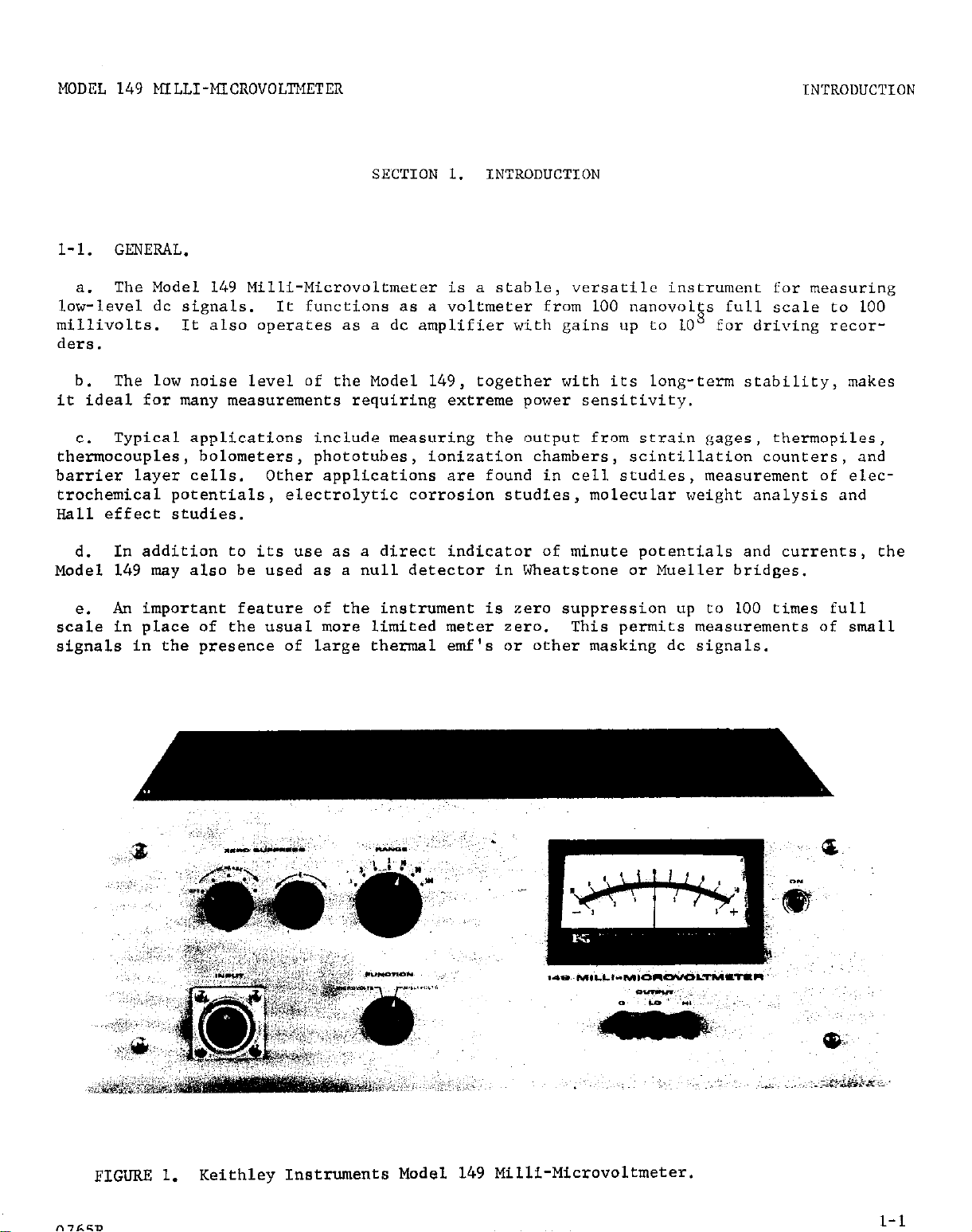
FIGURE 1.
Keithley Instruments Model 149 Milli-Microvoltmeter.
l-l
Page 5
INTRODUCTION
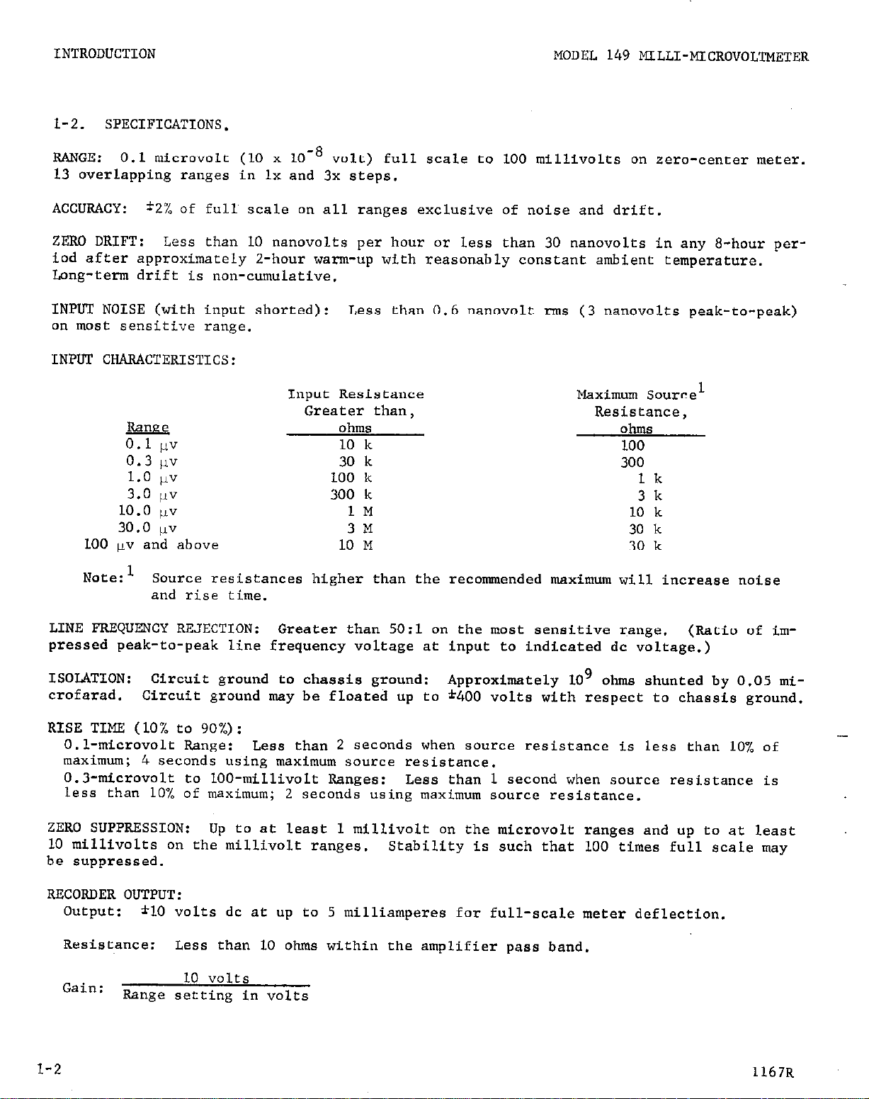
l-2. SPECIFICATIONS.
RANGE: 0.1 micro"olt (10 x 10-8 volt) full scale to 100 millivolts on zero-center meter.
13 overlapping ranges in lx and 3x steps.
ACCURACY: *2% of full scale on all ranges exclusive of noise and drift.
ZERO DRIFT: Less than 10 nanovolts per hour or less than 30 nanovolts in any *-hour period after approximately Z-hour warm-up with reasonably constant ambient temperature.
Long-term drift is non-cumulative.
INPUT NOISE (with input shorted): Less than 0.6 nanovolt rms (3 nanovolts peak-to-peak)
on most sensitive range.
INPDT CHARACTERISTICS:
MODEL 149 MILLI-MICROVOLTMETER
Input Resistance
Greater than,
m
0.1 P"
0.3 ,I"
1.0 &I"
3.0 ,1"
10.0 1"
30.0 )A"
100 pv and above
Note:l
LINE FREQUENCY REJECTION: Greater than 5O:l on the most sensitive r~ange. (Ratio of impressed peak-to-peak line frequency voltage at input to indicated dc voltage.)
ISOLATION: Circuit ground to chassis ground: Approximately 10'
crofarad.
RISE TIME (10% to 90%):
O.l-microvolt Range:
maximum; 4 seconds using maximum source resistance.
0.3-microvolt to lOO-millivolt Ranges: Less than 1 second when source resistance is
less than 10% of maximum; 2 seconds using maximum source resistance.
Source resistances higher than the recommended maximum will increase noise
and rise time.
Circuit ground may be floated up to *400 volts with respect to chassis ground.
mess than 2 seconds when source resistance is less than 10% of
ohms
10 k
30 k
100 k
300 k
1M
3M
10 M
Maximum Source1
Resistance,
ohms
100
300
lk
3k
10 k
30 k
30 k
ohms shunted by 0.05 mi-
-
ZERO SUPPRESSION: Up to at least 1 millivolt on the microvolt ranges and up to at least
10 millivolts on the millivolt ranges. Stability is such that 100 times full scale may
be suppressed.
RECORDER OUTPUT:
output: *lO volts dc at up to 5 milliamperes for full-scale meter deflection.
Resistance:
Gain:
1-2 1167R
Range setting in volts
Less than 10 ohms within the amplifier pass band,
10 volts
Page 6
MODEL 149 MILLI-MICROVOLTMETER
INTRODUCTION
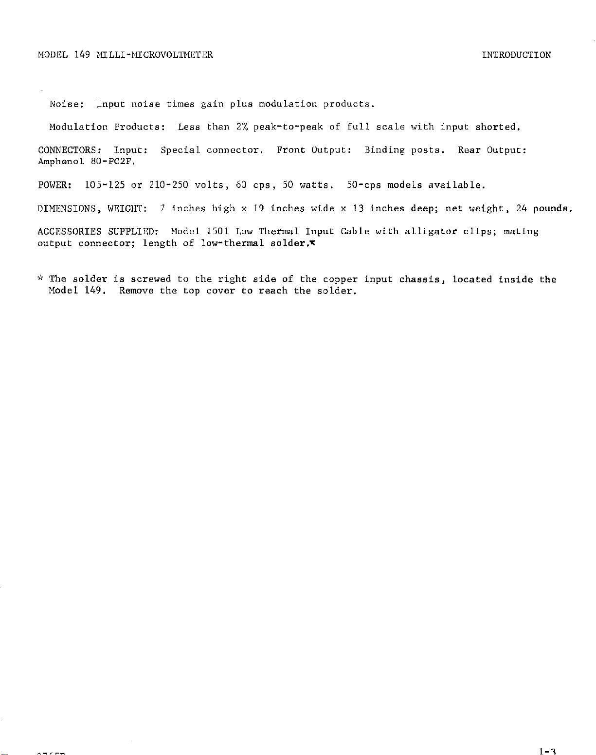
Noise:
Modulation Products:
CONNECTORS:
Input noise times gain plus modulation products.
Less than 2% peak-to-peak of full scale with input shorted.
Input:
Special connector.
Front Output: Binding posts.
Rear Output:
Amphenol 80-PC2F.
POWER:
105-125 or 210-250 volts, 60 cps, 50 watts.
DIMENSIONS, WEIGHT:
7 inches high x 19 inches wide x 13 inches deep; net weight, 24 pounds.
SO-cps models available.
ACCESSORIES SUPPLIED: Model 1501 Low Thermal Input Cable with alligator clips; mating
output connector; length of low-thermal solder.*
-'t The solder is screwed to the right side of the copper input chassis, located inside the
Model 149.
Remove the top cover to reach the solder.
1-3
Page 7
MDDEL 149 KLLI-MICROVOLB
2-1
OPERATION
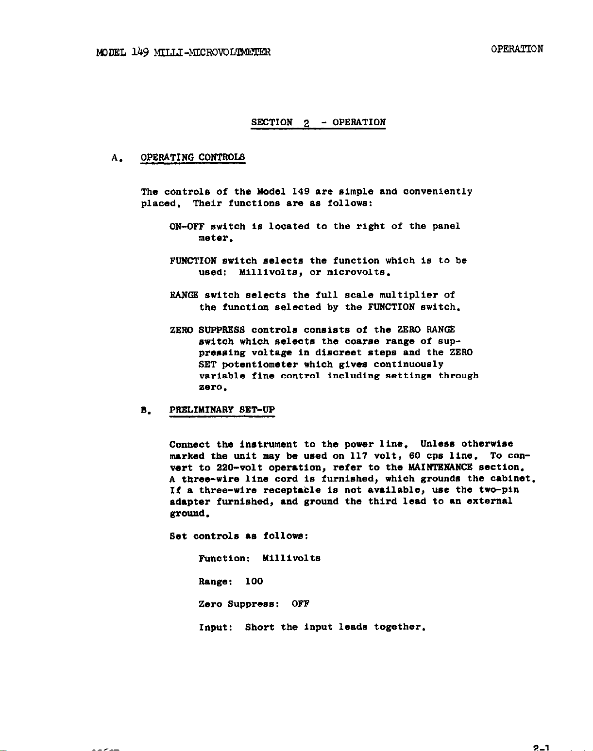
SECTION 2 - OPERATION
A.
OPERATING CONTROLS
The controls of the Model 149 are simple and conveniently
placed.
Their functions are as follows:
ON-OFF switch is located to the right of the panel
meter.
FUNCTION switch selects the function which Is to be
used:
MilliVOltS, Or
!dCrOVOltB.
2AN'm switch selects the full scale multiplier of
the function selected by the FUNCTION switch.
ZERC SUPPiWSS controls consists of the ZERO RANGE
switch which selects the coa.188 range of suppressing voltage in discreet steps and the ZERO
SET potentiometer which gives continuously
variable fine control Including settings through
TieI-0.
PRELIMINARY SET-UP
B.
Connect the instrument to the power line. Unless otherwise
marked the unit may be used on 117 volt, 60 cps line.
vert to 220-volt operation,
refer to the
MAIN'lXK4NC!E
To con-
section.
A three-wire line cord is furnished, which grounds the cabinet.
If a three-wire receptable is not available, use the two-pin
adapter furnished, and ground the third lead to an external
ground.
Set controls *a followa:
Function:
Range :
Millivolts
100
zero suppress: OFF
Input:
Short the input leads together.
Page 8
OPE3ATION
C.
GENERAL PRECAUTIONS
1.
sistance SpeCifiCatYiOg the maximum source resistance for use with
each voltage range is specified.
with source resistance up to ten times greater than those specified,
however, the measurement will suffer from a considerable decrease in
speed of response,
left completely open-circuited,
scale on any range.
Shielding - Since the instrument operates with a modulator
2.
frequency of 120 cps,
up unless it is large enough to overload the amplifier. The pickup
may be a source of difficulty when using the amplifier with high
impedances on ~the more sensitive voltage ranges. In these cases it
is desirable to shield the leads and the sources as completely as
possible. In some cases a simple low-pass filter at the input to
eliminate frequencies of about 1 cps and above will be helpful.
No use is made of an input filter in this instrument since any input
series impedance due to the filter will increase the input noise and
the thermal drift. When operating above ground, the case of the instrument must be grounded.
Source Resistance -
and measuring accuracy.
it is not generally sensitive to 60 cps pick-
KNEL
1n
Section luncler the Input Re-
149
MILLI-MICROVOL-R
Reasonable operation is possible
If the instrument is
the meter will generally drift off
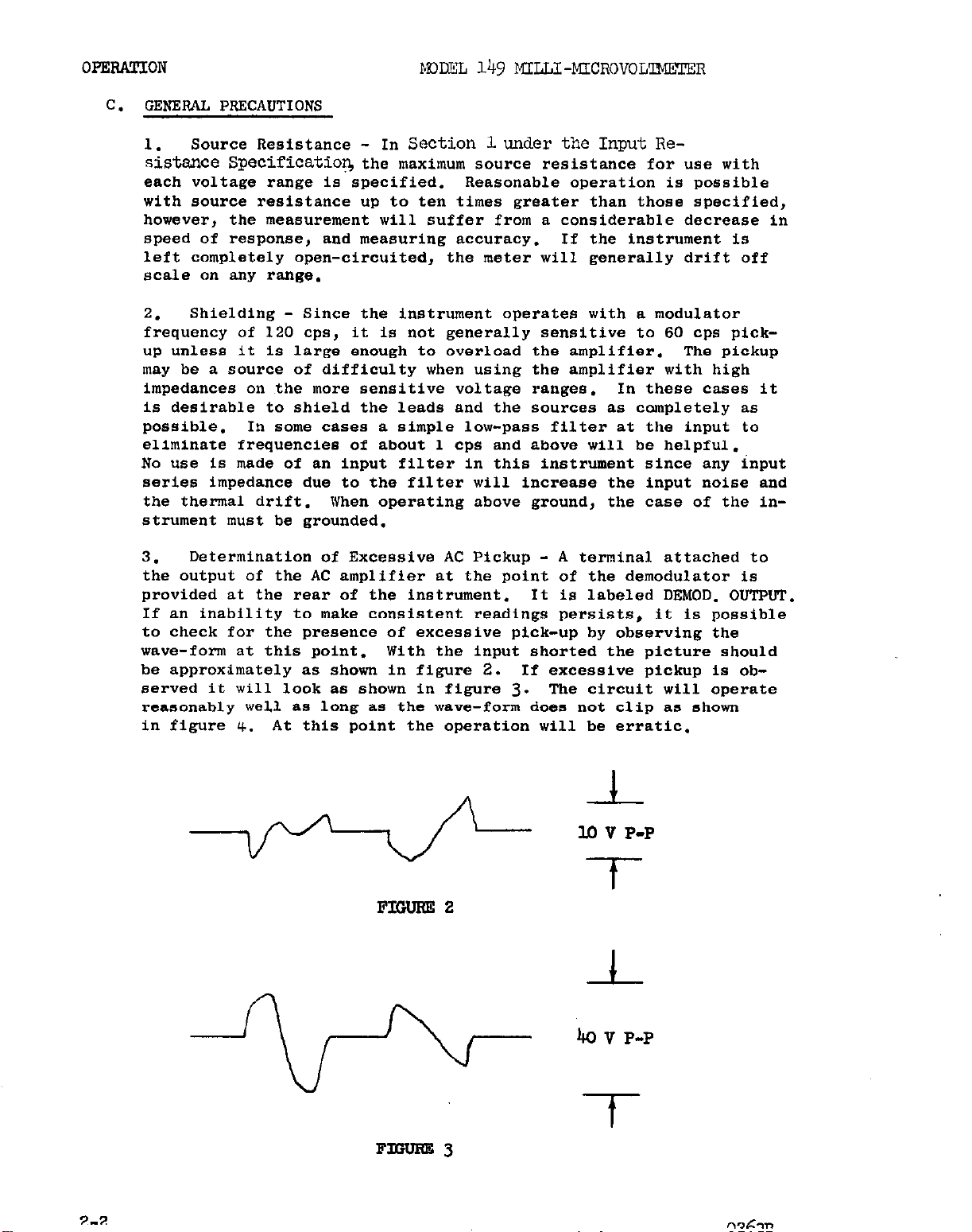
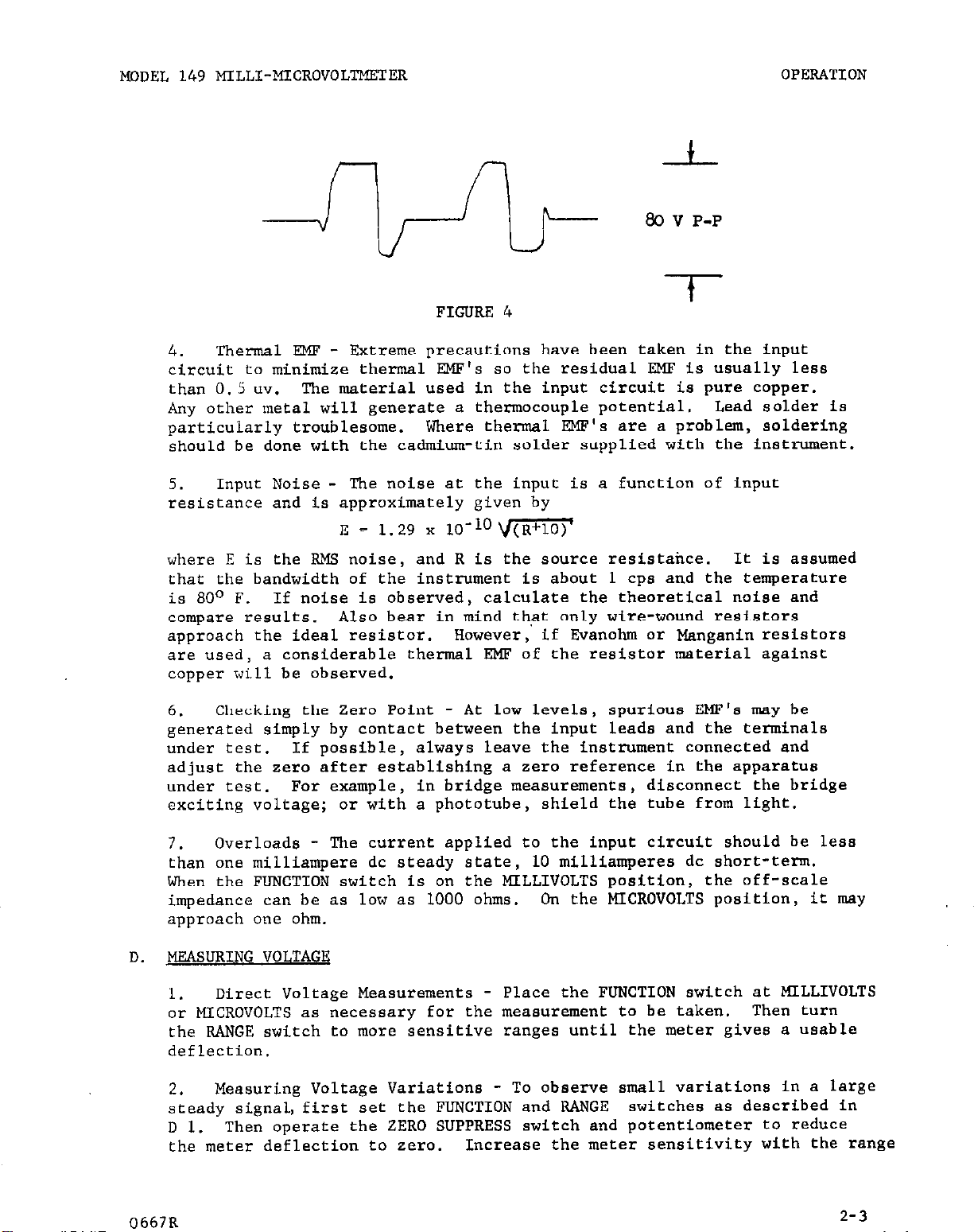
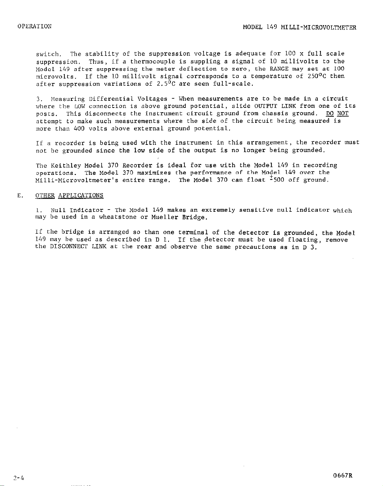
3.
the output of the AC amplifier at the point of the demodulator is
provided at the rear of the instrument. It is labeled DEMOD. OUTPUT.
If an inability to make consistent readings persists, it is possible
to check for the presence of excessive pick-up by observing the
wave-form at this point.
be approximately as shown in figure 2. If
served it will look as shown in figure
reasonably well as long as the wave-form
in figure 4.
Determination of Excessive AC Pickup - A terminal attached to
With the input shorted the picture should
excessive
3.
The circuit will operate
does
not clip as shown
At this point the operation will be erratic.
pickup is ob-
--I.-
lo v P-P
t
FIOUIlE2
c
40 v P-P
t
Page 9
MODEL 149 MILLI-MICROVOLl'METI
Thermal EMF - Extreme precautions have been taken in the input
4.
circuit to minimize thermal EMF's so the residual RMF is usually less
than 0.5 uv.
The material used in the input circuit is pure copper.
Any other metal will generate a thermocouple potential.
particularly troublesome. Where thermal W's are a problem, soldering
should be done with the cadmium-tin solder supplied with the instrument.
Input Noise - The noise at the input is a function of input
5.
resistance and is approximately given by
E = 1.29 x 10-loum
OPERATION
FIGURE 4
Lead solder is
where E is the RMS noise, and R is the source resistaixe. It is assumed
that the bandwidth of the instrument is about 1 cps and the temperature
is 80° F.
If noise is observed, calculate the theoretical noise and
compare results. Also bear in mind that only wire-wound resistors
approach the ideal resistor. However, if Evanohm or Manganin resistors
are used,
a considerable thermal EMF of the resistor material against
copper will be observed.
Checking the Zero Point - At low levels, spurious W's may be
6.
generated
under test.
simply by contact between the input leads and the terminals
If possible,
always leave the instrument connected and
adjust the zero after establishing a zero reference in the apparatus
under test. For example, in bridge measurements, disconnect the bridge
exciting voltage;
Overloads - The current applied to the input circuit should be less
7.
than one milliampere dc steady state,
or with a phototube, shield the tube from light.
10 milliamperes dc short-term.
When the FUNCTION switch is on the MILLIVOLTS position, the off-scale
impedance can be as low as 1000 ohms.
On the MICROVOLTS position, it may
approach one ohm.
MEASURING VOLTAGE
D.
Direct Voltage Measurements - Place the FUNCTION switch at MILLIVOLTS
1.
or MICROVOLTS as necessary for the measurement to be taken.
Then turn
the RANGE switch to more sensitive ranges until the meter gives a usable
deflection,
Measuring Voltage Variations
2.
- To observe small variations in a large
steady signal, first set the FUNCTION and RANGE switches as described in
D 1.
the meter deflection to zero.
Then operate the ZERO SUPPRESS switch and potentiometer to reduce
Increase the meter sensitivity with the range
0667R
2-3
Page 10
OPERATION
MODEL 149 MILLI-MICROVOLTMETER
switch.
suppression.
Model 149 after suppressing the meter deflection to zero, the RANGE may set at 100
microvolts.
after suppression variations of 2.5OC are seen full-scale.
3. Measuring Differential Voltages - When measurements are to be made in a circuit
where the LOW connection is above ground potential,
posts.
attempt to make such measurements where the side of the circuit being measured is
more than 400 volts above external ground potential.
If a recorder is being used with the instrument in this arrangement, the recorder must
not be grounded since the low side of the output is no longer being grounded.
The Keithley Model 370 Recorder is ideal for use with the Model 149 in recording
operations.
Milli-Microvoltmeter's entire range.
E. QTJEJ APPLICATIONS
Null Indicator - The Model 149 makes an extremely sensitive null indicator which
1.
may be used in a wheatstone or Mueller Bridge.
If the bridge is arranged so than one terminal of the detector is grounded, the Model
149 may be used as described in D 1.
the DISCONNECT LINK at the rear and observe the same precautions as in D 3.
The stability of the suppression voltage is adequate for 100 x full scale
Thus,
If the 10 millivolt signal corresponds to a temperature of 250°C then
This disconnects the instrument circuit ground from chassis ground.
The Model 370 maximizes the performance of the Mo$el 149 over the
if a thermocouple is suppling a signal of 10 millivolts to the
slide OUTPUT LINK from one of its
The Model 370 can float -500 off ground.
If the aet~ector must be used floating, remove
NOT DO
7-4
0667R
Page 11
MDEL 149 MILIJ-IWROVOLI~
SECTION 3 - CIRCUIT DESCRIPTlON
CIRCUIT DESCFUFTION
The Model 149 is basically
negative feedback to stabilize the gain and increase the input impedance.
A.
B.
Input Circuit
Zero Stability: The effect of thermal EMF's generated in the input
circuitry is reduced to nearly the vanishing point by the we of only
copper in the input circuit. All aoldar points are made with a low
thermal cadmium-tin solder. The chopper and chopper transformer
employ copper leads. All switching in the input circuit is accomplished
with copper switch.
wound of copper wire. The input connector has solid copper,apringloaded contacts.
The input voltage is applied to the moving arm of a 120 cpa mechanical chopper. The feedback voltage is connected to the primary
center tap of the input transformer. Thus,
is applied first acro88 one half of the primary and then, with phase
reversal, to the other half. This full wave error signal is stepped
up 90 to 1 by the inputtransformer and applied to the grid of
VI, 'a 6084 low-noise pentode.
AC Amplifier
In parallel with the plate load resistor of Vl is a relatively high
Q, 120 cps resonant circuit which narrow the bandwidth and reduce8
spurious signals.
a narrow-band
Critical resistors in the input circuit are
chopper amplifier employing
the difference voltage
V2 and V3, EF86 pentodes, further amplify the chopper error signal
which is then demodulated synchronously by silicon diodes Dl through
m.
To obtain the 120 cps demodulator driving signal, use is made of the
ripple frequency from a bridge rectifier circuit operating from the
line voltage.
driver transformer.
lx2 Amplifier
C.
The demodulated signal is applied to the grid of V4.
V6 form the dc amplifier and.output cathode follower which add
further forward gain to the system and supply output power. Feedback around V4,
demodulator filter capacitor Cl13 by about 1000. This yields the
large equivalent capacitance necessary to smooth the demodulated
error signal.
stages outside the pass band of the whole amplifier are effeCtiVely
degenerated.
The ripple is used in the primary of the demodulator
V4, V5, and
V5 and V6 multiplies the effective capacitance of
Because of the feedback, spurious noise in the dc
Page 12

CIRCUIT DESCRIF'l'ION
D.
Zero Suppression
A low-current
using lo-volt zener diodes.
voltage from
propriate dropping resistors to the feedback point to achieve zero
suppression.
ZERO STJF'F'FESS, while switch 53, which determines the portion feed-
aback, is labeled 7LERO SUPPRESS, OFF-INCREASE.
E.
Other Controls
Two controls are set at the factory
quent attention by the user.
R118 is an internal control marked DC AMP BAL. It is used to zero
the DC amplifier, i.e., to set the output voltage to zero when the
demodulator output is zero. This is not very critical since an "nbalance will simply be fed back to the input to produce a small error signal to correct itself. R127 is marked CAL. This is the var-
iable portion of the meter multiplier resistance to allow for meter-
to-meter sensitivity differences.
power Supply
F.
+10 volt supply is derived from the main dc supplies
Potentiometer Rl54,may be set at any
-10 to +lO volts, this voltage is applied through apThe potentiometer is the front panel control marked
and
should require only infre-
A standard half-wave rectifier followed by an R-C filter is used to
supply unregulated B l and B- to the output cathode follower.
The unregulated B- is regulated to -150 volts in V7, OA2, and is
used for the negative returns for the dc amplifier.
Unregulated B+ is fed to the plate of V6, 12B4A, the series tube in
a 225-volt electronic regulator. The output voltage from this reg"later is divided by R510 and R511 and compared to reference tube
V9, a 5651. The difference signal is amplified by cascade amplifier
VIO, a 12AX7,
tube.
lifier,
This
through a decoupling filter (R176, Cl101 to the second end
and
regulated
applied to the grid-cathode circuit of the series
225 volts supplies B+ directly to the dc amp-
third ac amplifier stages, and through another decoupling filter
(R103, C104) to the first ac amplifier stage.
Regulated B+ and B- also supply currents to the 10 volt zoner diodes
which are used for zero suppression.
This gives two-stage regulation
for these very critical voltages.
Zoner DiodeDllZ regulates the filament voltage of Vl to reduce line
transient effects.
Page 13
MODEL 149 KILLI-KKROVOL'lXl!TER
SECTION
Except for occasional tube or chopper replacement, very little rcalntenance is
required by the Modell@. Components are operated well below rating and solid
state devices are employed where possible to achieve long, trouble-free service.
Certain portions of the input circuit are wired using chopper wire and special
cadmium-tin solder. These special joints are painted red. If, for sny reason,
these joints must be unsoldered or re-soldered, USE ONLY CADMIUM-TIN SOLDER
ANDACO~-~PPEDSOLDERINCIRONWMCBIIA9NEVERBWUSEDWITHaaDINARYLEAD
TIN SOLDER. A mall spool of cadmium-tin solder is supplied with each instrument.
What
trouble-shooting the instrumeut, check to see whether it operates correctly with:
If the difficulty persists, the following systematic procedure may be employed
to determine the fault.
may seem to be circuit failure in the milJ.imicrovoltmeter is quite often
found to be an unusuel condition in the entire test set-up. !l!herefore, before
1. All other circuitry disconnected.
2.
Input shorted (with copper leads).
POwer Line voltage and
3.
4
- MAINTENANCE
frequency
correct.
Reference is made to the Schematic Magrsm
Diagram enclosed at the rear of the manuel.
To begin trouble-shooting, short the input terminals, StrapGto I1) with the
link provided. end switch ZERO suppREsS, OFF-INCREASE to OFF. A Zero offset
of v.1 to 0.4 mlcromlt is
E2ZESSIVEOUTFUTNOISE(INiTlTTpIMINAIs SHORTED)
Because of the vary low signal levels involved, noise in the ac amplifier Is
difficult to trace except by the substitution method. Most likely noise sources
are Vlendthe chopper.
being generated in the dc amplifier or power supply. A stage-by-stage search
~shouldrevealthe source.
~mtetal film resistor.
resistors tend to introduce inductive pickup.
To replace the chopper, unplug the cap atthetop. Frcmtha
14.9, removetheplate covering the areaaroundthe chopper base. Unsolder the
chopper leads.
a
correct connection
the chopper frca the top.
Claen out the lead at the input connector; teg the telminsl for
Replace onlywlththe equivalentreeistor. Win-wound
later.
normal.
If noise persists after replacing the chopper, it is
Very often the noise is generated by RlG2, low noise
Unscrewthe choppermunting screws endlift out
13621~,
and the Voltage-Resistance
bottom
of the&o&l
Page 14

MUNTEWNCE
Insert the new chopper from the
top, putting the wire leads through
the holes. For convenience, place
the No. 2 lead nearest the Model
149 side as shown in Figure
the bottom, secure the chopper with
four No. 4-40 NC-2
proxim&ely 34 In. of teflon tubing
over
other two Gads.
Solder lead No. 2 to the input connector. Insert a shorting bar into
the input connector to push out the
leads enough to facilitate working
on the connection.
lead No. 2 and 2+ in.
screws. Put ap-
5.
over
From
the
M2DEL 149
MIUI-MICRCVOL
NOTEZ
new solid copper tip end low-thermal cadmium solder for all sol&r
connections painted red. This
solder is supplied tith the Model
149.
and mecheacal connections.
Conned lead No. 1 to the red lead
Of trensformer-TR37; connect lead
No. 3 to the blue lead of transformer
m37.
interlock the loops, and solder Do
not cross ortwistthe leads. SliXe
the tubing over the connections.
Twlstshie.l.dleadVaroundchopperleadNo.2asshowninFigure5. Makesure
the end of the shield leed Is free of all-contact.
chopper base.
Use soldering iron with a
Uake sure of goodelectrical
l&k8 loops at the leadends,
Plug in the cap at the top of the chopper.
FIGURR
from the bottom of &Mel 149.
Chopper Replacemnt.
5.
Replacetheplate over the
View
ouTmTNoT2ERo (~0.5mcRo~m)wITRINFuTTwMINnrssRo~
Besurethe?mosuPPmss is
7 of
v4, to glxmld.
control will become very "scratch' but the ad.justment is possible. If this can-
not be done, the dc sqplifler or power supply are at fault. If it ten be set to
zero,
the
trouble n&be
Use the DC AMP RAL control to set the output to Zero. The
set to OFF.
in the ec emplifier or demodulator circuit.
Short the dc amplifier input grid, pin
is
Power
ti -150
the unregulatedB-.
940 volta) a;t the
check the tube pin voltages of VS, Vg, and Vu) to locate the faulty tube or
part.
b. AC Amplifier - Remove the output tube
connectortoground.
ZEIKI SlITandZRRORANUR controls full clockwlse. This puts a large dc error
suppq
on pins 2, 4 or 7 of W.
- B+ should be about
If +225 is not present,
plate pin g
Place the NNCTION switch onMII&IVOLIs, andturnthe
of va.
+225 011 pin 10f va,
If
V7
is not firing, correct the fault in
check for unregulated Dt (about
If the unregulatedB+is all right,
(~6) and
clip pin 1 of the output
and B- should
Page 15

ImDEL 149 PlILLI-MICROVOLI~2XZR
MAINTENANCE
signal across the chopper and input transformer.
for the presence of I20 cps at the primacy of the input trsnsfomers (the
two outside temiuals on the chopper terminal block). Absence of signal
means chopper failure (or much less likely, a shorted or open input transformer).
necessary.
If the I20 cps signal is present, check stage-by-stage throughout the ac
emp.l.ifier, reducing the input signal as desired by backing off the ZERO
FiANGE and/or 2220 SET controls,
d.
Demodulator Circuit -
secondary of the demodulator transformer (at the ends of
The tests outlined above will not suffice to pin-point every fault which
may exist.
In the event that troubles cannot be corrected by these means, or the user
finds it more expedient, the unit may be returned to the factory for repair
and recalibration at a nominal cost.
220-VOLT OPF&lTION
For 220-volt operation the power tramformer primary connections must be changed.
The juktpers connecting black and black-white together and blue and blue-white
should be removed. The blue and black-white leads should be tied together.
Replace the 1.5~ampere fuse (Keithley Part No. W-8) with a 0.75-ampere fuse
(Keithley Part No. m-14).
Listen for audible chopper action and check chopper drive, if
until the failure is discovered.
Check for presence of about 80 volts 2W at the
They should, however, lead to the correction of comon failures.
Use an oscilloscope to check
FLU3
end FtlJ.4).
4-1
Page 16

MODEL 149 MILLI-MICROVOLTMETER
SECTION 5. REPLACEABLE PARTS
REPLACEABLE PARTS
5-1. REPLACEABLE PARTS LIST.
Model 149 and its accessories.
tion,
Number.
contained in Table 3.
5-2.
Part Number,
and those parts coded for Keithley manufacture (80164) must be ordered from Keithley
Instruments, Inc.
describe the part,
ment, Keithley Instruments, Inc.
amp
CbVar
I
CerD
:0lU1
Comp
DCb
ETB
f
hy
a suggested manufacturer,
The name and address of the manufacturers listed in the “Mfg. Code” column are
HOW TO ORDER PARTS.
For parts orders,
a.
the circuit designation and a description of the part.
Order parts through your nearest Keithley distributor or the Sales Service Depart-
b.
include the instrument’s model and serial number, the Keithlcy
In ordering a part not listed in the Replaceable Parts List, completely
its function and its location.
ZXllpere
Carbon Variable
Ceramic, Disc
Commercial
Composition
Deposited Carbon
Electrolytic, tubular
farad
henry
The Replaceable Parts List describes the components of the
The List gives the circuit designation, the part descrip-
the manufacturer’s part number and the Keithley Part
All structural parts
Mfg.
MtF Metal Film
MY
n
P
PM Paper, metal cased
POlY
I-r
”
Var Variable
Manufacturer
Mylar
ohm
pica ( 10-12)
Polvstvrene
. .
micro ( 10m6)
volt
k
M or meg
m milli (10-3)
kilo (103)
mega (106) or megohms
TABLE 2.
w watt
ww Wirewound
wwvar
Abbreviations and Symbols.
Wirewound Variable
5-l
Page 17
REPLACEABLE PARTS
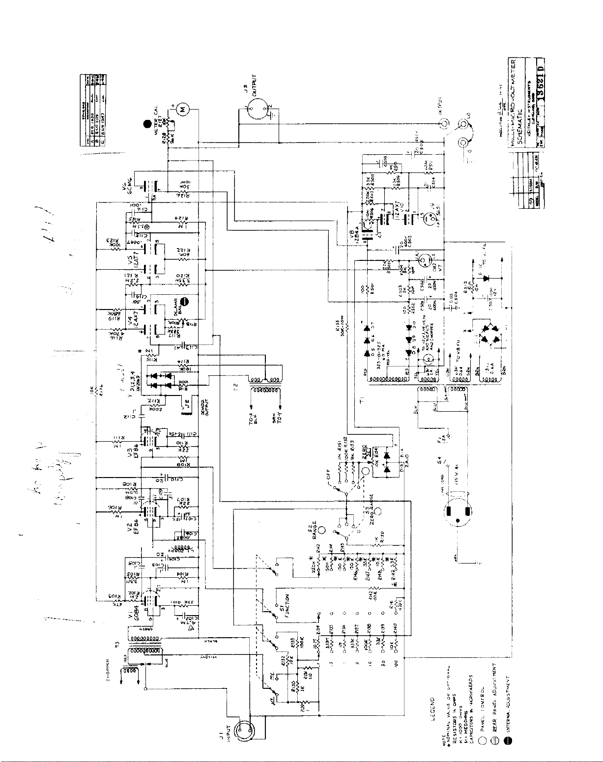
(Refer to Schematic Diagram 13621D for circuit designations.)
MODEL 149 MILLI-MICROVOLTMETER
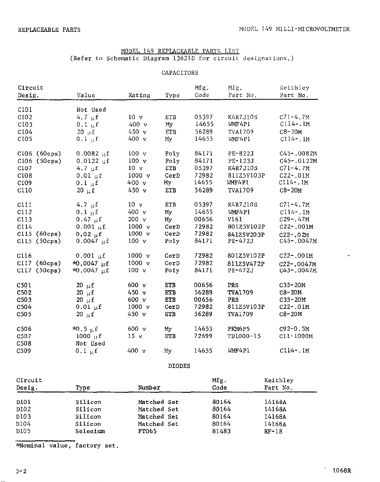
MODEL 149 REPLACEABLE PARTS LIST
CAPACITORS
Circuit
Desig. Value
Cl01
Cl02
Cl03
Cl04
Cl05
Not Used
4.7 (If
0.1 @f
20 pf
0.1 llf
Cl06 (60~~s) 0.0082 ,rf
Cl06 (50~~s) 0.0122 uf
Cl07 4.7 pf
Cl08 0.01 tlf
Cl09
0.1 I.rf
Cl10 20 uf
Cl11
Cl12
Cl13
Cl14
Cl15 (60~~s)
Cl15 (5Ocps)
Cl16
Cl17 (60~~s)
Cl17 (5Ocps)
4.7 pf
0.1 pf
0.47 ,lf
0.001 ,lf
0.02 If
0.0047 IJ.f
0.001 pf
w.0047 pf
w.0047 pf
Rating
10 v
400 v
450 "
400 v
100 v
100 "
10 "
1000 "
400 I!
450 v
10 "
400 v
200 v
1000 "
1000 "
100 "
1000 "
1000 "
100 "
TYPO
ETB
MY
ETB
MY
Poly
Poly
ETB
CerD
MY
ETB
ETB
MY
MY
CerD
CerD
Poly
CerD
CerD
Poly
Mfg. Mfg.
Keithley
Code Part No. Part No.
05397 K4R7JlOS
14655
wMF4Pl
56289 TVA1709
14655
wMF4Pl
84171 PE-822J
84171 PE-123.l
05397
K4R7JlOS
72982 811Z5V103P
14655
wMF4Pl
56289 TVA1709
05397
14655
K4R7JlOS
wMF4Pl
00656 V161
72982 801Z5V102P
72982
841Z5V203P
84171 PE-472J
72982 801Z5V102P
72982
811Z5V472P
84171 PE-472J
C71-4.7M
C114-.1M
C8-20~
C114-.lM
C45-.0082M
C45-.0122M
C71-4.7M
C22-.OlM
Cl14-.lM
C8-20M
C71-4.7M
Cl14-.lM
C29-.47M
C22-.OOlM
c22-.02M
C45-.0047M
C22-.OOlM
C22-.0047M
C45-.0047M
c501
c502
c503
c504
c505
C506
c507
C508
c509
20 pf
20 pf
20 pf
0.01 IJf
20
jLf
w.5 pf
1000 ,lf
Not Used
0.1 pf
600 v
450 v
600 "
1000 "
450 v
600 v
15 "
400 v
Circuit
Desig.
DlOl
D102
D103
D104
TYPO
SiliCOll
Silicon
Silicon Matched Set 80164
Silicon Matched Set 80164 14168~
Number Code Part No.
Matched Set 80164 14168~
Matched Set 80164
D105 Selenium PT065
~~Nominal value, factory set.
ETB
00656
ETB 56289
ETB
00656
CerD 72982
ETB
MY
ETB
MY
56289
14655
72699 TDLOOO-15
14655
DIODES
PRS
TVA1709
PRS
81125V103P
TVA1709
PI(M6P5
C35-20M
CS-20M
C35-20M
C22:.01M
C8-20M
C92-0.5M
Cll-1000M
wMF4Pl
C114-.lM
Mfg. Keithley
14168A
14168A
81483 RF-18
5-2
1068R
Page 18

MODEL 149 MILLI-MICROVOLTMETER
REPLACEABLE PARTS
DIODES (Cont'd)
Circuit
Desig.
DlO6
D107
Dl08
DlO9
DllO
Dill
Dll2
D113
Dl14
D115
D116
Circuit
Desig. Description
FL (115~)
FL (230~)
TYPO
Selenium
Selenium
Selenium PT065 81483
Selenium PT065 81483
Selenium PT065 81483
Selenium Bridge ClB 81483
ZenC?L- lNl589 81483
Zt?lle?Z lN715 12954
ZeIler
Selenium
Selenium
Fuse, slow blow, 1.5 amp, 3 AG (Mfg. No.
31301.5)
Fuse,
Fuse holder (Mfg. No. 342012)
slow blow, 0.75 amp, 3 AG (Mfg. No.
313.750)
NlXllbf?r Code
PT065 81483
PT065 81483
lN715 12954
PT065
PT065 81483
MISCELLANEOUS PARTS
Mfg.
81483
Keithley
Part No.
RF-18
RF-18
RF-18
RF-18
RF-18
RF-7
DZ-4
DZ-22
DZ-22
RF-18
RF-18
Mfg.
Code
75915 FU-8
75915 m-14
75915 FH-3
Keithley
Part No.
Gl (60~~s)
Gl (50~~s)
Jl
---
52
53
---
_--
--__-
LL
M
---
---
Chopper, Frequency Doubling
Chopper, Frequency Doubling
Receptacle Assembly, INPUT
Plug, Special, Mate of Jl
Jack, Telephone, DEMOD. TEST (Mfg. No. 275)
Receptacle, Microphone, OUTPUT (Mfg. No.
80-PC2F)
Plug, Microphone, Mate of 53 (Mfg. No.
80-MC2M)
Binding Posts (Z), OUTPUT, black (Mfg.
No. DF21BC)
Binding Post, OUTPUT, red (Mfg. No.
DF21RC)
Shorting Link (Mfg. No. 938-L)
Choke, 200 hy
Meter
Meter Lamp (Mfg. No. 323)
Cord Set,
6 feet (Mfg. No. 4638-13)
80164
80164
80164 12450B
80164 13011B
71002 CS-65
02660
02660 cs-33
58474
58474
24655 BP-6
80164
80164
08804
93656
cv-2
cv-3
CS-32
BP-11B
BP-11R
CH-1
ME-14
PL-1
co-5
171/,P
5-3
Page 19

REPLACEABLE PARTS
MODEL 149 MILLI-MICROVOLTMETER
MISCELLANEOUS PARTS (Cont'd)
Circuit
Des@. Description
Cable Clamp (Mfg. No. SR-SP-1)
Sl
---
--s2
Rotary Switch less components, FUNCTION
Switch Assembly with components, Function
Skirted Knob,
Rotary Switch less components, RANGE
Switch Assembly with components, Range
Skirted Knob, Range Switch
s3
Rotary Switch less components, ZERO SUPPRESS,
Range
---
Switch Assembly, Zero Suppress, Range
Skirted Knob,
---
Skirted Knob, Zero Suppress Set Potentiometer
Function Switch
Zero Suppress Range Switch
Mfg.
Code
28520 cc-4
80164 SW-161
80164 13728B
80164
80164 SW-96
80164 13727B
80164 la-10
80164 SW-58
80164
80164 RN-11
80164 KN-17
54 Toggle Switch, DPDT, ON (Mfg. No. 20905-FR) 04009
Tl Transformer, Power 80164
T2 Transformer, Filament
80164 TR-26
T3 Transformer, Chopper 80164
Keithley
Part No.
la-11
13726B
SW-14
TR-36
TR-37
Circuit
Desig. Value Rating
RlOl 33 kn
R102
2Mn
R103 4 7 I~(~?
R104 1 m
R105 3.3 MO
RlO6 1 HT:
R107 22 IC?
R108 3.3 M1
R109 1 It-!
RllO 22 I<<?
Rlll 1 M:
RLl2 200 kc:
R113 100 ki!
R114 100 k:!
Rl15
"1 ti:i
R116 470 kq
R117 333 k?
R118 500 kc:
lO%, l/2 w
0
l/,, 1 w
lO%, l/2 w
l%, l/2 w
lO%, l/2 w
l%, l/2 w
lO%, l/2 w
lO%, l/2 w
l%, 112 w
lO%, l/2 w
I%, l/2 w
l%, l/2 w
l%, l/2 w
l%, l/2 w
l%, l/2 w
l%, l/2 w
l%, l/2 w
10%, 2 w
RESISTORS
Mfg. Mfg.
TYPO
Code Part No.
camp 01121 EB
MtF 07716
Comp
01121 EB Rl-47K
Deb 79727
camp 01121
DCb
79727 CFE-15 R12-1M
camp 01121
camp 01121
MEF R44-2M
CFE-15 Rl2-1M
EB Rl-3.3M
EB Rl-22K
EB Rl-3.3M
Keithley
Part No.
Rl-33K
DCb 79727 CFE-15 R12-1M
camp 01121
DCb
DCb
DCb
DCb
DCb
DCb
DCb
CbVar
79727
79727
79727
79727
79727
79727
79727
01121
EB
CFE-15 Rl2-1M
CFE-15
CFE-15
CFE-15 R12-100K
CFE-15 R12-1M
CFE-15 Ri2-470K
CFE-15
.J RP5-500K
Rl-22K
Rl2-200K
R12-100K
R12-333K
*?jomi.nal value, factory
j-4
set.
1264R
Page 20

MODEL 140 IIILLI-MICROVOLTMETER
REPLACEABLE PARTS
RESISTORS (Cont'd)
Circuit
Desig.
R119
R120
R121
R122
R123
R124
R125
R126
R127
R128
R129
R130
R131
R132
R133
R134
Rl35
Value Rating
680
kn
3.33 m
2. 2 M"
62
k!?
100 kr2
1.3 Mri
1 Mn
30 kfi
10 kn
95.3 kc
12
1 kn
111 ?
10 kR
100 kc
10 m
3.33 m
l%, l/2 w
l%, l/2 w
l%, l/2 w
l%, l/2 w
l%, l/2 w
l%, l/2 w
l%, l/2 w
5%,
lO%, 2 w
l%, 1 w
1%
1%
lf4%, l/3 w
5%
lO%, l/2 "
l%, 112 w
l%, l/2 w
10 w
TYPO
DCb
DCb
DCb
Mfg.
Code Part No.
79727 CFE-15
79727 CFE-15
79727
Mfg.
CFE-15 R12-2.2M
DCb 79727 CFE-15
DCb
79727
CFE-15 Rl2-100K
DCb 79727 CFE-15
Keithley
Part No.
R12-680K
RlZ-3.33M
R12-62K
R12-1.3M
DCb 79727 CFE-15 R12-1M
ww
WWVar
MtF
ww
63743
71450
07716
80164
10F
WP
CEC
R5-30K
RP9-1OK
R94-95.3K
'.*RlE-18-1
Special
ww
80164
'.+cR18-18-1K
Special
wwenc
01686
7010
R105-111
Special
ww
80164
R18-18-10K
Special
camp
DCb
DCb
01121 EB Rl-LOOK
79727 CFE-15 Rl2-1OM
79727 CFE-15 R12-3.33M
RI36
R137
R138
R139
R140
R141
R142
R143
R144
R145
R146
R147
R148
R149
R150
Rl51
Rl52
R153
R154
R155
1Kl
333
k<l
100 kn
33.2
9.9 kn
220 kn
100 kn
II%
100 kn
9 kn
10 kn
30
kn
kn
0.5%, l/2 w
0.5%, l/2 w
0.5%, l/2 w
0.577, l/2 w
0.5%, l/2 w
lO%, l/2 w
lO%, l/2 w
lO%, l/2 w
lO%, l/2 w
lO%, l/2 w
lO%, l/2 "
lO%, l/2 w
lO%, l/2 w
lO%, l/2 w
1%, l/2 w
l%, l/2 w
l%, l/2 w
l%, l/2 w
3%, 5 w
5%,
10 w
MtF
MtF
07716
07716
CEC
CEC
MtF 07716 CEC
MtF
07716
CEC
MtF 07716 CEC
camp
DCb
01121
80164
EB
Special
camp
Comp
Comp
Comp
Comp
01121 EB
01121 EB Rl-150K
01121
EB
01121 EB Rl-150K
01121 EB Rl-33K
camp 01121 EB
Comp
DCb
DCb
DCb 79727
DCb
WWVsr
ww
01121 EB Rl-3.3K
79727 CFE-15 R12-1K
79727 CFE-15
CFE-15
79727 CFE-15
73138 A
63743
10F
R61-1M
R61-333K
R61-100K
R61-33.2K
R61-9.9K
Rl- 220K
R38-
1OOK
RI- 1.5M
Rl-150K
Rl- 3.9K
R12-1M
R12-100K
R12-9K
RP4-
10K
R5-30K
JrNominal vali.le, factory set.
WrR129 and R130 are matched to l/2%.
Order a8 a pair.
Page 21

REPLACEABLE PARTS
RESISTORS (Cont'd)
Circuit Mfg. Mfg.
Desig. Value Rating
R176
R501
R502
R503
R504
R505
R506
R507
R508
R509
R510
R511
R512
10 Ia
too ‘,!
100 R
5 kn
5 kr!
22 kO
10 m
220 ICC
33 kn
33 k0
Ii%
600 kil
10 (2
lO%, l/2 w
lO%, 2 w
lO%, 2 w
5%, 10 w
5%, 10 w
lO%, 2 w
lO%, l/2 w
l%, l/2 w
lO%, 112 w
lO%, l/2 w
lO%, l/2 w
l%, l/2 w
l%, 5 w
TYPO
Code
Comp 01121
Comp 01121
Comp 01121
ww 94310
ww 94310
Comp 01121
camp 01121
DCb 79727
Comp 01121
camp 01121
Comp 01121
Deb 79727
ww 91637
Part No.
IIB
HB
FR-10
FR-10
HB
EB
CFE-15
EB
EB
EB
CFE-15
RS-5
VACWM TUBES
Circuit
Desig.
Number
Mfg.
Code
Keithley
Part No.
Keithley
Part No.
Ill- 1OK
R3-100
R3-100
R5-5K
R5-5K
R3-22K
RI-1OM
R12-220K
Rl-33K
Rl-33K
Rl-1M
Rl2-600K
R4A-10
Vl
v2
v3 ;Ld"kEFB
~:*<6084 80164 ~V-6084/E80~
;+k~t36
6
80164
80164 Ev-EF86/6267
EV-EF86/6267
V4 +&.h 7025 80164 EV-ECC83/7025
v5
V6
~~~lZAT7 80164
EZV-12AT7
>'&6OM6 80164 EV-6CM6
v7 "(,A 2 80164 BV-OA2
V8
v9
12B4A
85599 EZV-12B4A
+'dcCK5651 80164 EV-CK5651
VlO 7025 73445 EV-ECC83/7025
MODELS 1483. 1484 REPLACEABLE PARTS LIST
Description
Mfg.
Keithley
Quantity Code Part No. Kit Model
Used on
Crimp Tool for Copper lugs 1 80164 TL-1 1483
l/8 Nylon Screws 50 80164 --- 1483, 1484
#8 Nylon Hex Nuts 50 80164 ___ 1483, 1484
Copper Bolt-on Lugs 100 80164 17340 A 1483, 1484
Copper Spade Lugs 100 80164 17339 A 1483, 1484
Copper Hook Lugs 100 80164 17336 A 1483, 1484
Copper Splice Tubes 100 80164 17338 A 1483, 1484
Low-Thermal Cadmium-Tin Solder 10 feet 80164 --- 1483, 148b
Copper Alligator Clips (Mfg.
No. 6005) 10 76545 AC-9 1483, 1484
?~w~~Specially aged tubes.
5-6 1267~
Page 22

MODEL 149 MILLI-MICROVOLTMETER
MODELS 1483, 1484 REPLACEABLE PARTS LIST (Cont'd)
REPLACEABLE PARTS
Descriotion
Shielded Cable 10 feet 80164 SC-5 1483, 1484
Insulated 1b2.0 Copper Wire LOO feet 80164 ws- 1 1483, 1484
Non-metalic Abrasive 3 pads 80164
MODEL 1491 REPLACEABLE PARTS LIST
Description
End Frames
Fastener, Thumbscrew
Feet, Rubber
Attaching Parts
Machine Screw, No. 6-32lJNC-2x1/2, Rd Hd, Phillips
Hex Nut, No. 6-32UNC-2 4 Corn1 ---
__________- -
Machine Screw, No. 8-32UNC-2x5/16, Rd Hd, Phillips
Quantity
Mfg.
Code
No. Required
Per Model
2
4
4
4 Corn1 ---
4 Cod ---
Keithley
Part No.
LJ774A
Mfg.
Code Part No.
80164 L312OC
80164 FA-9
80164 FE-2
Used on
Kit Model
1483, 1484
Keithley
BODEI. 1501 REPLACEABLE PARTS LIST
Mfg.
Description
Plug Assembly
CabIe, 48 inches, Vinyl, shielded 86696 SC-5
Alligator Clamps, two (Mfg. No. 6OC5)
MODEL 1502 REPLACEABLE PARTS LIST
Description
Plug Assembly
Cable, 10 feet, Vinyl, shielded 86696 SC-5
DO011 Sylvania Electric Products, Inc.
Buffalo Operations of Sylvania
Electronic Systems
Buffalo, N. Y.
00656 Aerovox Corp.
New Bedford, Mass.
01121 Allen-Bradley Corp.
Milwaukee, Wis.
1
TABLE 3 (Sheet 1).
for Manufacturers, Cataloging Handbook H4-1.)
1264R
Code List of Suggested Manufacturers. (Based on Federal Supply Code
02660 Amphenol-Borg Electronics Corp.
Broadview, Chicago, Illinois
04009 Arrow-Hart and Hegeman Electric Co
Hartford, Corm.
05397 Kemet Co.
Cleveland, Ohio
07716 International Resistance Co.
Burlinnton. Iowa
Code Part No.
80164 1301LB
76545
Mfg.
Code Part No.
80164
Keithley
AC-8
Keithley
L301LB
5-7
Page 23

REPLACEABLE PARTS
MODEL 149 MlLLI-MTCROVOLTMETER
38804
12954
14655
24655
28520
$4655
56289
58474
53743
71002
71450
72982
Lamp Metals and Components
Department G. E. Co.
Clawland, Ohio
Dickson Electronics Corp.
Scottsdale, Ariz.
Cornell-Dubilier Electric Corp.
Newark, N. .J.
General Radio Co.
West Concord. A&ass.
Heyman >ffg. Co.
Kenilworth, ?J. .J.
Ohmite Mfg. Co.
Skokie, ILL.
Sprague Electric Co.
North Adams, Mass.
Superior Electric Co., The
Bristol, Corm.
Ward Leonard Electric Co.
Mount Vernon, N. Y.
Birnbach Radio Co.
New York, N. Y.
CTS Corp.
Elkhart, Ind.
Erie Technological Products, Inc.
Erie, Pa.
75915
76545
79727
80164
81453
81483
83125
83330
84171
85599
86684
Littelfuse, Inc.
Des Plain&, Ill.
Mueller Electric Co.
Cleveland, Ohio
Continental-Wirt Electronics Corp.
Philadelphia, Pa.
Keithley Instruments, Inc.
Cleveland, Ohio
Raytheon Co.
Industrial Components Div.
Industrial Tube Operation
Newton, Mass.
International Rectifier Corp.
EL Segundo, Calif.
General Instrument Corp.
Capacitor Division
Darlington, S. C.
Smith, Herman H., Inc.
Brooklyn, N. Y.
Arco Electronics, Inc.
Great Neck, N. Y.
Tube Department G. E. Co.
Schenectady, New York
RCA Electron Tube Division
of Radio Corp. of America
Harrison, N. 3.
I
73138
Helipot Division of
Beckman Instruments, Inc.
Fullerton, Calif.
73445
Amperex Electronic Co.
Division of North American
Philips Co., Inc.
Hicksville, N. Y.
75042
International Resistance Co.
Philadelphia, Pa.
CABLE 3 (Sheet 2).
Code List of Suggested Manufacturers.
for Manufacturers, Cataloging Handbook H4-1.)
5-8
86606
91637
93656
94310
99942
Radix Wire Co.
Cleveland, Ohio
Dale Electronics, Inc.
Columbus, Nebr.
Electric Cord Co.
Caldwell, N. J.
Tru Ohm Products
Memcor Components Division
Huntington, Ind.
Hoffman Electronics Corp.
Semiconductor Division
EL Monte. Calif.
(Based on Federal Supply Code
1264R
Page 24
Page 25

Behnulry 3, 1965
MlDEL 149 XEU-M
a1-2, Change the firat
After
in any
approdmstely 2-hour warm-up within 0.01 ~crovolt per
&hour period
with
sentence of
relatively constant ambient
pana. Cbanga to the follcwingt
Circuit
DeaiE&
Dl13
WPO
zener
0114 zoner
12954 la
die
nmmfactumr cod41 for M&eon Bloctronica Corp.,
Nladmr
119715
lN715
the SZMILITY Specific;ition
hour or
temperatures.
Mfs.
Keithley
Code Rart No.
12954
12954 m-22
Dz-22
Scottsdale,
to
the folkwing:
0.03 microvolt
Ma.
Page 26

CNANGB NOTICE
April
15, 1965
J&&&& Qangs to the followin?i:
to
1000 "
.02.
Cl15 (60 cpa)
m*
&mge the
value
0.02
&f
of Cl15
Car3
WDET.149 MILY.I-Xt~OLl3f=~
72902
84lZ5V203P
c22-.02M
Page 27

MB Quylo tb
fCratrentuaue
Inpuagraplt 4to road;
4. lltotnml B&trm
thortmt
a Cbango to
AUF's 130 the roaidaal BEC Lo wually leas than 0.5 uv.
-
precoutio~
the follawingr
cfraiit
Do&g.
cl04
Cl10
z:
l?~lItO
z ":
20 ;P
2l.pf
mtbs
450 v
450 v
4sOv
4% v
m* aougo tc rho follow%Dgr
urcdt wt.
aofJ&
v4
VI0
Nther
-7025
-025
code
80164
80164
mg
lsavo been taken in the input circuit to midmlzm
lus
z
Em
56289
56289
56289
56289
TVA1709 ca-20x
ToA c8-20x
TVA1709
TVA1709
K&t&lap
Part
No.
Ew-&xxl33/702s
m-lma3/702s
aurlg~tlunuldmr0f lf4andvxo to’7025
*wspeotallyagod tabu.
Page 28

liuvdmr
3, 1966
lwNLlA9xxL7AI~
PaNo I-2. aut&$o
to
ciroutt
lhrl&
Cl05 0.1 rrf
Cll2
cSo9
value
0.1 pf
0.1 $.4f
the Wlorrkyr
aat-8
4OOV
4OOV
4oov
nv
z
w
146SS
lA6s5
14655
Wi.
part
NXP
NW
NXP
x0.
4Pl
4Pl
4Pl
lWth1.y
POrtlb.
Cllb.ln
Club.ln
ClU-.lx
Page 29
/
~..~~_~.._~~.~~~~ ~.~~_ _._,
r’ ‘~i%inbexr~6 .~..I967 ‘~ ..i.
CHANGE NOTICE
MODEL 149 MILLI-MICROVOLTMETER
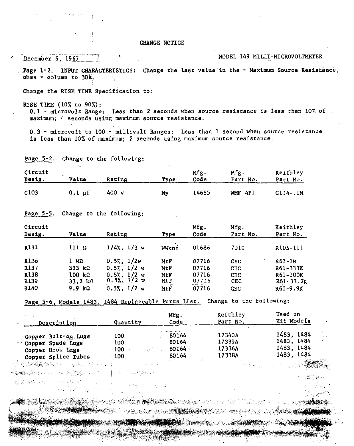
‘, .Page l-2.
ohms -
INPU’l.~CH@ACTERISTICS:
column to 30,s
Change the last value-in the - Maximum Source Resistance,
Change the RISE TIME Specification to:
RISE TIME (10% to 90%) :
0.1 -
microvolt Range:. Less than 2 seconds when sourceresistance is less than 10% oft
maximum; 4 seconds using maximum source resistance.
- micro& to 100
0.3
- millivolt Ranges:
Less than 1 second when source resistance
is less than 10% of maximum; 2 seconds using maximum source resistance.
Page 5-2. Change to the following:
circuit
Des&. Value
Cl03 0.1 (If
Page 5-5.
Change to the following:
circuit
.Desig.
Value
Rating Type
400 ”
MY
Rating Type Code
Mfg.
code
14655
Mfg.
Mfg.
Part NO.
WMF 4Pl C114-.lM
Mfg.
Part No. Part No.
Keithley
Part NO.
Keithley
R131 111 n
R136
R137
1 MO 0.5%, 1/2w
333 kfl
R138 100 kfl
Rl39 33.2 kfl
R140 9.9 kfl
l/4%, l/3 w
0.5%, l/2 w
0.5%,~ l/2 w
0.5%, l/2~Y ~~, _~
0.5%, ~i/2 w
went 01686
MtF
MtF
MtF
MtF 07716
MtF 07716
Page 5-6, Models 1483, 1484 Replaceable Parts List.
Description
Quantity
._ ~~~... ..~~
Copper Bolt -on,,Lugs
~’ copper Spade Lugs
copper Hook Lugs
Copper Splice Tuties
,,:‘: ,;‘;;,,~ .:!.~;~+ ,., ‘,,~ ~~ ,_, ,,,, ,, ,.,
~‘;i,~..~,:,,*:,~,-.r”,l,‘~, :~ ,, ,;. i ‘~,,~ ,.‘~‘,‘,‘~‘:.; ,,;, :, :
100
100
100 ‘. ~.-
100.
,I~
,;& ::2
.,e-3034
~‘,~ ~,
‘.Y
7010
07716
07716
07716
CEC R61-1M
CEC
CEC
CEC
~~CEti
Change to the following:
Mfg.
Keithley
code Part No.
17340A
80164 17339A
80164
-80164
17336A
17338A
R105-111
R61-333K
R61-100K
R61-33.2K
R61-9.9K’~
Used on
Kit ModeIs
1483. 1484
1483, 1484
1483, 1484
1483, 1484
~. ~?YJ@@y?;,
.~.~.Z~~. i,
,~<T i;l;_~
Page 30
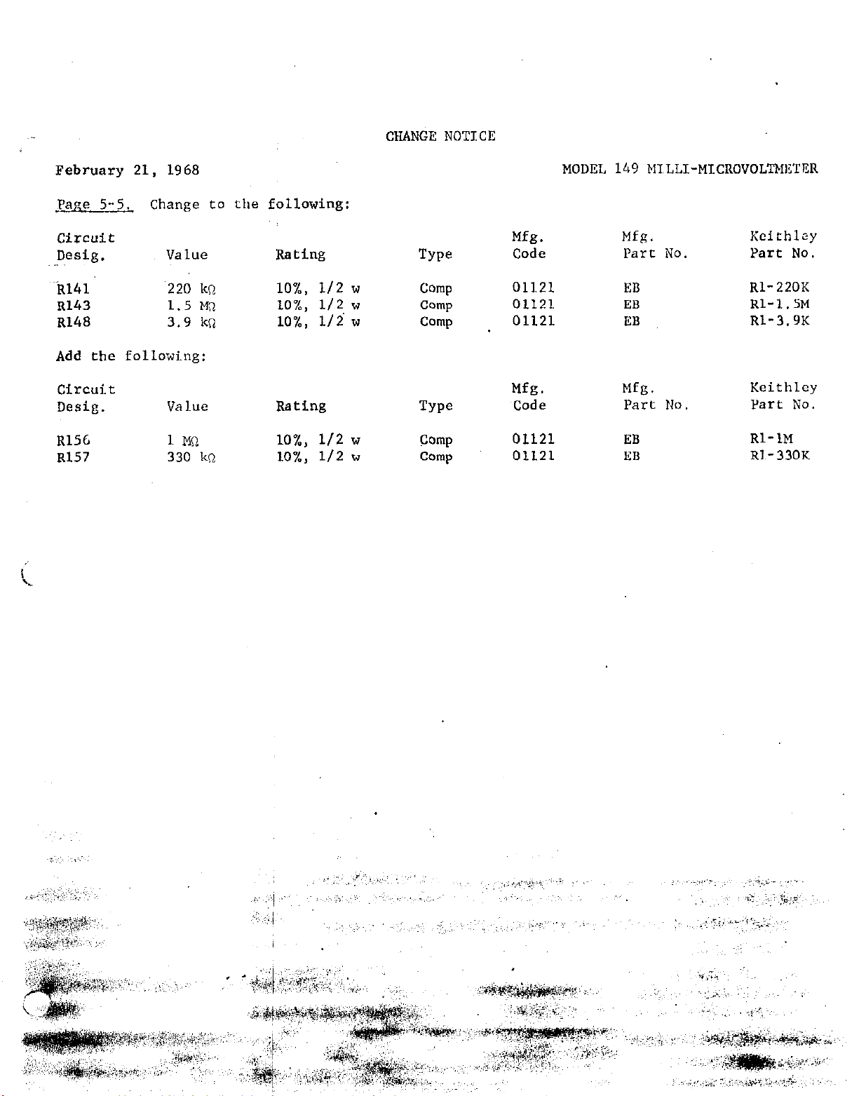
CHANGE NOTICE
February 21, 1968
Pane 5-5.
circuit
twig.
Change to the following:
Value
&41 220 kn
R143
~148
1.5 Ma
3.9 kn
Add the following:
Circuit
Desig.
R156
Rl57
Value
1 MO
330 kn
Rating
lO%, l/2 w
lO%, l/2 w
lO%, l/i w
Rating
lO%, l/2 "
lO%, l/2 w
TYPO
Comp
Camp
Comp
TYPO
Camp
Comp
Mfg.
Code
01121
01121
01121
Mfg.
Code
01121
01121
MODEL 149 MTLLI-MICROVOLTMl3TER
Mfg.
Part No.
EB
ED
EB
Mfg.
Part NO.
EB
EB
Kcithlzy
Part No.
Rl-220K
Rl-l.SM
Rl-3.9K
Keithley
Part No.
Rl-1M
Rl-330K
Page 31

. .
,&$ril 16, 1969
&$;~e s-2
.
Change to the following:
Circuit
Desig
D105
D106
mea
Type
Silicon
Silicon
Silicon
Dl.09 Silicon
.
CNANGE NOTICE
MODEL 149 MILLI-MICROVOLTMETER
Mfg. Keithley
Number
J&J3256
IX3256
IN3256
Ui3256
-.-
Code
Part No.
02735 W-22
02735 RF-12
02735 ' RF-22
02735
RF-22
Page 32
 Loading...