

Keith RUNNING FLOOR II DX, RUNNING FLOOR II DXE, KRFII-3, KRFII-4, KRFII-3.5 Owner's And Operator's Manual
RUNNING FLOOR II
KEITH Manufacturing Co.
www.KeithWalkingFloor.com
World Headquarters
Toll-Free: 800-547-6161
Phone: 541-475-3802
Fax: 541-475-2169
®
DX/DXE
10002001
OWNER / OPERATOR MANUAL
Original Instructions
©2018 KEITH Manufacturing Co. All Rights Reserved. KEITH, KEITH logo and WALKING FLOOR are registered trademarks of KEITH
Manufacturing Co. Equipment manufactured by KEITH Manufacturing Co. is protected by numerous patents both domestic and foreign.
DOC06179 Rev. B

OWNER / OPERATOR MANUAL RUNNING FLOOR II® DX / DXE
Table of Contents
Introduction iii
Declaration of Incorporation iv
KEITH WALKING FLOOR® Drive Unit Limited Warranty v
Warranty Registration Card vii
1.0 Safety 1
1.1 General Safety 1
1.1.1 Intended Function and Expected Use: 1
1.1.2 Improper Use 1
1.1.3 Training 2
1.1.4 Personal Protective Equipment 2
1.1.5 Airborne Noise Emission 2
1.1.6 Temperature 2
1.1.7 Lighting 3
1.1.8 Movement Around the System 3
1.1.9 Hydraulic Oil Safety 3
1.2 Design / Installation Safety 3
1.2.1 Kit Components 3
1.2.2 Installation 3
1.2.3 Danger Zones 3
1.2.4 Electric Components and Installation 4
1.2.5 Hydraulics 4
1.2.6 Controls 4
1.3 Marking of Machinery 5
1.3.1 Safety Decals 5
1.3.2 Serial Plates 9
2.0 Specications 10
2.1 Hydraulic Drive Unit 10
2.2 General Wet Kit Specications 11
2.3 Floor to Wet Kit Connection Diagram 12
3.0 Operation 13
3.1 How It Works 13
3.2 Oil Flow Diagrams 14
3.3 Component Location Guides 16
3.4 Drive Component Identication 19
3.5 Start-Up Operation 20
3.5.1 Before initial start-up: 20
3.5.2 After initial 6 working hours OR rst week of operation: 20
3.6 Pre-Trip Checklist 20
3.7 Manual Controls 21
3.8 Electric On/Off, Manual Load/Unload - Wireless Remote Control 22
3.8.1 4 Channel Remote Control Transmitter 22
3.8.2 4 Channel Remote Control Receiver 24
i DOC06179 Rev. B

OWNER / OPERATOR MANUAL RUNNING FLOOR II® DX / DXE
3.9 Electric On/Off & Electric Load/Unload - Wireless Remote Control 25
3.9.1 4 Channel Remote Control Transmitter 25
3.9.2 4 Channel Remote Control Receiver 27
3.10 Electric On/Off & Electric Load/Unload - Cabled Remote Control 28
3.11 Manual Override of Electric Controls 29
4.0 Maintenance 31
4.1 Life Extending Conditions 31
4.2 Preventative Maintenance 31
4.2.1 Monthly Service (25 operating hours) 31
4.2.2 6-Month Service (150 operating hours) 31
4.3 Bolt Torque Requirements 32
4.4 Cross-Drive Wear Component Diagram 33
4.5 Flooring Wear Component Diagrams 34
5.0 Troubleshooting 35
5.1 Check List 35
5.2 Problem / Solution - Troubleshooting 35
5.3 Adjustments & Repairs 35
5.4 Technical Support 35
6.0 Contact Information 36
ii DOC06179 Rev. B
OWNER / OPERATOR MANUAL RUNNING FLOOR II® DX / DXE
Introduction
We at KEITH Manufacturing Co. are very happy that you have decided to equip your trailer with the KEITH
RUNNING FLOOR II® DX/DXE unloading system. We take great pride in the fact that we manufacture the
®
simplest and lowest maintenance self-unloading system available. Installing the KEITH
®
DX/DXE unloader in your trailer provides you with the versatility to load or unload virtually any type of
II
RUNNING FLOOR
material.
®
The following pages contain information on the operation of your KEITH
RUNNING FLOOR II® DX/DXE
unloader.
In addition, we have provided general information on the type of hydraulic wet kit that will be needed on your
tractor. Please contact a KEITH Manufacturing Co. representative or visit our website www .KeithWalkingFloor.
com for more specic recommendations regarding pumps, lters and pressure relief valves and approved
equivalent equipment. It is critical to adhere to the outlined hydraulic wet kit specications. Failure to follow
the guidelines concerning required operation pressures can lead to your system operating improperly.
®
Please review the entire manual before operating the KEITH
RUNNING FLOOR II® DX/DXE unloading
system. If you have any questions or concerns, do not hesitate to contact our factory toll-free at 800-5476161 or via email at TechDept@KeithWalkingFloor.com where our trained personnel will be happy to assist
you.
®
Thank you again for equipping your trailer with a KEITH
Sincerely,
Keith Foster R. Mark Foster
Founder President
iii DOC06179 Rev. B
®
RUNNING FLOOR II® DX/DXE unloader.

OWNER / OPERATOR MANUAL RUNNING FLOOR II® DX / DXE
Declarati on of Incorporati on
Declaration of Incorporation
Manufacturer:
KEITH Manufacturing Co.
401 NW Adler Street
Madras, OR 97741
USA
Hereby declares that the following partly complete machinery,
KEITH
2017 onward
Complies with the following essential health and safety requirements of Directive 2006/42/EC:
1, 2, 3, 4, 1.1.1, 1.1.2, 1.1.3, 1.1.5, 1.1.6, 1.1.7, 1.3.1, 1.3.2, 1.3.4, 1.3.6, 1.3.9, 1.5.3, 1.5.4,
1.5.5, 1.5.6, 1.5.8, 1.5.9, 1.5.15, 1.6.1, 1.6.2, 1.6.4, 1.7.1, 1.7.1.1, 1.7.2, 1.7.3, 1.7.4
The relevant technical documentation is compiled in accordance with part B of annex VII.
In response to a reasoned request by national authorities, relevant information on the partly
complete machinery will be transmitted as hard copies or digital files, unconstrained by
intellectual property rights.
This partly completed machinery must not be put into service until the final machinery into which
it is to be incorporated has been declared in conformity with the provisions of Directive
2006/42/EC.
The person authorized to compile the technical file is:
KEITH WALKING FLOOR Europe
Harselaarsweg 113
3771 MA Barneveld
The Netherlands
®
RUNNING FLOOR II®DX/DXE system mobile kit, serial numbers from year
_________________________________
R. Mark Foster
President
Madras, Oregon, USA April 5, 2017
iv DOC06179 Rev. B

OWNER / OPERATOR MANUAL RUNNING FLOOR II® DX / DXE
KEITH
®
WALKING FLOOR
®
Drive Unit
Limited Warranty
KEITH WALKING FLOOR® Drive Unit Limited Warranty
A summary of the warranty conditions are as follows:
The warranty period is for the first equipment owner only.
•
A warranty card must be filled out and returned to KEITH.
•
The standard warranty period is for (1) one year for the Drive system (for non-hydraulic components only, such as
•
electrical components, drive frame, cross drives, floor shoes, flooring and components from other suppliers) from date
of sale by trailer manufacturer.
The limited hydraulic warranty period is for (2) two years for the hydraulic parts and components from date of sale by
•
trailer manufacturer.
The Drive system must be installed by your trailer builder according to recommended KEITH installation instructions
•
and procedures.
KEITH maintenance and operating procedures have been properly followed.
•
In the case of a malfunction, the trailer manufacturer, and KEITH must be informed immediately.
•
The following issues are not covered by the warranty:
Malfunction of equipment, or problems caus ed by equipm ent, which was not sup pli ed b y KEIT H.
•
Malfunction caused by the use of dirty oil, or oil of the wrong type.
•
Malfunction caused by overheated oil: maximum temperature 140 °F [60 °C].
•
Malfunction caused by corrosive materials.
•
Malfunction caused by over loa din g or im pr oper use as stated in KEITH manuals.
•
Malfunction caused by improper repair work, or repair work which is carried out by third parties.
•
Filter elements and components are subject to normal wear-and-tear and are not warranty items.
•
Defects in electrical components caused by incorrect connection and/or incorrect voltage levels.
•
The warranty is void if:
The Drive system is used for purposes which have not been recommended by KEITH.
•
The wet kit is not as recommended in KEITH manuals.
•
The Drive system is not installed properly.
•
Loads in excess of legal limits are moved as defined in KEITH manuals and operating instructions.
•
Hydraulic components are damaged by excessive heat: 140 °F [60 °C].
•
Heat damage caused by a bad hydraulic pump on the truck or hydraulic wet kit.
•
Damage caused by using an end dump or dump truck wet kit.
•
Heat damage caused by not fully opening and closing the ball valve.
•
Warranty Information:
Two Year Limited Hydraulic Warranty
KEITH Manufacturing Co. hereby warrants, only to the first owner of a new KEITH®Drive system from the factory
or selling distributor, that the Drive system hydraulic parts and hydraulic components shall be warranted as free
from defects in material and workmanship for a period of two years to the first registered owner from the date of
the sale.
This warranty does not cover normal wear and tear, maintenance, or heat damage. It is not to be construed as a
service contract.
Owners Obligation: To qualify for warranty co verage, a warranty card must be completed and the equipment
must be subject to normal use and service as described in KEITH manuals and warranty information.
Note: Prevention of excessive heat in the hyd ra u lic system is the single most important factor for long system
life. Bad pumps, improper wet kits and hydraulic restrictions cause excessive heat and will damage the hydraulic
system. Heat damage will void the warranty.
v DOC06179 Rev. B

OWNER / OPERATOR MANUAL RUNNING FLOOR II® DX / DXE
One Year Limited Non-Hydraulic Component Warranty
KEITH Manufacturing Co.
selling distributor that the product (for non-hydraulic components only, such as electrical components, drive frame, cross
drives, floor shoes, flooring and components from other suppliers) shall be free from defects in material and workmanship
for a period of
Definition of Normal Use and Service:
distributed, non-corrosive material, properly restrained and secured, on properly maintained public roads, with gross
vehicle weights not in excess of factory rated capacity. For stationary installations, normal use and service means the
conveying of uniformly distributed, noncorrosive materials, with weights not in excess of factory rated capacity.
Sole and Exclusive Remedy:
Manufacturing Co.’s
replacement of the defective part(s) at a facility authorized by
exclusive remedy for all contract claims, and all tort claims including those based on the strict liability in tort and
negligence. Any defective part(s) must be shipped freight prepaid to the nearest
facility or nearest
Except As Expressly Set Forth Above, KEITH Manufacturing Co. Makes No Warranties:
Express, implied or statutory, specifically: No warranties of fitness for a particular purpose or warranties of merchantability
are made. Further,
as, but not limited to, loss of use of the product, damage to the product, towing expenses, attorney’s fees and the liability
you may have in respect to any other reason.
Tort Disclaimer: KEITH Manufacturing Co.
liability based on strict liability in tort and negligence.
one year
KEITH Europe
KEITH Manufacturing Co.
hereby warrants, only to the first owner of a new
after delivery or sale to the first registered owner.
Normal use and service means the loading and/or unloading of uniformly
If the product covered hereby fails to conform to the above stated warranty,
sole liability under this warranty and the owner’s sole and exclusive remedy is limited to repair or
KEITH Manufacturing Co.
facility. Please contact KEITH for additional information on proper locations.
will not be liable for incidental damages or consequential damages such
shall not have any liability in tort with respec t to the produc ts, inc ludi ng any
®
KEITH
Drive system
This is the owner’s sole and
KEITH North America/South America
from the factory or
KEITH
If This Warranty Violates Law:
provision shall be inapplicable in such jurisdiction and the remainder of the warranty shall not be affected thereby.
To the extent any provision of this warranty, contravenes the law of any jurisdiction, that
Warranty Return Policy
1.) Contact
Authorization” (RGA) number before returning any item for repair or replacement. The following information is needed
to ensure parts are returned as quickly as possible.
2.) Prior approval and a RGA number is needed when returning any unused product for credit. Make sure the RGA
number is on the outside of the shipping carton and all paperwork is included. Return all material on a Freight Prepaid
Basis.
Revision Date April 2017 DOC06222 Rev. A
KEITH Manufacturing Co.
a. Company name e. Part number
b. Contact name f. Quantity
c. Address g. Reason for return
d. Phone number h. Customer’s account number
at 1-800-547-6161 or TechDept@KeithWalkingFloor.com for a “Returned Goods
vi DOC06179 Rev. B

OWNER / OPERATOR MANUAL RUNNING FLOOR II® DX / DXE
Warranty Registration Card
Note: To validate the warranty, the registration information must be lled out completely and returned to
KEITH Manufacturing Co. within ten (10) days of purchase and/or installation.
Please ll out the Warranty Registration form on our website at www.KeithWalkingFloor.com or ll out the
Warranty Registration Card below and mail, fax or email it to:
KEITH Manufacturing Co.
P.O. Box 1
Madras, OR 97741-0001
Fax: 541-475-2169
TechDept@KeithWalkingFloor.com
_ _ _ _ _ _ _ _ _ _ _ _ _ _ _ _ _ _ _ _ _ _ _ _ _ _ _ _ _ _ _ _ _ _ _ _ _ _ _ _ _ _ _ _ _ _ _ _ _ _ _ _ _ _ _ _
This warranty registration card must be completed and on le at KEITH Manufacturing Co. in order for
the warranty period to begin on the purchase date. If no purchase date is registered, the beginning of the
warranty will automatically revert to the manufacture date.
Name / Company Name: _______________________________________________________________
Address: ____________________________________________________________________________
City, State / Prov.: ___________________________________________ Postal Code: ______________
Country:____________________________________________________________________________
Tel: _______________________________________ Fax: ____________________________________
E-Mail: _____________________________________________________________________________
SYSTEM DATA:
Date of Purchase: ____________________________________________________________________
Model / Serial Number: ________________________________________________________________
Purchased From: ____________________________________________________________________
Type of Material Loaded/Unloaded: ______________________________________________________
I have fully read the KEITH Manufacturing Co. warranty information and fully understand and agree to the
terms of the warranty.
Name: ___________________________ Date: __________ Signature: __________________________
vii DOC06179 Rev. B

OWNER / OPERATOR MANUAL RUNNING FLOOR II® DX / DXE
1.0 Safety
1.1 General Safety
1.1.1 Intended Function and Expected Use:
1.1.1.1. The KEITH® RUNNING FLOOR II® DX/DX-Europe system is a reciprocating slat
conveyor primarily intended to load, hold, or unload bulk materials. It can also handle
unit loads such as pallets by using special handling techniques and possibly additional
safety controls. The system is supplied as a kit primarily intended for installation into
mobile trailers or truck bodies. The oor is often loaded through an open trailer top
or through the rear doors. The oor typically discharges material out the rear door. It
is hydraulically actuated, powered by a pump mounted either to a PTO or an electric
motor. The basic system is controlled by mechanically-actuated valves, but has the
option for electrically-actuated valves. The system is compatible with options and
accessories to improve performance. For example, it can be electrically controlled
by hardwired switches or a wireless remote. A CleenSweep® device can improve
clean out. Floor slat styles are selected based on the materials to be conveyed. The
standard system handles a wide array of materials in a non-hazardous, non-explosive
environment. Special modications may be required for special environments like food-
grade applications or explosive conditions.
1.1.2 Improper Use
1.1.2.1. This equipment has been manufactured in accordance with state-of-the-art technology
and the acknowledged safety regulations. Nevertheless, dangerous situations could
arise from improper use, which could endanger life and limbs of personnel and cause
severe damage to the equipment and other assets. This equipment may only be used
for its intended purpose. It may only be operated in impeccable technical condition and
in accordance with the proper use and this user manual. Problems, which could affect
safety, must be resolved immediately. The manufacturer is not liable for any damage
caused by improper use or arbitrary modications. The installation, commissioning,
operation, and maintenance instructions must be followed as outlined in this manual.
1.1.2.2. Personnel must not enter the danger zone(s) when the system is enabled. Specically,
nobody should be inside, under, or behind the trailer in the unloading zone during
operation. Additionally, no one should be in a full or lling trailer. Lock-out and tag-out
procedures must be followed before accessing the drive area.
1.1.2.3. The maximum load capacity must not be exceeded. (See Specications section)
1.1.2.4. The hydraulic power source must not exceed the pressure and ow ratings. Install a
relief valve to ensure the maximum pressure is not exceeded.
1.1.2.5. Control circuitry must not be altered or bypassed.
1.1.2.6. Safeguards must not be altered or bypassed.
1.1.2.7. The oor structure must not be altered.
1.1.2.8. The oor should not be used to handle any material other than specied.
1.1.2.9. The user and system designer must understand the characteristics and safe handling
requirements of the material that is being conveyed.
1 DOC06179 Rev. B

OWNER / OPERATOR MANUAL RUNNING FLOOR II® DX / DXE
1.1.2.10. Bulk materials are by nature unstable and owable. Avoid burial by avoiding contact with
the material.
1.1.3 Training
1.1.3.1. Operators must read and understand this manual before operating or maintaining the
machine. Only qualied, trained personnel may execute commissioning, operation, and
maintenance of the system.
1.1.4 Personal Protective Equipment
1.1.4.1. Always wear protective equipment appropriate for risks associated with each phase of
the system’s life, including transportation, installation, assembly, operation, inspection,
maintenance, and dismantling, disabling, and scrapping. As a minimum, this includes
the following personal protective equipment:
• Safety glasses
• Gloves
• Welding/grinding protection
• Thermal protection such as coats
• Protective/traction shoes
• Helmets
• Hearing Protection
1.1.5 Airborne Noise Emission
1.1.5.1. There is not a dened workstation; sound pressure levels emitted by the
®
FLOOR
a distance of 1 meter from the surface of the
modules were measured at a height of 1.6 meters from the oor surface and
WALKING FLOOR
®
system at the drive
area.
• The A-weighted emission sound pressure level = 74.8 dB.
• The peak C-weighted instantaneous emission sound pressure level = below 63 Pa.
1.1.5.2. Slower oor speeds result in less noise.
1.1.6 Temperature
1.1.6.1. Operation of the system generates heat in the hydraulic oil. Hot oil can damage the
internal seals, resulting in a failure to operate.
1.1.6.2. Overheated oil can degrade rapidly. Hot oil and the resulting hot surfaces can cause
burns. Do not allow the oil temperature to exceed 140 °F [60 °C].
1.1.6.3. KEITH recommends some or all of the following temperature control measures
depending on the circumstances. High duty cycle systems and hot environments will
require more control measures.
• Maintain adequate oil level in the reservoir.
• Install a thermometer or sensor to monitor oil temperature.
• Install a cooler.
• Set a sensor to automatically shut down the system if oil temperature exceeds
140 °F [60 °C].
WALKING
2 DOC06179 Rev. B

OWNER / OPERATOR MANUAL RUNNING FLOOR II® DX / DXE
1.1.7 Lighting
1.1.7.1. Do not use or service the system in an environment of insufcient light.
1.1.8 Movement Around the System
1.1.8.1. Hydraulic oil can be slippery. Clean up oil spills immediately.
1.1.9 Hydraulic Oil Safety
1.1.9.1. See the MSDS for the oil used in your system for further information about hydraulic oil
safety.
1.1.9.2. In an accident involving high pressure equipment, this product may be injected under
the skin. Such an accident may result in a small, sometimes bloodless, puncture wound.
However, due to the system’s driving force, material injected into a ngertip can be
deposited into the palm of the hand. Within 24 hours, there is usually a great deal of
swelling, discoloration, and intense throbbing pain. Immediate treatment at a surgical
emergency center is recommended.
1.1.9.3. Do not use high pressure systems in the vicinity of ames, sparks, and hot surfaces.
Use only in well ventilated areas.
1.1.9.4. Use only designated appropriate ll and drain ports for the oil.
1.2 Design / Installation Safety
1.2.1 Kit Components
1.2.1.1. The kit consists of a drive unit, ooring, and miscellaneous boxed parts. These modules
are intended to be anchored in a shipping frame or stacked at and braced with
dunnage for shipping and storage.
1.2.2 Installation
1.2.2.1. Use designated lifting points as provided.
1.2.2.2. Only use equipment with appropriate capacity ratings to lift and handle
components.
1.2.2.3. Use appropriate lifting procedures when handling loose or boxed components.
1.2.2.4. The oor must be installed far enough away from other equipment or xtures to prevent
the moving parts of the oor module from creating a crush or pinch hazard.
1.2.3 Danger Zones
1.2.3.1. The reciprocating action of the oor creates pinch and shear points by nature.
Specically, drive area cylinder, cross-drive, and slats approaching each other,
frame components, or walls. These and any other relevant exposed areas must be
guarded.
1.2.3.2. The oor must be incorporated into surroundings such that movement of the material
on the oor does not create crushing, burial, drawing in, or entrapment hazards. The
system must be designed to limit access to the material ow path.
3 DOC06179 Rev. B

OWNER / OPERATOR MANUAL RUNNING FLOOR II® DX / DXE
1.2.4 Electric Components and Installation
1.2.4.1. KEITH recommends connecting to earth ground (whenever possible).
1.2.4.2. Wiring must be connected consistent with local codes and regulations, including
electromagnetic interference regulations.
1.2.4.3. Adequate electric overcurrent protection must be provided.
1.2.5 Hydraulics
1.2.5.1. Hydraulic piping and components must be constructed of materials that are rated for
system pressures, and must be installed with best industry practices. Follow all pipe,
tubing, tting, and hose manufacturer installation and routing guidelines.
1.2.5.2. Hydraulic piping should be supported and isolated from vibration. Contact a KEITH
representative for recommendations on installation.
1.2.5.3. Place protective shrouds around the hydraulic tubing in any areas that may have
operators or people frequently nearby.
1.2.6 Controls
1.2.6.1. The control panel must be located such that it is easily accessible for all sizes and
capacities of people, and allows the operator to move freely (whenever applicable).
1.2.6.2. Control devices must be located outside of danger zones, such that any exposed
persons in danger zones are visible from the control station.
1.2.6.3. An acceptable means must be provided to monitor the status and movement of the
load.
1.2.6.4. The oor can generate enormous horizontal force which can destroy improperly
designed surroundings. The oor module must not be allowed to compact material
against an end wall or door, or end walls and doors must be designed to absorb these
forces.
1.2.6.5. Do not allow the oor to move material toward the front of the trailer when material is
contacting the front wall. KEITH recommends installing limit switches to prevent this. In
the absence of a sensor switch, the operator must be keenly aware of the load position,
and the control system must require the operator to hold the run signal in the on
position to continue running, such that releasing the run signal causes the oor to stop
(momentary signal).
1.2.6.6. Material compacted against closed doors can force the doors open dangerously fast
when the door latch is released. The impact can cause serious injury or death. Do not
allow the oor to run when the doors are closed. Do not open a door when it is possible
that material may be compacted against it. KEITH strongly recommends installing a
control interlock switch to prevent the oor from running when the door is closed. KEITH
also recommends a door latch that can be remotely actuated by someone away from
the door area unload zone.
4 DOC06179 Rev. B
OWNER / OPERATOR MANUAL RUNNING FLOOR II® DX / DXE
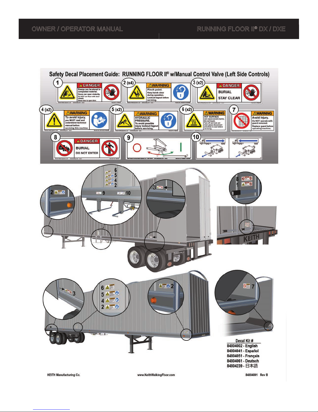
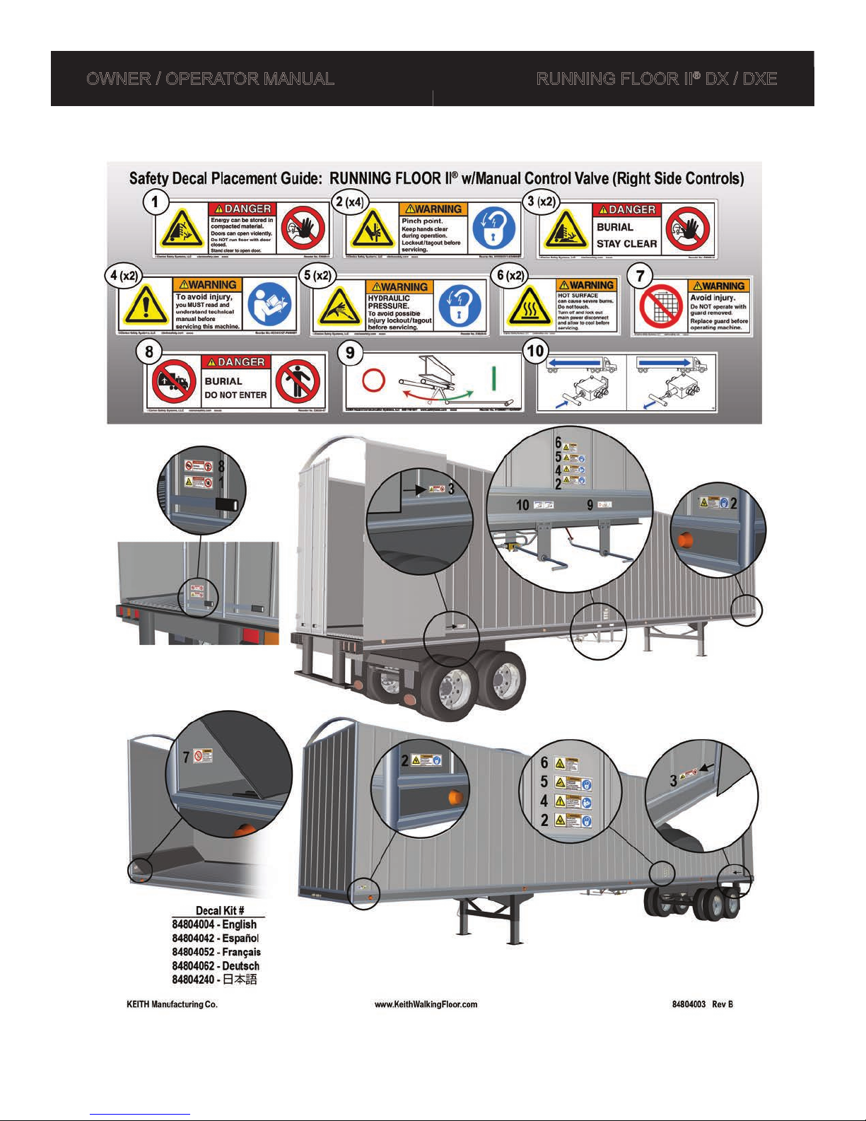
1.3 Marking of Machinery
1.3.1 Safety Decals
5 DOC06179 Rev. B
OWNER / OPERATOR MANUAL RUNNING FLOOR II® DX / DXE
6 DOC06179 Rev. B

OWNER / OPERATOR MANUAL RUNNING FLOOR II® DX / DXE
7 DOC06179 Rev. B

OWNER / OPERATOR MANUAL RUNNING FLOOR II® DX / DXE
8 DOC06179 Rev. B

OWNER / OPERATOR MANUAL RUNNING FLOOR II® DX / DXE
1.3.2 Serial Plates
Please ll in the information from the serial plate attached to your drive system. Overtime these
plates become difcult to read or even locate and this information is crucial in determining the specic
replacement parts for your system.
9 DOC06179 Rev. B

OWNER / OPERATOR MANUAL RUNNING FLOOR II® DX / DXE
2.0 Specications
2.1 Hydraulic Drive Unit
Drive Style: KRFII-3 KRFII-3.5 KRFII-4
Cylinder Bore Diameter:
Cylinder Stroke:
Relief Valve
Pressure Range:
Min:
Max:
Load Capacity:
Pump Flow Rate:
Recommended Pump Flow
Rate:
* Floor Speed:
Max Temperature:
** Drive Weight:
3.0 in
[76 mm]
6.0 - 10.0 in
[152 - 254 mm]
2,800 PSI [193 bar]
3,000 PSI [207 bar]
35 tons
[31.75 tonnes]
5 - 60 gal/min
[19 - 227 liters/min]
40 - 45 gal/min
[151 - 170 liters/min]
1 - 16.5 ft/min
[0.3 - 5 meters/min]
140 °F
[60 °C]
850 - 1700 lbs
[386 - 771 kg]
3.5 in
[89 mm]
6.0 - 10.0 in
[152 - 254 mm]
2,800 PSI [193 bar]
3,000 PSI [207 bar]
50 tons
[45.5 tonnes]
5 - 60 gal/min
[19 - 227 liters/min]
40 - 45 gal/min
[151 - 170 liters/min]
1 - 11.5 ft/min
[0.3 - 3.5 meters/min]
140 °F
[60 °C]
950 - 1825 lbs
[431 - 828 kg]
4 in
[102 mm]
6.0 in
[152 mm]
2,800 PSI [193 bar]
3,000 PSI [207 bar]
75 tons
[68 tonnes]
5 - 60 gal/min
[19 - 227 liters/min]
40 - 45 gal/min
[151 - 170 liters/min]
1 - 8.5 ft/min
[0.3 - 2.6 meters/min]
140 °F
[60 °C]
1500 - 2100 lbs
[680 - 953 kg]
* Floor Speed (Load/Unload times) vary with pump ow rate, length of trailer, material type or other
environmental variables.
** Varies by drive conguration and application.
10 DOC06179 Rev. B

OWNER / OPERATOR MANUAL RUNNING FLOOR II® DX / DXE
2.2 General Wet Kit Specications
Oil: ISO-L-HM 46 hydraulic oil (As per ISO 11158).
The PTO and Pump must be capable of producing a minimum ow rate of 5
gal/min at 3000 PSI [19 liters/min at 207 bar] for proper operation. KEITH
recommends a PTO and Pump capable of producing between 40 and 60 gal/min at
less than 3000 PSI [151-227 liters/min at less than 207 bar] for optimal operation.
NOTE: Pumps with built-in pressure relief valves are NOT recommended.
PTO and
Pump: *
Filter:
Hydraulic
Reservoir:
Suction Line:
Pressure Line:
®
See the Wet Kit RUNNING FLOOR II
document available on the KEITH website
www.KeithWalkingFloor.com or contact a KEITH Manufacturing Co. representative
for specic recommendations on selecting a wet kit.
Do not exceed the maximum ow rate.
Do not exceed the maximum pressure.
Filter should be double element, 10 to 25 µm, on the return line.
(The lter element should be changed after the initial 6 hours of operation, then
every 6 months thereafter. This may vary with the operating environment).
Sized to desired ow rate. Should hold approximately 1 gallon of oil for every gallon
per minute you plan to pump, i.e. 40 gal/min = 40 gallon reservoir. Minimum 40
gallons [151 liters]
Suction hose from the reservoir tank to the pump should be no more than 5 ft [1.5 m]
in length and a minimum of 2 inch [51 mm] inside diameter.
KEITH recommends using SAE100R4 (This type of hose has a spiral wire to keep
the hose from collapsing under suction).
Hose from wet kit to oor should be 1 in [-16] SAE-100R2.
Return Line:
Pressure
Relief Valve: *
Hose from oor to wet kit lter should be 1 in [-16] SAE-100R1.
Hose from lter to reservoir tank should be 1¼ in [-20] SAE-100R1.
High quality valve with the ability to relieve full pump ow at 3000 PSI [207 bar].
NOTE: Relief valve must be set above 2800 PSI [193 bar] and no higher than 3000
PSI [207 bar]
* If the information about your pump and pressure relief valve is not known, have a pressure/ow
check done by a professional.
11 DOC06179 Rev. B

OWNER / OPERATOR MANUAL RUNNING FLOOR II® DX / DXE
2.3 Floor to Wet Kit Connection Diagram
IMPORTANT
To ensure proper operation of your KEITH
®
WALKING FLOOR
®
, the
specifications and following diagram must be followed. Failure to
Reservoir
Tank
®
Warranty.
Pressure
Relief
Valve
Pump
Sight
Gauge
2" Suction
Hose
P.T.O.
RES
CYL
PUMP
CYL
RES
Switching
Valve
RES
CYL
PUMP
CYL
RES
Ball
Valve
comply with these instructions may void the KEITH
Return
1" Female
Quick Coupler
1" Male
Quick Coupler
Suction
Pressure
1" Male
Quick Coupler
RETURN FLOW
PRESSURE FLOW
1" Female
Quick Coupler
1" Return
Hose
1-1/4" Return
Filters
1" Pressure
Relief Hose
Internal
Baffle
Hose
FLOOR
WET KIT
1" Pressure
Hose
46093
12 DOC06179 Rev. B

OWNER / OPERATOR MANUAL RUNNING FLOOR II® DX / DXE
3.0 Operation
3.1 How It Works
Initial Stage
All slats are staged together toward the direction of
material travel (discharge end).
Stage 1
The rst group of slats (approximately every 3rd slat)
moves under the load.
Load does not move.
Stage 2
The second group of slats moves under the load.
Load does not move.
Stage 3
The nal group of slats moves under the load.
Load does not move.
Stage 4
All slats move together.
13 DOC06179 Rev. B
Load moves with the oor toward the discharge end.
(Stages 1, 2 & 3 require more pressure than Stage 4.)

OWNER / OPERATOR MANUAL RUNNING FLOOR II® DX / DXE
3.2 Oil Flow Diagrams
14 DOC06179 Rev. B

OWNER / OPERATOR MANUAL RUNNING FLOOR II® DX / DXE
15 DOC06179 Rev. B

OWNER / OPERATOR MANUAL RUNNING FLOOR II® DX / DXE
Component Location Guide
RUNNING FLOOR II
® DX
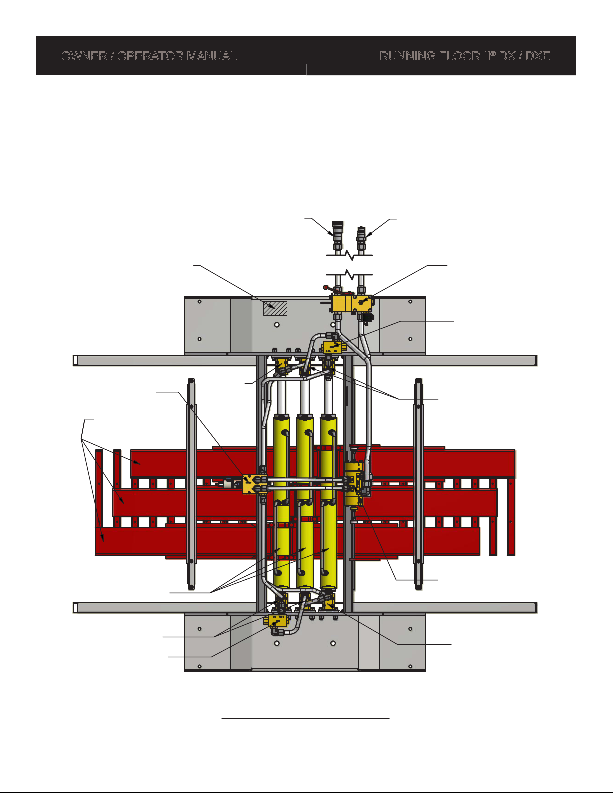
3.3 Component Location Guides
Manual Controls (Left Side),
Restrictor Valves (If Required)
)
r
e
l
i
a
r
T
f
o
e
d
i
S
t
h
g
i
R
(
Serial Numbers are
located underneath
front stiffener plate.
Cross-Drives
Check Valves
#1
#2
#3
Adapter
Block
(Front of Trailer)
Return
1
2
3
Pressure
Ball Valve
(Manual)
BV Handle
On ─►
◄─ Off
CV Handle
Unload ─►
◄─ Load
Control
Valve
(Manual)
Switching
Valve
(
L
e
f
t
S
i
d
e
o
f
T
r
a
i
l
e
r
)
Cylinders
Check Valves
16 DOC06179 Rev. B
Restrictor
Valves
Adapter Block
(Rear of Trailer)
View From Underneath Trailer
97010-1

OWNER / OPERATOR MANUAL RUNNING FLOOR II® DX / DXE
Component Location Guide
RUNNING FLOOR II® DXE
Manual Controls (Right Side),
Restrictor Valves (If Required)
(Front of Trailer)
BV Handle
◄─ On
Off ─►
CV Handle
◄─ Load
Unload ─►
Return
Serial Numbers are
located underneath
front stiffener plate.
Pressure
Ball Valve
(Manual)
Cross-Drives
)
r
e
l
i
a
r
T
f
o
e
d
i
S
t
h
g
i
R
(
Check Valves
Check Valves
#1
#2
#3
Cylinders
Adapter
Block
3
2
1
Control Valve
(Manual)
Switching Valve
Restrictor Valves
Adapter Block
(
L
e
f
t
S
i
d
e
o
f
T
r
a
i
l
e
r
)
(Rear of Trailer)
View From Underneath Trailer
17
97010-4
DOC06179 Rev. B
OWNER / OPERATOR MANUAL RUNNING FLOOR II® DX / DXE
Component Location Guide
RUNNING FLOOR II® DXE
Electric Controls,
Restrictor Valves (If Required)
Serial Numbers are
located underneath
front stiffener plate.
Control Valve
(Electric)
Cross-Drives
)
r
e
l
i
a
r
T
f
o
e
d
i
S
t
h
g
i
R
(
#2
#3
#1
Adapter
Block
(Front of Trailer)
Return
1
2
3
Pressure
Ball Valve
(Electric)
Restrictor
Valve
Check Valves
(
L
e
f
t
S
i
d
e
o
f
T
r
a
i
l
e
r
)
Cylinders
Check Valves
Restrictor Valve
Switching Valve
Adapter Block
(Rear of Trailer)
View From Underneath Trailer
97010-6
18 DOC06179 Rev. B

OWNER / OPERATOR MANUAL RUNNING FLOOR II® DX / DXE
3.4 Drive Component Identication
(See RUNNING FLOOR II® DX or DXE Parts Catalogs for additional details)
19 DOC06179 Rev. B

OWNER / OPERATOR MANUAL RUNNING FLOOR II® DX / DXE
3.5 Start-Up Operation
3.5.1 Before initial start-up:
• Read through this manual. If there is any confusion, contact a KEITH representative and resolve
any concerns before operation of this system (see Contact Information section).
• Ensure that the hydraulic reservoir has the recommended amount of oil as well as the correct type
of oil (see Specications section or visit our website for additional details).
• Torque cylinder barrel clamp bolts and oor bolts. Floor bolts coming loose can severely damage
oor slats. (See Maintenance section)
• Familiarize yourself with the Preventative Maintenance section of this manual. Following the
maintenance schedule will signicantly improve the life of the system.
3.5.2 After initial 6 working hours OR rst week of operation:
• Visually inspect the system for hydraulic leaks. If any leaks are found, retighten ttings.
• Change oil lters. This will ensure that any contamination that was ushed out in the start-up will
not prematurely wear out your system.
• Torque cylinder barrel clamp bolts and oor bolts. Loose oor bolts can severely damage oor
slats. If any bolts were loose, bolt torques will need to be checked twice as often as recommended
in the Maintenance section of this manual.
3.6 Pre-Trip Checklist
9 Inspect hoses and quick connectors for damage and contamination. Clean all dirt and water from
connectors before hooking up (if applicable).
9 Inspect drive unit for leaking ttings or hoses, and visible damage.
9 Open truck or trailer doors and inspect ooring for damage. Inspect ooring at the rear of the truck
or trailer for loose or bent slats that may have popped up.
9 Hook up hydraulic connectors if applicable and operate the oor. Inspect for leaks while operating.
Test the remote control or engage and disengage ball valve fully to check for proper operation (On/
Off). Check control valve for proper operation (Load/Unload).,
9 If problems are found, report them to the maintenance shop as soon as possible.
9 Secure truck or trailer doors and proceed.
As the driver, you will see damage or operational problems before anyone else. Please report issues and
concerns as soon as possible.
Do not attempt to make adjustments or repairs without consulting with a trained service technician from
your company or KEITH Manufacturing Co. (See the Technical Support section for contact information.)
20 DOC06179 Rev. B

OWNER / OPERATOR MANUAL RUNNING FLOOR II® DX / DXE
3.7 Manual Controls
1. Set parking brake on truck and trailer.
2. Open truck or trailer doors fully and secure doors with provided chains or loop rings.
⚠ CAUTION: ALWAYS have doors fully open! Do not, under any circumstances, engage the Power
Take Off (PTO) / Pump System or
closed. Catastrophic failure to the trailer, as well as serious injury or death may occur.
3. Inspect hydraulic hoses and quick connects for damage, then connect the oor to the truck wet
kit (If applicable).
4. Engage the PTO, then bring the truck engine up to the RPM to achieve desired ow rate from
the wet kit.
5. Place control valve (See gure below) in the required position for the desired direction of
material movement (Unload/Load).
WALKING FLOOR
® unloader with the doors of the truck or trailer
6. Pull the ball valve (See gure above) fully closed. It is located between the pressure and return
lines. Your truck or trailer oor should now be operating. NOTE: This ball valve controls (On/Off)
and is used as an emergency shut-off.
⚠ CAUTION: While unloading, NEVER leave truck and trailer unattended.
⚠ WARNING: Do not go under the truck or trailer body or enter the truck or trailer while the
system is in operation, nor allow anyone to stand or move through the area where the load is being
discharged. Burial, loss of limb or life may occur.
7. After loading/unloading has been completed, stop the oor with all slats in the forward position
by pushing the ball valve to the fully open position.
8. Disengage PTO and return the truck engine to idle.
9. Close and secure the truck or trailer doors.
10. Disconnect and secure the hydraulic hoses (If applicable).
EMERGENCY STOP:
• Disengage the PTO / Pumping System.
• Push the ball valve fully open.
In case of emergency the oor can be stopped in one of the following ways:
⚠ CAUTION: Observations may be made while system is operating for troubleshooting purposes,
but NEVER touch any moving part or attempt to make any adjustments to the system with the Power
Take Off (PTO) / Pumping System engaged or the
WALKING FLOOR
® unloader operating.
21 DOC06179 Rev. B

OWNER / OPERATOR MANUAL RUNNING FLOOR II® DX / DXE
3.8 Electric On/Off, Manual Load/Unload - Wireless Remote Control
3.8.1 4 Channel Remote Control Transmitter
EMS - Emergency STOP
Status Indicator LED
Power ON Key
B
D
A (ON)
C
ID Plate
1. Before operating, follow the Pre-Trip Check List.
2. Open truck or trailer doors fully and secure doors with provided chains or loop rings.
⚠ CAUTION: ALWAYS have doors fully open! Do not, under any circumstances, engage the Power
Take Off (PTO) / Pump System or
closed. Catastrophic failure to the trailer, as well as serious injury or death may occur.
3. Inspect hydraulic hoses and quick connects for damage, then connect the oor to the truck wet
kit (If applicable).
4. Engage the PTO, then bring the truck engine up to the RPM to achieve desired ow rate from the
wet kit.
5. Turn ON the remote receiver by twisting the EMS button clockwise to disengage the EMS
(emergency stop) button. (The button will pop up.)
22 DOC06179 Rev. B
WALKING FLOOR
® unloader with the doors of the truck or trailer

OWNER / OPERATOR MANUAL RUNNING FLOOR II® DX / DXE
6. Insert the yellow power-on key into the transmitter. The status indicator LED will start blinking.
Transmitter Status Indicator:
Green
Red: Battery power low. Requires 4x AA (1.5V) alkaline or nickel rechargeable batteries.
7. The remote transmitter is now ready for use.
: Battery power sufcient
ON - Continuous:
will continue to move until the “ON” button is pressed again.
“B” - Momentary:
continue to move until the button is released.
Push and release the “ON” button on the remote transmitter. The oor
Push and hold the “B” button on the remote transmitter. The oor will
⚠ CAUTION: While unloading, NEVER leave truck and trailer unattended.
⚠ WARNING: Do not go under the truck or trailer body or enter the truck or trailer while the
system is in operation, nor allow anyone to stand or move through the area where the load is being
discharged. Burial, loss of limb or life may occur.
8. After unloading has been completed, stop the oor with all slats in the forward position, turn off
the remote control by pushing the EMS button and remove the power-on key from the transmitter.
9. Turn off the receiver by pushing the EMS button.
10. Disengage PTO and return the truck engine to idle.
11. Close and secure the truck or trailer doors.
12. Disconnect and secure the hydraulic hoses (If applicable).
EMERGENCY STOP:
• Push the red EMS (emergency stop) button on the transmitter or receiver.
• Remove the yellow key from the transmitter.
• Disengage the PTO / Pumping System.
• Cut the electric power to the receiver.
In case of emergency the oor can be stopped in one of the following ways:
IMPORTANT NOTE: The KEITH wireless remote control has some built in features:
• The oor automatically stops moving if the continuous signal link, between receiver and transmitter,
is not detected.
• The wireless remote control automatically turns off after 10 minutes of continuous use.
23 DOC06179 Rev. B

OWNER / OPERATOR MANUAL RUNNING FLOOR II® DX / DXE
3.8.2 4 Channel Remote Control Receiver
Function LEDs
Power LED
Operation LED
Data LED
Frequency LED
RECEIVER STATUS INDICATOR:
Power LED
• GREEN = Receiver power is ON
Operation LED
• GREEN = Both transmitter and receiver are ON
• OFF = Transmitter power is OFF
ID Plate
EMS - Emergency STOP
Data LED
• OFF briey = A button on the transmitter was pressed
• RED = Transmitter OFF (EMS engaged and/or Power Key not inserted))
• RED blinking slowly = Normal continuous signal link
• RED blinking irregularly = ID codes don’t match
Frequency LED
• OFF = Normal state
• RED = Blinking irregularly when interference incurred
Function LEDs
• ON = Solid RED light “A” until pressed again or until “B” is pressed
• B = RED “A” and GREEN “B” both light while button is pressed
• C = RED “C” light while button is pressed
• D = GREEN “D” light while button is pressed
24 DOC06179 Rev. B

OWNER / OPERATOR MANUAL RUNNING FLOOR II® DX / DXE
3.9 Electric On/Off & Electric Load/Unload - Wireless Remote Control
3.9.1 4 Channel Remote Control Transmitter
EMS - Emergency STOP
Power ON Key
Status Indicator LED
(Load) B
(Left) D
A (Unload)
C (Right)
ID Plate
1. Before operating, follow the Pre-Trip Check List.
2. Open truck or trailer doors fully and secure doors with provided chains or loop rings.
⚠ CAUTION: ALWAYS have doors fully open! Do not, under any circumstances, engage the Power
Take Off (PTO) / Pump System or
closed. Catastrophic failure to the trailer, as well as serious injury or death may occur.
3. Inspect hydraulic hoses and quick connects for damage, then connect the oor to the truck wet
kit (If applicable).
4. Engage the PTO, then bring the truck engine up to the RPM to achieve desired ow rate from the
wet kit.
5. Turn ON the remote receiver by twisting the EMS button clockwise to disengage the EMS
(emergency stop) button. (The button will pop up.)
25 DOC06179 Rev. B
WALKING FLOOR
® unloader with the doors of the truck or trailer

OWNER / OPERATOR MANUAL RUNNING FLOOR II® DX / DXE
6. Insert the yellow power-on key into the transmitter. The status indicator LED will start blinking.
Transmitter Status Indicator:
Green
Red: Battery power low. Requires 4x AA (1.5V) alkaline or nickel rechargeable batteries.
7. The remote transmitter is now ready for use.
: Battery power sufcient
UNLOAD:
will continue to move until he “UNLOAD” button is pressed again.
LOAD: Push and hold the “LOAD” button. The oor will continue to move until the
button is released.
LEFT / RIGHT: These buttons can be used for other functions, for example retracting a
KEITH Walking Floor Sweep System. Pushing and holding one of these
buttons activates the function until the button is released.
Push and release the “UNLOAD” button on the remote transmitter. The oor
⚠ CAUTION: While unloading, NEVER leave truck and trailer unattended.
⚠ WARNING: Do not go under the truck or trailer body or enter the truck or trailer while the
system is in operation, nor allow anyone to stand or move through the area where the load is being
discharged. Burial, loss of limb or life may occur.
8. After loading/unloading has been completed, stop the oor with all slats in the forward position.
Turn off the remote control by pushing the EMS button and remove the power-on key from the
transmitter.
9. Turn off the receiver by pushing the EMS button.
10. Disengage PTO and return the truck engine to idle.
11. Close and secure the truck or trailer doors.
12. Disconnect and secure the hydraulic hoses (If applicable).
EMERGENCY STOP:
• Push the red EMS (emergency stop) button on the transmitter or receiver.
• Remove the yellow key from the transmitter.
• Disengage the PTO / Pumping System.
• Cut the electric power to the receiver.
IMPORTANT NOTE: The KEITH wireless remote control has some built in features:
• The oor automatically stops moving if the continuous signal link, between receiver and transmitter,
is not detected.
• The wireless remote control automatically turns off after 10 minutes of continuous use.
26 DOC06179 Rev. B
In case of emergency the oor can be stopped in one of the following ways:

OWNER / OPERATOR MANUAL RUNNING FLOOR II® DX / DXE
3.9.2 4 Channel Remote Control Receiver
Function LEDs
Power LED
ID Plate
Operation LED
Data LED
Frequency LED
EMS - Emergency STOP
RECEIVER STATUS INDICATOR:
Power LED
• GREEN = Receiver power is ON
Operation LED
• GREEN = Both transmitter and receiver are ON
• OFF = Transmitter power is OFF
Data LED
• OFF briey = A button on the transmitter was pressed
• RED = Transmitter OFF (EMS engaged and/or Power Key not inserted))
• RED blinking slowly = Normal continuous signal link
• RED blinking irregularly = ID codes don’t match
Frequency LED
• OFF = Normal state
• RED = Blinking irregularly when interference incurred
Function LEDs
• UNLOAD = Solid RED light “A” until any button is pressed
• LOAD = RED “A” and GREEN “B” both light while button is pressed
• RIGHT = RED “C” light while button is pressed
• LEFT = GREEN “D” light while button is pressed
27 DOC06179 Rev. B

OWNER / OPERATOR MANUAL RUNNING FLOOR II® DX / DXE
3.10 Electric On/Off & Electric Load/Unload - Cabled Remote Control
1. Before operating, follow the Pre-Trip Check List.
2. Open truck or trailer doors fully and secure doors with
provided chains or loop rings.
Emergency
STOP Button
⚠ CAUTION: ALWAYS have doors fully open! Do not, under any
circumstances, engage the Power Take Off (PTO) / Pump System or
WALKING FLOOR
closed. Catastrophic failure to the trailer, as well as serious injury
or death may occur.
3. Inspect hydraulic hoses and quick connects for damage,
then connect the oor to the truck wet kit (If applicable).
4. Engage the PTO, then bring the truck engine up to the
RPM to achieve desired ow rate from the wet kit.
5. Turn on the electric power to operate the remote control.
6. Turn ON the remote by twisting the EMS button clockwise
to disengage the EMS (emergency stop) button. (The
button will pop up.)
® unloader with the doors of the truck or trailer
UNLOAD Button
LOAD Button
(Push Down)
(EMS)
(Push Up)
7. Now the remote control is ready for use.
UNLOAD:
the Up button is pushed again.
LOAD: Push and hold the Down button. The oor will move until the button is released.
Push and release the Up button on the control. The oor will continue to move until
⚠ CAUTION: While unloading, NEVER leave truck and trailer unattended.
⚠ WARNING: Do not go under the truck or trailer body or enter the truck or trailer while the system is
in operation, nor allow anyone to stand or move through the area where the load is being discharged.
Burial, loss of limb or life may occur.
8. After loading/unloading has been completed, stop the oor with all slats in the forward position,
turn off the remote control by pushing the EMS button.
9. Turn off the electric power to the remote control.
10. Disengage PTO and return the truck engine to idle.
11. Close and secure the truck or trailer doors.
12. Disconnect and secure the hydraulic hoses (If applicable).
EMERGENCY STOP:
• Push the red EMS (emergency stop) button on the remote
• Disengage the PTO / Pumping System.
In case of emergency the oor can be stopped in one of the following ways:
28 DOC06179 Rev. B

OWNER / OPERATOR MANUAL RUNNING FLOOR II® DX / DXE
3.11 Manual Override of Electric Controls
In the case of a malfunction in the electrical system or loss of the remote control, the electric valves can still
be operated by activating the manual override tted for that purpose.
1. Before operating, follow the Pre-Trip Check List.
2. Open truck or trailer doors fully and secure doors with provided chains or loop rings.
⚠ CAUTION: ALWAYS have doors fully open! Do not, under any circumstances, engage the Power
Take Off (PTO) / Pump System or
closed. Catastrophic failure to the trailer, as well as serious injury or death may occur.
3. Inspect hydraulic hoses and quick connects for damage, then connect the oor to the truck wet
kit (If applicable).
4. Engage the PTO, then bring the truck engine up to the RPM to achieve desired ow rate from the
wet kit.
5. Determine if the oor is in the load or unload mode. The typical position of the solenoid is in the
unload position. If the oor is in the loading mode, take off the protective plastic cap. Push the
red button in (1) and turn it a half turn counter clockwise (2). Release the red button and it will
pop out.
WALKING FLOOR
® unloader with the doors of the truck or trailer
1
2
Manual Override - Control Valve (solenoid)
29 DOC06179 Rev. B

OWNER / OPERATOR MANUAL RUNNING FLOOR II® DX / DXE
6. There are two ways to put the Ball Valve (On/Off) of the drive in ON-position
A) Move the red handle to the driver’s side as in image below. (See image below.) The oor will
start to move! Take into account that the system can be left-hand (LH) or right-hand (RH) drive.
Manual Override - Ball Valve (handle)
RH – ON
LH – OFF
B) Push the red button in (1) and turn it a half turn counter clockwise (2). Release the red button
and it will pop out. (See image below.) The oor will start to move!
RH – OFF
LH – ON
1
2
Manual Override - Ball Valve (solenoid)
7. The oor can be stopped by returning the red handle or red button to the original position.
8. After using the system, return the red solenoid buttons to the original position.
30 DOC06179 Rev. B

OWNER / OPERATOR MANUAL RUNNING FLOOR II® DX / DXE
4.0 Maintenance
⚠ WARNING: The extreme forces exerted by the oor, when in operation, can result in damage to
equipment, as well as cause serious injury or death. Always follow lockout/tagout procedures. Switch
off the Power Take Off (PTO) / Pumping System and manually push the ball valve to the fully open
position during maintenance and/or service work.
4.1 Life Extending Conditions
• Follow the Start-Up procedures in the Operation section of this manual.
• Use only clean oil, free from contamination.
• Use required torque on all bolts. The cylinder barrel clamp bolts and the oor bolts attaching the
slats must be checked regularly. Loose oor bolts will cause serious damage to the oor slats. (See
Bolt Torque Requirements section)
4.2 Preventative Maintenance
4.2.1 Monthly Service (25 operating hours)
• Check the system for hydraulic leaks.
• Check the operating temperature. No single component should be warmer than 140 ºF [60 °C] while
the system is running.
• Check and torque all oor bolts attaching the oor slats. (See Bolt Torque Requirements section)
• Check and torque the cylinder barrel clamp bolts. (See Bolt Torque Requirements section)
• Pressure wash drive unit, sub-deck, and slats (recommended quarterly, minimum twice per year).
4.2.2 6-Month Service (150 operating hours)
• Change the oil lters.
• Cycle the system (unloaded) in both directions and observe to ensure proper operation.
• Inspect cross-drive support bearings, wearpads, tubes and shoes for wear. (See Cross-Drive Wear
Component Diagram section). Replace as needed.
• Inspect oor wear bearings and seals for excessive wear (especially above the tires). (See
Floorings Wear Component Diagrams section) Replace as needed.
• Inspect oor slats for wear. If discharge end of slats are worn more than 75% of original thickness
rotate all oor slats, end for end, to increase life of the oor. If oor has already been rotated,
contact KEITH for replacement slats.
31 DOC06179 Rev. B

OWNER / OPERATOR MANUAL RUNNING FLOOR II® DX / DXE
4.3 Bolt Torque Requirements
Description Size Quantity Torque Values
3 in & 3.5 in Cylinder
Barrel Clamp Bolts
4 in Cylinder Barrel Clamp Bolts
(require Loctite 243 PN#24079)
Cylinder Rod End Bolts
Check Valve & Adapter Block Bolts
Floor Bolts (Flat Head)
Floor Bolts (Flat Head)
5/8 in HCS
[16 mm] HCS
3/4 in HCS
[20 mm] HCS
5/8 in HCS
[16 mm] HCS
5/16 in HCS
[8 mm] HCS
5/16 in FHCS (82°)
[8 mm] FHCS (90°)
3/8 in FHCS (82°)
[10 mm] FHCS (90°)
4 per cylinder
4 per cylinder
8 per cylinder
4 per valve or block
Varies with Flooring
Varies with Flooring
135 ft-lbs
[183 N·m]
125 ft-lbs
[170 N·m]
135 ft-lbs
[183 N·m]
20 ft-lbs
[27 N·m]
24 ft-lbs
[32 N·m]
45 ft-lbs
[61 N·m]
32 DOC06179 Rev. B

OWNER / OPERATOR MANUAL RUNNING FLOOR II® DX / DXE
4.4 Cross-Drive Wear Component Diagram
33 DOC06179 Rev. B

OWNER / OPERATOR MANUAL RUNNING FLOOR II® DX / DXE
4.5 Flooring Wear Component Diagrams
34 DOC06179 Rev. B

OWNER / OPERATOR MANUAL RUNNING FLOOR II® DX / DXE
5.0 Troubleshooting
5.1 Check List
Before contacting KEITH Manufacturing Co. for technical assistance please verify the following:
9 Wet Kit: Does your entire wet kit system meet the requirements in the Specications section in this
manual? (Additional Wet Kit information is available on our website.)
9 Plumbing: Is your entire system plumbed per the Floor to Wet Kit Connection Diagram in
Specications section in this manual?
9 Connections: Inspect the quick connects on the hydraulic lines for damage or contamination. Are
the pressure line and return line quick disconnects the correct size and style and are they securely
attached between the wet kit and oor and are they connected Pressure to Pressure, Return to
Return?
9 Pump: Will it pump a minimum of 5 gal/min [19 liters/min] at 3000 PSI [207 bar]?
9 Relief Valve: Is it set between 2800-3000 PSI [193 - 207 bar]?
9 Oil: Is the oil reservoir full?
9 Power Take Off: Is the PTO engaged?
9 Ball Valve: Is the ball valve, that engages the drive unit (On/Off), pulled fully closed?
9 Control Valve: Is the control valve fully engaged in the appropriate position (Load/Unload)?
9 Electrical Operation: Is there sufcient voltage? Is the Emergency Stop button disengaged?
5.2 Problem / Solution - Troubleshooting
See Troubleshooting on our website www.KeithWalkingFloor.com
5.3 Adjustments & Repairs
See Support and Troubleshooting on our website www.KeithWalkingFloor.com
5.4 Technical Support
Please have the following information readily available before contacting KEITH Manufacturing Co. for
support:
• Model Number (Located on the Serial Plate of the drive unit)
• Serial Number (Located on the Serial Plate on the drive unit)
• Number of oor slats
• Vehicle make and unit installer
KEITH Manufacturing Co. Technical Support Contact Information:
Website: www.KeithWalkingFloor.com
Email: TechDept@KeithWalkingFloor.com
Toll-Free: (800) 547-6161
Telephone: (541) 475-3802
Fax: (541) 475-2169
35 DOC06179 Rev. B

OWNER / OPERATOR MANUAL RUNNING FLOOR II® DX / DXE
6.0 Contact Information
KEITH Manufacturing Co.
World Headquarters
Parts & Service
401 NW Adler St.
P.O. Box 1
Madras, OR 97741
Toll-Free: 800-547-6161
Phone: 541-475-3802
Fax: 541-475-2169
Email: Sales@KeithWalkingFloor.com
Canada
Brantford, ON
Phone: 519-756-9178
Email: CanadaSales@KeithWalkingFloor.com
México
Guadalajara, Jal.
Phone: 52-333-616-5079
Email: KMC_Mexico@KeithWalkingFloor.com
Australia
Waverley Gardens, VIC
Phone: 61-3-9562-2190
Email: AUSales@KeithWalkingFloor .com
Europe
Barneveld, The Netherlands
Phone: 31-342-422007
Email: EuroSales@KeithWalkingFloor.com
36 DOC06179 Rev. B
(Final Page)
 Loading...