

Page 1

SAB 80C517/80C537 Microcontroller Target Board
with 81C90 Full CAN Controller and Banking Support
User’s Guide 04.97
Page 2

ii Keil Software
Information in this document is subject to change without notice and does not
represent a commitment on the part of the manufacturer. The software described
in this document is furnished under license agreement or nondisclosure
agreement and may be used or copied only in accordance with the terms of the
agreement. It is against the law to copy the software on any medium except as
specifically allowed in the license or nondisclosure agreement. The purchaser
may make one copy of the software for backup purposes. No part of this manual
may be reproduced or transmitted in any form or by any means, electronic or
mechanical, including photocopying, recording, or information storage and
retrieval systems, for any purpose other than for the purchaser’s personal use,
without written permission.
© Copyright 1997, 1997 Keil Elektronik GmbH and Keil Software, Inc.
All rights reserved.
Keil C51™ and dScope™ are trademarks of Keil Elektronik GmbH.
®
Microsoft
, MS-DOS®, and Windows™ are trademarks or registered trademarks
of Microsoft Corporation.
®
, PC®, and PS/2® are registered trademarks of International Business
IBM
Machines Corporation.
®
, MCS® 51, ASM-51®, and PL/M-51® are registered trademarks of Intel
Intel
Corporation.
Every effort was made to ensure accuracy in this manual and to give appropriate
credit to persons, companies, and trademarks referenced herein.
A35 D05/06/97
Page 3

MCB517AC Evaluation Board User’s Guide iii
Preface
This manual describes the Keil Software MCB517AC Evaluation Board and the
8051 microcontroller software development tools. The following chapters are
included:
“Chapter 1. Introduction” gives an overview of this user’s guide and provides a
quick start table.
“Chapter 2. Setup” describes how to connect and configure the board and
provides detailed information about the DIP switches and configuration jumpers.
“Chapter 3. Hardware” provides detailed information about hardware including
the schematic drawings for the MCB517AC board, the logic equations for the
PLD and the memory locations of the different Monitor versions contained in the
EPROM.
“Chapter 4. Programming” gives details about how to use our tools to generate
programs for the MCB517AC evaluation board.
“ Chapter 5. Using the 8051 Monitor” gives a quick overview about the MON51
terminal program.
NOTE
This manual assumes that you are familiar with Microsoft Windows and the
hardware and instruction set of the 8051 and 80C517A microcontrollers.
Page 4

iv Preface
Document Conventions
This document uses the following conventions:
Examples Description
README.TXT
Courier
Variables
Elements that
repeat…
Omitted code
.
.
.
Optional Items
Bold capital text is used for the names of executable programs, data files,
source files, environment variables, and commands you enter at the
MS-DOS command prompt. This text usually represents commands that
you must type in literally. For example:
CLS DIR L51.EXE
Note that you are not required to enter these commands using all capital
letters.
Text in this typeface is used to represent information that displays on
screen or prints at the printer.
This typeface is also used within the text when discussing or describing
command line items.
Text in italics represents information that you must provide. For example,
projectfile
file name.
Occasionally, italics are also used to emphasize words in the text.
Ellipses (…) are used to indicate an item that may be repeated.
Vertical ellipses are used in source code listings to indicate that a fragment
of the program is omitted. For example:
in a syntax string means that you must supply the actual project
void main (void) {
.
.
.
while (1);
Optional arguments in command-line and option fields are indicated by
double brackets. For example:
C51 TEST.C PRINT (
{
opt1
|
opt2
} Text contained within braces, separated by a vertical bar represents a
group of items from which one must be chosen. The braces enclose all of
the choices and the vertical bars separate the choices. One item in the list
must be selected.
Keys
Text in this sans serif typeface represents actual keys on the keyboard.
For example, “Press Enter to continue.”
filename
)
Page 5

MCB517AC Evaluation Board User’s Guide v
Contents
Chapter 1. Introduction..................................................................................... 1
Quick Start.....................................................................................................................2
Chapter 2. Setup................................................................................................. 3
Using the MCB517AC..................................................................................................4
Configuring the MCB517AC........................................................................................5
DIP Switches.................................................................................................................6
Configuration Jumper....................................................................................................9
Monitor Modes..............................................................................................................9
Monitor Status Display................................................................................................10
Chapter 3. Hardware....................................................................................... 11
Schematics...................................................................................................................17
Printed Board Assembly..............................................................................................21
Technical Data.............................................................................................................22
PAL Equations ............................................................................................................22
Monitor EPROM Addresses........................................................................................27
Chapter 4. Programming................................................................................. 29
Monitor Memory Map.................................................................................................29
Monitor Data & Interrupt Vectors...............................................................................31
Writing Programs for the 8051 Monitor......................................................................32
BLINKY Example Program........................................................................................33
External CAN Example...............................................................................................43
Code Banking Example...............................................................................................45
Chapter 5. Using the 8051 Monitor ................................................................ 50
MON51 Terminal Program.........................................................................................50
Index................................................................................................................... 54
Page 6

vi Contents
Page 7

MCB517AC Evaluation Board User’s Guide 1
Chapter 1. Introduction
Thank you for letting Keil Software provide you with the MCB517AC
evaluation board and software for the 8051 microcontroller family. With this kit
you can generate code and then operate it on the MCB517AC evaluation board.
This hands-on process helps you determine hardware and software needs for
current and future product development.
The MCB517AC evaluation board lets you become familiar with the different
operating modes of the SAB 80C517 or 80C517A microcontroller and the SAE
81C90 full CAN controller. Alternatively, you may choose just to play with the
board, make it flash the LEDs, and write “Hello World” out the serial port.
This user’s guide describes the hardware of the MCB517AC evaluation board
and contains the operating instructions for the monitor program (Monitor 51) and
the terminal program (MON51.EXE). Both the Monitor 51 with and without
banking support are installed in the EPROM of the MCB517AC board in
different configurations. These monitor programs let you communicate between
your PC and the MCB517AC evaluation board so that you can download and run
your 8051 programs.
The MCB517AC kit includes the following items:
n MCB517AC Evaluation Board User’s Guide (this manual),
n MCB517AC Evaluation Board,
n 9-pin Serial Cable,
n and a 8051 Evaluation Kit which includes a 2K compiler and the MCB517AC
Evaluation Board Software.
Page 8

2 Chapter 1. Introduction
Quick Start
Use the following list to quickly locate important information about the
MCB517AC evaluation board.
To… See…
Connect power to the MCB517AC board. “Using the MCB517AC” on page 4.
Connect the MCB517AC to your PC. “Using the MCB517AC” on page 4.
Read about the default configuration settings. “Configuring the MCB517AC” on page 5.
Create a simple program to blink the LEDs. “BLINKY Example Program” on page 33.
Accessing the external CAN controller. “External CAN Example” on page 43.
Create a simple banked program. “Code Banking Example” on page 45.
Learn more about the µVision IDE. “Using µVision to Create the BLINKY Program”
on page 34.
Learn more about the dScope debugger. “Using dScope to Debug the BLINKY Program”
on page 39.
Learn about the MON51 terminal program. “Chapter 5. Using the 8051 Monitor” on page 50.
Read about the DIP switch settings. “DIP Switches” on page 6.
Read about the configuration jumpers. “Configuration Jumper” on page 9.
Configure the RAM/ROM memory. “Monitor Memory Map” on page 29.
See the MCB517AC schematics. “Schematics” on page 17.
See the MCB517AC PAL equations. “PAL Equations” on page 22.
Page 9

MCB517AC Evaluation Board User’s Guide 3
Chapter 2. Setup
Setting up the MCB517AC evaluation board is easy. The board requires power
and a serial connection to a PC running the MON51 terminal program or dScope
for Windows. Before you start, make sure you have satisfied the following
hardware and software requirements.
Hardware Requirements
n The MCB517AC Evaluation Board.
n A serial cable, 9-pin male to 9-pin female, 1-2 meters long, wired one-to-one.
n A power supply capable of providing 9-12VDC at 300-500mA. The power
cable should terminate with a 5.5mm barrel plug with a 2.5mm center hole.
Plus must be connected to the center hole.
n A PC with an available RS-232 port. If the port has a 25-pin connector, a
9-pin male to 25-pin female adapter may be required.
n A device programmer is required to program any EPROMs or other
programmable devices.
Software Requirements
n The Keil MON51 terminal program (MON51.EXE) or the Keil dScope for
Windows with the MON51.DLL / MON51B.DLL driver.
n The Keil MON51 software/firmware is already programmed into the EPROM
provided on the MCB517AC board.
n Microsoft Windows version 3.1, 3.11, Windows 95 or Windows NT.
Page 10
4 Chapter 2. Setup
Using the MCB517AC
To use the MCB517AC evaluation board, you must:
n Connect the external serial port jack (COM 0) to an serial port on your PC
using the supplied serial cable.
n Connect power using a standard power supply.
The serial cable lets your PC download program code and debug your target
applications. The power cable provides power to the MCB517AC evaluation
board. The MCB517AC does not get power from the PC via the serial cable.
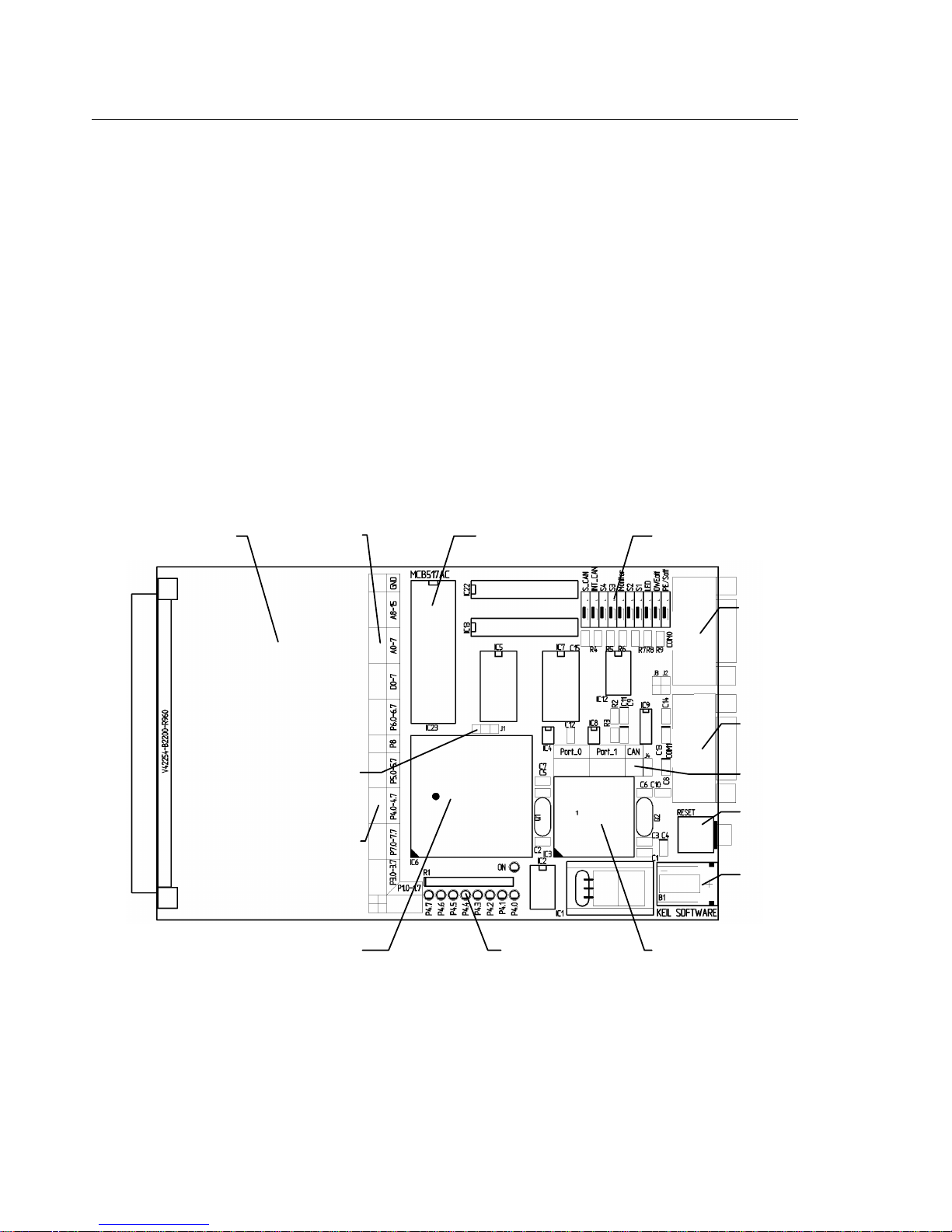
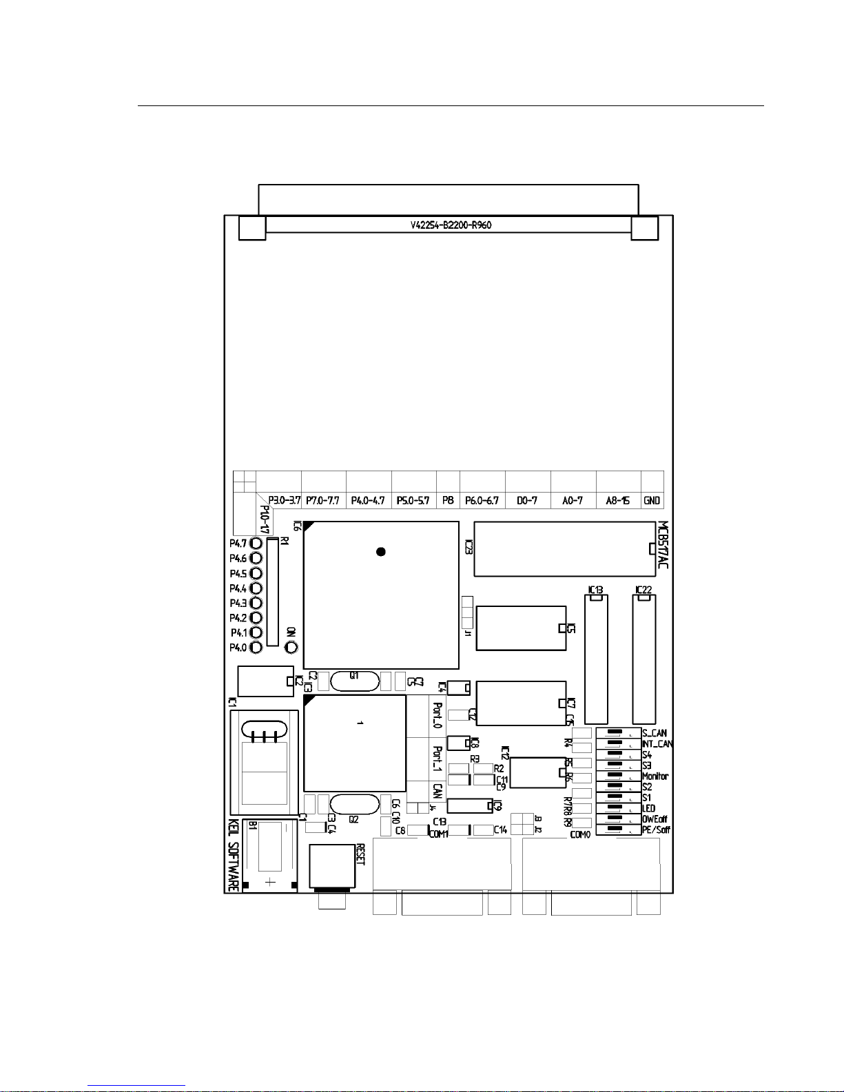
The following illustration shows MCB517AC board and the important interface
and hardware components.
Prototyping
Area
or 80C517A / 83C517A
Bus
Signals
Configuration
Jumper
Port
Signals
80C517 / 80C537
Monitor
EPROM
Port 1 Status
LED’s
DIP
Switches
Serial
Interface 0
Serial
Interface 1
CAN
Interface
Reset Button
Power
Supply
80C91 Full CAN
Controller
Page 11
MCB517AC Evaluation Board User’s Guide 5
Configuring the MCB517AC
You configure the MCB517AC evaluation board with the DIP switches and the
configuration jumpers. The MCB517AC evaluation board is shipped with the
following configuration:
n Siemens SAB 83C517A microcontroller
n Monitor uses serial interface 0 (COM0) at 9600 bps
n Banking disabled
The default DIP switch settings are shown in the following table.
Switch S_
CAN
ON X X X X X X
OFF X X X X
INT
CAN
S4 S3 Moni
tor
S2 S1 LED OWE
off
PE/
Soft
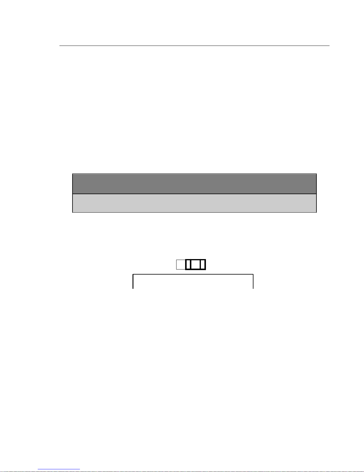
The default setting of the configuration jumper is shown in the following figure.
The jumper is in position 80517A for a 80C517A/83C517A CPU.
80C517A80C517
CPU
Page 12

6 Chapter 2. Setup
DIP Switches
The following sections describe each of the DIP switches of the MCB517AC
board.
S-CAN : Default OFF
The S_CAN switch determines, whether a 120Ohm terminating resistor is
connected to the CAN_H and CAN_L lines. Switch S_CAN only to ON if this
prototype board is connected to one end of a CAN-bus line.
INT_CAN: Default OFF
The INT_CAN switch selects whether or not the external SAE 80C91 full CAN
controller generates an interrupt on the microcontroller. If INT_CAN is ON, the
interrupt output from the 80C91 is connected to port pin 3.2 (\INT0). If
INT_CAN is OFF, the interrupt output from the 80C91 is not connected to the
microcontroller. Switch INT_CAN to ON if you want to use the CAN interface,
or to OFF if INT0 is used for a different interrupt source.
S3: Default ON
S4: Default ON
The S3 and S4 switches select which serial interface and which baudrate is used
by Monitor 51 to communicate with the PC. Therefore these switches are only
relevant when the Monitor DIP switch is ON. The serial interface settings are
shown in the following table.
Serial Interface Setting for Monitor 51 (Monitor DIP Switch is ON)
S4 S3 ser. Interface Baudrate at 12MHz Baudrate at 16MHz
OFF OFF COM 1 9600 bps 12800 bps
OFF ON COM 1 28800 bps 38400 bps
ON OFF COM 1 38400 bps
ON ON COM 0 9600 bps 12800 bps
Page 13

MCB517AC Evaluation Board User’s Guide 7
Monitor: Default ON
The Monitor switch selects if the Monitor is used for debugging or if the
MCB517AC operates with and user application EPROM at IC23. When
Monitor is ON, a the Monitor Memory Mapping is enabled and you must
operate the MCB517AC board with the supplied Monitor EPROM. When
Monitor is OFF the User Memory Mapping is selected and you may insert an
EPROM with your application.
S1: Default OFF
S2: Default OFF
The S1 and S2 switches select the memory map and banking configuration for
the MCB517AC. The memory map used on the MCB517AC board depends on
the setting of the Monitor DIP switch. The memory maps for both settings are
shown in the following tables.
Monitor Memory Mapping (Monitor DIP Switch is ON)
S0 S1 used Pins von Neumann RAM Monitor EPROM Banking
OFF OFF --- 0000h–E7FFh C:E800h–FFFFh disabled
OFF ON illegal illegal illegal illegal
ON OFF illegal illegal illegal illegal
ON ON P6.5-P6.7 Common: 0000h–7FFFh
Bank 0-5: 8000h-E7FFh
User Memory Mapping (Monitor DIP Switch is OFF)
S0 S1 used Pins RAM EPROM Banking
OFF OFF --- X: 0000h–E7FFh C:0000h–FFFFh disabled
OFF ON P6.5 X: 0000h–E7FFh Common: 0000h–7FFFh
Bank 0-1: 8000h-FFFFh
OFF OFF P6.5-P6.5 X: 0000h–E7FFh Common: 0000h–7FFFh
Bank 0-3: 8000h-FFFFh
ON OFF P6.5-P6.7 X: 0000h–E7FFh Common: 0000h–7FFFh
Bank 0-6: 8000h-FFFFh
C:E800h–FFFFh enabled
enabled
enabled
enabled
The CAN interface is always mapped to the address range X:F700h-F7FFh and
the optional user chip select to X:F600h-F6FFh. The 2Kb on-chip XRAM is
available from X:F800h-FFFFh when the SFR-bit XMAP0 is cleared.
Page 14

8 Chapter 2. Setup
LED: Default ON
The LED switch selects whether or not port 4 is connected to the 8 LEDs in the
upper right portion of the board. When LED is ON, the LEDs on port 4 are
enabled. When LED is OFF, the LEDs are not connected to port 4. If you work
with the Monitor DIP switch ON and LED is OFF, then you select also a
Monitor version which does no longer modify the port 4 lines.
OWEoff : Default ON
The OWEoff switch enables or disables the on chip oscillator watchdog. If
OWEoff is ON, the oscillator watchdog is disabled. If OWEoff is OFF, the
oscillator watchdog supervises the crystal frequency and generates a reset if it is
below 1 MHz.
PE/Soff: Default ON
The PE/Soff switch enables or disables the watchdog timer as well as the power
saving modes. If PE/Soff is ON, the watchdog timer is off by default and the
software is able to enter the power down, idle and slow down mode. If PE/Soff
is OFF the watchdog timer is automatically started and the power saving modes
are blocked. When you are using Monitor 51 this switch has to be in ON
position.
Page 15

MCB517AC Evaluation Board User’s Guide 9
Configuration Jumper
The following sections describes the configuration jumper of the MCB517AC
board.
80C517 / 80C517A: Default 80C517A
This configuration jumper selects whether the MCB517AC board operates with a
80C517 or a 80C517A CPU. It switches the CPU pin 60 from V
pin has to be connected to V
(circuit ground) for an 80C517. For an 80C517A
SS
this pin is a hardware reset and power down input (\HWPD). It has to be
connected to V
(high level) for normal operation.
CC
to VCC. This
SS
Monitor Modes
The MCB517AC board comes with an Monitor EPROM which contains 16
different Monitor configurations. Most of the Monitor configurations are
required to use different serial interfaces and baudrates. The other configurations
determine whether the normal or the banked Monitor should be used and whether
the Monitor should flash the LED’s or not.
DIP Switch Monitor Mode
S3 and S4
S1 and S2
LED ON: display Monitor status on Port 1 LED’s (see below).
Monitor ON: use Monitor program for debugging
Refer to “S3 and S4 DIP Switch“ on page 6 which serial interface is used for
Monitor 51 and at which baudrate.
Refer to “S1 and S2 DIP Switch“ on page 7 if a normal or banked Monitor 51
is used for debugging.
OFF: Monitor status is not displayed and Port 1 is not affected..
OFF: User EPROM as IC23. Refer to “S1 and S2 DIP Switch” on page 7 for
the User EPROM Memory Map.
Page 16

10 Chapter 2. Setup
Monitor Status Display
The Monitor program flashes the Port 4 LED’s during the reset phase. After the
reset phase the LED’s reflect the monitor configuration and signals that the board
is working correctly. The following table lists the LED pattern after reset.
Monitor Version P4.7 P4.6 P4.5 P4.4 P4.3 P4.2 P4.1 P4.0
Monitor 51 using COM 0 ON x ON ON ON ON ON ON
Monitor 51 using COM 1 OFF x ON ON ON ON ON ON
Non-Banked Monitor 51 x ON ON ON ON ON ON ON
Banked Monitor 51 x OFF ON ON ON ON ON ON
After the reset phase, the P4.7 status LED is ON when monitor 51 uses the COM
0 interface to communicate with the PC and is OFF when COM 1 interface is
used. P4.6 shows whether the normal or the banked monitor is selected.
Note
If you want to debug a banked application, you have to use dScope for Windows
with the MON51B.DLL loaded.
Page 17
MCB517AC Evaluation Board User’s Guide 11
Chapter 3. Hardware
The MCB517AC is designed to be a very flexible evaluation board that you can
use to become familiar with an 80C517A microcontroller and an 80C91 full
CAN controller. We have also tried to provide a board that can be expanded to
support your own hardware prototypes.
This chapter describes logical sections of the MCB517AC and also provides a
circuit description. The descriptions here will help you understand how the
MCB517AC board works and how you can easily interface to the various I/O
devices available.
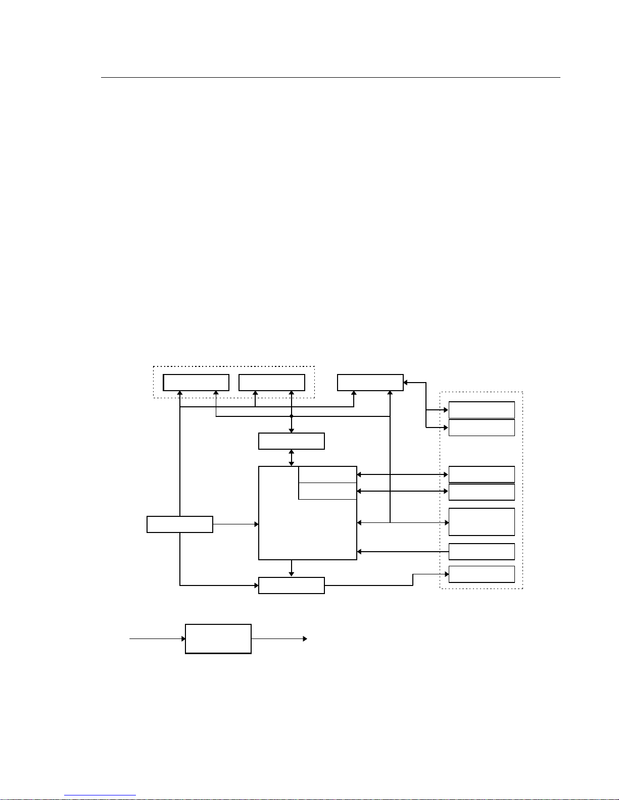
The following block diagram shows the various memory, I/O, configuration, and
power systems that compose the board.
Configuration
Input
8-12V DC
Memory System
RAM EPROM
Buffer
Buffer
Output
Power
Supply
5V +/-5%
serial Port 0
serial Port 1
80C517A
or
80C537
CAN Contr.
User I/O
CAN Line
CAN Ports
RS232
RS232
Bus & Port
Signals
Reset & Int.
P4 LEDs
Page 18

12 Chapter 3. Hardware
Power Supply
Power is supplied to the MCB517AC from an external 8-12 Volt DC power
supply which is capable of providing 300-500mA. Connection is made using a
standard 5.5mm barrel plug with a 2.5mm center hole. The center hole is the
plus polarity. 5 Volts DC is provided to the board by a 7805 voltage regulator at
IC2. To reduce the noise for the 80C517A A/D converter a second 78L05
voltage regulator is provided at IC4.
80C517A/80C517 CPU
The 80C517A provided with the MCB517AC is a 8051 derivative with 2 Kbytes
on-chip XRAM. This part is located at IC6. Alternatively you can insert a
80C517 into the IC6 socket. Please be sure to set the jumper to the correct
position, otherwise the board might be damaged. A 12.000 MHz crystal
provides the clock signal for the CPU.
80C517A80C517
CPU
Configuration
The MCB517AC is a very flexible evaluation board. You can change the
operation of the board using the DIP switches and the configuration jumpers.
Features such as CPU type, LEDs, memory map, memory banking, external
CAN interrupts and different monitor configurations can all be configured using
these switches.
Note
You must RESET the MCB517AC after changing the state of any DIP switch.
Refer to “DIP Switches” on page 6 and “Configuration Jumper” on page 9 for a
complete description of the DIP switches and configuration jumpers.
Page 19

MCB517AC Evaluation Board User’s Guide 13
Decode Logic
All memory address decode logic as well as other signal conversion is performed
by two 20V8 PALs at IC13 and IC22. Refer to “ PAL Equations” on page 22 for
a complete listing of the PAL equations used.
Memory and I/O Devices
The MCB517AC maps three memory devices into the address space of the CPU.
RAM at IC5 and IC7, EPROM at IC23. The two 20V8 PALs at IC13 and IC22
provide also the chip select signal for the external CAN controller at IC3 and an
user chip select signal.
The MCB517AC board comes with an Monitor EPROM at IC23 which contains
up to 16 different Monitor versions. You can use 27C1001 or 27C2001 as an
USER EPROM at IC23. If you insert an EPROM with an user application
program, the DIP switch Monitor must be off. Then you can select different
memory bank options for the user application using the DIP switches S1 and S2.
For more information refer to “DIP Switches” on page 6.
Status LEDs
The MCB517AC has a single power LED labeled ON which indicates the power
to the board is on. Eight LEDs are optionally connected to the port 4 outputs
through a 74HC373 at IC2. The Port 4 LEDs are flashing during reset and
display the configuration status of the Monitor EPROM. For more information
refer to “Monitor Status Display” on page 10. You may disable the LED driver
by setting the LED DIP switch off. In this case you select also a Monitor
version which does not affect the Port 4 Pins during the reset phase.
Push Button
The MCB517AC provides one push button. It is labeled RESET (S1) and
connected to the reset input of the CPU. Pushing this button also resets the
external CAN controller 81C90.
Serial Port
The MCB517AC supports both on-chip serial ports of the 80C517A CPU. Both
of these use the MAX232 at IC9, to convert RS-232 voltage levels.
Page 20

14 Chapter 3. Hardware
You can configure the Monitor to use either the one or the other on-chip serial
port to communicate with the PC. Depending on the position of the DIP
switches S1 and S2 the serial interface and the baudrate is selected for the
Monitor communication. Please refer to “DIP Switches” on page 6 for more
details.
The internal serial port is derived from the internal serial functions of the 80C517
(P3.0/RXD0 and P3.1/TXD0 for COM0 / P6.1/RXD1 and P6.2/TXD1 for
COM1).
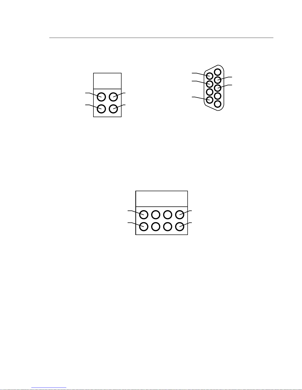
RS232 Connector (DB9F)
5
9
RI
CTS
RTS
DSR
GND
DTR
RxD
TxD
DCD
to MAX232
6
1
Both serial ports are configured as a standard 3-wire interface. The handshaking
signals are connected to loop the PC’s signals back. Refer to the figure above to
determine how the DB9 (female) connector for this port is wired.
CAN Bus
The 81C90 CAN controller transmit and receive lines are connected to a high
speed CAN bus driver PCA82C250 (IC 8). Its slope control (R2 = 120Ohm) is
adjusted for full speed operation with up to 1Mbaud. Typically, the CAN bus is
a shielded twisted wire pair with termination resistors at both ends of the bus
lines. The left figure below shows how to connect these wires to the board.
Since the CAN standard does not include the connectors with which an
application is connected to the CAN bus, it is only recommended to use a 9 pole
male SUB-D connector. The following figure on the right shows how to connect
it.
Page 21
MCB517AC Evaluation Board User’s Guide 15
CAN Connector (DB9M)
1
6
optional GND
CAN_H
optional +5V
9
5
CAN_L
CAN_H
CAN
GND
+5V
CAN Ports
In addition to the CAN receive and transmit lines the 81C90 full CAN controller
has two 8 bit I/O port extensions. Each of these pins can be configured as input
or output depending on the contents of the port-direction register. Refer to the
figure below how these ports are wired.
CAN_L
GND
CAN Port_x
Port_x.6
Port_x.7
Prototyping Area
A perforated area is provided on the MCB517AC for prototyping your own
hardware. All data- and address-bus signals as well as all ports are connected to
the first two rows of the prototyping area. The signals provided are driven
directly by the CPU. Exercise caution to avoid overloading these signal lines.
The following figures show how the ports and bus lines are connected to the
prototype area. Please note that some ports are connected in reverse order.
Port_x.0
Port_x.1
Page 22

16 Chapter 3. Hardware
\PSEN
ALE
P7.0 - P7.7
P1.6
P1.0 - P1.7
P1.7+5V
P7.7P7.1
P4.0 - P4.7
P7.6P7.0
P1.0
P1.1
P3.0 - P3.7
P4.1P4.7
P5.0 - P5.7
P4.0P4.6
P3.1P3.7
P3.0P3.6
P5.1P5.7
P5.0P5.6
P8.3
P8.0 -
P8.3
P8.1
P6.0 - P6.7
P8.0P8.2
A0 - A7
P6.1P6.7
P6.0P6.6
A7A1
A8 - A15
A6A0
DB0 - DB7
A15
GND
A14
DB7DB1
DB6DB0
GND
Page 23

MCB517AC Evaluation Board User’s Guide 17
Schematics
Page 24

18 Chapter 3. Hardware
Page 25

MCB517AC Evaluation Board User’s Guide 19
Page 26

20 Chapter 3. Hardware
Page 27
MCB517AC Evaluation Board User’s Guide 21
Printed Board Assembly
Page 28

22 Chapter 3. Hardware
Technical Data
Supply Voltage: 8V .. 12V DC
Supply Current: typ. 300mA
System Clock: 12 MHz
Memory: 256 KBytes RAM
128 KBytes Monitor EPROM
(optional 256 KBytes User EPROM)
CPU: Siemens 80C517A or 83C517A or 80C517 or 80C537
Peripherals 2 RS232 Interfaces
CAN Interface
PAL Equations
This following lists the PAL equations for the 20V8 logic device at IC13.
;PALASM Design Description
;---------------------------------- Declaration Segment -----------TITLE GAL for MCB517 Prototype board IC13
PATTERN Banking Decoder
REVISION 1.0
AUTHOR Hans Schneebauer
COMPANY Keil Elektonik GmbH
DATE 10/20/96
CHIP IC13 PALCE20V8
;---------------------------------- PIN Declarations --------------PIN 2..4 P6[5..7] COMBINATORIAL ; INPUT
PIN 5 /PSEN COMBINATORIAL ; INPUT
PIN 6 ALE COMBINATORIAL ; INPUT
PIN 8 A15 COMBINATORIAL ; INPUT
PIN 9 /WR COMBINATORIAL ; INPUT
PIN 10 /RD COMBINATORIAL ; INPUT
PIN 11 /LED COMBINATORIAL ; INPUT
PIN 12 GND ; INPUT
PIN 13 /MON_ON COMBINATORIAL ; INPUT
PIN 14 /S[1] COMBINATORIAL ; INPUT
PIN 15..17 A_P[15..17] COMBINATORIAL ; OUTPUT
PIN 18..20 A_R[15..17] COMBINATORIAL ; OUTPUT
PIN 21 /A_R17 COMBINATORIAL ; OUTPUT
PIN 22 C_ACCESS COMBINATORIAL ; OUTPUT
PIN 23 /S[2] COMBINATORIAL ; OUTPUT
PIN 24 VCC ; INPUT
;----------------------------------- Boolean Equation Segment -----EQUATIONS
Page 29

MCB517AC Evaluation Board User’s Guide 23
IF (MON_ON) THEN ; Monitor switched on
BEGIN
A_P[16] = LED
A_P[17] = 0
C_ACCESS = (PSEN * /ALE) + (C_ACCESS * /ALE) ; =1 for a CODE access / =0 for a
XDATA access
CASE(S[2..1])
BEGIN
0: BEGIN ; No Banking
A_P[15] = 0 ; Monitor without banking
A_R[15] = A15
A_R[16] = 0
A_R[17] = 0
A_R17 = 0
END
1: BEGIN ; 64 KB Code + 32KB RAM
A_P[15] = 1 ; Monitor with banking
IF (A15) THEN
BEGIN
A_R[15] = P6[5]
A_R[16] = 0
A_R[17] = 0
A_R17 = 0
END
ELSE
BEGIN
A_R[15] = C_ACCESS + P6[5]
A_R[16] = 1
A_R[17] = 1
A_R17 = 1
END
END
2: BEGIN ; 3 Banks + 32KB RAM
A_P[15] = 1 ; Monitor with banking
IF (A15) THEN
BEGIN
A_R[15..16] = P6[5..6]
A_R[17] = 0
A_R17 = 0
END
ELSE
BEGIN
A_R[15] = C_ACCESS + (P6[5] * P6[6])
A_R[16] = 1
A_R[17] = 1
A_R17 = 1
END
END
3: BEGIN ; 6 Banks + 32 KB Ram
A_P[15] = 1 ; Monitor with banking
IF (A15) THEN
BEGIN
A_R[15..17] = P6[5..7]
A_R17 = P6[7]
END
ELSE
BEGIN
A_R[15] = C_ACCESS + (P6[5] * P6[6] * P6[7])
A_R[16] = 1
A_R[17] = 1
A_R17 = 1
END
END
END
END
ELSE ; Monitor switched off
BEGIN
CASE(S[2..1])
Page 30

24 Chapter 3. Hardware
BEGIN
0: BEGIN ; No Banking
A_P[15] = A15
A_P[16] = 0
A_P[17] = 0
A_R[15] = A15
A_R[16] = 0
A_R[17] = 0
A_R17 = 0
END
1: BEGIN ; 2 Banks with a 1MBit * 8 Eprom
A_P[15] = A15 * /P6[5]
A_P[16] = A15 * P6[5]
A_P[17] = 0
A_R[15] = A15
A_R[16] = 0
A_R[17] = 0
A_R17 = 0
END
2: BEGIN ; 4 Banks with a 2MBit * 8 Eprom
A_P[15] = A15 * /P6[5]
A_P[16] = A15 * P6[5] * /P6[6] +
A15 * /P6[5] * P6[6]
A_P[17] = A15 * P6[5] * P6[6]
A_R[15] = A15
A_R[16] = 0
A_R[17] = 0
A_R17 = 0
END
3: BEGIN ; 7 Banks with a 2MBit * 8 Eprom
A_P[15] = A15 * /P6[5]
A_P[16] = A15 * P6[5] * /P6[6] +
A15 * /P6[5] * P6[6]
A_P[17] = A15 * P6[5] * P6[6] +
A15 * P6[7]
A_R[15] = A15
A_R[16] = 0
A_R[17] = 0
A_R17 = 0
END
END
END
;-------------------------------------------------------------------
This following lists the PAL equations for the 20V8 logic device at IC22.
;PALASM Design Description
;---------------------------------- Declaration Segment -----------TITLE GAL for MCB517 Prototype board IC22
PATTERN Decoder and Boot Logic
REVISION 1.0
AUTHOR Hans Schneebauer
COMPANY Keil Elektonik GmbH
DATE 10/20/96
CHIP IC22 PALCE20V8
;---------------------------------- PIN Declarations --------------PIN 1..8 A[8..15] COMBINATORIAL ; INPUT
PIN 9 /PSEN COMBINATORIAL ; INPUT
PIN 10 /RSTOUT COMBINATORIAL ; INPUT
PIN 11 /RD COMBINATORIAL ; INPUT
PIN 12 GND ; INPUT
Page 31

MCB517AC Evaluation Board User’s Guide 25
PIN 13 /MON_ON COMBINATORIAL ; INPUT
PIN 14 /S[4] COMBINATORIAL ; INPUT
PIN 15 /CS_USER COMBINATORIAL ; OUTPUT
PIN 16 /CS_CAN COMBINATORIAL ; OUTPUT
PIN 17 /CS_RAM COMBINATORIAL ; OUTPUT
PIN 18 /CS_EPROM COMBINATORIAL ; OUTPUT
PIN 19 /RD_RAM COMBINATORIAL ; OUTPUT
PIN 20 MON_RUN COMBINATORIAL ; OUTPUT
PIN 21..22 A_P[13..14] COMBINATORIAL ; OUTPUT
PIN 23 /S[3] COMBINATORIAL ; OUTPUT
PIN 24 VCC ; INPUT
;----------------------------------- Boolean Equation Segment -----EQUATIONS
IF (MON_ON) THEN ; Monitor switched on
BEGIN
RD_RAM = RD + PSEN ; v. Neumann wired RAM
A_P[13..14] = S[3..4]
IF (MON_RUN) THEN
BEGIN
MON_RUN = /RSTOUT
CS_EPROM = (A[15] * A[14] * A[13] * /A[12] * A[11]) + ; e800 - efff
(A[15] * A[14] * A[13] * A[12]) ; f000 - ffff
CS_RAM = /(((A[15] * A[14] * A[13] * /A[12] * A[11]) + ; e800 - efff
(A[15] * A[14] * A[13] * A[12]))) ; f000 - ffff
END
ELSE
BEGIN
CS_EPROM = 1 ; ROM always enabled
CS_RAM = 0 ; RAM always disabled
IF (A[15..8] = #b11101000) THEN ; Address e800 - e8ff
BEGIN
MON_RUN = PSEN * /RSTOUT
END
ELSE
BEGIN
MON_RUN = 0
END
END
END
ELSE ; Monitor switched off
BEGIN
RD_RAM = RD ; Harvard wired RAM
A_P[13..14] = A[13..14]
CS_EPROM = 1
IF (A[15..9] = #b1111011) THEN ; Address f600 - f7ff
BEGIN CS_RAM = 0 END
ELSE
BEGIN CS_RAM = 1 END
END
IF (A[15..8] = #b11110110) THEN ; ADDRESS f600 - f6ff
BEGIN CS_USER = 1 END
ELSE
BEGIN CS_USER = 0 END
IF (A[15..8] = #b11110111) THEN ; ADDRESS f700 - f7ff
BEGIN CS_CAN = 1 END
ELSE
BEGIN CS_CAN = 0 END
;-------------------------------------------------------------------
Page 32

26 Chapter 3. Hardware
Page 33

MCB517AC Evaluation Board User’s Guide 27
Monitor EPROM Addresses
This following lists the EPROM addresses in the Monitor EPROM for the
different monitor versions. At every 8kbyte boundary (address 0, 0x2000,
0x4000 ...) the Monitor EPROM contains a LJMP 0E800H instruction.
Monitor Version EPROM Addresses
Monitor Program
Code
non-banked Monitor, without Flash LED’s 00800H – 01FFFH COM 1 9600 bps
non-banked Monitor, without Flash LED's 02800H – 03FFFH COM1 28800 bps
non-banked Monitor, without Flash LED's 04800H – 05FFFH COM 1 38400 bps
non-banked Monitor, without Flash LED's 06800H – 07FFFH COM0 9600 bps
banked Monitor, without Flash LED's 08800H – 09FFFH COM 1 9600 bps
banked Monitor, without Flash LED's 0A800H – 0BFFFH COM1 28800 bps
banked Monitor, without Flash LED's 0C800H – 0DFFFH COM 1 38400 bps
banked Monitor, without Flash LED's 0E800H – 0FFFFH COM0 9600 bps
non-banked Monitor, with Flash LED's 10800H – 11FFFH COM 1 9600 bps
non-banked Monitor, with Flash LED's 12800H – 13FFFH COM1 28800 bps
non-banked Monitor, with Flash LED's 14800H – 15FFFH COM 1 38400 bps
non-banked Monitor, with Flash LED's 16800H – 17FFFH COM0 9600 bps
banked Monitor, with Flash LED's 18800H – 19FFFH COM 1 9600 bps
banked Monitor, with Flash LED's 1A800H – 1BFFFH COM1 28800 bps
banked Monitor, with Flash LED's 1C800H – 1DFFFH COM 1 38400 bps
banked Monitor, with Flash LED's 1E800H – 1FFFFH COM0 9600 bps
COM bps @
12MHz
Page 34

Page 35

MCB517AC Evaluation Board User’s Guide 29
Chapter 4. Programming
Writing programs for the MCB517AC is relatively simple. However, before you
get started, there are a few points you should keep in mind.
The MCB517AC is shipped with the Keil 51 monitor for banked and non-banked
applications programmed into the EPROM. The MCB517AC board has a
Monitor boot logic which is coded in the PLD device. At Reset the Monitor
EPROM is addressable at address 0. After the execution of the first Monitor
instruction, the Monitor EPROM is addressed at 0xE800 .. 0xFFFF.
If you use the monitor for loading and running programs via the serial port on the
MCB517AC, your programs still start at address 0000h or C:0000. This is the
same address as if you do not use a monitor program.
This chapter describes everything you need to know to write programs for the
MCB517AC evaluation board.
Monitor Memory Map
The MCB517AC evaluation board supports up to 56 KB RAM for non-banked
and 208 KB RAM for banked applications. The memory map depends on the
S0and S1 DIP switches which select the bank mode.
Monitor Memory Mapping (Monitor DIP Switch is ON)
S0 S1 used Pins von Neumann RAM Monitor EPROM Banking
OFF OFF --- 0000h–E7FFh C:E800h–FFFFh disabled
OFF ON illegal illegal illegal illegal
ON OFF illegal illegal illegal illegal
ON ON P6.5-P6.7 Common: 0000h–7FFFh
Bank 0-5: 8000h-E7FFh
The CAN interface is always mapped to the address range X:F700h-F7FFh and
the optional user chip select to X:F600h-F6FFh. The 2Kb on-chip XRAM is
available from X:F800h-FFFFh when the SFR-bit XMAP0 is cleared.
C:E800h–FFFFh enabled
Page 36

30 Chapter 4. Programming
External memory layout in non-banked mode.
Code memory Xdata memory
Monitor EPROM
Mon. Data
User Code Area
(v. Neumann
mapped)
*1
Since this XDATA area is ‘von-Neumann’ wired, write accesses also modify
0FFFFH
On-chip XRAM
CAN-contoller
User Chip select
0E800H
*2
00000H
unused
Mon. Data
User XDATA
(overlaps User
*1
Area
Code Area!)
0FFFFH
*3
0F800H
0F700H
0F600H
0E800H
*2
0D300H0D300H
00000H
the CODE space. Locate your XDATA segments after the end of your
program and constant segments!
*2
Monitor 51 typically requires 256 bytes of external memory (0E700h 0E7FFh). Only when you enable ‘Record trace’ in the dScope ‘Commands’
pull down menu, 5 KB additional memory is required to hold the trace
information.
*3
The 2Kb on-chip XRAM is available only with an 80C517A from X:F800hFFFFh when the SFR-bit XMAP0 is cleared
External memory layout in banked mode.
When the banked memory mode is selected, three port pins (P6.5 - P6.7) are used
to select the current code bank. Although it is possible to access 8 banks with
three additional address lines, your application can only use the first 6 banks with
monitor 51. The other two banks are used to hold the common area and the userXDATA area.
Page 37

MCB517AC Evaluation Board User’s Guide 31
Code memory
Monitor
EPROM
Bank 0
Common
*1
Since this XDATA area is ‘von-Neumann’ wired, write accesses also modify
Monitor
EPROM
Bank 1
Common
...
Monitor
EPROM
Bank 4
Common
Monitor
EPROM
*2
0D200H
Bank 5
Common
Xdata memory
On-chip XRAM
CAN-contoller
User Chip select
unused
Restricted Area
User XDATA Area
0FFFFH
*3
0F800H
0F700H
0F600H
0E800H
*1
08000H
00000H
the CODE space. Locate your XDATA segments after the end of your
program and constant segments!
*2
The banked monitor 51 typically requires 256 bytes of external memory
(0E700h - 0E7FFh) in bank 5. Only when you enable ‘Record trace’ in the
dScope ‘Commands’ pull down menu, 5.25 KB additional memory is
required to hold the trace information.
*3
The 2Kb on-chip XRAM is available only with an 80C517A from X:F800hFFFFh when the SFR-bit XMAP0 is cleared
Monitor Data & Interrupt Vectors
The 8051 monitor uses no interrupt vectors. Only, if you have enabled the serial
interrupt, you need to reserve the interrupt vector space for the internal interrupt
0 or serial interrupt. The 8051 monitor uses the address space X:0xE700 ..
X:0xE7FF for monitor data. If you enable “Record Trace”, then the address
space X:0xD300 .. X:0xE7FF is used for monitor data. The complete
CODE/XDATA space is von-Neumann wired, so that accesses to the XDATA
space modify also the data in the CODE space.
Page 38

32 Chapter 4. Programming
Writing Programs for the 8051 Monitor
Compiling and linking programs for use with the 8051 monitor on the
MCB517AC board requires only two steps.
First, compile your applications as you normally would. For example, you may
use the following command line.
C51 MYCODE.C
Second, when you link your object files, use the CODE directive shown in the
following example command line.
L51 MYCODE.OBJ CODE (0100H)
In this command line, the CODE directive tells the linker to locate all relocatable
code and constant segments of the user application above 100H.
Note:
the only difference between writing programs for the Monitor 51 compared to
other user applications is the RESERVE directive for the L51 linker. However,
you can still use the RESERVE directive, if you want to program your
application into an EPROM.
You may use the OH51 utility to create an Intel HEX file from the absolute
object module created by the linker. Use the following command line to create a
HEX file:
OH51 MYFILE
You may use either Intel HEX files or absolute object modules with the dScope
debugger and the MON51 terminal program. Absolute object modules include
source-level debugging information but HEX files do not.
Page 39

MCB517AC Evaluation Board User’s Guide 33
BLINKY Example Program
The following simple program, BLINKY, is an exercise you may use to test the
MCB517AC and verify that you can use the tools provided to generate a working
program.
BLINKY does nothing more than blink the LEDs on the MCB517AC evaluation
board. The complete source listing for the program is as follows:
/* BLINKY.C - LED Flasher for the Keil MCB517AC Evaluation Board */
#include <reg517a.h> /* Include 80C517A header file */
void wait (void) { /* wait function */
; } /* only to delay for LED flashes */
void main (void) {
unsigned int i; /* Delay var */
unsigned char j; /* LED var */
while (1) { /* Loop forever */
for (j=0x01; j< 0x80; j<<=1) { /* Blink LED 0,1,2,3,4,5,6,7 */
P4 = j; /* Output to LED Port */
for (i = 0; i < 10000; i++) { /* Delay for 1000 Counts */
wait (); /* call wait function */
}
}
for (j=0x80; j> 0x01; j>>=1) { /* Blink LED 7,6,5,4,3,2,1,0 */
P4 = j; /* Output to LED Port */
for (i = 0; i < 10000; i++) { /* Delay for 10000 Counts */
wait (); /* call wait function */
}
}
}
}
You may build the BLINKY example program either using the 8051 tools from
the MS-DOS command line or you may use the µVision integrated development
environment and dScope. Both methods are described below.
Using the MS-DOS Command Line Tools
Use the following command line to compile the BLINKY example program:
C51 BLINKY.C DEBUG
Use the following command line to link the BLINKY example program for use
with the 8051 monitor:
L51 BLINKY.OBJ CODE (0100H)
Page 40

34 Chapter 4. Programming
Using the Windows-Based Tools
This section leads you step-by-step through the process of creating the BLINKY
example program and testing it using the µVision IDE and dScope debugger.
Using µVision to Create the BLINKY Program
To create the BLINKY example program using µVision, you need to perform the
following steps:
n Create the BLINKY.C source file.
n Create the BLINKY project file.
n Include BLINKY.C in the project.
n Set the C51 compiler options for the project.
n Set the L51 linker options for the project.
n Set the path specifications for the 8051 tools (if necessary).
n Set the make options for the project.
n Build the project.
Each of these steps is described in detail below.
Start µVision by double-clicking on the icon in the 8051 Tools group.
µVision Program Icon
When µVision starts, select the New command from the File menu and µVision
opens a new text window in which you may create the BLINKY program.
Page 41
MCB517AC Evaluation Board User’s Guide 35
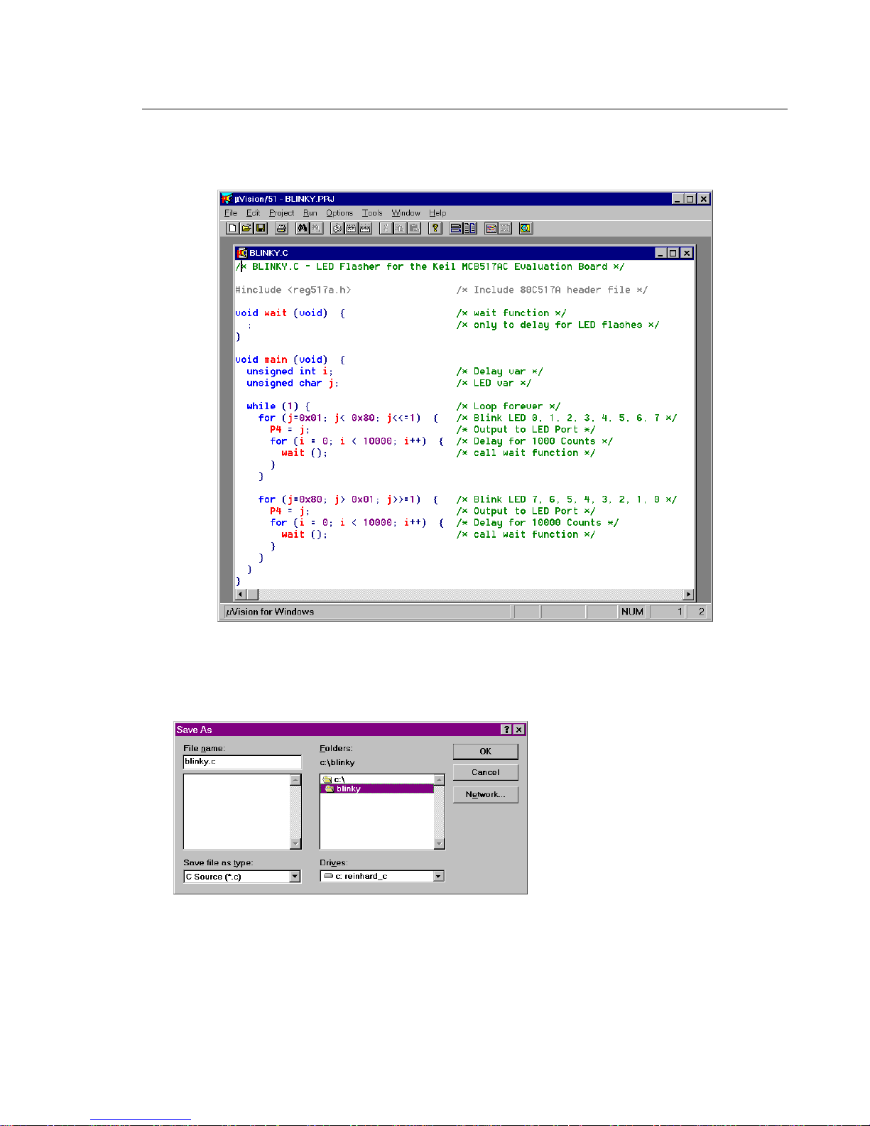
Enter the BLINKY example program shown on page 33. Your screen should
look something like the following figure.
You should save the BLINKY program after you enter it. Select the Save As…
command from the File menu and µVision displays the Save As dialog box
shown below.
To save the program as BLINKY.C, enter BLINKY.C in the File Name text box
at the top of the Save As dialog box. You may want to save the flash program
and the other files you create in a separate directory. This example uses
C:\BLINKY for the source files and project files.
Page 42

36 Chapter 4. Programming
After you save BLINKY.C, you should create a BLINKY project file. A project
file contains a list of all the source files in your project as well as the options to
use for the compiler, assembler, linker, and make facility. Additionally, the
project manager helps you compile, link, and test your target program.
To create a project file for BLINKY, select the New Project… command from
the Project menu. µVision displays the dialog box shown below. Enter the
name for the project in the File Name text box. This example uses
BLINKY.PRJ.
NOTE
You should always use PRJ as the file extension for project files.
When the project file is created, µVision displays the Project Manager dialog
box. Here, you select the source files to include in your project.
Click the Insert button and choose the BLINKY.C file you previously saved.
Then, click the save button to save your changes to the project file. To return to
the Project Manager dialog box, select the Edit Project… command from the
Project menu.
Page 43
MCB517AC Evaluation Board User’s Guide 37
When you have created a project file and inserted the source files into the
project, you are ready to set the options for the compiler, linker, and other tools.
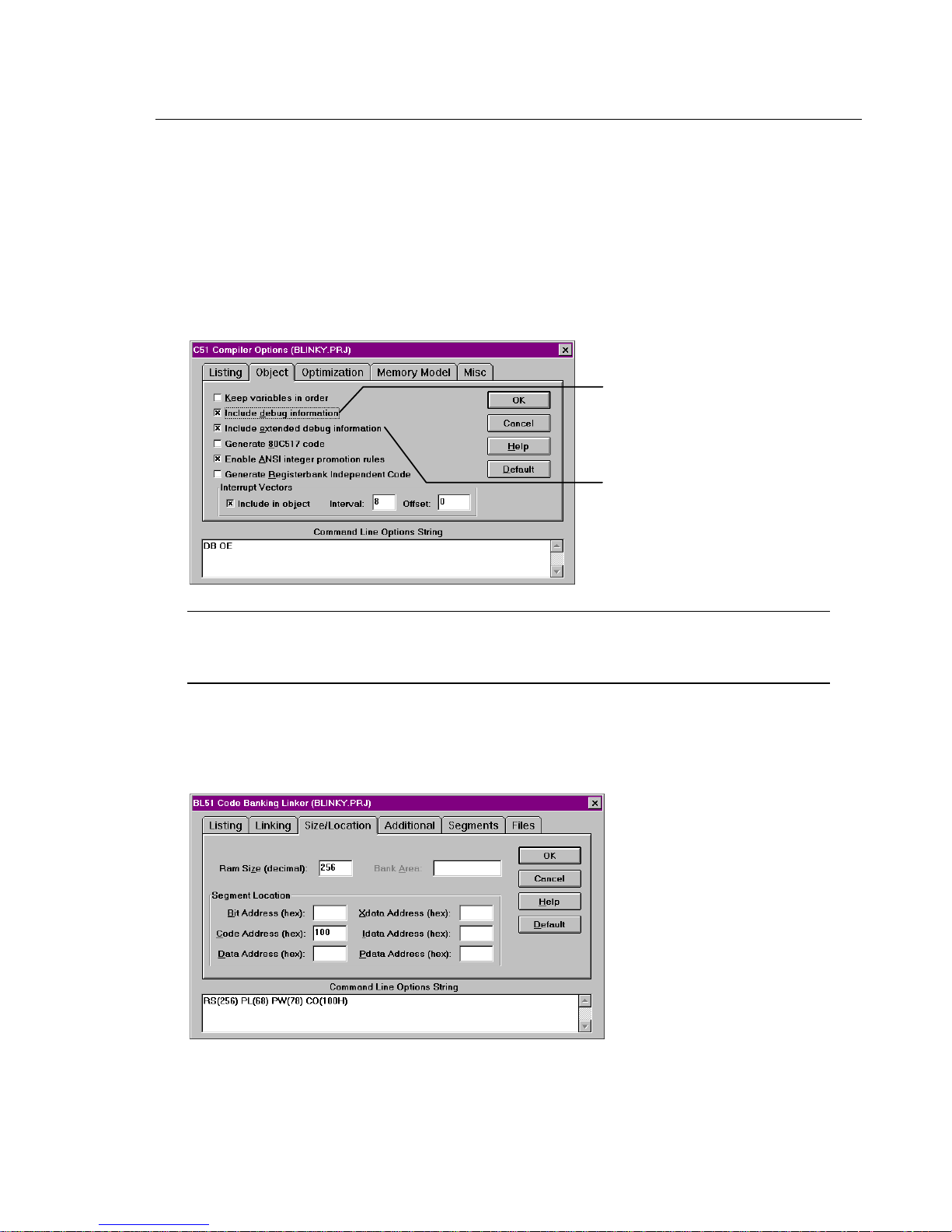
To set the C51 compiler options, select the C51 Compiler… command from the
Options menu and µVision displays the C51 Compiler Options dialog box. The
only options you need to set for the BLINKY example are ‘Include debug
information’ and ‘Include extended debug information’ for Code generation.
These controls are shown in the following figure.
Make sure to
include debugging
information in the
object file.
Also set extended
debugging information
to have all variable
types available.
NOTE
In any of the option dialog boxes, you may click the Default button to set the
controls to the default settings.
To set the L51 linker options, select the L51 Linker… command from the
Options menu. µVision displays the L51 Linker Options dialog box shown
below.
Page 44

38 Chapter 4. Programming
Enter the number 256 in the Ram Size and 100 in the Code Address text boxes
on the Size/Location tab shown above.
This creates the RAMSIZE and CODE directive that tells the linker to use up to
256 bytes of internal memory and to locate all relocatable code segments to
100H and above. This reserves the space for the interrupt vectors.
You may wish to specify the path to the 8051 tools directly in µVision. You
may do this in the Environment Pathspecs dialog box. Open this dialog box
using the Environment Pathspecs… command in the Options menu.
You may specify the path to BIN directory, the INC directory, and the LIB
directory. Additionally, you may specify a temporary directory for the compiler
and linker to use when compiling and linking.
Finally, the make options control how µVision processes the files in your
project. Open the Make Options dialog box by selecting the Make… command
in the Options menu.
Make sure you select the Run BL51 Linker radio button. This links your source
files after compiling them.
Now, you are ready to build the project. Select the Make: Build Project
command from the Project menu to begin compiling and linking. µVision
responds by compiling the BLINKY.C source file and linking it with the
appropriate library files.
Page 45

MCB517AC Evaluation Board User’s Guide 39
This process it historically called making the project. While the make is running,
µVision displays the status as shown below.
If errors occur during the make process, a message window appears. If there
were warnings or errors in your source file, you may interactively select the error
and see the corresponding line in your source file.
When make completes successfully, you are ready to begin debugging the
BLINKY program.
Using dScope to Debug the BLINKY Program
To load the BLINKY in the MCB517AC evaluation board using dScope, you
need to perform the following steps:
n Load the MON51.DLL CPU driver.
n Configure the CPU driver for the appropriate COM port and baud rate.
n Configure the CPU driver for serial break.
n Load the BLINKY program.
n Step through the BLINKY program.
Each of these steps is described in detail below.
Start dScope by selecting the dScope Debugger… command from the Run menu.
This loads dScope and sets the current path to the path in which your project file
is saved.
Page 46

40 Chapter 4. Programming
When dScope starts, a screen similar to the following displays.
Register
Window
Module
Window
To load the MON51.DLL CPU driver, type the following in the command
window.
load mon51.dll
This is shown in the following figure.
Command
Window
Page 47

MCB517AC Evaluation Board User’s Guide 41
Typically, the first time you load the CPU driver for the 8051 monitor, you must
set the COM port and baudrate. If dScope cannot determine the com port and the
baud rate automatically, the following dialog box appears informing you that
dScope could not find the target system.
When using the MCB517AC evaluation board, the baudrate should be set
according to the DIP switch S3 and S4 settings (typically 9,600 baud). You must
determine which COM port of your PC you are using.
Next, you should configure the CPU driver to enable serial breaks. To do this,
select the Configuration command from the Peripherals menu. dScope displays
the Configuration dialog box shown below.
Set Use serial
interrupt to let
dScope stop
programs running
on the MCB517AC.
Finally, you are ready to load the BLINKY program. To do so, type the
following in the command window.
load blinky /* this loads the blinky program */
g,main /* this steps over the startup code */
/* and stops on the first line of main */
Once BLINKY is loaded, the module window displays the BLINKY program as
shown in the following figure.
Page 48

42 Chapter 4. Programming
You may now single step through the BLINKY program by clicking on the
StepOver button on the right side of the module window. As you step through
the program, you should see the LEDs on the MCB517AC changing.
When you are ready to exit dScope, click on the Stop button in the module
window and select the Exit command in the File menu.
NOTE
You must stop the program execution of your target program before you can exit
dScope.
Page 49

MCB517AC Evaluation Board User’s Guide 43
External CAN Example
The following example program shows you how to access the external CAN
controller registers. You can use this CAN xdata structure to access every
register of the external CAN controller 81C90.
This very simple example reads the low nibble (bits 0-3) of CAN port 0 and
writes the data into the high nibble (bits 4-7) of CAN port 0.
#include <reg517a.h>
struct CANSTRUCT {
unsigned char BL1;
unsigned char BL2;
unsigned char OC;
unsigned char BRP;
unsigned char RR1;
unsigned char RR2;
unsigned char RIM1;
unsigned char RIM2;
unsigned char TRS1;
unsigned char TRS2;
unsigned char IMSK;
unsigned char dummy1[5];
unsigned char MOD;
unsigned char INT;
unsigned char CTRL;
unsigned char dummy2;
unsigned char CC;
unsigned char TCEC;
unsigned char TCD;
unsigned char dummy3;
unsigned char TRR1;
unsigned char TRR2;
unsigned char RRP1;
unsigned char RRP2;
unsigned char TSCH;
unsigned char TSCL;
unsigned char dummy4[10];
unsigned char P0PDR;
unsigned char P0PR;
unsigned char P0LR;
unsigned char dummy5;
unsigned char P1PDR;
unsigned char P1PR;
unsigned char P1LR;
unsigned char dummy6;
unsigned int TIME_STAMP[8];
unsigned int DESCRIPTOR[16];
} xdata CAN _at_ 0xf700;
Page 50

44 Chapter 4. Programming
void main(void) {
unsigned char value;
CAN.P0PDR = 0xf0; /* configure CAN P0 pins 0-3 for input and */
/* pins 4-7 for output */
while(1) {
value = CAN.P0PR; /* read CAN P0 port */
value <<= 4; /* shift low nibble to high nibble */
CAN.P0LR = value; /* output data at CAN P0 pins 4-7 */
}
}
Use the following command lines to compile and link the external CAN example
program or set up a project with µVision which does the same. The options are
the same as for the BLINKY example:
C51 CANPORT.C DEBUG OE
Use the following command line to link:
L51 CANPORT.OBJ CODE(0100H)
and the following command line to generate an Intel HEX file:
OH51 CANPORT
You may then use the CANPORT.HEX file to program an EPROM or the
CANPORT file to load into monitor 51 or dScope.
Page 51

MCB517AC Evaluation Board User’s Guide 45
Code Banking Example
The following example program shows you how to use code banking with the
MCB517AC. Here are 7 source modules and one BL51 configuration module
which will be located in the common area and from bank 0 to 5. When you step
through this program with dScope for Windows you will see how bank switching
works.
/*----------------------------------------------------------------------ROOT.C
Copyright 1997 KEIL Software, Inc.
------------------------------------------------------------------------*/
#include <reg517.h>
extern void func0(void);
extern void func1(void);
extern void func2(void);
extern void func3(void);
extern void func4(void);
extern void func5(void);
void main(void) {
P4 = 0; /* switch off all LED’s */
while(1) {
func0(); /* call a function in bank 0 */
func1(); /* call a function in bank 1 */
func2(); /* call a function in bank 2 */
func3(); /* call a function in bank 3 */
func4(); /* call a function in bank 4 */
func5(); /* call a function in bank 5 */
P4 ^= 0x80; /* toggle LED 7 */
}
}
Select the following settings in the L51_BANK.A51 file:
?B_NBANKS EQU 8 ; Define max. Number of Banks
?B_MODE EQU 0 ; 0 for Bank-Switching via 8051 Port
?B_RTX EQU 0 ; 0 for applications without RTX-51 FULL
; ; 1 for applications using RTX-51 FULL
;----------------------------------------------------------------------; For Bank-Switching via 8051 Port define Port Address / Bits
P6 DATA 0FAH
?B_PORT EQU P6 ; default is P1
?B_FIRSTBIT EQU 5 ; default is Bit 3
;------------------------------------------------------------------------
Page 52

46 Chapter 4. Programming
/*----------------------------------------------------------------------BANK0.C
Copyright 1997 KEIL Software, Inc.
------------------------------------------------------------------------*/
#include <reg517.h>
extern void func1(void);
void func0(void) {
P4 |= 0x01; /* switch LED on */
func1(); /* FUNCTION IN BANK 0 CALLS A FUNCTION IN BANK 1 */
P4 &= ~0x01; /* switch LED off */
}
/*----------------------------------------------------------------------BANK1.C
Copyright 1997 KEIL Software, Inc.
-----------------------------------------------------------------------*/
#include <reg517.h>
extern void func2(void);
void func1(void) {
P4 |= 0x02; /* switch LED on */
func2(); /* FUNCTION IN BANK 1 CALLS A FUNCTION IN BANK 2 */
P4 &= ~0x02; /* switch LED off */
}
/*----------------------------------------------------------------------BANK2.C
Copyright 1997 KEIL Software, Inc.
------------------------------------------------------------------------*/
#include <reg517.h>
extern void func3(void);
void func2(void) {
P4 |= 0x04; /* switch LED on */
func3(); /* FUNCTION IN BANK 2 CALLS A FUNCTION IN BANK 3 */
P4 &= ~0x04; /* switch LED off */
}
Page 53

MCB517AC Evaluation Board User’s Guide 47
/*----------------------------------------------------------------------BANK3.C
Copyright 1997 KEIL Software, Inc.
------------------------------------------------------------------------*/
#include <reg517.h>
extern void func4(void);
void func3(void) {
P4 |= 0x08; /* switch LED on */
func4(); /* FUNCTION IN BANK 3 CALLS A FUNCTION IN BANK 4 */
P4 &= ~0x08; /* switch LED off */
}
/*----------------------------------------------------------------------BANK4.C
Copyright 1997 KEIL Software, Inc.
------------------------------------------------------------------------*/
#include <reg517.h>
extern void func5(void);
void func4(void) {
P4 |= 0x10; /* switch LED on */
func5(); /* FUNCTION IN BANK 4 CALLS A FUNCTION IN BANK 5 */
P4 &= ~0x10; /* switch LED off */
}
/*----------------------------------------------------------------------BANK5.C
Copyright 1997 KEIL Software, Inc.
------------------------------------------------------------------------*/
#include <reg517.h>
void func5(void) {
P4 |= 0x20; /* switch LED on */
P4 &= ~0x20; /* switch LED off */
}
Page 54

48 Chapter 4. Programming
Using µVision to Create a Banked Program
For this example we assume that you are already familiar with µVision
concerning how to set up a project. In this example only the difference to a
banked application is explained. In addition to a non-banked application you
have to perform the following steps:
n Set the BL51 linker options for a banked project.
n Set the make options for a banked project.
n Set up a project for a banked application.
Each of these steps is described in detail below.
To set the L51 linker options, select the BL51 Linker… command from the
Options menu. µVision displays the BL51 Linker Options dialog boxes shown
below.
Select code banking
Set the Bank Area to
8000H, 0E7FFH
Page 55
MCB517AC Evaluation Board User’s Guide 49
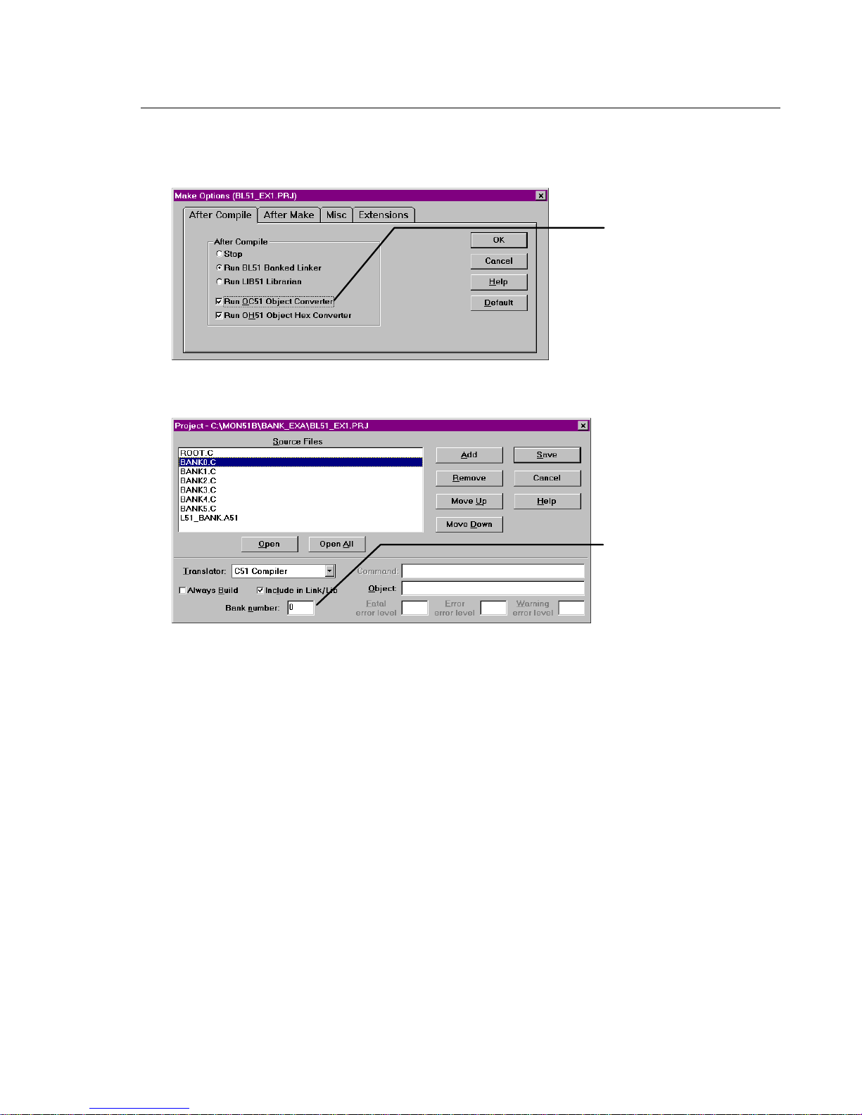
To set the Make options, select the Make… command from the Options menu.
µVision displays the Make Options dialog box shown below.
Select OC51 to get a
separate OMF file
for each bank.
Use the following project setup to build a banked application:
Enter a bank number
for the selected
module or no bank
number for common
area.
For this example please select the common area (no bank number) for the
module ROOT.C and L51_BANK.A51, bank number 0 for module BANK0.C,
bank number 1 for module BANK1.C and so on.
After building the project, you can load it into dScope for Windows or you can
program an EPROM by using the 6 generated HEX files.
Please note that it is absolutely necessary to use MON51B.DLL with dScope for
Windows instead of MON51.DLL when you have a banked application. Also
make sure to set the DIP switches S1 and S2 both to ON position.
Page 56

50 Chapter 5. Using the 8051 Monitor
Chapter 5. Using the 8051 Monitor
The MCB517AC comes ready-programmed with the Keil Monitor51. The
monitor programmed in the Monitor EPROM is setup to run at various baudrates
and serial interfaces depending on the setting of DIP switches S3 and S4.
You may use the MON51 DOS terminal program (MON51.EXE) or the dScope
for Windows debugger/simulator to quickly download and test your programs.
Please note that a banked application cannot be debugged with MON51; you
have to use dScope for Windows in this case.
MON51 Terminal Program
The MON51 terminal program communicates with the 8051 monitor using one
of your PC’s serial ports. MON51 lets you:
n Display the contents of the 8051’s memory areas in ASCII and hexadecimal,
n Interactively change memory contents,
n Display and change register contents,
n Initialize memory with constant values,
n Disassemble the code area,
n Assemble in-line code,
n Run programs with breakpoints in real-time,
n Create up to 10 program breakpoints,
n Single-step through your program,
n Step over subroutines,
n Upload and download Intel HEX files and OMF-51 object files,
n Display an online command help menu.
Page 57

MCB517AC Evaluation Board User’s Guide 51
Starting the MON51 Terminal Program
Use the following command line to start the MON51 terminal program.
MON51 COM1|COM2|COM3|COM4 INT14|NOINT BAUDRATE(n)
where:
COM1: … COM4: Specifies the serial port to use. You may use the COM port
number as an abbreviation. COM1 is used by default.
INT14 Specifies that the serial interface is accessed through the
BIOS software interrupt 14H. Direct hardware interrupts are
not used. You may use
NOINT Specifies that the serial interface is polled. Hardware
interrupts are not used. You may use
for
NOINT.
I as an abbreviation for INT14.
N as an abbreviation
BAUDRATE(n) Specifies the baud rate to use. If this option is omitted,
MON51 defaults to 9600 baud. The value
n
specifies the
baud rate. Valid baud rates are: 300, 600, 1200, 2400,
4800, 9600, 19200, 38400, and 57600. You may use
an abbreviation for
BAUDRATE.
BR as
The command-line parameters of the MON51 terminal program may be set using
the environment variable MON51. You may set this environment variable using
the DOS SET command. If no parameters are included on the command line,
MON51 uses the MON51 environment variable settings. If the environment
variable settings are used, the MON51 terminal program displays the following
message:
ENVIRONMENT STRING: MON51=<parameters>
Page 58

52 Chapter 5. Using the 8051 Monitor
Utility Commands
The MON51 terminal program supports the following commands:
n Exit Exit MON51 and return to DOS.
n F1 Exit MON51 and return to DOS.
n F2 Transmit the contents of a file.
n F3 Echo the contents of the screen to a file.
n Help Display the help menu.
n ; Comment lines.
Exit: Exit MON51 and Return to DOS
This command closes all files and returns to DOS. For example:
#EXIT
F1: Exit MON51 and Return to DOS
When you enter
EXIT MON51 (y or [n])
F1 or Alt+1, MON51 responds with the following prompt.
Enter Y to exit MON51, close all files, and return to DOS.
F2: Transmit the Contents of a File
When you enter
Input File:
F2 or Alt+2, MON51 responds with the following prompt.
Here, you may enter a file from which MON51 inputs and interprets commands.
For example:
Input File: MYINIT.CMD <cr>
directs MON51 to read the contents of the file MYINIT.CMD and interpret them
as commands. You may press
Ctrl+C to stop retrieving commands from the file.
Page 59

MCB517AC Evaluation Board User’s Guide 53
F3: Echo the Contents of the Screen to a File
When you enter
Output File:
F3 or Alt+3, MON51 responds with the following prompt.
Here, you may enter a file where the contents of the screen will be copied. For
example:
Output File: DEBUG.PRN
directs MON51 to write the screen contents to DEBUG.PRN. Press F3 or Alt+3
to stop writing screen changes.
If you enter the name of a file that already exists, MON51 responds with the
following prompt.
Overwrite existing file (y or [n])?
Enter Y to overwrite the file.
HELP: Display the Help Menu
When you enter the help command, MON51 displays a brief description of all
8051 monitor commands.
;: Comment Lines
Any line starting with a semicolon is a comment. Comments may be entered
after a command. For example,
#DC 0x4000 ; Show code at 0x4000
MON51 ignores any text after the semicolon. Comments are useful when you
F2 to transmit the contents of a command file.
use
Page 60

54 Index
Index
FLASH..........................................31
2
20V8...................................................13
Exit Command....................................50
External CAN Example Program.......41
8
8051 Monitor......................................48
80C517 / 80C517A Jumper..................9
80C517 CPU ......................................12
80C517A CPU....................................12
B
BAUDRATE......................................49
BR.......................................................49
C
CAN Bus ............................................14
CAN Ports ..........................................15
Circuit Description.............................11
Code Banking Example Program.......43
COM1.................................................49
COM2.................................................49
COM3.................................................49
COM4.................................................49
Comment Lines ..................................51
Configurartion Jumper .........................9
Configuration .....................................12
Configuring the MCB517AC...............5
Contents of MCB517AC Kit................1
F
F1 Command......................................50
F2 Command......................................50
F3 Command......................................51
FLASH Example Program .................31
H
Hardware............................................11
Hardware Requirements.......................3
Help Command...................................51
I
I/O Device ..........................................13
INT_CAN DIP Switch .........................6
INT14 .................................................49
Introduction ..........................................1
J
Jumper
Default Setting................................5
K
Kit Contents..........................................1
D
Decode Logic .....................................13
DIP Switch ...........................................5
Default Settings ..............................5
DIP Switches........................................6
Document conventions........................iv
E
Example Program
Code Banking...............................43
External CAN...............................41
L
LED DIP Switch...................................8
M
MAX232.............................................14
Memory Device..................................13
MON51 environment variable............49
MON51 Terminal Program ................48
Monitor Data Space............................29
Monitor DIP Switch .............................7
Monitor EPROM Addresses...............26
Monitor Interrupt Vectors...................29
Page 61

MCB517AC Evaluation Board User’s Guide 55
Monitor Memory Map .......................27
Monitor Modes.....................................9
Monitor Program................................ 48
Monitor Status Display ......................10
N
NOINT...............................................49
O
OWEoff................................................8
P
PAL.................................................... 13
PAL Equations...................................22
PE/Soff.................................................8
Power Supply Circuitry......................12
Printed Board Assembly ....................21
Programming......................................27
Prototyping Area................................ 15
Push Button........................................13
S
S_CAN DIP Switch .............................6
S1 DIP Switch......................................7
S2 DIP Switch......................................7
S3 DIP Switch......................................6
S4 DIP Switch......................................6
Schematics .........................................17
Serial Port...........................................14
Setup.....................................................3
Software Requirements........................3
Status LEDs........................................13
T
Technical Data ...................................22
U
Using µVision ....................................32
Using dScope .....................................37
W
Writing Programs for the 8051
Monitor............................................30
 Loading...