

Page 1

KEF R&D
R Series 2018
Page 2

2
Page 3

Contents
Introduction 5
Philosophy 5
Objectives 5
The cabinet 6
Visual design 6
Minimising panel sound radiation 6
Directivity and diraction 8
Ports 9
Resonance inside the cabinet 10
Organ pipe resonances 10
Turbulence 10
Drive units (Drivers) 10
Bass drivers 10
Diaphragm 11
Magnet system 11
Spider (Damper) 12
Uni-Q array 12
Filling in the gaps 13
Midrange 13
Cone and surround 13
Magnet system 14
Tweeter 14
Diaphragm assembly 14
Tangerine waveguide 15
Rear loading 15
Crossovers 16
Model Range 18
R3 18
R5 19
R7 20
R11 21
R2c 22
R8a 23
Summary 24
Acknowledgements 24
References 24
3
Page 4
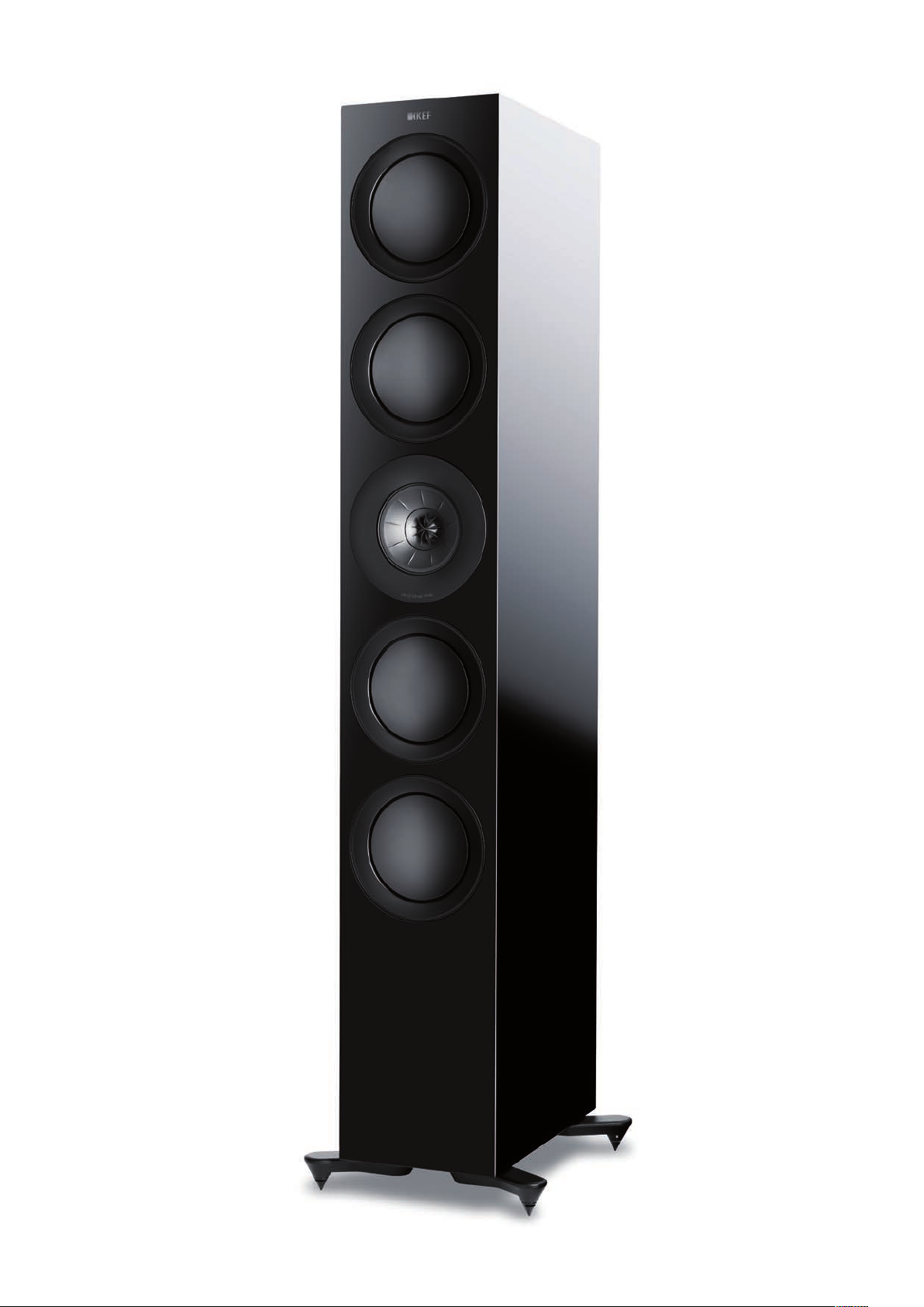
R11 in Black Gloss nish
4
Page 5

Introduction
Objectives
It is 7 years since the rst R Series products were introduced.
In that time, KEF’s Research and Development work has
continued and its best technology has improved. The fruits of
this work can be seen in the 2014 Reference Series and the
Blade 2. Behind the R series 2018 are a wealth of technical
updates and improvements – some trickle-down from the
Reference and Blade projects and some specic to the new
series. The result is a signicant step up in performance and
a purity of sound that’s clear from the rst listen.
Philosophy
“Of all art, music is the most indenable and the most
expressive, the most insubstantial and the most immediate,
the most transitory and the most imperishable. Transformed
to a dance of electrons along a wire, its ghost lives on. When
KEF returns music to its rightful habituation, your ears and
mind, they aim to do so in the most natural way they can…
without drama, without exaggeration, without artice.”
Raymond Cooke, KEF founder
Loudspeakers have a dicult job, not always fully appreciated.
They must take a 1-dimensional signal and turn it into a
3-dimensional experience.
Stereo – the simplest common conguration – uses just
two loudspeakers to create a complete sound stage for the
listener. Imagine throwing a handful of gravel into a pond and
trying to recreate the same ripple pattern by dropping just
two pebbles into the pond spaced by about 2 metres. It can’t
be done and we haven’t even considered height! Stereo is
an illusion that, fortunately, seems to work remarkably well.
Nevertheless, there are some clearly dened attributes that
separate good loudspeakers from mediocre ones:
The sound must come from the drivers and no other part of
the structure. The most common form of unwanted added
sound is radiation from the cabinet. The panels are relatively
large in area and don’t have to move much to colour the
true sound.
These words were penned shortly after KEF’s founding in
1961. Cooke was an avid music acionado and his mission
from the outset was to enable a wide audience to derive
the same pleasure from music as he did. He sought to
deliver to his customers the immersive experience of the live
performance through recordings.
Cooke realised that this could only be achieved by a scientic
understanding of sound and its reproduction, concentrating
his eorts on loudspeakers – the last link in the recording
chain and probably the most dicult in that they have to
work in an unknown 3-dimensional environment. Never
afraid to employ the most capable engineers and provide
them with the latest and most eective tools, Cooke
established a philosophy that still exists today.
KEF engineers continue to pursue this scientic endeavour,
today using tools and technology that were unavailable to
Cooke in those early days, never forgetting that all the science
in the world is useless unless it brings better performances
and greater pleasure to the user. The listening experience is
still the nal arbiter in deciding whether or not the science
is eective, but without it progress cannot be measured and
the way forward cannot be understood.
A loudspeaker should have controlled dispersion. If the
character of sound varies too much with angle, the
3-dimensional sound stage cannot be accurately formed
and an acceptable listening position is very restricted. But
omni-directionality is not desirable either. The acoustics of
the listening room become more intrusive and can swamp
any attempt to recreate the acoustic environment of the
original performance.
The sound quality should be the same at all levels. The
dynamic range of music (the quietest to the loudest sounds) is
high and, in order to reproduce it accurately, the loudspeaker
must not compress the sound nor to come to life only at
relatively high levels.
There should be no harmonic or intermodulation distortion
– the creation of sounds at frequencies that are not present
in the original.
There should be no time or temporal distortion. This can
come from resonances, where the sound hangs on at
discrete frequencies, or diraction, the re-radiation of sound
at discontinuities in the structure that is delayed relative to
the direct sound from the drivers.
5
Page 6

Now, it’s all very well to say that there must be none of
anything, but we don’t live in a perfect world. The job of
the engineer is to minimise all these undesirables, ideally to
a level below which they are audible. However, sometimes
there are conicting issues and, in this case, the engineer
has to gauge the lesser of two evils. For example, low bass
at high volumes is extremely dicult for smaller cabinets to
achieve. However, smaller cabinets may be preferred for
their visual quality.
Visual design
All R Series cabinets are designed to look good. They have
clean lines, there is a choice of nishes – black gloss, white
gloss, walnut – and the frontal aspect is slim (more of that
later when we discuss temporal accuracy). The quality of
t and nish is high and, for those who prefer not to see
drivers, there is the option of magnetically attached grilles.
This brings us to the subject of visual design. Loudspeakers
must be considered a legitimate piece of furniture in the
living environment. They should, in short, look good.
The cabinet
We have seen that the objectives of the cabinet are:
• To look good.
• To emanate a minimum amount of sound.
• To maintain temporal accuracy.
• To help control directivity.
There is a fth attribute that the cabinet should also have and
it is stability. The most obvious criterion is that it should not
be easy to knock the loudspeaker over. Loudspeakers can
be heavy and could cause discomfort or injury should they
fall on anyone, especially a small child. There are furniture
standards that cover this and the device should return to an
upright position if it is leaned over up to 10°.
Also important to the audiophile is that the cabinet should
not be allowed to rock when the drivers operate. If this
happens, the bass quality is impaired. It may be described as
“softening” and the eect is most noticeable on percussive
bass, often referred to as “slam”.
All the oor-standers in the range are equipped with spike
feet that pierce through carpeting and prevent any rocking.
These spike feet are tted to outriggers that extend beyond
the boundaries of the cabinet and provide the necessary
static stability.
The loudspeakers are optimised for when the grilles are
not tted and they are ideally removed for serious listening,
even if they are tted when the loudspeakers are not in use.
However, the grilles are designed to have the minimum eect
on sound quality.
Minimising panel sound radiation
The panels of the cabinet may be excited by two mechanisms:
• Reaction forces from the drivers – as the driver
diaphragm moves back and forth there is a reaction
force on the chassis (basket) that is them transmitted to
the cabinet.
• Forces from pressure in the air contained inside
the cabinet.
If cabinets suer these problems, it is worth asking why we
need them at all. The answer lies in the drivers themselves.
They radiate the same amount of sound energy to the rear
as they do to the front. Unfortunately, the rear radiation
is out of phase with that from the front and, if the two
are allowed to mix, they cancel each other out. The
ability of sound waves to go around corners depends on
the wavelength relative to the size of the object. A good
analogy is to consider waves in the sea. They readily wrap
round small rocks but are reected from clis. So it is with
a loudspeaker driver. The lower the frequency the more the
sound will wrap around the driver. A driver suspended freely
in air will have no bass. We need a mechanism for blocking
this interaction and the cabinet serves to do this.
Stand-mount systems should always be mounted on a stand
that aords similar stability.
There are two common ways of reducing panel output:
• Adding bracing between the panels to increase stiness.
• Adding damping pads to the panels.
The idea behind method 1 is that the increased stiness
reduces panel motion. What it does in fact is to raise
the frequency of any resonances. A similar eect would
6
Page 7
occur if the panel thickness were to be increased. This
might be of some benet if the loudspeaker system has
separate enclosures for dierent drivers, like in R Series.
The resonances in any one enclosure may be pushed out
of the working frequency range of the driver housed in
it. However, there is a drawback to this method. The bass
resonances may be pushed into the midrange, where the ear
is more sensitive.
The addition of damping pads to the panels does work and
was used on the R Series 2011. The pads are usually made
of some bituminous material that converts deformation into
heat and thus reduces the vibrational movement of the base
panel. Unfortunately, most commercially available pads are
designed to damp resonances in the thin metal panels used
on cars. Their ecacy depends on matching the mechanical
impedances of panel and damping pad and the match
between the pads and wood is not ideal.
KEF Engineers developed a technique, originally for the
LS50 loudspeaker system but applied to all R Series 2018
systems, that combines the two approaches and is more
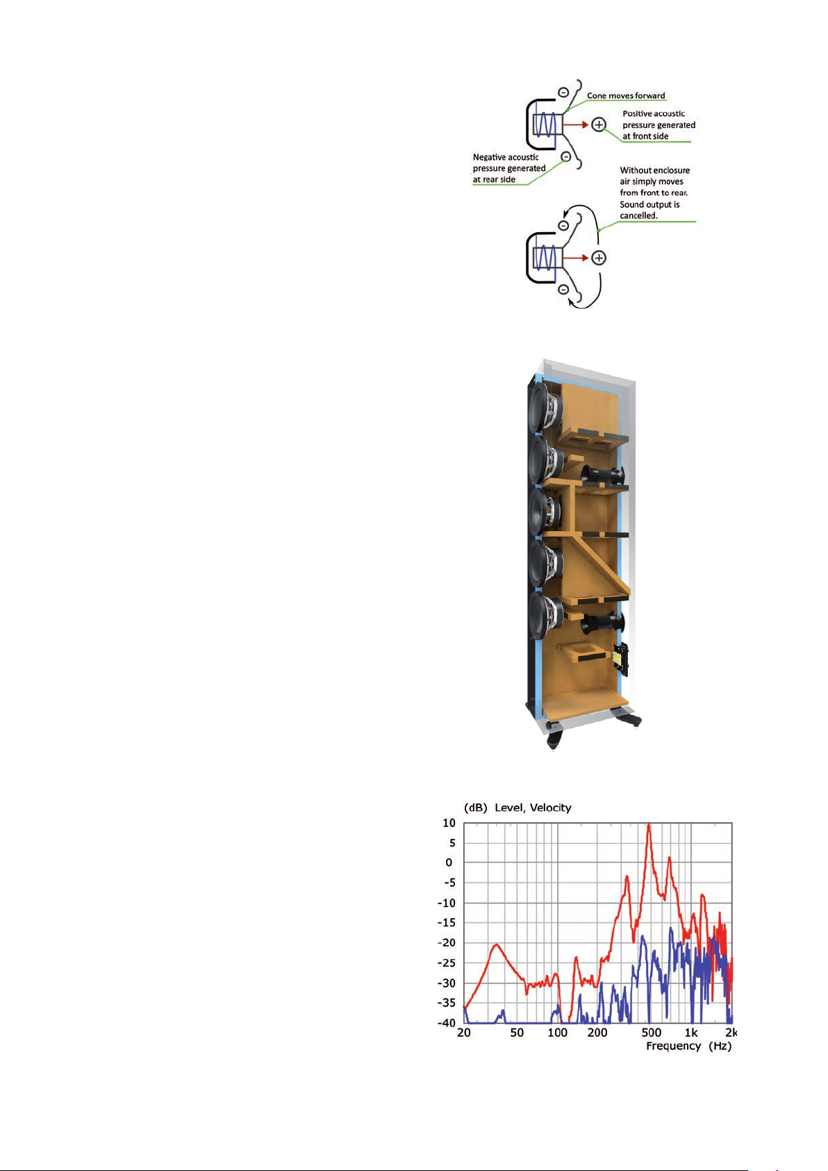
eective than both. The technique, called damped bracing,
consists of strategically placed wooden braces that, instead
of being rigidly coupled to the panels are joined via a lossy
interface. The braces are placed where the panel movement
would otherwise be greatest and the lossy layer, like normal
damping pads, converts the energy into heat.
Figure 1
Driver in free air
Additional damped braces are situated at the back of each
driver, which reduce the level of reactionary vibration
transmitted from the driver to the cabinet.
The reduction in sound output from the cabinet varies
model by model, depending on the exact geometry, but
is typically of the order of 20dB, as shown in gure 3.
Cabinet sound radiation is highly distorted and, at the
resonance frequencies, causes time-smearing as the output
hangs on. The increase in clarity wrought by the damped
bracing is readily noticeable, is probably best in class for
single-enclosure multi-way loudspeaker systems and is
comparable to the best high-end systems.
Figure 2
R11 Cabinet construction
Figure 3
Panel vibration — without damping — with damped bracing
7
Page 8
Directivity and diraction
Both these attributes are aected by the geometry of the
cabinet and so are lumped together here.
It is not often appreciated that the directivity of any
loudspeaker system is controlled as much by the geometry
of the cabinet as by the size of the drivers. In this, the
engineer is helped by the fact that listeners may occupy
positions that vary in the horizontal plane, but ear height
diers little. It follows that it is much more important to keep
the horizontal dispersion of the loudspeaker wide than is it
the vertical.
It was stated above that each of the R Series cabinets is slim.
Not only does this minimise the cabinet’s visual impact, but
it allows the wide horizontal directivity required to create
a stable sound stage for all listeners. The larger systems in
the range employ multiple small-diameter drivers rather that
a single larger diameter one precisely so the cabinet can
remain slim and maintain the desired horizontal directivity.
There is a small reduction in vertical directivity – but this is
not a problem at bass frequencies, where the wavelength
is long compared to the driver spacing. In the more critical
midrange, the Uni-Q array gives far better vertical directivity
than can be had from multiple vertically-displaced drivers.
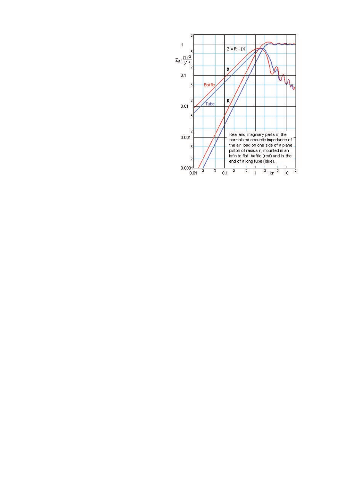
Acoustic Impedances after Beranek - Note that it is the 20dB/decade
Figure 4
slope of the real part that aects the driver response in its working range
inaudible and the driver’s response smoother. However,
the radius of curvature must be of the same order as the
wavelength of the sound, the overall width of the cabinet
increases, making it more visually intrusive, and the cost of
manufacture increases considerably. So, whilst this technique
is often found on the most expensive systems, it is not
appropriate to the R Series.
Diraction – the bending of wave motion around corners –
can cause time smearing. Some of the sound energy generated
by the drivers travels along the front surface or bae of the
cabinet and, if it reaches an edge, re-radiates as shown by
gure 5. It’s rather like having small secondary drivers spread
along the edge of the cabinet. But this radiation is delayed
compared to the sound coming directly from the driver,
approximately by the time it takes to travel from the driver
to the edge. There is thus a degree of time smearing that
impairs the clarity of what the listener hears. Not only
that, but there is perturbation of the frequency response
because this secondary radiation goes in and out of phase
with the direct sound as the frequency and commensurate
wavelength vary.
The classic way of dealing with this eect is to round the
sharp corners of the cabinet. In simple terms, this can be
regarded as creating a multitude of edges, each with much
lower levels of secondary radiation. The total level is much
lower with the result that the time smearing becomes
With most manufacturers, the diraction eect is something
to be suered and not talked about. But the fact that we
are talking about it here indicates that KEF engineers have
successfully tackled the problem by a bit of lateral thinking
made possible by the fact that Uni-Q drivers are used
throughout.
It has been known for many years, and is illustrated by Leo
Beranek in his book “Acoustics”, published in 1954, that the
acoustic impedance of a driver (the interface between the
diaphragm motion and radiated sound) is smooth when
mounted both in an innite bae (as expected) and at the
end of a long tube the same diameter as the diaphragm.
This latter situation comes about because the dispersion of
the driver is such that it doesn’t acoustically “see” the edges
of the tube. The physics of this situation can be bent a little
and it can be shown that a driver mounted in a cabinet not
much wider than itself has a very low level of diraction. It’s
not perfect, but the level of diraction is much lower than it
would otherwise be.
8
Page 9
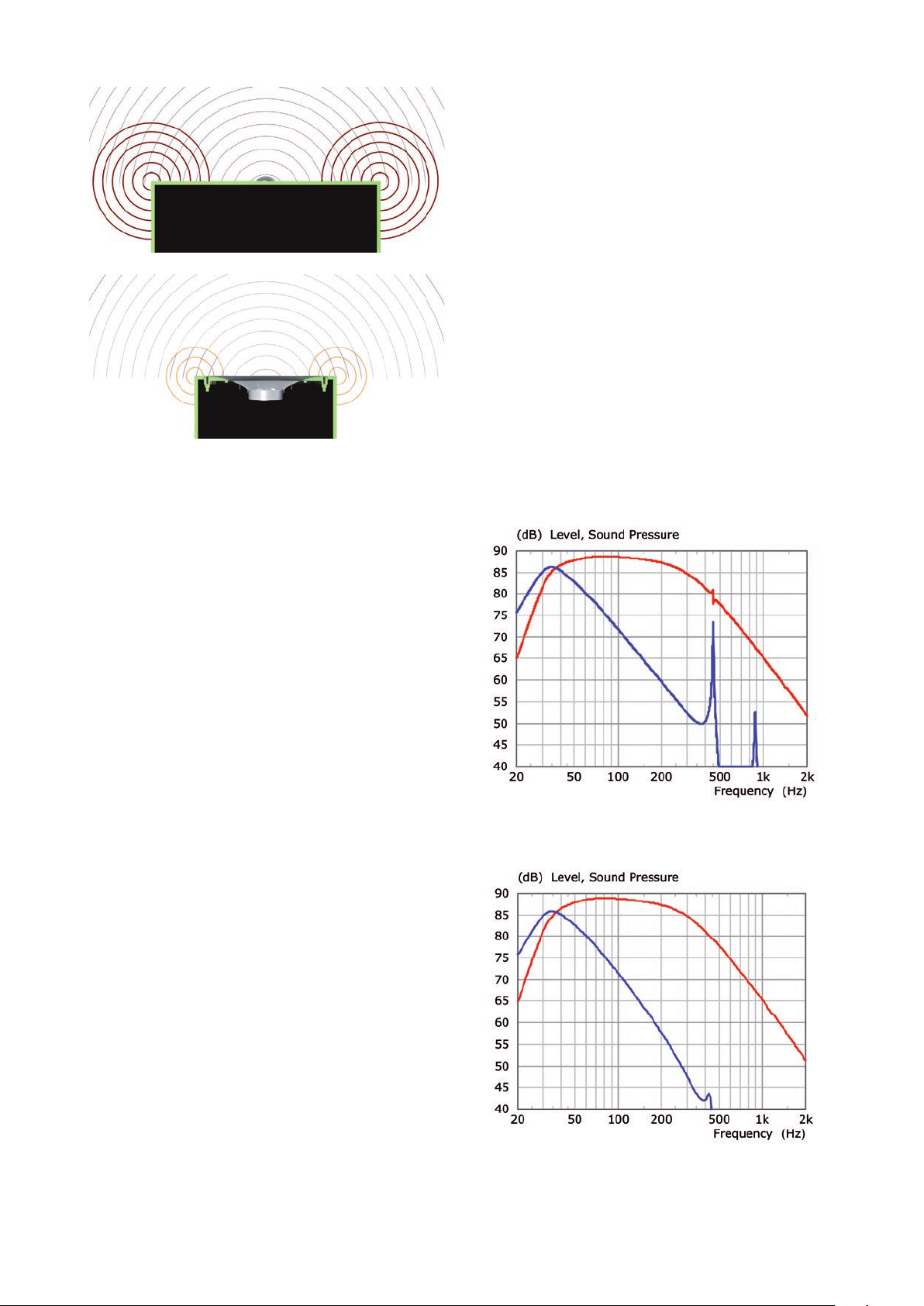
Figure 5
Simulation of tweeter output
top – tweeter mounted directly in bae
bottom – tweeter in Uni-Q array with shadow are— direct — diracted
If we look at the drivers used in the R Series systems, we
can see that the bass drivers follow this requirement, but the
midrange and tweeter drivers do not. Normally, the tweeter
would be the most to suer because it is much smaller than
the width of the cabinet, which is determined by the diameter
of the bass drivers. However, in the Uni-Q driver (more of
which later), the tweeter res into an acoustic waveguide
formed by the midrange diaphragm and it is the diameter of
this relative to the width of the cabinet that determines the
level of diraction.
Ports
Ports are used to augment bass response. They have the
dual advantage that they enable a lower cut-o frequency
than closed-box systems for the same size of enclosure and,
within the operating range of the port, the bass driver moves
less, thus lowering distortion.
Ports are not without their drawbacks, however.
• They can be a window to resonances in the air cavity
inside the cabinet.
• At midrange frequencies, they act rather like an organ
pipe and exhibit a series of resonances.
• They can be a source of noise if turbulence is allowed
to happen as air vents out at each end of the port
(so-called chung).
KEF engineers have tackled each of these potential problems.
There is more work to be done, because the diameter of the
midrange (for other reasons) is smaller than that of the bass
drivers, and it is here that the lateral thinking comes into play.
Around the Uni-Q driver array is what is normally called a
trim ring. Not simply a decorative piece, the R Series trim
ring is specially shaped and engineered. It increases the
eective diameter of the waveguide such that the driver
array “sees” the edges of the cabinet much less than if it
were mounted normally. Hence the name “Shadow Flare”.
The level of secondary radiation is decreased, resulting in
less time-smearing, greater clarity and a smoother response.
This technique was originally developed for the Reference
Series products and illustrates our trickle-down philosophy.
Simulation of bass driver + port — and port only —when the port is
Figure 6
placed close to the node of internal resonances.
Figure 7
Simulation of bass driver + port — and port only —when the port is
placed close to the antinode of internal resonances.
9
Page 10
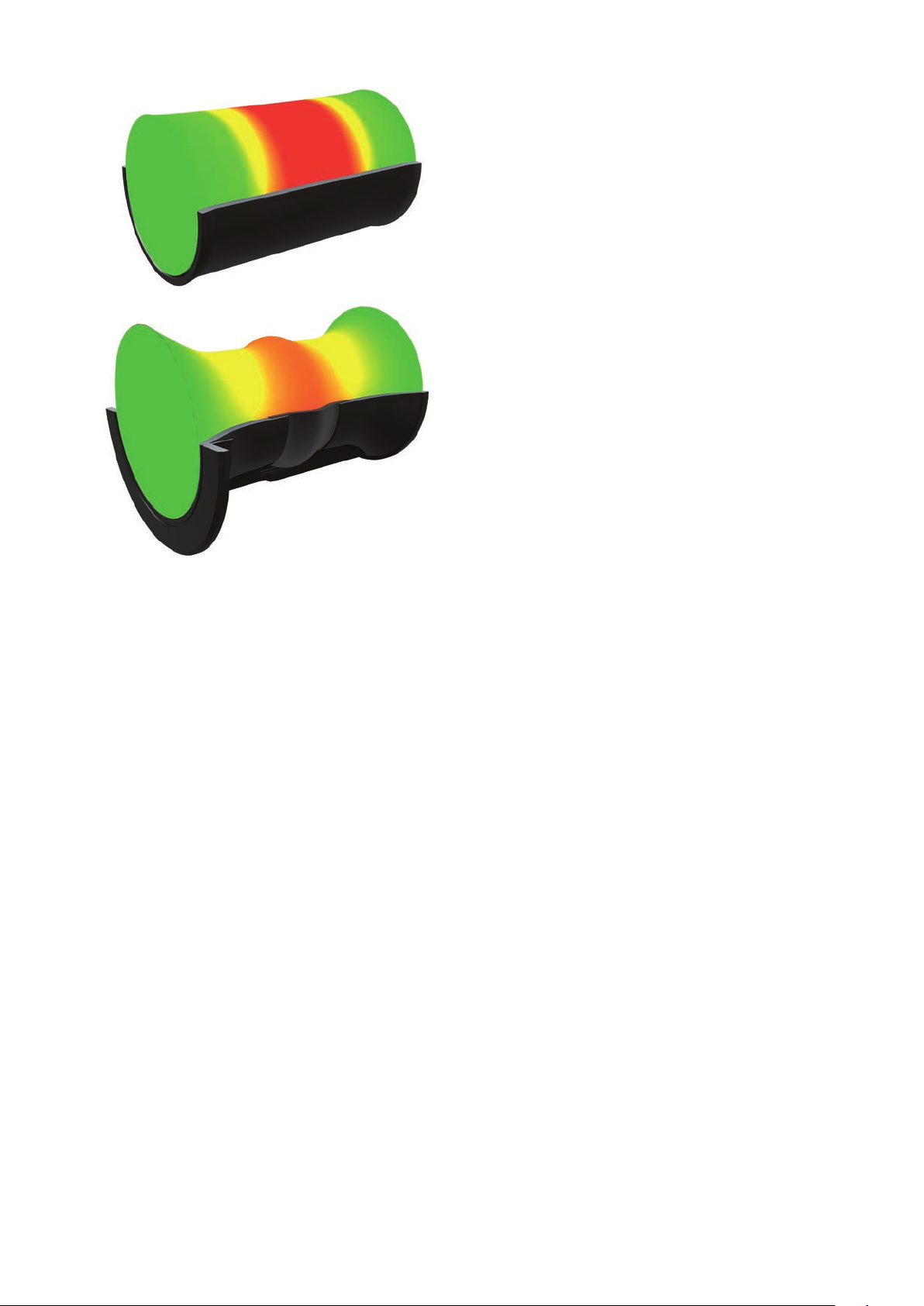
Pressure of the rst “organ pipe” resonance in a port Top –
Figure 8
rigid walls and no end areBottom – exible walls and end ares
Organ pipe resonances
These resonances within the port itself can be drastically
reduced if the walls of the port have a degree of exibility.
Instead of the normal rigid plastic, the walls are fabricated
from closed-cell foam. Originally developed for the LS50
loudspeaker, this technique dramatically reduces the pressure
variations inherent in these higher frequency resonances and
renders them less audible. Figure 8 illustrates this technique
using Finite Element Analysis (FEA), where the colour scale
from green through to red indicates the level of air pressure.
Turbulence
This occurs at both ends of the port as the air exits the
port either to the open air or the air enclosed within the
cabinet. The solution is to are both ends of the port. The
progressive expansion of the air aorded by the aring
reduces turbulence and thus audible chung. It should be
noted that, if turbulence is allowed to develop, not only is
it audible, but the performance of the port changes with
sound level, impairing the dynamic range of the loudspeaker.
Resonances inside the cabinet
The port(s) are positioned on the rear panel of the cabinet.
This has two advantages:
• Resonances inside the cabinet are at relatively high
frequencies and the sounds are not directed towards the
listener.
• There is more freedom on the rear panel compared
to the front in positioning the port so it is placed close
to antinodes (nulls) of the resonances, so less energy is
transmitted through the port.
To illustrate this last point, gures 6 & 7 show the dierence
in output when the port is placed at a node and an antinode
of an internal resonance. For the rst of these measurements
there is no wadding inside the cabinet, so the eect is made
clearer. The resonance can clearly be seen in the total
response.
When the ports are optimally placed and the wadding
added, the resonances are greatly depressed and cannot be
detected in the overall response.
Drive units (Drivers)
All but one of the systems are 3-way – they have one or
more bass drivers, a midrange driver and a tweeter. The
midrange driver and tweeter are combined into a single
array known as Uni-Q. The only 2-way in the series utilises a
bass-midrange driver instead of a dedicated midrange driver
in its Uni-Q array.
Bass drivers
Whether the system contains one, two or four bass drivers,
the design remains the same, save for the impedance of
each individual driver. The number of bass drivers simply
determines the maximum loudness of the system for a given
level of distortion. Note that, when there is an even number
of bass drivers, these are symmetrically arranged above and
below the Uni-Q array to preserve a virtual point source
over the full range.
10
Page 11
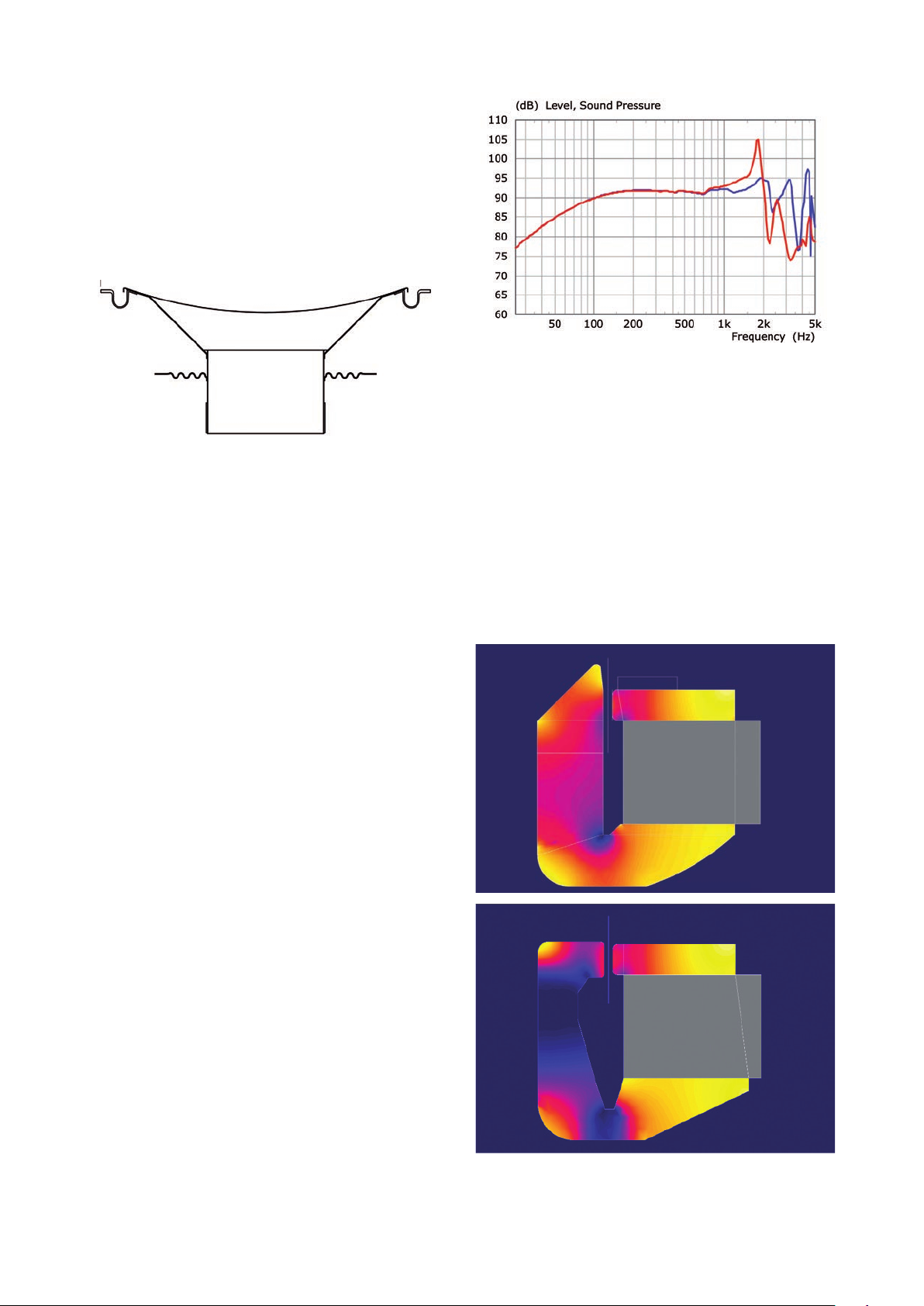
Diaphragm
This is a 2-part structure, comprising a shallow concave
aluminium front skin connected to the driving voice coil by a
more conventional paper cone (see gure 9).
Cross-section of bass driver moving parts
Figure 9
The aluminium skin has a shallow prole to minimise
perturbation of the response of adjacent drivers as a result
of diraction.
The cone itself is vented to allow free movement of air as
the diaphragm assembly moves back and forth. The static
centre pole of the magnet structure causes the volume of
air between the paper cone and the front aluminium skin
to vary with diaphragm position and this must not become
trapped, otherwise the air will be pumped through the
narrow apertures of the magnet system and cause noise.
— Response of non-optimised bass driver — Response of optimised bass driver Panel
Figure 10
is not excited.
Magnet system
With the new series, the magnet system has been totally
redesigned. One of the key objectives is to keep the magnetic
ux density seen by the voice coil as constant as possible
with coil position.
The front aluminium skin provides the stiness necessary to
provide pistonic radiation and therefore temporal accuracy
within the working range of the driver. However, like all sti
materials, the stiness is not innite and at some frequency
diaphragm breakup sets in and the Q (sharpness) of the
resonances is high – the response peaks at resonance can
be as much as 20dB above the pistonic response. Such
resonances are not readily suppressed by the relatively
gradual attenuation of the crossover network and, if left
unchecked, will cause colouration.
To reduce the intrusion of these higher-frequency resonances,
the paper cone is joined to the aluminium skin at a nodal
ring, not at the periphery. The nodal ring is an antinode of
the lowest resonance and, when driven there, the resonance
Figure 11
Finite Element Analysis (FEA) of
Top – 2011 R Series bass driver magnet system
Bottom – 2018 R Series bass driver magnet system
11
Page 12
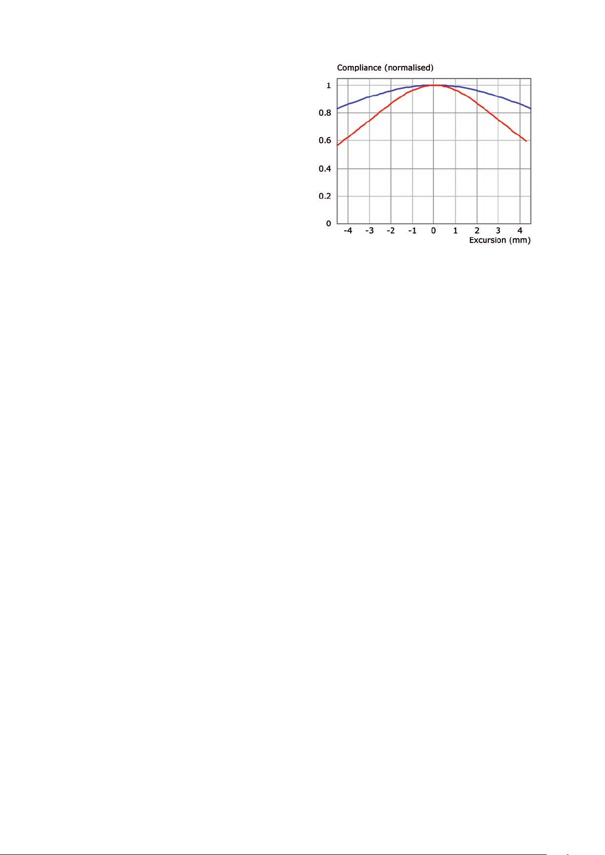
To this end, the old magnet system featured an extended
centre pole that balanced the solid material that connected
to the back plate. However, this design is still somewhat
asymmetric, with the result that the force on the voice coil
was also asymmetric, introducing more distortion than is
necessary. Further, the asymmetric nature of the metalwork
caused the coil’s inductance to vary with position, altering the
termination, and therefore the equalisation, of the crossover.
The new design is more complex and features a so-called
T-shape pole (see gure 11).
This is more symmetric than the older design and, with the
bulk of the centre pole being further from the voice coil,
lowers both the coil’s absolute inductance and its variation
with position. The result is a useful reduction in even-order
harmonic distortion.
Note, too, the undercut in the back plate that allows greater
coil movement before the coil hits the back plate.
Another feature of the new design can be deduced by
looking at the magnetic permeability in the metalwork.
The darker the colour, the lower the permeability and, where
it is almost black, the metalwork is saturated. This has two
advantages for the performance:
• The saturation limits the ux density in the coil gap and
so this remains constant regardless of the inevitable
production tolerances in magnet strength.
• Saturation further reduces the absolute level of inductance
of the voice coil and, with it, further educes the variation
in ux density that would normally occur as the coil
moves back and forth in the gap.
Spider (Damper)
The spider, or rear suspension, contributes to the linearity
of coil movement in addition to the magnet system. In this
case, as we’re dealing with symmetry, it’s the odd-order
harmonics that are mostly aected. The new spider design
allows greater linear movement and a commensurate
reduction in distortion, clearly illustrated in gure 12.
Suspension compliance as a function of diaphragm displacement
Figure 12
— Old spider — New spider
Uni-Q array
The Uni-Q array has been the mainstay of virtually all KEF
loudspeakers since its introduction in 1988. It delivers the
holy grail of loudspeaker design in that all sound appears to
emanate from the same point in space. Coaxial loudspeakers
had been around for many years before the introduction
of Uni-Q, but the tweeter was never time aligned with the
midrange or bass/midrange driver it was partnered with.
Either the tweeter was in front of the larger driver, which
brought the added disadvantage that the tweeter impaired
the response of the driver it was in front of, or it was well
behind. With Uni-Q, both drivers have their acoustic centre
at the same point and the larger driver acts as a waveguide
for the tweeter. The result is that the blend between the
two units is virtually seamless in terms of both response
and dispersion. The two units together can be regarded as
a single driver without the performance shortfall that would
be suered by a true single driver covering such a wide
frequency range.
Over the intervening years, the Uni-Q concept has been
progressively rened. The midrange cone shape has been
optimised to create just the right amount of dispersion at all
frequencies and innovations such as the tangerine waveguide
have improved the performance of the tweeter. This is the
12th generation of the array and brings an extra degree
of renement to the performance, but it is worthwhile to
describe everything that goes into this remarkable array, not
just the latest renement.
12
Page 13
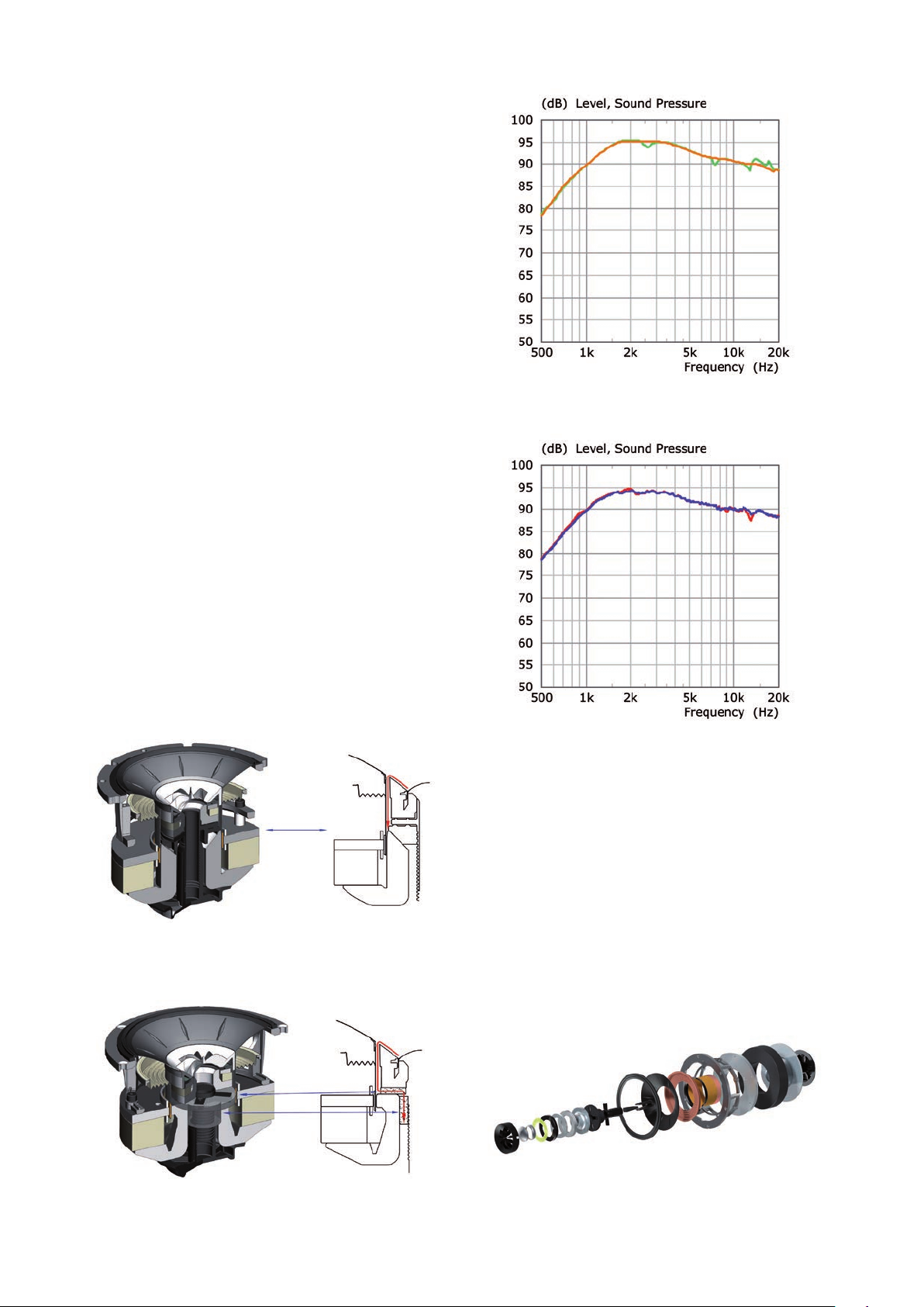
One of the requirements of building this driver combination
is the need to maintain tight tolerances. Some of the gaps
between parts are necessarily small and without robotic
assembly methods it would be impossible to achieve
consistency of performance. There is a place for hand
building, but this is not it.
Filling in the gaps
One of the problems with constructing a combination driver
array like Uni-Q is dealing with the gaps that separate the
constituent parts. There is a narrow channel – an annular
gap – between the moving midrange voice coil and the
static start of the tweeter waveguide. This channel acts as
an organ-pipe-like resonator, and is excited by the tweeter
output. The resonances modify the response of the tweeter,
adding a series of glitches that are not present if the gap is
closed o – simulating a perfectly smooth waveguide.
Obviously, this annular gap is necessary to allow the midrange
cone and voice coil to move, so the solution was to create
a cavity between the midrange and tweeter magnets to
which this annular gap connected. Adding damping to this
newly-created cavity was found to be eective in taming
the resonances in the annular gap and the removal of
the response glitches was immediately apparent as an
improvement in detail clarity.
Figure 15
Simulation of tweeter response
— In perfect waveguide — With open gap
Uni-Q array with no gap between HF and MF magnets
Figure 13
Figure 16
Actual tweeter response
— Original — With cavity damping
Midrange
Cone and surround
The cone is formed from a magnesium/aluminium alloy. Like
the front skin of the bass driver, it serves to provide the
necessary stiness to give pure pistonic motion over the
driver’s working range. The stiness is increased by the radial
embossing in the cone prole, but nevertheless it is prone
to high-Q breakup in the frequency range covered by the
tweeter.
Uni-Q array with opened cavity between HF and MF magnets and damping added
Figure 14
Figure 17
Uni-Q drive exploded view
13
Page 14
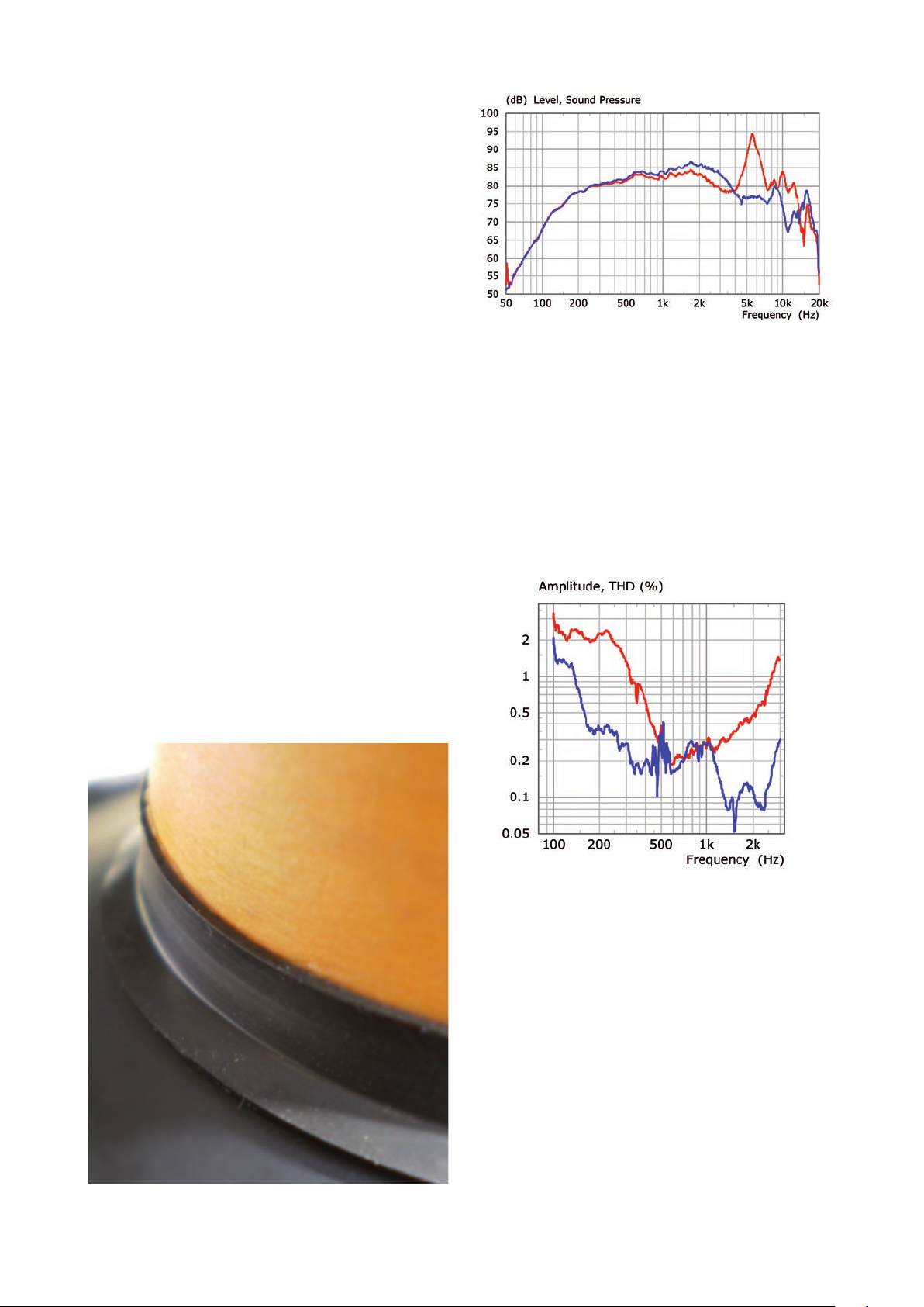
The KEF Blade uses nodal drive (as described on page 11,
where the technique is used on the bass drivers) to tame
these resonances. But that technique, when applied to a
Uni-Q array, cannot use an intermediate cone and instead
requires an expensive large diameter voice coil which was
not appropriate to the R Series.
Instead, there is a lossy interface where the voice coil joins
the cone. This interface serves to decouple the drive at high
frequencies. The high-Q resonances are tamed to the extent
that they may be properly attenuated by the crossover and
not break through the tweeter output.
Response of midrange driver measured without crossover in 2π bae
Figure 19
— without interface — with interface
Figure 19 illustrates the improvement in the unit’s response
as a result of using the lossy interface.
The surround is particularly problematic. It has to allow
the cone to move freely, but it is also a critical part of the
tweeter waveguide. Surrounds also tend to break into
complex vibrational behaviour at higher frequencies, often
moving in the opposite direction to the cone. The so-called
“surround dip” in a driver’s response is quite common.
The new R Series driver features an improved surround
geometry, achieved through extensive computer simulation,
optimisation and practical experimentation. It allows greater
movement of the cone and gives a smoother response for
both midrange and tweeter.
Magnet system
The design of the magnet system follows that of the bass
drivers. alongside the addition of aluminium de-modulation
rings. The reduction in harmonic distortion as a result of
the new magnet system and improved surround geometry
is shown in gure 20.
lossy interface between voice coil and midrange cone
Figure 18
Midrange driver distortion (1m, 5.6V RMS)
Figure 20
— 2011 R Series — 2018 R Series
Tweeter
Diaphragm assembly
The dome diaphragm itself is aluminium. More exotic
materials – diamond and beryllium for example – are
sometimes used in an eort to increase stiness and push the
pistonic region of the tweeter to the limits of human hearing.
But this can be done with aluminium at far lower cost,
providing some ingenuity is used in designing how the dome
is constructed.
14
Page 15
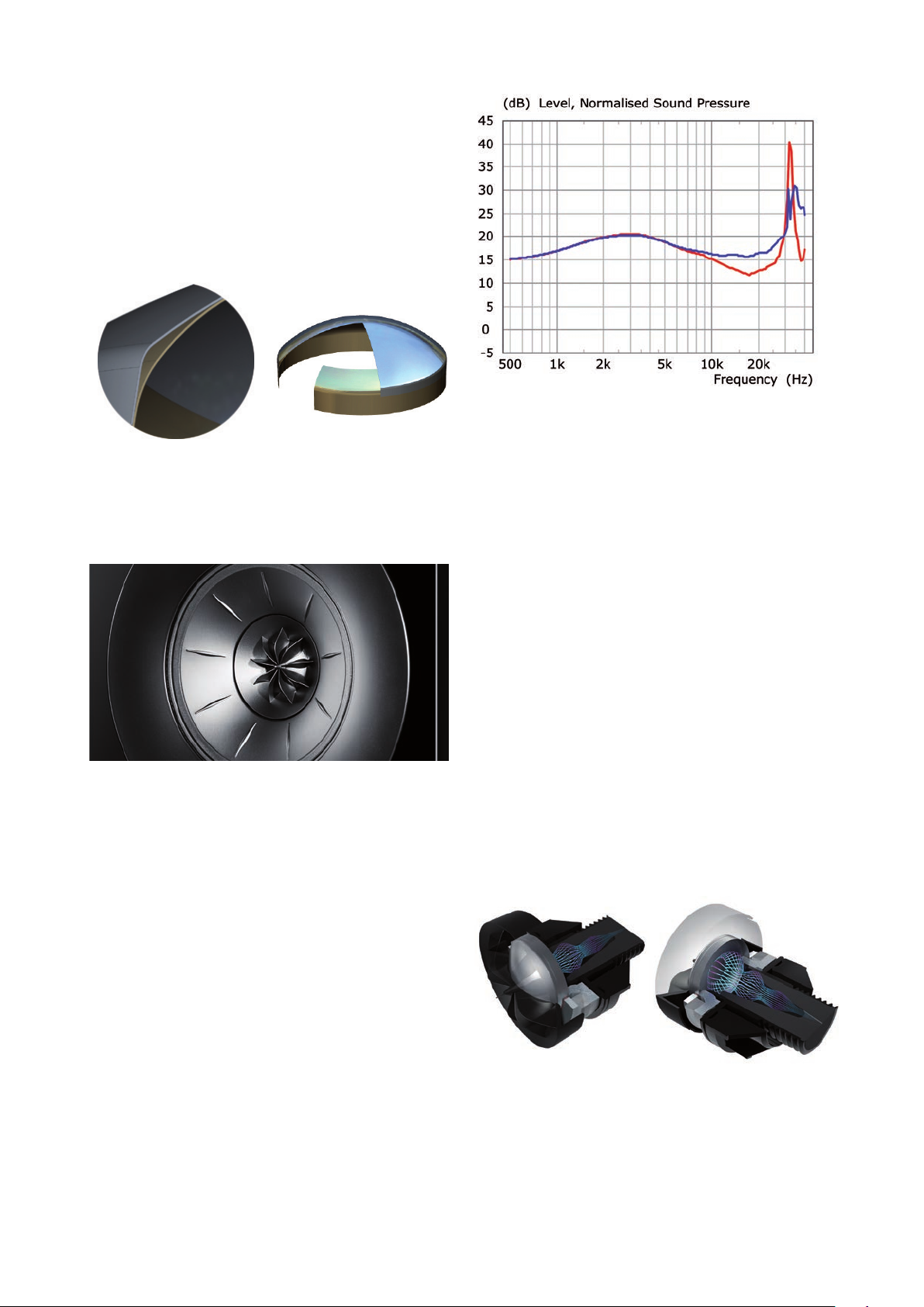
The optimum dome shape for waveguide loading is a
spherical cross-section, but the optimal shape for stiness
is an elliptical cross-section. Both were combined into the
patented KEF Stiened Dome. An elliptical dome attaches
to the voice coil former and the centre is removed. This is
capped by a spherical dome and a very sti triangular section
is formed where the two parts join.
Figure 21
3D CAD sectional views of the tweeter dome and extended former
that meet to form a triangular stiening member at the dome edge.
Tangerine waveguide
Figure 23
Simulated response of tweeter
— without tangerine waveguide — with tangerine waveguide
Rear loading
Like any drive unit, the tweeter radiates as much energy
backwards as it does forwards. Not only does this energy
have to be absorbed, but there must be sucient volume
behind the dome to prevent a build-up of excessive pressure.
This pressure can impair the suspension of the dome and
cause displacement of the ferrouid that sits in the magnet
gap to cool the voice coil.
Figure 22 Tangerine waveguide
The interface between the radiating dome of the tweeter and
the waveguide formed by the midrange dome is extremely
critical. Ideally, the diaphragm should be a pulsating dome,
which would involve the radius of curvature changing. This is
not possible and the motion is in the same direction all over
the surface of the dome. To compensate for this non-ideal
situation and taking a leaf out of the design of pressure drivers,
the Tangerine Waveguide was developed to restore correct
coupling between the dome and the whole waveguide.
The improved coupling at high frequencies above 5kHz
brings with it a useful increase in sensitivity and a reduction in
the height of the rst resonance peak, illustrated by gure 23.
To that end, the dome vents through the centre pole of
the magnet system to a cavity lled with absorbent wadding.
The cavity is tapered to that, when the wadding is inserted,
it becomes more dense towards the rear of the cavity,
gradually increasing absorption.
All the rearward energy is absorbed and cannot re-radiate
through the dome after being reected at the back of
the cavity.
Figure 24
Front and rear view cross sections of tweeter showing rear loading
15
Page 16
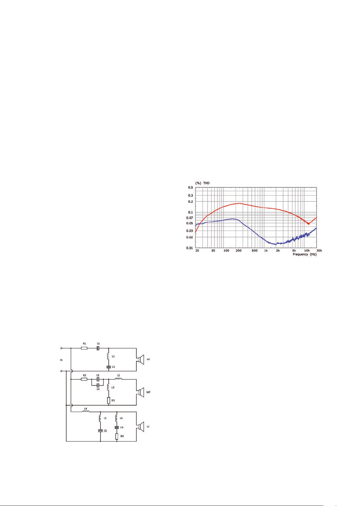
Crossovers
All 3-way crossovers, which covers all bar the 2-way Atmos®
enabled R8a, follow the same general format shown in gure
25.
Each system in the range has been carefully voiced using a
wide variety of musical genres to ensure that no articial
enhancement is introduced.
All cored inductors in the new series crossovers use a
laminated core material that substantially lowers distortion
compared to the outgoing series, as shown in gure 27.
Mention should be made regarding the two parallel
capacitors C3 and C4. The total value is large and low-loss
types would be prohibitively expensive, so the bulk of the
value is made up of an electrolytic type and around 10% of
the total value is a polypropylene type, wired in parallel - the
so-called bypass conguration.
All crossovers have a reduced component count. This has
been made possible due to the decoupler in the Uni-Q
midrange as well as the improved tweeter, both of which
have inherently smoother responses and require less
correction from the crossover. The series resistors in the
MF and HF sections are merely to change the output level of
these drivers to match that of the bass drivers.
The HF section features a tuned circuit (L1/C2) in parallel
with the driver. This tuned to the fundamental resonance
frequency of the driver and allows the series capacitor to
have the correct attenuation. Without it, there would be
excessive movement of the diaphragm and an unwanted
hump in the response.
There are two tuned circuits in the LF section. One (L6/
C6/R4) is tuned to the upper peak of the reex impedance,
and prevents the system impedance falling too low should
the 2nd-order low-pass formed by L4 and C5 be allowed
to interact with it. The inductor L5 is small and tunes with
C5 to attenuate a residual high Q resonance in the driver
response to prevent it colouring the overall sound.
This conguration delivers almost the same low loss and
quality that would be achieved by having the full value solely
supplied by one or more polypropylene capacitors wired in
parallel, but at a much lower cost.
Figure 26
Inductor distortion at 100W
— 2011 R Series — 2018 R Series
General schematic of R Series 3-way crossovers
Figure 25
16
Page 17
17
Page 18
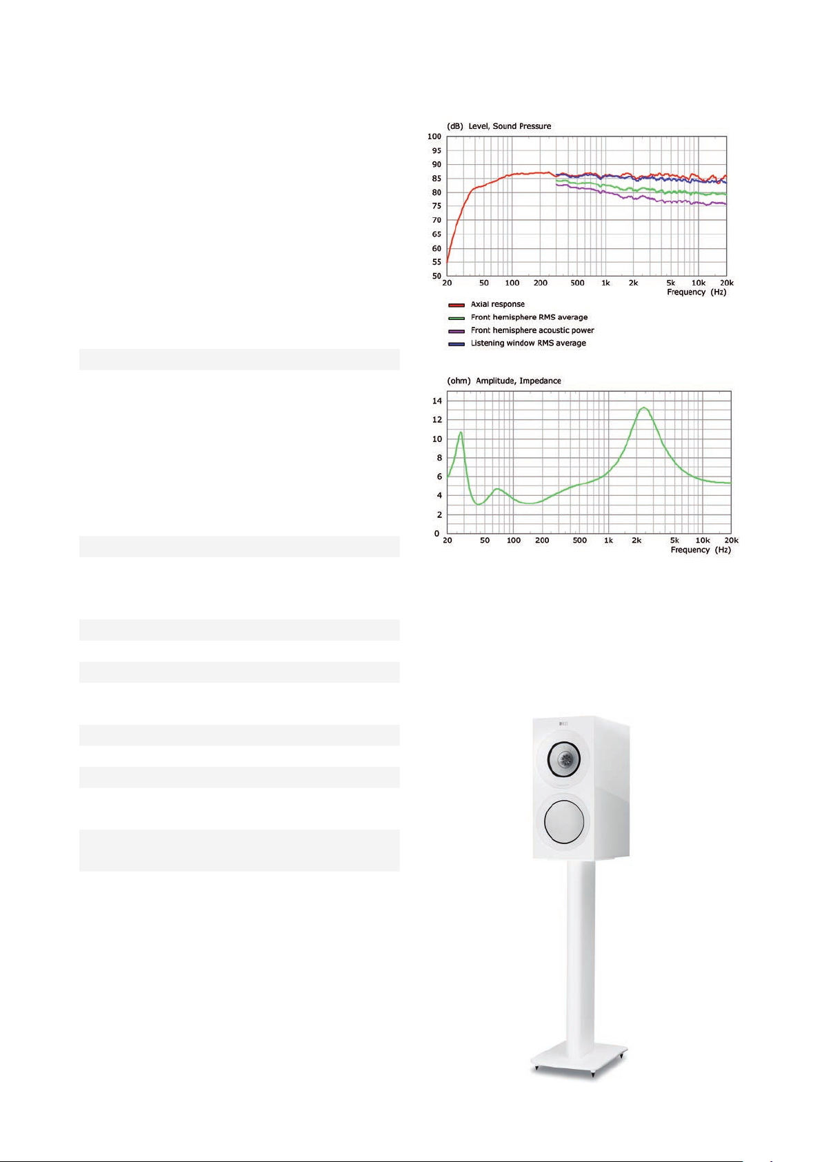
Model Range
R3
Description
This is the smallest of the ‘regular’ loudspeakers in the range,
being a compact 3-way stand-mount model. It is suited to
the smaller room or closer listening, where less power is
required to reach realistic sound levels.
Technical Specications
Design Three-way bass reex
Drive units Uni-Q Driver Array:
HF: 25mm (1in.) vented
aluminium dome
MF: 125mm (5in.)
aluminium cone
Bass Driver:
LF: 165mm (6.5in.)
hybrid aluminium
Crossover frequency 400Hz, 2.9kHz
Frequency range (-6dB)
Typical in-room bass
response (-6dB)
Frequency response (±3dB) 58Hz - 28kHz
Harmonic distorition <0.3% 130Hz - 20kHz
Maximum output 110dB
Amplier power
(recommended)
Nominal impedance 8Ω (min.3.2Ω)
Sensitivity (2.83V/1m) 87dB
Weight* 13.5 kg (29.8 lbs.)
Dimension (H x W x D)
with terminal*
Finishes Black Gloss / White Gloss
38Hz - 50kHz
30Hz
15 - 180W
422.2 x 199.6 x 335.5 mm
(16.6 x 7.9 x 13.2 in.)
/ Walnut
* Measurement per unit
18
Page 19
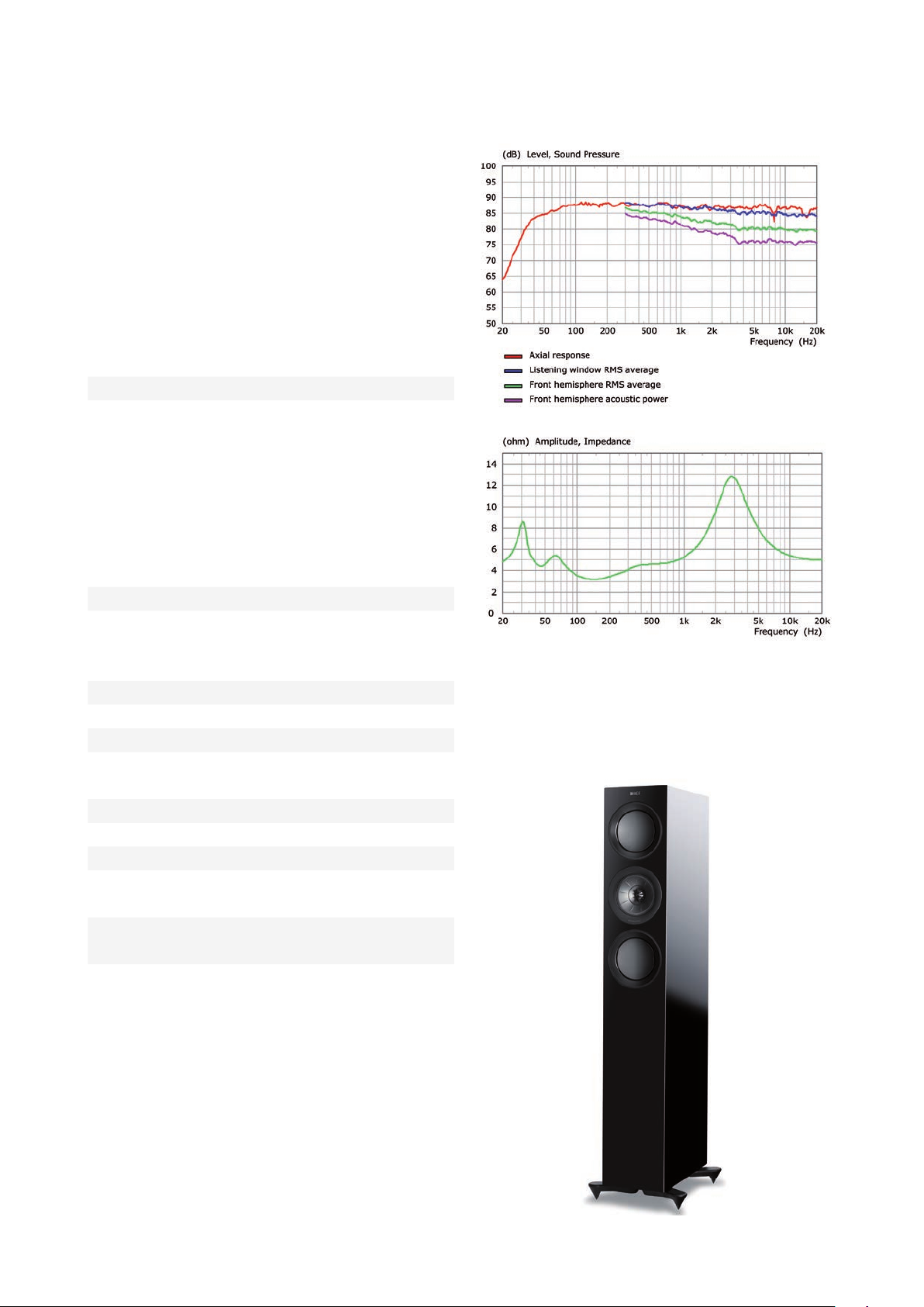
R5
Description
This is the smallest of the three oor-standers in the range.
It’s twin 130mm diameter bass drivers are positioned each
side of the Uni-Q array in d’Appolito conguration, to
preserve an eective point source delivery throughout the
whole frequency range.
Technical Specications
Design Three-way bass reex
Drive units Uni-Q Driver Array:
HF: 25mm (1in.) vented
aluminium dome
MF: 125mm (5in.) aluminium
cone
Bass Driver:
LF: 2 x 130mm (5.25in.)
hybrid aluminium
Crossover frequency 400Hz, 2.9kHz
Frequency range (-6dB)
Typical in-room bass
response (-6dB)
Frequency response (±3dB) 52Hz - 28kHz
Harmonic distorition <0.3% 120Hz - 20kHz
Maximum output 110dB
Amplier power
(recommended)
Nominal impedance 8Ω (min.3.2Ω)
Sensitivity (2.83V/1m) 87dB
Weight* 27.3 kg (60.2 lbs.)
Dimension (H x W x D)
with terminal*
Dimension (H x W x D)
with terminal with Plinth*
Finishes Black Gloss / White Gloss /
38Hz - 50kHz
29Hz
15 - 200W
1025 x 175 x 343.5 mm
(40.4 x 6.9 x 13.5 in.)
1071.4 x 271.6 x 343.5 mm
(42.2 x 10.7 x 13.5 in.)
Walnut
* Measurement per unit
19
Page 20
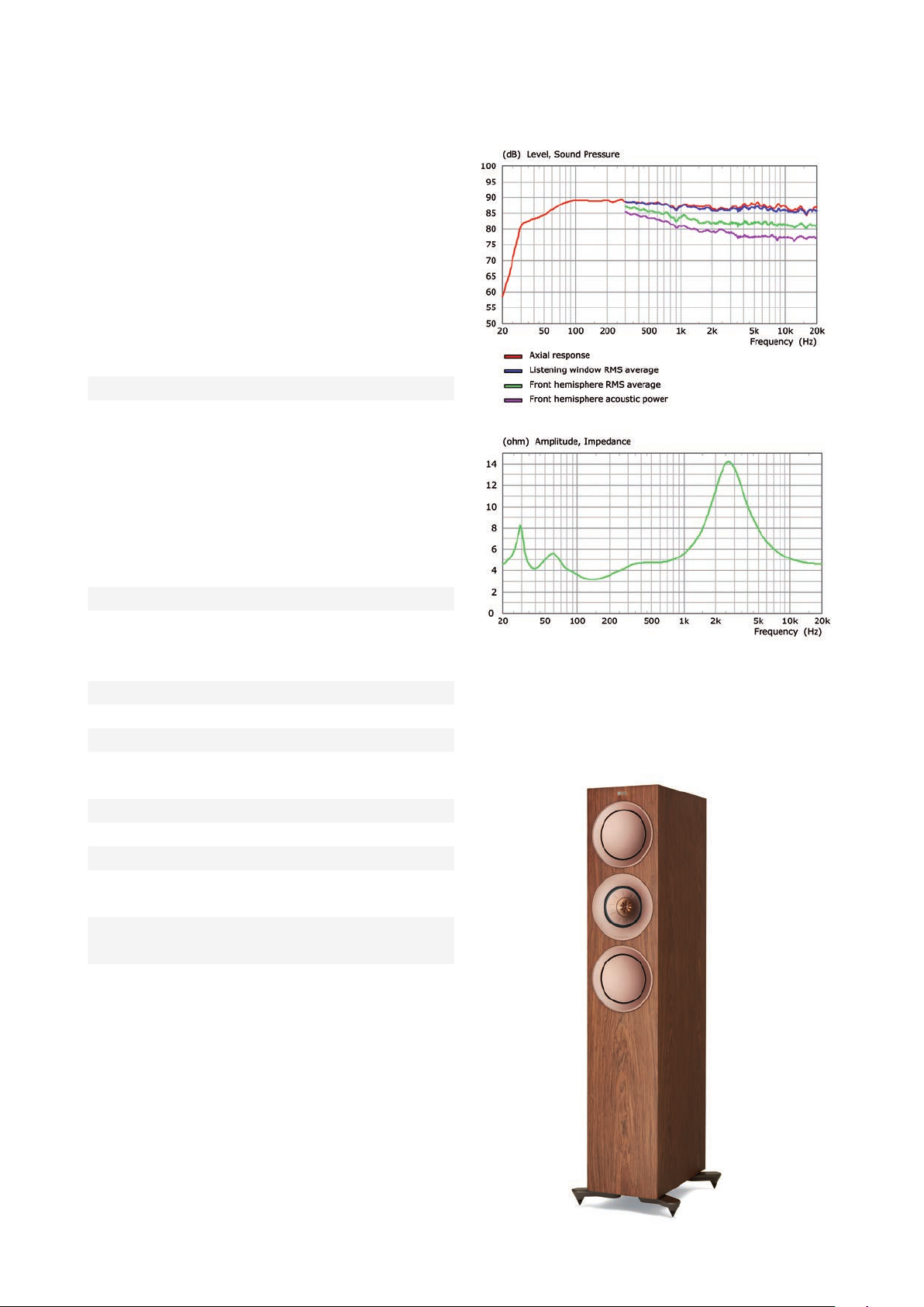
R7
Description
Like the R5, this is a oor-standing loudspeaker featuring twin
bass drivers positioned above and below the Uni-Q array.
However, the larger diameter of the bass drivers enables a
higher sound level to be delivered and the larger cabinet
aords a greater bass extension.
Technical Specications
Design Three-way bass reex
Drive units Uni-Q Driver Array:
HF: 25mm (1in.) vented
aluminium dome
MF: 125mm (5in.) aluminium
cone
Bass Driver:
LF: 2 x 165mm (6.5in.)
hybrid aluminium
Crossover frequency 400Hz, 2.9kHz
Frequency range (-6dB)
Typical in-room bass
response (-6dB)
Frequency response (±3dB) 48Hz - 28kHz
Harmonic distorition <0.3% 120Hz - 20kHz
Maximum output 111dB
Amplier power
(recommended)
Nominal impedance 8Ω (min.3.2Ω)
Sensitivity (2.83V/1m) 88dB
Weight* 31.4 kg (69.2 lbs.)
Dimension (H x W x D)
with terminal*
Dimension (H x W x D)
with terminal with Plinth*
Finishes Black Gloss / White Gloss /
33Hz - 50kHz
27Hz
15 - 250W
1062 x 200 x 383.5 mm
(41.8 x 7.9 x 15.1 in.)
1108.9 x 310.6 x 383.5 mm
(43.7 x 12.2 x 15.1 in.)
Walnut
* Measurement per unit
20
Page 21
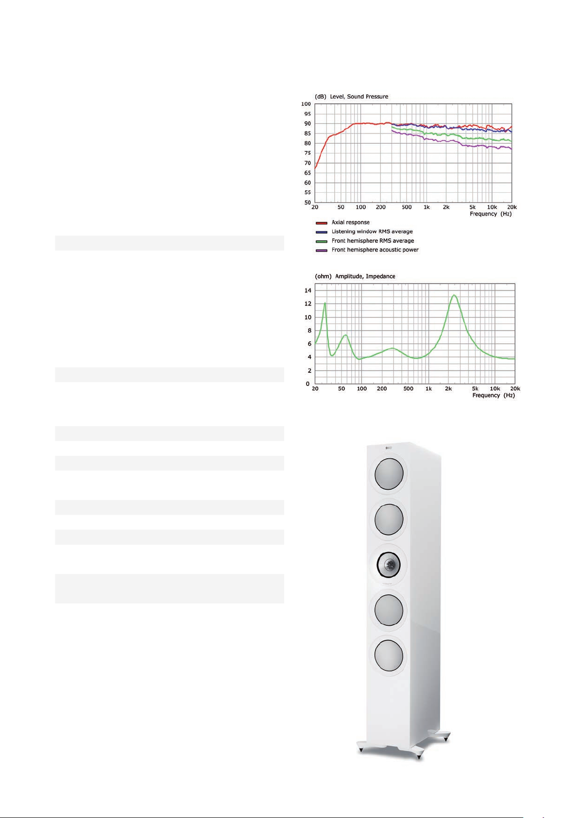
R11
Description
This, the largest loudspeaker in the range, features four
165mm (6½ inch) diameter bass drivers, enabling a enough
sound level output to drive large rooms without distress.
The large cabinet aords the most extended bass response.
Technical Specications
Design Three-way bass reex
Drive units Uni-Q Driver Array:
HF: 25mm (1in.) vented
aluminium dome
MF: 125mm (5in.) aluminium
cone
Bass Driver:
LF: 4 x 165mm (6.5in.)
hybrid aluminium
Crossover frequency 400Hz, 2.9kHz
Frequency range (-6dB)
Typical in-room bass
response (-6dB)
Frequency response (±3dB) 46Hz - 28kHz
Harmonic distorition <0.3% 120Hz - 20kHz
Maximum output 113dB
Amplier power
(recommended)
Nominal impedance 8Ω (min.3.2Ω)
Sensitivity (2.83V/1m) 90dB
Weight* 37.7 kg (83.1 lbs.)
Dimension (H x W x D)
with terminal*
Dimension (H x W x D)
with terminal with Plinth*
Finishes Black Gloss / White Gloss /
30Hz - 50kHz
26Hz
15 - 300W
1249 x 200 x 383.5 mm
(49.2 x 7.9 x 15.1 in.)
1295.5 x 310.6 x 383.5 mm
(51 x 12.2 x 15.1 in.)
Walnut
* Measurement per unit
21
Page 22
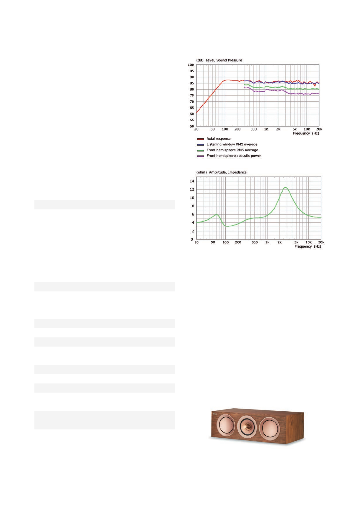
R2c
Description
This is the rst of two special application loudspeakers. It’s
a dedicated centre-channel model and, like the R5 features
two 130mm (5¼ inch) diameter bass drivers each side of
a centrally placed Uni-Q array. Normally, the horizontally
disposed drivers of centre-channel loudspeakers suer a
restricted horizontal dispersion in the crossover region
between midrange and tweeter, or throughout the midrange
band if two drivers are used to cover that frequency range.
However, the point-source Uni-Q array avoids this and oers
better horizontal dispersion than any other horizontally
disposed conguration.
Technical Specications
Design Three-way closed box
Drive units Uni-Q Driver Array:
HF: 25mm (1in.) vented
aluminium dome
MF: 125mm (5in.)
aluminium cone
Bass Driver:
LF: 2 x 130mm (5.25in.)
hybrid aluminium
Crossover frequency 400Hz, 2.9kHz
Frequency range (-6dB)
Typical in-room bass
response (-6dB)
Frequency response (±3dB) 74Hz - 28kHz
Harmonic distorition <0.3% 120Hz - 20kHz
Maximum output 110dB
Amplier power
(recommended)
Nominal impedance 8Ω (min.3.2Ω)
Sensitivity (2.83V/1m) 87dB
Weight* 16.9 kg (37.3 lbs.)
Dimension (H x W x D)
with terminal*
Finishes Black Gloss / White Gloss
64Hz - 50kHz
49Hz
15 - 200W
175 x 550 x 308.5 mm
(6.9 x 21.7 x 12.1 in.)
/ Walnut
* Measurement per unit
22
Page 23
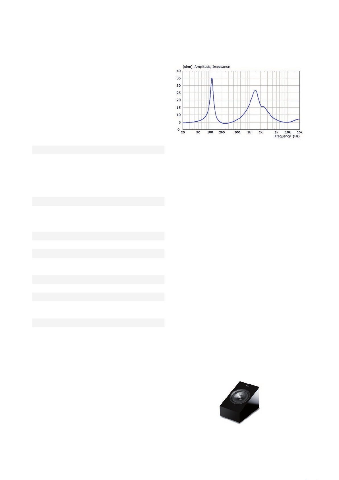
R8a
Description
This compact model is the only 2-way loudspeaker in the
range. It features a single Uni-Q array, this time having a bass/
midrange driver surrounding the centrally placed tweeter
unit. It’s angled front bae makes it the perfect solution for
either a wall-mounted surround loudspeaker or a speaker-
top-mounted Dolby Atmos® module.
Technical Specications
Design Two-way closed Box
Drive units Uni-Q Driver Array:
HF: 25mm (1in.) vented
aluminium dome
MF/LF: 130mm (5.25in.)
aluminium cone
Crossover frequency 2 kHz
Frequency range (-6dB)
Typical in-room bass
response (-6dB)
Frequency response (±3dB) 105Hz - 18.5kHz
Harmonic distorition <0.3% 200Hz - 20kHz
Maximum output 106dB
Amplier power
(recommended)
Nominal impedance 8Ω (min.4.2Ω)
Sensitivity (2.83V/1m) 86dB
Weight* 4.45 kg (9.8 lbs.)
Dimension (H x W x D)
with terminal*
Finishes Black Gloss / White Gloss
96Hz - 19.5kHz
-
25 - 150W
173.8 x 174.6 x 259 mm
(6.8 x 6.9 x 10.2 in.)
* Measurement per unit
23
Page 24

Summary
References
The R Series sits immediately below the Reference Series
and borrows much of that range’s technological attributes.
It follows our belief that a great sounding loudspeaker is the
result of solid, careful and eective engineering. This involves
utilising every computer simulation and measuring technique
available, backed up by practical experimentation and
verication.
But loudspeakers, like any other component of the
reproduction chain, are there to communicate more than
mere measurements and specications. As Raymond
Cooke realised from the start, emotion and involvement
are also part of what must be delivered to the listener. For
that reason, engineers and non-engineers alike audition
prototypes at every stage of development to make sure
that the engineering is relevant and improves the overall
performance.
More than that, it is the same team that guides every KEF
product through its development, with the result that there
is a consistency of what constitutes quality throughout
the company’s portfolio. The products deliver outstanding
performance whatever the musical genre and regardless
of whether the programme is 2-channel or multi-channel
based.
The R Series incorporates many technologies that were
pioneered by KEF - the Uni-Q point source array is probably
the best-known and certainly one of the most eective
of these. But this paper illustrates how every aspect of
loudspeaker performance has been assessed and taken to the
limit, within the imposed budgetary constraints, sometimes
involving a new and dierent way of addressing the problem.
O J Pedersen, S Bech and K Rasmussen, Final Report on
Activities of Eureka Project ARCHIMEDES. Univ., 1995.
L R Fincham, A Jones and R H Small, “The Inuence of
Room Acoustics on Reproduced Sound, Part 2: Design of
Wideband Coincident-Source Loudspeakers”, in The 87th
Convention of the AES, 1989.
“The Reference (white paper)”, KEF R&D, May-2014.
K Kessler, D A Watson and M Cooke, “KEF 50 Years of
Innovation in Sound” – A Limited Edition Book, GP Acoustics
International Limited, Maidstone, UK, 2011.
M Dodd and J Oclee-Brown, “A New Methodology for the
Acoustic Design of Compression Driver Phase Plugs with
Radial Channels”, presented at the Audio Engineering Society
Convention 125, 2008.
M Dodd, “Optimum Diaphragm and Waveguide Geometry
for Coincident source Drive Units”, presented at the Audio
Engineering Society Convention 121, 2006.
M Dodd and J Oclee-Brown, “Design of a Coincident Source
Driver Array with a Radial Channel Phase-Plug and Novel
Rigid Body Diaphragms”, presented at the Audio Engineering
Society Convention 127, 2009.
M Dodd, W Klippel, and J Oclee-Brown, “Voice Coil
Impedance as a Function of Frequency and Displacement”,
presented at the Audio Engineering Society Convention 117,
2004.
Some of the techniques described here are dealt with in
greater detail in the KEF Reference Series white paper and
the interested reader is urged to peruse that in addition to
the other publications featured in the list of references on
the next page.
Acknowledgements
The KEF logo and Uni-Q is are registered trademarks of GP
Acoustics (UK) Ltd. Dolby and Atmos are trademarks of
Dolby Laboratories.
L L Beranek, “Acoustics”, McGraw-Hill, 1954 revised 1986
G Perkins, “Modelling loudspeaker cabinet diraction”,
presented at the IOA Reproduced Sound conference, 2014.
M Dodd, “The Development of the KEF LS50, a Compact
Two-way Loudspeaker System”, presented at the Audio
Engineering Society Conference: 51st International
Conference: Loudspeakers and Headphones, 2013.
24
 Loading...