

Page 1

Industrivej 3-9
DK 9460 Brovst
Tel. +45 9823 6266
Fax. +45 9823 6144
25.04.12
KEF-MOTOR A/S
Instruction Manual
PSD 5 – BO 50/5 – POD 5 - PODA 5
Industrial Grinders
Page 2

1
Introduction
You can connect your dual grinder in many ways. This manual includes the following
options for use of your dual grinder:
PSD 5 for grinding,
BO 50/5 for grinding and belt grinding
POD 5 for polishing
PODA 5 for polishing and deburring
EU declaration of conformity
hereby declares that
KEF Double Ended Grinder PSD 5, BO 50-5, POD 5 are manufactured in accordance
with the provisions of the COUNCIL DIRECTIVE of 17. May 2006 (2006/42/EC) – The
Machinery Directive (order no. 561 of 25 June 1994 with subsequent amendments)
Also on accordance with:
The council directive of 19 February 1973 (73/23/EEC) – The Low Voltage Directive
– with later amendments (order no. 797 of 30 August 1994)
The council directive of 3 May 1989 (89/336/EEC) – The EMC Directive – with later
amendments (order no. 796 of 5 December 1991 with subsequent amendments)
KEF-MOTOR A/S
Industrivej 3-9
DK-9460 Brovst
Denmark
www.scantool-group.com
Tel.: +45 98 23 62 66
Fax: +45 98 23 61 44
Page 3

2
Table of contents
1 TRANSPORT & HANDLING 3
1.1 TRANSPORT 3
1.2 HANDLING 3
1.3 PLACING 3
2 DIRECTIONS FOR USE 4
2.1 OPERATION 4
2.2 SAFETY RULES FOR STATIONARY POWER TOOLS. 4
2.3 MAINTENANCE 6
3 BELT ARM 7
3.1 ASSEMBLY AND MOUNTING OF BELT ARM 7
3.2 CHANGING OF GRINDING BELT 8
3.3 MAINTENANCE OF BELT ARM 9
3.4 USE OF BELT ARM 9
4 VFCB-COMPLETE EXHAUST UNIT 10
4.1 ASSEMBLING AND MOUNTING OF VFCB – COMPLETE EXHAUST UNIT 10
4.2 MAINTENANCE OF VFCB-EXHAUST UNIT 10
5 POLISHING MACHINE 13
5.1 ADJUSTMENT THE POLISHING MACHINE. 13
6 DEBURRER 11
6.1 ASSEMBLING AND MOUNTING OF DEBURRER 11
6.2 CHANGING OF DEBURRER/STEEL BRUSH 11
6.3 MAINTENANCE OF DEBURRER/STEEL BRUSH 12
6.4 USE OF DEBURRER 12
7 SPARE PARTS 14
7.1 MACHINE LINE UP OF PSD 5 14
7.2 PSD 5 BASIC MODEL 15
7.3 PSD 5 COVER 16
7.4 PSD 5 BELT ARM 17
7.5 VFCB-EXHAUST SYSTEM FOR PSD 5 19
7.6 POD 5 W/SPINDLE 23
7.7 DEBURRING COVER FOR PODA 5 21
7.8 24
8 TECHNICAL DATA 24
8.1 TECHNICAL SPECIFICATIONS 24
8.2 DIMENSIONS 24
8.3 WIRING DIAGRAM 25
8.4 DISA SWITCH W/EMERGENCY STOP 26
8.5 8.5 PSD 5 CONNECTED TO EX16 DUST EXTRACTION 27
8.6 GUARANTEE 28
Page 4
3
1 Transport & handling
1.1 Transport
PSD 5 Industrial belt grinder and others are delivered on a pallet packed in protective
wrapping.
1.2 Handling
The machines can easily be transported on the pallet on which they are delivered. If the
machine is delivered on a pedestal you must insure that the pedestal is secured to the
pallet.
1.3 Placing
Mounting of the machine must take place on a firm level ground. It must be fastened to the
ground by means of the four fittings which are used to fasten the machine to the pallet. It is
provided with no-volt release protection switch and connected for the wanted voltage. The
electrical connection must be performed by an authorized electrician, and it is important to
control that the motor (and the exhaust unit) have the correct direction or rotation (please
see the arrow on the motor).
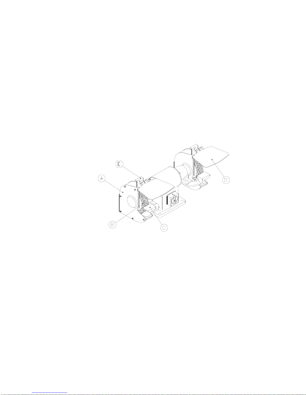
Fig.: 1.1
Before use you must control that the outer cover (A) (se fig.: 1.1) is solidly mounted on the
inner cover. The outer cover must stay mounted during use and should only be dismounted
during change of grinding wheel. The grinding wheel (B) must be able to rotate freely
without being loose. The tool rest (C) must be adjusted to a distance of approximately 2 mm
from the grinding wheel.
The eye shield (D) must be clean and adjusted into the right position and the spark arrester
(E) must also be adjusted to a distance of approximately 5 mm from the grinding wheel and
slightly fastened.
The first time you start the belt grinder please let it run at max speed without using it for 5
minutes. Make sure to stay in a safe distance during the machine start-up.
Page 5

4
2 Directions for use
2.1 Operation
After adjustment and connection the machine is ready for use. The grinding kan take place
by the contact wheel (E) or on the surface grinding table by opening the cover (H). When
you start grinding please start by letting the material touch the grinding wheel lightly and
thereby avoid pressuring the grinding wheel to prolonge the lifetime of it. The lifetime of a
grinding belt is also prolonged if you start with a light pressure. Please make sure not to
overload the motor. Let it run at max speed before start grinding. Grind at max speed and if
possible have the material tightened in clamps as it is safer than holding the material in
your hands. Avoid grinding on the side of the grinding wheel unless you are using a cup
wheel. Do not stop the grinding wheel by pushing any material against it but let it stop by
itself. It is very important to keep the working area well lighted.
2.2 Safety rules for stationary power tools.
Follow them to achieve best results and full benefit from your new machine.
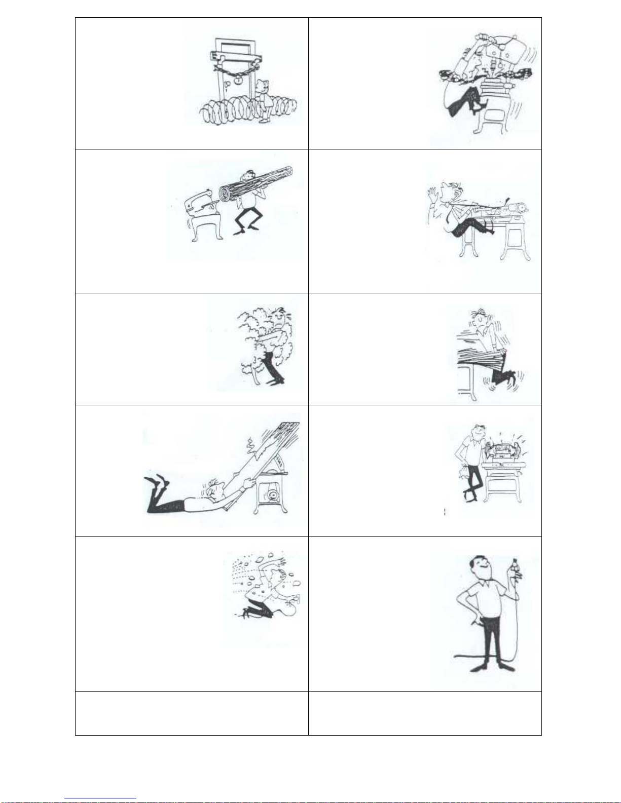
The good craftsman respects
the tools with which he works.
He knows they represent years
of constantly improved design.
He also knows that they are
dangerous if misused.
The safety rules are based on
approved practices in industrial
and home shops.
1. Know your power
tool. Read the
owner’s manual
carefully. Learn its
applications and
limitations, as well
as the specific
potential hazards
peculiar to this tool.
2. Keep guard in place
and in working order.
3. Ground all tools. If tool is equipped with threeprong plug, it should be plugged into a three-hole
electrical receptacle. If an adapter is used to
accomodate a twoprong receptacle, the
adapter wire must be
attached to a known
ground. Never
remove the third
prong.
4. Remove adjusting keys
and wrenches. Form
habit of checking to see
that keys and adjusting
wrenches is removed
before turning it on.
5. Cluttered areas and benches invite accidents.
6. Avoid dangerous
environment. Don’t use
power tools in damp or wet
locations or expose them to
rain. Keep your work area
well lighted.
6. Keep children away.
All visitors should be
kept in a safe distance
from work area.
Page 6
5
8. Make workshop
kidproof with
padlocks, master
switches, or by
removing starter keys.
9. Don’t force tool. It will
do the job better and be
safer at the rate for
which it was designed.
.
10. Use right tool.
Don’t force tool or
attachment to do
a job it was not
designed for.
11. Wear proper apparel. Wear no loose clothing,
gloves, neckties, rings,
bracelets, or other
jewelry which may get
caught in moving parts.
Non-slip footwear is
recommended. Wear
protective hair covering
to contain long hair.
12. Always use safety
glasses. Also use face or
dust mask if cutting
operation is dusty.
Everyday eyeglasses only
have impact resistant
lenses. They are NOT
safety glasses.
13. Secure works. Use
clamps or vise to hold
works, when pratical. It’s
safer than using your
hands and it frees both
hands to operate tool.
14. Don’t
overreach.
Keep proper
footing and
balance at
all times.
15. Maintain tools with care. Keep tools sharp and
clean for best and safest
performance. Follow
instructions for lubricating
and changing accessories.
16. Disconnect tools before
servicing and when changing
accessories such as grinding
wheels, polishing mops,
grinding belts, blades, bits,
cutters, etc. Never leave a
running maschine, wait till the
Machine has stopped. If parts
of the machine are out of order
the Machine shold not be used
befour it has been repaired.
17. Reduce the risk of
unintentional starting.
Make sure switch is in off
position before plugging
in.
18. Use recommended accessories. Consult owner’s
manual for recommended accessories. Use of
improper accessories may cause risk of injury to
persons.
19. Never work in a way that can hurt you. Do not
stand in a bent position. Stand straight. Alkohol and
other drugs are not to be taken while working with
the machine.
Page 7

6
2.3 Maintenance
Keep the machine in a dry place so the grinding wheels or belts will not risk getting any
damp or rain.
The grinding wheel will often get uneven because of use and therefore we recommend that
you level the grinding wheel off frequently. When the grinding wheel is worn more than 25%
we recommend that you change to a new wheel. An uneven grinding wheel causes
vibrations which with time will damage the bearings in the machine. Damaged tool rests,
eye shields and covers must be replaced to avoid personal damage.
When to change the grinding wheel please dismount the spark arrester (A) (see fig.: 2.1),
then dismount the outer cover (B). The reverse nut (C) and the outer flange is to be
unscrewed, now the outer flange and the grinding wheel can be dismounted. The new
grinding wheel is not allowed to exceed the measures shown on the sign on the machine. It
is also very important that the hole dimension is correct.
The grinding wheels are provided with labels placed around the holes on both sides of the
grinding wheel. If these labels are missing or damaged they must be replaced by new ones
of the same dimension.
The new grinding wheel is to be mounted between the two flanges (D) and the reverse nut
(C) screwed on and fastened. The reverse nut (C) is to be fastened so tightly that it can
hold the grinding wheel tight but on the other hand it is not to be tightened too much as it
can cause unwanted stress in the grinding wheel.
Fig.: 2.1
Page 8

7
3 Belt Arm
3.1 Assembly and mounting of belt arm
If the grinding machine is mounted with a grinder cover or a deburrer cover these must be
removed completely before mounting the belt arm.
Mount the telescopearm (A) to the cover (B) by using the fitting for the telescope arm (C)
and mounting the cover (B) by putting a screw through the side plate into the holder for the
telescopearm (D). The topwheel (E) must be inside the cover (B).
Fig.: 3.1
The fitting for the telescopearm (C) is not alloved to be fastened harder than it is
still possible to adjust the direction of the grinding belt.
The belt arm can be tilted to the wanted inclination. After this the holder for the
telescopearm (D) is fastened by tightening the two screws placed in the ring on the
holder. The flanges, contact wheel and the reserve nut are now put in (pls. see the
drawing of belt arm for order). Please make sure that the top wheel (E) and the
contact wheel run parallelly. The position of the contact wheel can be adjusted with
the distance rings attached.
The topwheel (E) can be loosened and adjusted so that it fits the wanted grinding
belt lenght. The same way you can tighten the grinding belt.
Page 9
8
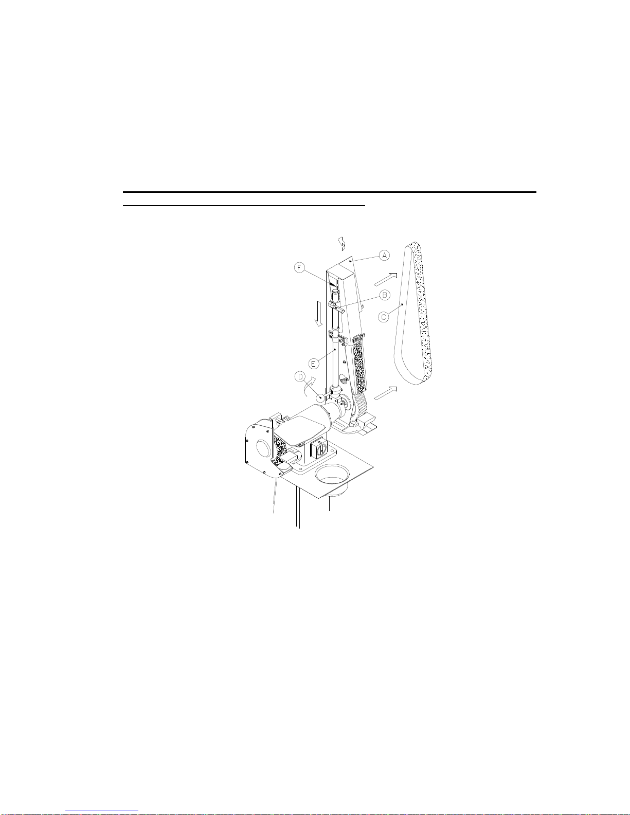
3.2 Changing of grinding belt
When the grinding belt is worn out it must be replaced which is done the following
way: The top plate (A) (se fig.: 3.2) on the cover is opened and the handle (B) is
pulled down. This way the pressure on the grinding belt will be lowered (C), so that
it can be dismounted and a new grinding belt can be mounted in reverse order.
Please control that the arrows on the back of the grinding belt run in the same
direction as they point. When the new grinding belt is mounted it is necessary to
adjust by the handle (D) for parallel running. The belt is loosened so that the
telescopearm (E) and top wheel (F) can be turned with until the grinding belt runs
straightly on the contactwheel. After this the handle is fastened (D).
It is only allowed to do this adjustment by pulling the grinding belt with the
hands and NOT with power on the machine.
Fig.: 3.2
There are many kinds of grinding belts so therefore it is very important to choose
the right type of belt. There are many things to consider before choosing the belt:
material to be grinded - grit size - belt material - glue.
In connection to this we can tell you that there are different kinds of contact wheels
with various softnes and shapes for different purposes.
Page 10

9
3.3 Maintenance of belt arm
Empty the spark arrester (A) (see fig.: 3.3) to avoid hot sparks damaging or
deforming grinding belt and contact wheel. If the machine is equipped with VFCBexhaust unit you must control if the suction channels need cleaning. The dust bag
must be emptied when necessary. The contact wheel (B) needs changing if the
edges are too rounded. The belt must be replaced when it is defective. Change the
graphite pad (C) on the belt arm when necessary.
Fig.: 3.3
When changing the contact wheel the grinding belt (D) must be dismounted as
described above. The reverse nut (E) must be dismounted and the flange (F) can
be taken off with the contact wheel (B). The new contact wheel (B) is to be mounted
in reverse order.
3.4 Use of belt arm
Grinding at the belt arm can be done either at the contact wheel or on the grinding
surface. You can also dismount the grinding surface for direct unsupported grinding
on the grinding belt. Let the material touch the grinding belt softly and avoid uneven
grinding as it can damage the grinding belt and overload the motor.
Page 11

10
4 VFCB-complete exhaust unit
4.1 Assembling and mounting of VFCB – complete exhaust unit
The following description of assembling and mounting of VFCB-exhaust unit is valid both if
it is a VFCB-220 or if it is a VFCB-121. The mounting order is exactly the same for both
models.
The guard (A) (see fig.: 5.1) is first mounted on the back of the machine and there after as
shown on the VFCB-motor. Dismount the blindstopper at the back of the machine and
mount the connector (B). Dismount the switch on the machine without dismounting the
wires. Lead the wire (C) through the connector (B) and mount the protection hose (D) on
the connector (B). Mount the wires from the VFCB-exhaust unit on the switch (see wiring
diagram). Mount the switch again. Dismount the blind guards on the cover or the belt arm
and instead mount the guard (E) with exhaust connecting piece, also remember to mount
the cork washer (F). Finally adjust the suction hoses (G) and mount the clip washers (H).
VFCB-exhaust unit must before use be mounted with suction hoses on the suction
connecting piece (I), which then must be connected with central exhaust unit. If the central
exhaust unit has no cyclone, the exhaustion from the VFCB-exhaust unit must be
connected to a cyclone, which then again is connected to the central exhaustion. If there is
no central exhaustion, dust bags (J) can be mounted on the exhaust connecting unit (I).
In case the VFCB-exhaust unit is mounted on the PSD 5 double grinder, the casted pipe
bendings (K) can be used to mount the VFCB-exhaust unit on the grinding machine by what
the guard (A) and the suction hoses (G) with accessories can be left out.
Fig.: 4.1
4.2 Maintenance of VFCB-exhaust unit
Nothing on a VFCB-exhaust unit requires maintenance except that it is necessary to make
sure that the suction hoses are intact and the suction channels are clear.
Page 12

11
5 Deburrer
5.1 Assembling and mounting of deburrer
The deburrer cover is to be assembled in the order shown in fig.: 5.1. The four
screws in the end cover (A) must be unscrewed and the mounting plate (B) is to be
placed on the end cover (A), the four countersinked machine screws M6x20 (C) are
retightened. Now the deburrer cover (D) can be remounted through the two slashes
in the mounting plate (B). The cover can be repudiated back and forth so the steel
brush (G) can be used best possible. The inner flange (F) is put on the shaft with
the steel brush (G) and the outer flange (H). At last the reverse nut (I) is screwed on
the shaft and tightened. Before the lid on the deburrer cover (D) is closed the eye
shield is mounted (J) as shown in fig.: 4.1. If you are not to grind a pipe material
you can dismount the grinding system for pipe grinding (K) and the flat grinding
system beneath can be used instead.
Fig.: 5.1
5.2 Changing of deburrer/steel brush
When the steel brush is worn approximately 10 % it must be replaced by a new brush. This
is easily done by opening the lid on the deburrer cover (D). Here you dismount the reverse
nut (I) and the flange (H) can be taken off with the steel brush. The new steel brush is
mounted in reverse order. Often it will be necessary to adjust the grinding system (K) before
the new steel brush is put in its place.
Page 13

12
5.3 Maintenance of deburrer/steel brush
Nothing on the deburrer/steel brush needs maintenance except that it is necessary to adjust
the grinding system as the steel brush is worn. The eye shield and other accessories must
be replaced immediately if they are damaged.
5.4 Use of deburrer
When the deburrer cover is correctly mounted the grinding system (A) (see fig.: 5.2) needs
adjusting which is done by adjusting the height of the grinding system when the screw (B)
is unscrewed. The distance to the steel brush is adjusted by loosening the handle (C) below
the cover. As mentioned earlier the grinding system for pipe grinding (A) can be dismounted
and the flat grinding surface beneath can be used for grinding of plate or bar material.
This adjustment of the grinding system can only be made when the machine is NOT
plugged.
Fig.: 5.2
Before the deburring is started it is important that the motor is running at max speed and
the deburring must be done at as high speed as possible. If it is possible please hold the
material with clamps as it is safer than holding the material right in your hands.
If the motor is helped at stopping the rotation it can result in overheating and destruction.
The best result will be achieved if the material is softly put towards to steel brush. Avoid
uneven deburring to avoid damaging the steel brush and overloading the motor.
Do not stop the steel brush rotation by pressing a material to it but let it rotate freely until it
stops by itself.
It is very important to have the work space well lighted as well as the Law for Safety and
Health at Work Act demands that there must be an exhaust unit mounted on the deburring
cover. This is easily done by mounting a VFCB-exhaust unit on the machine.
Page 14

13
6 Polishing machine
6.1 Adjustment the polishing machine.
Placing of the machine must take place on a firm and level surface. Now secure the
polishing machine to the work table or the floor by using the four holes in the base used for
mounting the machine to the pallet.
Please wire the machine according to the given voltages stated in this manual and on the
motor sign. Check for correct direction of rotation on the motor. All wiring must be
performec by an authorized electrician.
Fig.: 6.1
Before start operating please check if the polishing discs (A) (see fig.: 6.1) are firmly
secured to the rotor. The polishing disc is mounted when the machine is disconnected. The
polishing disc (A) must rotate freely without being loose.
Checks and adjustments are only to be performed when the machine is disconnected.
Make sure to be in a safe distance from the machine while it is running for the first time.
Page 15

14
7 Spare parts
In this chapter there are split drawings and matching spare parts lists.
7.1 Machine line up of PSD 5
Fig.: 7.1 (A) Motorpart, (B) Grinding cover, (C) Belt arm, (D) VFCB-exhaust unit.
Page 16

15
7.2 PSD 5 basic model
Fig.:7.2 Drawing of PSD 5 basic model
Spare parts list for PSD 5 basic model
Pos.nr.
Type
Ident. Nr.
1
Collar bushing E 308
0995681
2
Screw M6x20 CH Z
4345678
4
Bearing end shield V
0187860
5
O-ring 50x45x3 mm
1385259
6
Wave spring 50x44x0.6
0100331
7
Bearing 6205 2Z/C3
0104221
8
Cable 4x0.75mm² sort
0129420
9
Cable lead-in PG11
0105154
10
Blind stop PG11
2112512
11
Stator housing
1313711
12
Split pin ø4x8
0711179
13
Rotor cpl.
0766917
14
Bearing end shield H
1461142
15
DISA switch 230 V
0188807
16
DISA switch 440 V
0188817
17
Skrew M4x10
0100427
18
Switch for DISA switch
0110049
19
Earth cable
1461327
Page 17

16
7.3 PSD 5 cover
Fig.: 7.3 Split drawing of PSD 5 cover
Spare parts list for PSD 5 cover
Pos.nr.
Type
Cover L
Cover R
1
Eye shield for PSD 5
1311948
1311948
2
Cross handle Ø32 M6 DIN 6335
0922021
0922021
3
Disc 6.4x1.6
0737631
0737631
4
Carriage bolt 6x50
0932043
0932043
5
Nut M10 Z
5438761
5438761
6
Spring wave ring 10.2
0132606
0132606
7
Spark arrestor PSD 5 L-piece
0744859
0744859
8
Spark arrestor PSD 5 U- piece
0744840
0744840
9
Washer DIM 6 Z
1323060
1323060
10
Flange screw M10
1311956
1311956
11
Screw M5x10 CH Z
0120628
0120628
12
Washer DIM 5 Z
0737666
0737666
13
Lid PSD 5 cover
0745111
0745111
14
Cover PSD 5 indv. Kpl.
1065078
1065079
15
Screw M6x20 CH Z
4345678
4345678
16
Flange inner
0921572
0921572
17
Grinding wheel
- - 18
Cardboard labels
0920080
0920080
19
Flange outer
1105183
1105183
20
Nut M20x1.5
0744824
0744816
21
Cover PSD 5 outer
0745073
0745081
22
Disc 3/8” Z
0101491
0101491
23
Screw M10x30 Z
0236004
0236004
24
Grinding system
0744409
0744425
25
Fittings for cover PSD 5
0114974
0114974
26
Nut M8
0231350
0231350
Page 18

17
7.4 PSD 5 belt arm
Fig.: 7.4 Split drawing of PSD 5 belt arm
Page 19

18
Spare parts list for PSD 5 belt arm
Order number
Pos. Nr.
Type
Right
Left
1
Top screw
2078212
2078212
2
Sliding pipe for belt stand
9480687
9480687
3
Machine screw M4x4 Z
0737618
0737618
4
Lock ring DIM 42, DIN 472
7655123
7655123
5
Ball bearings 6302 2Z
1462846
1462846
6
Distance pipe ø22/15x10
2155002
2155002
7
Top roll
9480681
9480681
8
Shaft for top roll
2078200
2078200
9
Disc for top roll
9480693
9480693
10
Screw M6x16 CH Z lowered head
0120625
0120625
11
Pointed screw M5x10
0737605
0737605
12
Holder for top roll
9480679
9480679
13
Spring for telescope arm
9480694
9480694
14
Pipe for telescope arm
9480682
9480682
15
Spring holder for telescope arm
2078202
2078202
16
Handle for grinding belt M8x30
2078204
2078204
17
Pipe bushing for telescope arm
2078206
2078206
18
Pipe holder for telescope arm
9480692
9480692
19
Pipe cotter pin ø5x25
2078208
2078208
20
Håndle for adjustment of grinding belt
2188010
2188010
21
Fittings for telescope arm
1533813
1533813
22
Washer DIM 8 Z
0132594
0132594
23
Screw M8x25 CH Z
7676512
7676512
24
Distance ring
4318001
4318001
25
Pointed screw M8x12
0105026
0105026
26
Holder for telescope arm
2078211
2078211
27
Grinding system
0744425
0744409
28
Disc 3/8” Z
0101491
0101491
29
Screw M10x30 Z
0236005
0236005
30
Box cover for belt arm
1533780
1533781
31
Washer DIM 5 Z
0102555
0102555
32
Screw M5x10 CH Z
0120628
0120628
33
Felt washer
1533816
1533816
34
Cover plate
1533812
1533812
35
Distance ring ø30/20x6mm
1551176
1551176
36
Collar bushing PSD 5
0995681
0995681
37
Star handle ø40 M8 DIN 6335
1443593
1443593
38
Auto disc 5/16” Z
5437850
5437850
39
Spark arrestor
1533808
1533808
40
Nut M5 Z
0737623
0737623
41
Flange inner
0921572
0921572
42
Contact wheel 200x50x20
1532170
1532170
43
Square table
1533807
1533818
44
Flange outer
1105183
1105183
45
Double sticking tape
2004899
2004899
46
Graphite pad 50x270
2004898
2004898
47
Nut M20x1.5
0744824
0744816
48
Grinding belt
0215080
0215080
50
DN-bearing ring for belt arm
0120510
0120510
Page 20

19
7.5 VFCB-exhaust system for PSD 5
Fig.: 7.5 Split drawing of VFCB-exhaust system for PSD 5
Page 21

20
Spare parts list for VFCB-exhaust unit for PSD 5
Pos.nr.
Type
VFCB-220
VFCB-121
1
Fan housing L. outer
0781266
0781266
2
Screw M5x16 CH Z
0120626
0120626
3
Washer DIM 5 Z
0102555
0102555
4
Disc Ø5.5x26,5x2.5
0233030
0233030
5
Fan wheel VFCB alu.
0995703
0995703
6
Screw M6x16 Z
0300604
0300604
7
Washer DIM 6 Z
1323060
1323060
8
Fan housing L. inner
0785628
0785628
9
V-Ring 16A
0654329
0654329
10
Spring 5x5x14
0100609
0100609
11
Screw M8x16 Z
0120510
0120510
12
Auto disc 5/16” Z
5437850
5437850
13
Clamp for VFCB holder
1065297
1065297
14
Fan housing R. inner
0781258
0781258
15
Fan housing R. outer
0785636
0785636
16
Power engine
1043072
1043064
17
Thread piece PG11
0920011
0920011
18
Protection hose 18x13 400mm
0920400
0920400
19
Dust bag
0811793
0811793
20
Screw M4x16 w/round head
0737610
0737610
21
Cork washer 120x9
2006728
2006728
22
Connecting piece exhaust
1444190
1444190
23
Screw M5x10 CH Z
0120628
0120628
24
Washer DIM 5 Z
0102555
0102555
25
Tightening belt 68/85
1944266
1944266
26
Suction hose
2006731
2006731
27
Exhaust pipe
2006720
2006720
28
Cork washer
0111730
0111730
29
Elbow for VFCB
0111729
0111729
30
Pedestal for PSD 5
1065094
1065094
31
Table PSD 5*
0771317
0771317
32
Water cup
0771333
0771333
33
Disc ø13x24x2.5
0105167
0105167
34
Screw M12x40 Z
7654320
7654320
Table for PSD 5 with belt arm or deburrer has nr.: 077131
Page 22

21
7.6 Deburring cover for PODA 5
Fig 7.6 Drawing of parts in deburrer
Spare parts list for deburrer for PODA 5
Pos.nr.
Type
Cover R
Cover L
1
Disc 6.4x1.6
0737631
0737631
2
Cross handle ø32 M6 DIN 6335
0922021
0922021
3
Bolt for wood 6x50
0932043
0932043
4
Eye protective guard PSD 5
1311948
1311948
5
Nut M10 Z
0516637
0516637
6
Washer 10.2
0132608
0132608
7
Chest screw M10
1311956
1311956
8
Safety nut M4
0737615
0737615
9
Pointed screw M5x6 spids
0737606
0737606
10
Fittings for handle for deb./steel brush
0110166
0110166
11
Flange
1105183
1105183
12
Bushing, reducing 32-20mm
5003220
5003220
13
Steel brush 250x32x32
1531419
1531419
14
Nut M20x1.5
0744824
0744816
15
Håndle for deburrer/steel brush
0110168
0110168
16
Holder for grinding system
0920072
0920072
17
Grinding system for deburrer
0920073
0920073
18
ST-handle VC. 192/25P-M5x10
1943596
1943596
19
Drawer for grinding system f/deburrer
0920074
0920074
20
Screw M8x16 CH
0120622
0120622
21
Auto disc 5/16” Z
0132310
0132310
22
Washer DIM 8 Z
0132594
0132594
23
Star handle ø40 M8 DIN 6335
1443593
1443593
24
Deburrer cover
0920075
0920076
25
Machine screw M6x20 UHJX Z
0920020
0920020
26
Mounting plate
0250101
0250102
27
Termunal box lid MF71
0189421
0189421
28
Machine screw M4x12 Z
0737610
0737610
Page 23

22
7.7 POD 5 w/flange
Fig 7.7 Split drawing of POD 5 w/flange
Spare parts list for POD 5 w/flange
Pos.nr.
Type
Left
Right
1
Polishing guard Left
0921432
0921434
2
Disk 6mm
0737631
0737631
3
Skrew M6x10
0110089
0110089
4
Distance ring ø20x30x6
1551176
1551176
5
Spindle
1532367
1532375
6
Polishing Mop ø200x20xø6
1531557
1531557
Page 24

23
7.8 POD 5 w/spindle
Fig 7.8 Split drawing of POD 5 w/spindle
Spare parts list for POD 5 w/spindle
Pos.nr.
Type
Left
Right
1
Polishing guard Left
0921432
0921434
2
Disk 6mm
0737631
0737631
3
Skrew M6x10
0110089
0110089
4
Flange inner
0921572
0921572
5
Polishing Mop ø200x20xø6
1531506
1531506
6
Flange outer
1105183
1105183
7
Nut M20x1,5
0744824
0744816
Page 25

24
8 Technical data
8.1 Technical specifications
Model
PSD 5
BO 50/5
POD 5
Grinding belt
-
50x1600
-
Motor effect in Watt
1100
1100
1100
Rpm.
2800
2800
2800
Contact wheel
-
200x50xø20
-
Grinding wheel
200x38xø20
-
-
Polishing Mop to spindle
-
-
200x20xø6
Polishing Mop to flange
-
-
200x20xø20
IP class
54
54
54
Class F F
F
Amp
1,9/3,3
1,9/3,3
1,9/3,3
Cos
0,81
0,81
0,81
Weight
38 24
The noise level for these machines varies from 76 dB(A) (PSD 5/POD 5) to
88 dB(A) (BO 50/5) according to the measuring directions in the Department for
Work Safety and Health notice nr. 561 on devices of technical aids. Eye and
ear protection must be worn during use of the above machines.
8.2 Dimensions
Fig.: 7.1
Model A B C D E F G H I J
PSD 5
250
300
280
330
930
1190
1680
125
400
720
BO 50/5
250
300
280
330
930
-
1680
125
400
565
Page 26

25
8.3 Wiring diagrams
PSD 5, BO 50/5 and POD 5 industrial grinding machines can be wired 3 x 400 V,
50/60 Hz or 3 x 230 V 50/60 Hz. Please see wiring diagrams below.
Max. Volt
Max. Volt
Page 27

26
Disa Switch w/emergency stop
8.4
Page 28

27
8.5 PSD 5 connected to EX16 Dust Extraction
Page 29

28
8.5 Guarantee
If within 2 year of purchase this machine supplied by KEF A/S becomes
defective due to faulty materials or workmanship we guarantee to repair or
replace the machine or defective part or parts free of charge provided that:
1. The product is returned complete to one of our Service Branches or Official
Service Agents.
2. The product has not been misused or carelessly handled and in particular
has not been used in a manner contrary to the operating instructions.
3. Repairs have not been made or attempted by other than our own Service
Staff or the staff of our Official Service Agents.
4. Documentary proof of purchase date is produced when the goods are
handed in or sent for repair.
5. Wear parts are not covered by the warranty
KEF A/S offers you five years guarantee on the electrical motor if the
motor becomes defective or even burns-out within the first 5 years from
date of invoice.
 Loading...