

Page 1
KEES, INC.
Installation & Maintenance Manual
DFG Series Direct Gas Fired
Make-up Air Heaters
Table of Contents
Page # Topic
1 Description of Operation
1 Receiving the Unit
1 Positioning the Unit
1 Curbing the Unit
2 Piping the Unit
2 Wiring the Unit
3 Optional Equipment
5 Controls Description
9 Troubleshooting Guide
13 Start-up of the Unit
15 Maintenance Schedule
FOR YOUR SAFETY
If you smell gas:
1. Open windows.
2. Don't touch electrical switches.
3. Extinguish any open flame.
4. Immediately call your gas supplier.
FOR YOUR SAFETY
The use and storage of gasoline or other
flammable vapors and liquids in open
containers in the vicinity of this appliance is
hazardous.
WARNING: Improper installation, adjustment,
alteration, service or maintenance can cause
property damage, injury or death. Read the
installation, operating and maintenance
instructions thoroughly before installing or
servicing this equipment.
Page 2

INSTALLATION INSTRUCTIONS
Description of Operation
The KEES DFG series heater is a direct gas fired heater using 100% outside air. It is
designed for outdoor installation but may be mounted indoors provided the intake is
ducted to the outdoors. Natural gas or propane fuel the burner. The flame is modulated
to provide a constant preset discharge temperature or room temperature (optional). In
areas where freeze-ups may occur, it is recommended that a low temperature limit be
installed to protect the indoor space in the event of a burner shutdown.
Receiving the Unit
Upon receipt of the unit, carefully inspect it for any visible damage. Each unit is
inspected prior to shipment. If any damage is found, immediately notify the carrier and
file a claim with that carrier. Also, verify that the items shown on the packing list were
received and that they agree with what was ordered. Notify KEES, Inc. of any
discrepancies. Prior written permission must be obtained before any merchandise may
be returned.
Positioning the Unit
When determining the location for the roof curb, minimum clearances to combustible
materials must be maintained. Shown below are the tested minimum clearances. Local
codes prevail, however, if greater clearances are required. The intake of the unit should
not be placed in the direction of prevailing winds if at all possible. Make sure the top of
the curb is level so that a good seal can be made to the heater. Once the curb is set in
place, the roofing material can be finished around it.
Minimum Clearances to Combustibles
Service side or top ----------24.0 inches
All other sides ----------------0.0 inches
Curbing the Unit
The discharge of the unit, which is underneath the blower section, must be placed over
the roof curb. The other end of the unit rests on the support rail. Note: the standard
roof curb height is twelve (12) inches. In areas with heavy snowfall, a greater height
may be required.
1
Page 3
Piping the Unit
Applicable codes and standards must be followed in sizing and installing the gas piping.
A manual gas shutoff valve is provided for field installation. A 1/8" N.P.T. plugged
tapping must be installed immediately upstream of this valve for pressure test gauge
connection. The pressure at this tap must fall within the minimum and maximum
pressures shown on the nameplate in order for the unit to operate properly. 1/2" or
greater diameter pipe is recommended for the incoming pipe. Care should be taken
when fitting the piping, so that the manifold and gas train components do not get twisted
or damaged. If the minimum pressure is not met then the burner will not operate
properly. An auxiliary high-pressure regulator must be installed if the maximum is
exceeded.
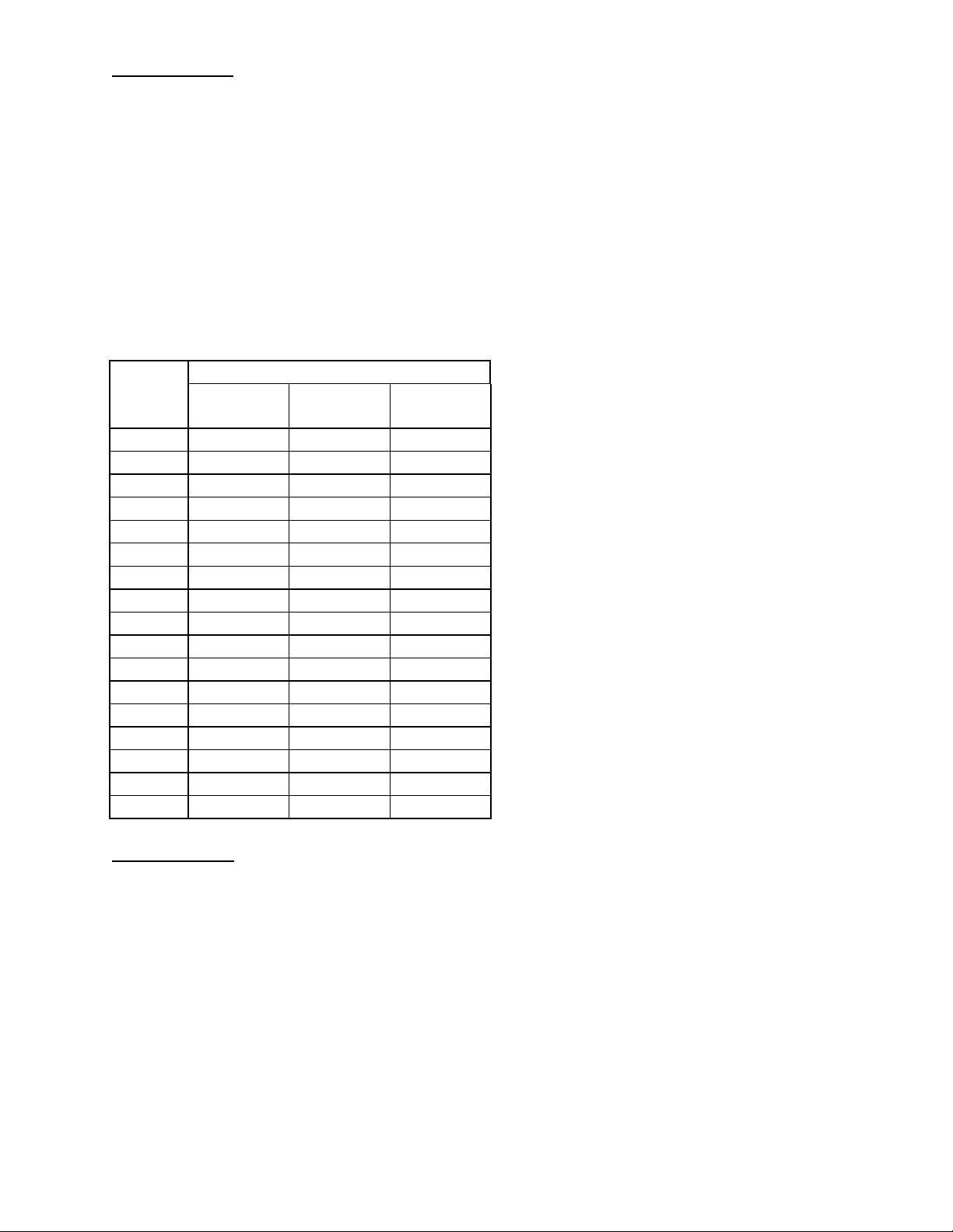
Unit Gas Piping Connection Size Chart
MBH Gas Pressure at the Unit
Input 7-8" NG
5-6” LP
100 ½" ½" ½"
200 ½" ½" ½" Note: Unless otherwise specified
300 ¾" ¾" ½" at the time of the order, the gas
400 ¾" ¾" ¾" piping will be sized according to
500 1" ¾" ¾" the 7-8" gas pressure column.
600 1" 1" ¾"
700 1-¼" 1" 1"
800 1-¼" 1" 1"
900 1-¼" 1-¼" 1"
1,000 1-¼" 1-¼" 1"
1,100 1-¼" 1-¼" 1-¼"
1,200 1-½" 1-¼" 1-¼"
1,300 1-½" 1-¼" 1-¼"
1,400 1-½" 1-¼" 1-¼"
1,500 1-½" 1-¼" 1-¼"
1,600 1-½" 1-½" 1-¼"
1,650 1-½" 1-½" 1-¼"
9-10" NG
7-8” LP
11-14" NG
9-14” LP
Wiring the Unit
Applicable codes and standards must be followed in wiring the unit. For main power
wiring, bring the wires into the factory supplied disconnect switch. If one has not been
factory provided, then a disconnect switch of sufficient ampacity must be installed
according to Article 430 of the National Electrical Code, ANSI/NFPA 70-1987. In this
case once it is installed and wired the wires should be run to the service switch inside
the control compartment. Connect any field wired control components according to the
electrical drawing furnished with the unit. Spark testing or shorting of the control wires
by any means will render the transformers inoperative. Do not allow this to happen, as
it is not covered under warranty.
The unit wiring diagram and parts list are in a plastic sheet protector inside of the control
compartment.
2
Page 4

OPTIONAL EQUIPMENT
LOW TEMPERATURE LIMIT SWITCH
This control is commonly called a Freeze Stat. This unit mounted, low limit thermostat will shut the
blower off if the discharge temperature drops below 40°F. A Bypass Timer which is part of the control will
allow the unit to run on a cold start-up. After 5 minutes, control power will pass through the low
temperature thermostat. If the remote panel has operating lights, the red light will glow on "ALARM".
Turn the unit
FLAME FAILURE RELAY
A relay is interlocked with the burner control module. When the burner fails to light within the allowable
time (30 seconds), the relay is energized, which opens the circuit to the blower starter, and shuts the unit
down. If the remote panel has operating lights, the red light will glow on "ALARM". Turn the unit
then back ON and then reset the burner control module.
MILD WEATHER THERMOSTAT
This control is often called an "Intake Air Thermostat". The sensing element of the thermostat is mounted
in the incoming air supply to the unit. If the temperature exceeds the setting of the thermostat, the burner
will de-energize. The burner will re-ignite when the outside air temperature falls below the thermostat set
point.
REMOTE CONTROL PANEL
This consists of either a three position “SUMMER-OFF-WINTER” switch in a flush mounting stainless
steel bezel plate and masonry box or two toggle switches (“FAN ON/OFF” and “HEATER ON/OFF”) in a
flush mounting stainless steel bezel plate on the kitchen hood face.
, and back ON, to reset the Bypass Timer.
OFF
OFF
,
REMOTE CONTROL PANEL WITH INDICATOR LIGHTS
Up to four labeled pilot lights are mounted on the face of the remote control panel, indicating primary
functions of the unit. The “SUMMER-OFF-WINTER” switch is included next to the pilot lights.
1 - Green - Blower Run Light – “BLOWER”
1 - Green - Burner On Light – “BURNER”
1 - Red - Low Temperature Failure Light – “ALARM”
1 - Red - Flame Failure Shut Down Light – “ALARM”
1 - Red - Clogged Filter Light – “FILTERS”
A minimum of two lights is available. If more than the standard 4-light panel is required, a circuit analyzer
panel must be used.
CLOGGED FILTER SWITCH WITH INDICATOR LIGHT
A pressure sensitive switch, mounted in the unit, will sense the air pressure drop across the filter. When
the filter becomes dirty, the switch will activate a light on the remote control panel, indicating a filter
change is required.
PREPURGE TIMER
A timer allows the unit blower to run for 1 minute, purging any gas residue in the unit, before the burner
circuit is allowed to energize.
TIME CLOCK
A time clock cycles the unit ON and
selected days, as needed.
, at selected times of the day. This time clock can also "skip"
OFF
115V DUPLEX SERVICE RECEPTACLE
The receptacle is mounted to the outside of the unit in a weatherproof enclosure. It provides power for
service equipment when the main power to the unit is shut off for service work. It requires a separate
115V circuit.
3
Page 5

CONTROL SYSTEM DIAGNOSTIC INDICATOR
This component is used as a diagnostic tool for troubleshooting burner problems. It attaches to the
burner control module monitoring the function of the module and storing in memory any failures that
occur.
AUDIBLE ALARM
An alarm horn is supplied with the remote control panel. On a flame failure, the horn will sound. A reset
of the flame failure relay will silence the horn.
DISCHARGE DAMPER WITH 2-POSITION MOTOR AND INTERLOCK
A motor operated Parallel Blade Damper can be added to the discharge of the unit. This will prevent the
warm air from escaping out of the building through the unit. The damper motor spring returns the damper
to a
CLOSED
outdoors.)
INTAKE DAMPER WITH 2-POSITION MOTOR AND INTERLOCK
A motor operated Parallel Blade Damper is installed to the fresh air intake of the unit. This keeps cold air
from entering the unit when
FILTER SECTION
The filter section with 1” cleanable or throwaway filters is supplied as standard on the units. 2" cleanable
or throwaway filters as well as Farr 30/30 throwaway filters are also available.
position during shutdown. (A discharge damper is recommended on units installed
SHUT-OFF
. (An intake damper is recommended on units installed indoors.)
INTAKE HOOD WITH BIRD SCREEN
This standard accessory is sized to fit the fresh air intake of the unit. It has 1/2" mesh birdscreen on the
face of the hood and is designed to help prevent rain or snow from entering the unit. It is shipped as a
loose item for field installation. It can be deleted on indoor units that are ducted to the outside.
GALVANIZED STEEL CURB
The standard roof curb is flat, 12" high, insulated and formed of 18 gauge galvanized steel. It fits under
the fan discharge of the unit. Other heights and one way or two-way pitches are available.
SUPPORT RAIL
It supports the rear of the unit and is sized to match the roof curb. Support legs may be necessary if an
intake hood is included.
FULL PERIMETER ROOF CURB
This curb goes under the full length of the main unit (burner and blower section). A support rail is not
required for the back of the unit. However, support legs may be necessary if an intake hood is included.
MODULAR CURB CAP AND CURB
The curb cap is custom sized to house an exhaust fan as well as the supply fan on one common curb.
The exhaust fan extension is also sized to meet NFPA96 requirements for discharge height. The supply
fan extension fits under the fan discharge like the standard curb described above.
HOUSING INSULATION
1" 1-1/2# density insulation is standard on the units. It is glued and pin spotted, to the inner surface of the
walls and ceiling of the unit. As an optional cost saving, it can be deleted from the burner and filter
sections if a discharge damper is included.
VIBRATION ISOLATORS
Isolators are standard equipment underneath the blower and motor. Floor rubber in shear, floor spring
and hanger spring isolators are also available to provide additional vibration isolation for floor mounted
and indoor hanging units. They are shipped as loose items for field installation.
4
Page 6

HIGH PRESSURE REGULATOR
It is necessary to install a high-pressure regulator upstream of the unit if the incoming gas pressure is
greater than ½ PSIG. This item ships loose for field installation and is available in 1” and 1-1/4” diameter
pipe sizes.
HIGH AND/OR LOW GAS PRESSURE SWITCH
As an option these switches are available to monitor high, low or high & low gas pressure to the burner.
If improper gas pressure is measured than the burner circuit is de-energized.
COIL COMPARTMENT (WITH OR WITHOUT COIL)
An insulated coil section for a chilled water coil can be factory installed. Housing includes access door,
drain pan and selected coil (if required). The coil compartment is custom-designed to fit the coil selected
and the unit housing size.
EVAPORATIVE COOLING SECTION
This section includes the housing, evaporative cooling media, submersible pump, float valve, overflow
coupling, drain pipe, flush valve and flow meter.
DISCHARGE LOUVERS
A field installed louver, with vertical and horizontal blades, which is designed to discharge air in four
directions. The blades are installed 2" apart, and can be manually adjusted to set direction of air flow.
CONTROLS DESCRIPTION & TESTING
1. LOW TEMPERATURE LIMIT SWITCH
This is a freeze protector. If the unit supply temperature is below the setting of this controller, it
will open the circuit (R-W) shutting the unit operation down and close the circuit (R-B) lighting the
optional “ALARM” light of the remote control panel. It also has a bypass timer that allows the unit
to run on a cold start without shutting it down.
Temperature Adjustment
Set: 40°. Bulb location in supply air duct of unit.
Test: Adjust setting above discharge temperature. The unit will shut down. (
testing run blower only.)
Timer Adjustment
Set: 5 minutes.
Test: Set timer at "0" minutes. The control circuit will be through low temp limit. Turn low temp limit up
and the unit will shut down. Set timer at 5 minutes; reset timer and adjust low temp limit to 40
setting and the unit will continue to operate through the time contacts. To reset timer turn power
"OFF" and back "ON".
NOTE:
For ease of
°
5
Page 7

2. DAMPER MOTOR
The function of the damper motor is to power open or spring return close the dampers on the
discharge or intake of the unit. It will seal off or open the building to the make-up air supply.
Test: Remove damper motor linkage cover. Energize unit. Damper motor will open, pushing linkage to
open the damper blades. De-energize unit. Damper motor will close damper blades by spring
return.
3. AIR FLOW SWITCH
The function of this switch is to prove proper air flow across the burner before the burner circuit
can be energized.
Set: 0.3" W.C. for DFG-10/12 units.
0.4” W.C. for DFG-15/18/20 units.
Test: Restrict inlet or discharge to unit 50%. Air flow switch should open circuit to burner.
4. HIGH TEMPERATURE LIMIT SWITCH
The function of this control is a manual reset thermal cutout for primary over-temperature
protection of the unit.
Set: 155°F for DFG-10/12 units.
190°F for DFG-15/18/20 units.
Test: Adjust unit to high fire. Place thermometer in unit discharge. Close intake down until unit has
excessive cabinet temperature. This limit should trip at 200°F.
5. MILD WEATHER THERMOSTAT
The function of this control is to sense inlet temperature and act as an economizer. It will take
the burner out of the circuit if the inlet temperature is above the control setting.
Set: 5°F below room or discharge temperature controller.
Test: Adjust control setting below inlet temperature. Burner circuit will de-energize. Adjust above inlet
temperature. Burner circuit will energize.
6. HIGH GAS PRESSURE SWITCH
The function of this switch is to de-energize the burner circuit if the gas pressure to the burner is
above its setting.
Set: 8" W.C. - Manual reset to energize.
Test: Using test gauge in parallel with sensing tubing, adjust unit to high fire, increase regulator
pressure at gauge above 8" W.C.
6
Page 8

7. LOW GAS PRESSURE SWITCH
The function of this switch is to de-energize the burner circuit if the gas pressure to the burner is
below its setting. Manual reset to energize.
Set: 2" W.C.
Test: Using test gauge in parallel with sensing tubing, adjust unit to high fire, decrease regulator
pressure at gauge below 2" W.C.
8. BURNER CONTROL MODULE
This module supervises the flame circuit and the energizing of the ignition/pilot and main gas
valves. A milli-volt circuit is used for flame detection and response.
Set: 1.25-5.0 Vdc signal on pilot flame.
Test: Fire unit, with manual shut-off valve decrease gas flow to burner until micro amp reading drops
and the relay causes the main gas valves to close. The safety circuit will cut out in 30 seconds.
9. ROOM OVERRIDE THERMOSTAT
The function of this thermostat is to cycle the unit to high fire if the room temperature requirement
is not being met. It overrides the ductstat on Maxitrol series 14 systems. It ships loose and
should be mounted in a location that has a representative temperature for the room.
Set: Desired room temperature.
10. ELECTRONIC MODULATING VALVE
The function of this control is to proportion the amount of gas to the burner to maintain the
desired discharge supply air temperature. This control uses an electric coil with a floating plunge
that will vary the force on a gas supply orifice supplying gas to the main burner. A 24V D.C.
signal positions the plunger inside the electric coil. At 0-5 volts it will be low fire; at 5-15 volts
modulation; and 15-24 volts at high fire.
Test: Check plunger for up and down motion by varying the voltage to the valve.
11. AMPLIFIER
This control converts 24 volts A.C. to 24 volt D.C. and varies the voltage to the modulating valve.
Test: Check input at transformer terminal for 24 volt A.C. -- check output at modulator terminals for 24
volt D.C. output while adjusting the temperature set point.
12. DISCHARGE AIR TEMPERATURE SENSOR
Discharge Control Units (Series 14):
The function of this sensor is to monitor discharge supply air temperature and with a temperature
sensitive element send a signal to the amplifier to make any necessary temperature adjustments.
Room Control Units (Series 44):
The function of this sensor is to monitor the discharge supply air temperature and with
temperature sensitive elements send a signal to the amplifier to maintain the maximum and
minimum discharge temperatures of the unit. It works together with the Room Selectrastat.
7
Page 9

13. REMOTE TEMPERATURE SELECTOR
The function of this dial is to set the desired discharge temperature the unit is to supply. This dial
working in conjunction with the discharge temperature sensor sends a D.C. voltage signal to the
amplifier that modulates the burner to a specific supply temperature.
14. ROOM SELECTRASTAT
The function of this room thermostat is to vary a D.C. voltage signal to the amplifier that will
modulate the burner to maintain a supply air temperature to satisfy space temperature.
15. CLOGGED FILTER SWITCH & LIGHT
The function of this control system is to sense by negative pressure a dirty filter condition and
signal that filter maintenance is required. With a negative pressure above the setting of the filter
switch (sensed on the leaving side of the filter), the switch will trip, energizing the filter light on the
remote control panel.
Set: A visual inspection should be made of the filters until the first cleaning is necessary. At this time
adjustment of the switch should be made. Turn switch adjustment clockwise until the switch
closes. After cleaning or replacing the filters, check to make sure the light is no longer lit.
16. TIME CLOCK
The function of this clock is to cycle the unit "ON" or "OFF" for a set time period during each 24
hour period on a constant running unit; or to cycle the unit from day to night for day/night
operating units. On day/night units, the remote control panel will have a time clock override
switch that can be used on the time "OFF" periods to switch the unit back on to constant running.
Set: Program the unit for the desired time "ON" and "OFF". Instructions are included with the time
clock.
17. PREPURGE TIMER
The function of this timer is to purge the combustion area and the discharge supply duct before
the burner flame safety circuit is energized.
Burner circuit power will energize the pre-purge timer. When the timed purging period is over,
the flame safety circuit will be energized.
Set: 1 minute.
18. AUDIBLE ALARM
The function of this alarm is to give an audible alarm signal down in the space, along with the
alarm light on the remote panel, when there is a burner flame failure.
On a flame failure, and after a 30 second safety timing period, the alarm contacts of the burner
control module will close. This will energize the flame failure light and the audible alarm. To
silence the alarm, the green reset button on the flame safety will need to be reset.
8
Page 10

TROUBLE SHOOTING GUIDE
If a service problem should occur, the following guide can be used to isolate and correct
the problem.
IMPORTANT:
Before this heater will operate, the following conditions must be met and, therefore,
should be checked before proceeding to the steps of the "Trouble Shooting" section
herein.
1. Adequate supply of air into intake of the unit -- check for obstructions in intake
hood and filters.
2. Proper fuel pressure -- all supply valves open and proper gas pressure supplied
as stated on unit identification plate.
3. All circuit breakers and disconnects turned on and adequate electrical power to
unit.
A. BLOWER MOTOR FAILS TO START. REMEDY
Probable
Cause:
1. Fuse blown in unit disconnect. Replace fuse.
2. Motor starter out on overload. Press red reset button overload.
3. Remote switch in OFF position. Turn to summer or winter position.
4. Unit shut down on flame safety. Press reset button on flame
safety relay.
5. Unit shut down on low Re-energize power to low
temperature safety. Temperature limit by turning
power “OFF” and then “ON”.
6. Defective motor. Replace motor.
7. No power to motor starter Check preceding controls
coil. for open circuit.
9
Page 11

B. BLOWER MOTOR STARTER
GOES OUT ON OVERLOAD. REMEDY
Probable
Cause:
____________________________________________________________________
C. PILOT WILL NOT LIGHT REMEDY
Probable
Cause:
1. Motor drawing too many amps. Slow blower RPM down.
2. Loose wiring. Check wire connections.
3. Low voltage to unit. Check power supply to unit.
4. Defective motor. Replace motor.
5. Belts too tight. Adjust belts for 1" deflection.
6. Defective blower bearings. Replace bearings.
7. Dirty blower wheel. Clean blower.
8. Defective starter overload. Replace starter overload.
1. No power to burner control Check preceding controls for
module. open circuit.
2. Air in pilot line. Purge air from pilot line.
3. Low gas pressure. Supply unit with pressure stated
on unit identification plate.
4. Burner control module locked Press reset button on
out. burner control module.
5. Pilot regulator out of Adjust unit pilot regulator to
adjustment. increase pilot gas supply.
6. Pilot regulator locked up. Gas pressure to unit is excessive;
decrease supply pressure.
7. Defective ignition transformer. Replace transformer.
8. Incorrect spark gap. Adjust gap.
9. Defective pilot solenoid valve. Replace valve.
10. Defective burner control Replace module.
module.
10
Page 12

D. PILOT LIGHTS, BUT FLAME SAFETY
LOCKS OUT AFTER 30 SECONDS REMEDY
Probable
Cause:
1. Defective flame rod. Check porcelain for cracks.
Replace rod if crack is visible.
2. Pilot flame too small. Adjust pilot gas regulator to
increase pilot flame.
3. Defective burner control If micro-amp meter measures
module. 3 milliamps or more to module
and it locks out, replace relay.
____________________________________________________________________
E. PILOT LIGHTS AND FLAME SAFETY
PROVES PILOT, BUT NO MAIN FLAME REMEDY
Probable
1. Main gas valve shut-off. Open main valve.
Cause:
2. Defective main gas valve. Replace valve.
3. Low gas pressure. Adjust gas pressure as stated
on unit identification plate.
4. Loose wiring. Check wire connections.
5. Deflective burner control Replace module.
module.
____________________________________________________________________
F. UNIT OVER-FIRE (Excessive
Temperature Rise) REMEDY
Probable
Cause:
1. Excessive gas pressure. Adjust gas pressure as stated on
unit identification plate.
2. Loose belts. Adjust belts for 1" deflection.
3. Dirty filters. Remove filters and clean.
4. Excessive external static Adjust motor sheave to increase
pressure. blower RPM (beware of over-
loading motor) or adjust temp.
rise using regulator inside unit.
5. Dirty blower wheel. Clean blower wheel.
6. Foreign matter on intake Remove obstruction.
screen.
11
Page 13

G. UNIT UNDER-FIRED (Temperature
Rise Too Low) REMEDY
Probable
Cause:
____________________________________________________________________
H. BURNER WON'T MODULATE --
ELECTRONIC CONTROL SYSTEMS
1. Lack of gas pressure. Adjust gas pressure as stated on
unit identification plate.
2. Lack of static external Adjust motor sheave to
pressure. decrease blower RPM or adjust
temperature rise using regulator
inside unit.
3. Gas line obstruction. Remove obstruction.
4. Dirty burner. Clean burner.
5. Defective gas valve. Replace valve.
6. Improper adjustment of Adjust temperature rise per
temperature rise. start-up card or instruction in
manual.
1. Refer to Maxitrol Series 14 Installation, Instruction and Field
Service Check List included in the next pages of this manual.
12
Page 14

START-UP OF THE UNIT
1. Turn the remote switch to the "OFF" position.
2. Turn the main disconnect switch to the "OFF" position.
3. Remove the control cabinet cover and the blower cabinet cover.
4. Turn all the manual gas shutoff valves to the "OFF" position.
5. Check to make sure that all wiring has been completed according to the furnished wiring
diagram including the installation of all field installed components.
6. Check all wiring terminals for tightness and good connection.
7. Make sure all manual resets have been reset.
8. Check all gas line connections for leaks including those within the unit.
9. Measure the incoming gas supply pressure at the field installed 1/8" tap upstream of the
unit. Verify that it falls within the minimum and maximum nameplate values.
10. Check that pulleys are in alignment and locked to the shaft.
11. Check for the proper input voltage (given on the nameplate).
12. Turn the remote fan switch to the "ON" or "SUMMER" position (depending on which
remote control option was ordered) and turn the main disconnect to the "ON" position.
13. Verify fan rotation, belt tension and motor amp draw. Make certain the blower motor is not
overloaded. Replace the blower cabinet cover.
14. Set the remote temperature selector above the outside air temperature to simulate a call
for heat.
15. Open pilot gas shutoff valve.
16. Turn the remote heater switch to the "ON" or "WINTER" position (depending on which
remote control option was ordered).
17. Verify that the burner control module energizes the ignition transformer, opens the pilot
valve, that the pilot flame is established and that the main valves are then energized.
18. Using a volt-ohmmeter, measure the flame signal at the +/- test jacks on the flame signal
amplifier (refer to the Honeywell RM7890 manual for more detailed instructions). The
signal should measure between 1.25 and 5.0 Vdc. Adjust the pilot pressure regulator to
obtain a value near the midpoint of the range.
19. If the outside air temperature is high, the high temperature limit may have to be jumpered
to prevent shutdown during the following high fire adjustment. Reset it to a value greater
than 120 degrees above the outside air temperature.
13
Page 15

20. Open the main gas shutoff valve. Disconnect the wire from the "A4" terminal block. This
will cause the unit to call for continuous high fire.
21. Check the outside air temperature and add the nameplate temperature rise to this value.
Measure the discharge air temperature. Adjust the main gas pressure at the main
pressure regulator until the proper discharge temperature determined above is reached.
On units with the Maxitrol MR212 valve, there is no separate regulator. Adjust the main
gas pressure at this valve (refer to the Maxitrol installation instructions).
22. Observe the main burner flame for proper flame length. The flame should be 13-16" in
length, as measured from the end of the burner to the end of the stable part of the flame
(exclude any wisps of flashes). If the flame is too long, if it contains excess yellow flame,
or if it tends to rise, low air velocity is indicated. If the flame is very short and all blue,
excess velocity is apparent. Shut down the heater and adjust the profile plates as
required.
23. If profile plates have been adjusted, then recheck the temperature rise as in step # 23.
Adjust the regulator if necessary.
24. Reconnect the wire to the "A4" terminal block. Disconnect the wire to the "A8" terminal
block. This will cause the unit to call for continuous low fire.
25. Reduce the low fire stop on the modulating valve until the flame tends to go out. Then
increase it to the smallest stable, full length fire. If a local weak spot appears, check for
clogged low fire air ports. Make low fire adjustments patiently. Due to the low gas flow
rate, response to adjustments will be slow. Refer to the Maxitrol installation instructions on
how to make these adjustments.
26. Reconnect the wire to the "A8" terminal block. Remove the jumper on the high
temperature limit. Reset the remote temperature selector to the desired discharge air
temperature.
27. Check unit for proper function of the control operations (refer to the Controls Description
and Testing section).
14
Page 16

MAINTENANCE SCHEDULE
Service and maintenance should be performed four times a year (three-month intervals)
or after every 2,000 hours of operation. The following items should be checked at each
inspection:
A) Check wear and tension of the belt; replace if necessary. (Tension of the new
belt should be re-adjusted after first two weeks of operation to compensate for
stretching.)
B) Check cleanliness of the burner. Clean air ports are essential for good burner
operation. Check the burner every two weeks, if required, because of dirty
atmosphere.
C) Check filters, if supplied, for cleanliness. Clean and replace, if necessary.
D) Check and clean blower wheel at least once a year. Inspection can be made by
removing the blower access panel. Clean as necessary.
E) Check ceramic insulators on flame rod and spark rod for cracks and
deterioration. Replace if necessary.
F) Check the motor. Clean air inlets of motor, if needed.
G) Check and clean end fittings of discharge air sensor.
H) Check damper linkage and operation. Oil linkage as needed.
I) Grease bearing on unit with pillow block bearings.
15
DFGI&M 12/04
 Loading...